EP2955245A1 - Procédé de fabrication d'un film transparent faisant barrière aux gaz, dispositif de fabrication d'un film transparent faisant barrière aux gaz, et dispositif électroluminescent organique - Google Patents
Procédé de fabrication d'un film transparent faisant barrière aux gaz, dispositif de fabrication d'un film transparent faisant barrière aux gaz, et dispositif électroluminescent organique Download PDFInfo
- Publication number
- EP2955245A1 EP2955245A1 EP14749069.2A EP14749069A EP2955245A1 EP 2955245 A1 EP2955245 A1 EP 2955245A1 EP 14749069 A EP14749069 A EP 14749069A EP 2955245 A1 EP2955245 A1 EP 2955245A1
- Authority
- EP
- European Patent Office
- Prior art keywords
- resin substrate
- gas barrier
- transparent gas
- deposition area
- density
- Prior art date
- Legal status (The legal status is an assumption and is not a legal conclusion. Google has not performed a legal analysis and makes no representation as to the accuracy of the status listed.)
- Withdrawn
Links
- 238000004519 manufacturing process Methods 0.000 title claims abstract description 79
- 238000005401 electroluminescence Methods 0.000 title claims description 8
- 239000000758 substrate Substances 0.000 claims abstract description 209
- 229920005989 resin Polymers 0.000 claims abstract description 184
- 239000011347 resin Substances 0.000 claims abstract description 184
- 238000000151 deposition Methods 0.000 claims abstract description 137
- 230000004888 barrier function Effects 0.000 claims abstract description 133
- 230000008021 deposition Effects 0.000 claims abstract description 130
- 239000000463 material Substances 0.000 claims abstract description 42
- 229910052751 metal Inorganic materials 0.000 claims abstract description 22
- 239000002184 metal Substances 0.000 claims abstract description 22
- 150000002739 metals Chemical class 0.000 claims abstract description 15
- 238000000034 method Methods 0.000 claims abstract description 14
- 238000005096 rolling process Methods 0.000 claims abstract description 7
- 239000010410 layer Substances 0.000 claims description 206
- 239000007789 gas Substances 0.000 claims description 152
- 150000004767 nitrides Chemical class 0.000 claims description 29
- 239000012495 reaction gas Substances 0.000 claims description 25
- 230000008859 change Effects 0.000 claims description 17
- 238000007789 sealing Methods 0.000 claims description 15
- 230000007423 decrease Effects 0.000 claims description 11
- 239000012044 organic layer Substances 0.000 claims description 7
- 239000010408 film Substances 0.000 description 66
- 208000028659 discharge Diseases 0.000 description 16
- 239000010409 thin film Substances 0.000 description 11
- MWUXSHHQAYIFBG-UHFFFAOYSA-N Nitric oxide Chemical compound O=[N] MWUXSHHQAYIFBG-UHFFFAOYSA-N 0.000 description 8
- 238000009826 distribution Methods 0.000 description 7
- 238000010891 electric arc Methods 0.000 description 6
- 238000005192 partition Methods 0.000 description 6
- 238000011144 upstream manufacturing Methods 0.000 description 6
- IJGRMHOSHXDMSA-UHFFFAOYSA-N Atomic nitrogen Chemical compound N#N IJGRMHOSHXDMSA-UHFFFAOYSA-N 0.000 description 5
- QVGXLLKOCUKJST-UHFFFAOYSA-N atomic oxygen Chemical compound [O] QVGXLLKOCUKJST-UHFFFAOYSA-N 0.000 description 5
- 230000015572 biosynthetic process Effects 0.000 description 5
- 239000001301 oxygen Substances 0.000 description 5
- 229910052760 oxygen Inorganic materials 0.000 description 5
- GQPLMRYTRLFLPF-UHFFFAOYSA-N Nitrous Oxide Chemical compound [O-][N+]#N GQPLMRYTRLFLPF-UHFFFAOYSA-N 0.000 description 4
- FYYHWMGAXLPEAU-UHFFFAOYSA-N Magnesium Chemical compound [Mg] FYYHWMGAXLPEAU-UHFFFAOYSA-N 0.000 description 3
- ATUOYWHBWRKTHZ-UHFFFAOYSA-N Propane Chemical compound CCC ATUOYWHBWRKTHZ-UHFFFAOYSA-N 0.000 description 3
- XUIMIQQOPSSXEZ-UHFFFAOYSA-N Silicon Chemical compound [Si] XUIMIQQOPSSXEZ-UHFFFAOYSA-N 0.000 description 3
- 229910052782 aluminium Inorganic materials 0.000 description 3
- XAGFODPZIPBFFR-UHFFFAOYSA-N aluminium Chemical compound [Al] XAGFODPZIPBFFR-UHFFFAOYSA-N 0.000 description 3
- 239000013078 crystal Substances 0.000 description 3
- 230000003247 decreasing effect Effects 0.000 description 3
- 239000011521 glass Substances 0.000 description 3
- 229910052749 magnesium Inorganic materials 0.000 description 3
- 239000011777 magnesium Substances 0.000 description 3
- VNWKTOKETHGBQD-UHFFFAOYSA-N methane Chemical compound C VNWKTOKETHGBQD-UHFFFAOYSA-N 0.000 description 3
- -1 polyethylene naphthalate Polymers 0.000 description 3
- 229920000642 polymer Polymers 0.000 description 3
- 230000008569 process Effects 0.000 description 3
- 229910052710 silicon Inorganic materials 0.000 description 3
- 239000010703 silicon Substances 0.000 description 3
- XLYOFNOQVPJJNP-UHFFFAOYSA-N water Chemical compound O XLYOFNOQVPJJNP-UHFFFAOYSA-N 0.000 description 3
- XKRFYHLGVUSROY-UHFFFAOYSA-N Argon Chemical compound [Ar] XKRFYHLGVUSROY-UHFFFAOYSA-N 0.000 description 2
- OKTJSMMVPCPJKN-UHFFFAOYSA-N Carbon Chemical compound [C] OKTJSMMVPCPJKN-UHFFFAOYSA-N 0.000 description 2
- 239000004215 Carbon black (E152) Substances 0.000 description 2
- HBBGRARXTFLTSG-UHFFFAOYSA-N Lithium ion Chemical compound [Li+] HBBGRARXTFLTSG-UHFFFAOYSA-N 0.000 description 2
- UCKMPCXJQFINFW-UHFFFAOYSA-N Sulphide Chemical compound [S-2] UCKMPCXJQFINFW-UHFFFAOYSA-N 0.000 description 2
- 229910052799 carbon Inorganic materials 0.000 description 2
- 239000011248 coating agent Substances 0.000 description 2
- 238000000576 coating method Methods 0.000 description 2
- 230000006866 deterioration Effects 0.000 description 2
- 238000010894 electron beam technology Methods 0.000 description 2
- 238000001704 evaporation Methods 0.000 description 2
- 238000010438 heat treatment Methods 0.000 description 2
- 229930195733 hydrocarbon Natural products 0.000 description 2
- 150000002430 hydrocarbons Chemical class 0.000 description 2
- 238000002347 injection Methods 0.000 description 2
- 239000007924 injection Substances 0.000 description 2
- 238000009434 installation Methods 0.000 description 2
- 238000010030 laminating Methods 0.000 description 2
- 229910001416 lithium ion Inorganic materials 0.000 description 2
- 239000000203 mixture Substances 0.000 description 2
- 229910052757 nitrogen Inorganic materials 0.000 description 2
- QJGQUHMNIGDVPM-UHFFFAOYSA-N nitrogen group Chemical group [N] QJGQUHMNIGDVPM-UHFFFAOYSA-N 0.000 description 2
- 238000004806 packaging method and process Methods 0.000 description 2
- 230000035699 permeability Effects 0.000 description 2
- 230000001737 promoting effect Effects 0.000 description 2
- 229920002545 silicone oil Polymers 0.000 description 2
- 239000007784 solid electrolyte Substances 0.000 description 2
- 238000003860 storage Methods 0.000 description 2
- 229920000089 Cyclic olefin copolymer Polymers 0.000 description 1
- OTMSDBZUPAUEDD-UHFFFAOYSA-N Ethane Chemical compound CC OTMSDBZUPAUEDD-UHFFFAOYSA-N 0.000 description 1
- VGGSQFUCUMXWEO-UHFFFAOYSA-N Ethene Chemical compound C=C VGGSQFUCUMXWEO-UHFFFAOYSA-N 0.000 description 1
- 239000005977 Ethylene Substances 0.000 description 1
- 239000004952 Polyamide Substances 0.000 description 1
- 239000004698 Polyethylene Substances 0.000 description 1
- 239000004642 Polyimide Substances 0.000 description 1
- 229910052581 Si3N4 Inorganic materials 0.000 description 1
- VYPSYNLAJGMNEJ-UHFFFAOYSA-N Silicium dioxide Chemical compound O=[Si]=O VYPSYNLAJGMNEJ-UHFFFAOYSA-N 0.000 description 1
- RTAQQCXQSZGOHL-UHFFFAOYSA-N Titanium Chemical compound [Ti] RTAQQCXQSZGOHL-UHFFFAOYSA-N 0.000 description 1
- 239000000853 adhesive Substances 0.000 description 1
- 230000001070 adhesive effect Effects 0.000 description 1
- 239000012790 adhesive layer Substances 0.000 description 1
- 229910052786 argon Inorganic materials 0.000 description 1
- 238000005452 bending Methods 0.000 description 1
- 230000005540 biological transmission Effects 0.000 description 1
- 229910052797 bismuth Inorganic materials 0.000 description 1
- JCXGWMGPZLAOME-UHFFFAOYSA-N bismuth atom Chemical compound [Bi] JCXGWMGPZLAOME-UHFFFAOYSA-N 0.000 description 1
- 239000001273 butane Substances 0.000 description 1
- 150000001875 compounds Chemical class 0.000 description 1
- 239000000470 constituent Substances 0.000 description 1
- HVMJUDPAXRRVQO-UHFFFAOYSA-N copper indium Chemical compound [Cu].[In] HVMJUDPAXRRVQO-UHFFFAOYSA-N 0.000 description 1
- 238000003851 corona treatment Methods 0.000 description 1
- 238000005520 cutting process Methods 0.000 description 1
- 230000032798 delamination Effects 0.000 description 1
- ZZEMEJKDTZOXOI-UHFFFAOYSA-N digallium;selenium(2-) Chemical compound [Ga+3].[Ga+3].[Se-2].[Se-2].[Se-2] ZZEMEJKDTZOXOI-UHFFFAOYSA-N 0.000 description 1
- 239000005038 ethylene vinyl acetate Substances 0.000 description 1
- 230000008020 evaporation Effects 0.000 description 1
- 230000006870 function Effects 0.000 description 1
- 229910052732 germanium Inorganic materials 0.000 description 1
- GNPVGFCGXDBREM-UHFFFAOYSA-N germanium atom Chemical compound [Ge] GNPVGFCGXDBREM-UHFFFAOYSA-N 0.000 description 1
- 230000009477 glass transition Effects 0.000 description 1
- 230000005525 hole transport Effects 0.000 description 1
- 238000009396 hybridization Methods 0.000 description 1
- 230000006872 improvement Effects 0.000 description 1
- 229910052738 indium Inorganic materials 0.000 description 1
- APFVFJFRJDLVQX-UHFFFAOYSA-N indium atom Chemical compound [In] APFVFJFRJDLVQX-UHFFFAOYSA-N 0.000 description 1
- AMGQUBHHOARCQH-UHFFFAOYSA-N indium;oxotin Chemical compound [In].[Sn]=O AMGQUBHHOARCQH-UHFFFAOYSA-N 0.000 description 1
- 239000011261 inert gas Substances 0.000 description 1
- 229910010272 inorganic material Inorganic materials 0.000 description 1
- 239000011147 inorganic material Substances 0.000 description 1
- 239000004973 liquid crystal related substance Substances 0.000 description 1
- 230000007246 mechanism Effects 0.000 description 1
- 230000004048 modification Effects 0.000 description 1
- 238000012986 modification Methods 0.000 description 1
- IJDNQMDRQITEOD-UHFFFAOYSA-N n-butane Chemical compound CCCC IJDNQMDRQITEOD-UHFFFAOYSA-N 0.000 description 1
- OFBQJSOFQDEBGM-UHFFFAOYSA-N n-pentane Natural products CCCCC OFBQJSOFQDEBGM-UHFFFAOYSA-N 0.000 description 1
- 229960001730 nitrous oxide Drugs 0.000 description 1
- 235000013842 nitrous oxide Nutrition 0.000 description 1
- 229920003207 poly(ethylene-2,6-naphthalate) Polymers 0.000 description 1
- 229920001200 poly(ethylene-vinyl acetate) Polymers 0.000 description 1
- 229920002647 polyamide Polymers 0.000 description 1
- 229920000515 polycarbonate Polymers 0.000 description 1
- 239000004417 polycarbonate Substances 0.000 description 1
- 229920000573 polyethylene Polymers 0.000 description 1
- 239000011112 polyethylene naphthalate Substances 0.000 description 1
- 229920001721 polyimide Polymers 0.000 description 1
- 229920006389 polyphenyl polymer Polymers 0.000 description 1
- 239000001294 propane Substances 0.000 description 1
- 230000009257 reactivity Effects 0.000 description 1
- 230000009467 reduction Effects 0.000 description 1
- HQVNEWCFYHHQES-UHFFFAOYSA-N silicon nitride Chemical compound N12[Si]34N5[Si]62N3[Si]51N64 HQVNEWCFYHHQES-UHFFFAOYSA-N 0.000 description 1
- 229910052814 silicon oxide Inorganic materials 0.000 description 1
- 229910052709 silver Inorganic materials 0.000 description 1
- 239000004332 silver Substances 0.000 description 1
- 239000002356 single layer Substances 0.000 description 1
- 238000009751 slip forming Methods 0.000 description 1
- 238000000992 sputter etching Methods 0.000 description 1
- 239000000126 substance Substances 0.000 description 1
- 229910052719 titanium Inorganic materials 0.000 description 1
- 239000010936 titanium Substances 0.000 description 1
- 238000004804 winding Methods 0.000 description 1
- YVTHLONGBIQYBO-UHFFFAOYSA-N zinc indium(3+) oxygen(2-) Chemical compound [O--].[Zn++].[In+3] YVTHLONGBIQYBO-UHFFFAOYSA-N 0.000 description 1
Images



Classifications
-
- C—CHEMISTRY; METALLURGY
- C23—COATING METALLIC MATERIAL; COATING MATERIAL WITH METALLIC MATERIAL; CHEMICAL SURFACE TREATMENT; DIFFUSION TREATMENT OF METALLIC MATERIAL; COATING BY VACUUM EVAPORATION, BY SPUTTERING, BY ION IMPLANTATION OR BY CHEMICAL VAPOUR DEPOSITION, IN GENERAL; INHIBITING CORROSION OF METALLIC MATERIAL OR INCRUSTATION IN GENERAL
- C23C—COATING METALLIC MATERIAL; COATING MATERIAL WITH METALLIC MATERIAL; SURFACE TREATMENT OF METALLIC MATERIAL BY DIFFUSION INTO THE SURFACE, BY CHEMICAL CONVERSION OR SUBSTITUTION; COATING BY VACUUM EVAPORATION, BY SPUTTERING, BY ION IMPLANTATION OR BY CHEMICAL VAPOUR DEPOSITION, IN GENERAL
- C23C14/00—Coating by vacuum evaporation, by sputtering or by ion implantation of the coating forming material
- C23C14/22—Coating by vacuum evaporation, by sputtering or by ion implantation of the coating forming material characterised by the process of coating
- C23C14/56—Apparatus specially adapted for continuous coating; Arrangements for maintaining the vacuum, e.g. vacuum locks
- C23C14/562—Apparatus specially adapted for continuous coating; Arrangements for maintaining the vacuum, e.g. vacuum locks for coating elongated substrates
-
- C—CHEMISTRY; METALLURGY
- C23—COATING METALLIC MATERIAL; COATING MATERIAL WITH METALLIC MATERIAL; CHEMICAL SURFACE TREATMENT; DIFFUSION TREATMENT OF METALLIC MATERIAL; COATING BY VACUUM EVAPORATION, BY SPUTTERING, BY ION IMPLANTATION OR BY CHEMICAL VAPOUR DEPOSITION, IN GENERAL; INHIBITING CORROSION OF METALLIC MATERIAL OR INCRUSTATION IN GENERAL
- C23C—COATING METALLIC MATERIAL; COATING MATERIAL WITH METALLIC MATERIAL; SURFACE TREATMENT OF METALLIC MATERIAL BY DIFFUSION INTO THE SURFACE, BY CHEMICAL CONVERSION OR SUBSTITUTION; COATING BY VACUUM EVAPORATION, BY SPUTTERING, BY ION IMPLANTATION OR BY CHEMICAL VAPOUR DEPOSITION, IN GENERAL
- C23C14/00—Coating by vacuum evaporation, by sputtering or by ion implantation of the coating forming material
- C23C14/22—Coating by vacuum evaporation, by sputtering or by ion implantation of the coating forming material characterised by the process of coating
- C23C14/24—Vacuum evaporation
- C23C14/32—Vacuum evaporation by explosion; by evaporation and subsequent ionisation of the vapours, e.g. ion-plating
-
- B—PERFORMING OPERATIONS; TRANSPORTING
- B32—LAYERED PRODUCTS
- B32B—LAYERED PRODUCTS, i.e. PRODUCTS BUILT-UP OF STRATA OF FLAT OR NON-FLAT, e.g. CELLULAR OR HONEYCOMB, FORM
- B32B27/00—Layered products comprising a layer of synthetic resin
- B32B27/06—Layered products comprising a layer of synthetic resin as the main or only constituent of a layer, which is next to another layer of the same or of a different material
-
- B—PERFORMING OPERATIONS; TRANSPORTING
- B32—LAYERED PRODUCTS
- B32B—LAYERED PRODUCTS, i.e. PRODUCTS BUILT-UP OF STRATA OF FLAT OR NON-FLAT, e.g. CELLULAR OR HONEYCOMB, FORM
- B32B5/00—Layered products characterised by the non- homogeneity or physical structure, i.e. comprising a fibrous, filamentary, particulate or foam layer; Layered products characterised by having a layer differing constitutionally or physically in different parts
- B32B5/14—Layered products characterised by the non- homogeneity or physical structure, i.e. comprising a fibrous, filamentary, particulate or foam layer; Layered products characterised by having a layer differing constitutionally or physically in different parts characterised by a layer differing constitutionally or physically in different parts, e.g. denser near its faces
- B32B5/145—Variation across the thickness of the layer
-
- C—CHEMISTRY; METALLURGY
- C23—COATING METALLIC MATERIAL; COATING MATERIAL WITH METALLIC MATERIAL; CHEMICAL SURFACE TREATMENT; DIFFUSION TREATMENT OF METALLIC MATERIAL; COATING BY VACUUM EVAPORATION, BY SPUTTERING, BY ION IMPLANTATION OR BY CHEMICAL VAPOUR DEPOSITION, IN GENERAL; INHIBITING CORROSION OF METALLIC MATERIAL OR INCRUSTATION IN GENERAL
- C23C—COATING METALLIC MATERIAL; COATING MATERIAL WITH METALLIC MATERIAL; SURFACE TREATMENT OF METALLIC MATERIAL BY DIFFUSION INTO THE SURFACE, BY CHEMICAL CONVERSION OR SUBSTITUTION; COATING BY VACUUM EVAPORATION, BY SPUTTERING, BY ION IMPLANTATION OR BY CHEMICAL VAPOUR DEPOSITION, IN GENERAL
- C23C16/00—Chemical coating by decomposition of gaseous compounds, without leaving reaction products of surface material in the coating, i.e. chemical vapour deposition [CVD] processes
- C23C16/44—Chemical coating by decomposition of gaseous compounds, without leaving reaction products of surface material in the coating, i.e. chemical vapour deposition [CVD] processes characterised by the method of coating
- C23C16/455—Chemical coating by decomposition of gaseous compounds, without leaving reaction products of surface material in the coating, i.e. chemical vapour deposition [CVD] processes characterised by the method of coating characterised by the method used for introducing gases into reaction chamber or for modifying gas flows in reaction chamber
-
- C—CHEMISTRY; METALLURGY
- C23—COATING METALLIC MATERIAL; COATING MATERIAL WITH METALLIC MATERIAL; CHEMICAL SURFACE TREATMENT; DIFFUSION TREATMENT OF METALLIC MATERIAL; COATING BY VACUUM EVAPORATION, BY SPUTTERING, BY ION IMPLANTATION OR BY CHEMICAL VAPOUR DEPOSITION, IN GENERAL; INHIBITING CORROSION OF METALLIC MATERIAL OR INCRUSTATION IN GENERAL
- C23C—COATING METALLIC MATERIAL; COATING MATERIAL WITH METALLIC MATERIAL; SURFACE TREATMENT OF METALLIC MATERIAL BY DIFFUSION INTO THE SURFACE, BY CHEMICAL CONVERSION OR SUBSTITUTION; COATING BY VACUUM EVAPORATION, BY SPUTTERING, BY ION IMPLANTATION OR BY CHEMICAL VAPOUR DEPOSITION, IN GENERAL
- C23C16/00—Chemical coating by decomposition of gaseous compounds, without leaving reaction products of surface material in the coating, i.e. chemical vapour deposition [CVD] processes
- C23C16/44—Chemical coating by decomposition of gaseous compounds, without leaving reaction products of surface material in the coating, i.e. chemical vapour deposition [CVD] processes characterised by the method of coating
- C23C16/458—Chemical coating by decomposition of gaseous compounds, without leaving reaction products of surface material in the coating, i.e. chemical vapour deposition [CVD] processes characterised by the method of coating characterised by the method used for supporting substrates in the reaction chamber
-
- C—CHEMISTRY; METALLURGY
- C23—COATING METALLIC MATERIAL; COATING MATERIAL WITH METALLIC MATERIAL; CHEMICAL SURFACE TREATMENT; DIFFUSION TREATMENT OF METALLIC MATERIAL; COATING BY VACUUM EVAPORATION, BY SPUTTERING, BY ION IMPLANTATION OR BY CHEMICAL VAPOUR DEPOSITION, IN GENERAL; INHIBITING CORROSION OF METALLIC MATERIAL OR INCRUSTATION IN GENERAL
- C23C—COATING METALLIC MATERIAL; COATING MATERIAL WITH METALLIC MATERIAL; SURFACE TREATMENT OF METALLIC MATERIAL BY DIFFUSION INTO THE SURFACE, BY CHEMICAL CONVERSION OR SUBSTITUTION; COATING BY VACUUM EVAPORATION, BY SPUTTERING, BY ION IMPLANTATION OR BY CHEMICAL VAPOUR DEPOSITION, IN GENERAL
- C23C16/00—Chemical coating by decomposition of gaseous compounds, without leaving reaction products of surface material in the coating, i.e. chemical vapour deposition [CVD] processes
- C23C16/44—Chemical coating by decomposition of gaseous compounds, without leaving reaction products of surface material in the coating, i.e. chemical vapour deposition [CVD] processes characterised by the method of coating
- C23C16/50—Chemical coating by decomposition of gaseous compounds, without leaving reaction products of surface material in the coating, i.e. chemical vapour deposition [CVD] processes characterised by the method of coating using electric discharges
-
- H—ELECTRICITY
- H05—ELECTRIC TECHNIQUES NOT OTHERWISE PROVIDED FOR
- H05B—ELECTRIC HEATING; ELECTRIC LIGHT SOURCES NOT OTHERWISE PROVIDED FOR; CIRCUIT ARRANGEMENTS FOR ELECTRIC LIGHT SOURCES, IN GENERAL
- H05B33/00—Electroluminescent light sources
- H05B33/02—Details
-
- H—ELECTRICITY
- H05—ELECTRIC TECHNIQUES NOT OTHERWISE PROVIDED FOR
- H05B—ELECTRIC HEATING; ELECTRIC LIGHT SOURCES NOT OTHERWISE PROVIDED FOR; CIRCUIT ARRANGEMENTS FOR ELECTRIC LIGHT SOURCES, IN GENERAL
- H05B33/00—Electroluminescent light sources
- H05B33/10—Apparatus or processes specially adapted to the manufacture of electroluminescent light sources
-
- H—ELECTRICITY
- H10—SEMICONDUCTOR DEVICES; ELECTRIC SOLID-STATE DEVICES NOT OTHERWISE PROVIDED FOR
- H10K—ORGANIC ELECTRIC SOLID-STATE DEVICES
- H10K50/00—Organic light-emitting devices
- H10K50/80—Constructional details
- H10K50/84—Passivation; Containers; Encapsulations
- H10K50/842—Containers
- H10K50/8426—Peripheral sealing arrangements, e.g. adhesives, sealants
-
- H—ELECTRICITY
- H10—SEMICONDUCTOR DEVICES; ELECTRIC SOLID-STATE DEVICES NOT OTHERWISE PROVIDED FOR
- H10K—ORGANIC ELECTRIC SOLID-STATE DEVICES
- H10K50/00—Organic light-emitting devices
- H10K50/80—Constructional details
- H10K50/84—Passivation; Containers; Encapsulations
- H10K50/844—Encapsulations
-
- H—ELECTRICITY
- H10—SEMICONDUCTOR DEVICES; ELECTRIC SOLID-STATE DEVICES NOT OTHERWISE PROVIDED FOR
- H10K—ORGANIC ELECTRIC SOLID-STATE DEVICES
- H10K71/00—Manufacture or treatment specially adapted for the organic devices covered by this subclass
-
- B—PERFORMING OPERATIONS; TRANSPORTING
- B32—LAYERED PRODUCTS
- B32B—LAYERED PRODUCTS, i.e. PRODUCTS BUILT-UP OF STRATA OF FLAT OR NON-FLAT, e.g. CELLULAR OR HONEYCOMB, FORM
- B32B2307/00—Properties of the layers or laminate
- B32B2307/40—Properties of the layers or laminate having particular optical properties
- B32B2307/412—Transparent
-
- B—PERFORMING OPERATIONS; TRANSPORTING
- B32—LAYERED PRODUCTS
- B32B—LAYERED PRODUCTS, i.e. PRODUCTS BUILT-UP OF STRATA OF FLAT OR NON-FLAT, e.g. CELLULAR OR HONEYCOMB, FORM
- B32B2307/00—Properties of the layers or laminate
- B32B2307/70—Other properties
- B32B2307/718—Weight, e.g. weight per square meter
-
- B—PERFORMING OPERATIONS; TRANSPORTING
- B32—LAYERED PRODUCTS
- B32B—LAYERED PRODUCTS, i.e. PRODUCTS BUILT-UP OF STRATA OF FLAT OR NON-FLAT, e.g. CELLULAR OR HONEYCOMB, FORM
- B32B2307/00—Properties of the layers or laminate
- B32B2307/70—Other properties
- B32B2307/724—Permeability to gases, adsorption
- B32B2307/7242—Non-permeable
-
- B—PERFORMING OPERATIONS; TRANSPORTING
- B32—LAYERED PRODUCTS
- B32B—LAYERED PRODUCTS, i.e. PRODUCTS BUILT-UP OF STRATA OF FLAT OR NON-FLAT, e.g. CELLULAR OR HONEYCOMB, FORM
- B32B2457/00—Electrical equipment
-
- B—PERFORMING OPERATIONS; TRANSPORTING
- B32—LAYERED PRODUCTS
- B32B—LAYERED PRODUCTS, i.e. PRODUCTS BUILT-UP OF STRATA OF FLAT OR NON-FLAT, e.g. CELLULAR OR HONEYCOMB, FORM
- B32B2457/00—Electrical equipment
- B32B2457/10—Batteries
-
- B—PERFORMING OPERATIONS; TRANSPORTING
- B32—LAYERED PRODUCTS
- B32B—LAYERED PRODUCTS, i.e. PRODUCTS BUILT-UP OF STRATA OF FLAT OR NON-FLAT, e.g. CELLULAR OR HONEYCOMB, FORM
- B32B2457/00—Electrical equipment
- B32B2457/12—Photovoltaic modules
-
- B—PERFORMING OPERATIONS; TRANSPORTING
- B32—LAYERED PRODUCTS
- B32B—LAYERED PRODUCTS, i.e. PRODUCTS BUILT-UP OF STRATA OF FLAT OR NON-FLAT, e.g. CELLULAR OR HONEYCOMB, FORM
- B32B2457/00—Electrical equipment
- B32B2457/20—Displays, e.g. liquid crystal displays, plasma displays
- B32B2457/202—LCD, i.e. liquid crystal displays
Definitions
- the present invention relates to a method for producing a transparent gas barrier film using a roll-to-roll method and a production apparatus thereof.
- glass substrates have been heretofore used as their support substrates.
- resin substrates have been contemplated in place of glass substrates because resin substrates are excellent in various kinds of characteristics such as lightness, impact resistance, and flexibility.
- the resin substrate generally has remarkably high permeability to gases such as water vapor as compared to a substrate formed of an inorganic material such as glass. Therefore, for a resin substrate to be used for the above-mentioned devices, it is required to improve a gas barrier property while maintaining its light permeability.
- the gas barrier property is represented by, for example, a water vapor transmission rate (hereinafter, referred to as WVTR).
- WVTR water vapor transmission rate
- the value of WVTR in conventional food packaging applications is about 1 to 10 g ⁇ m -2 ⁇ day -1 , whereas it is considered that for example, substrates for thin film silicon solar cell and compound thin film-based solar cell applications are required to have a WVTR of 1 ⁇ 10 -3 g ⁇ m -2 ⁇ day -1 or less, and substrates for organic EL device applications are required to have a WVTR of 1 ⁇ 10 -5 g ⁇ m -2 ⁇ day -1 or less.
- the gas barrier property is improved by alternately laminating a plurality of inorganic layers and polymer layers to perform hybridization (see, for example, Patent Documents 3 to 5).
- this method is not preferred from the viewpoint of production efficiency and costs because layers of different materials are formed by different processes.
- adhesion between the inorganic layer and the polymer layer is not high, delamination by bending occurs, resulting in deterioration of the gas barrier property. Therefore, substrates obtained by this method are not suitable for application to flexible devices.
- An object of the present invention is to provide a method for producing a transparent gas barrier film having an excellent gas barrier property and including a gas barrier layer having very low internal stress; an apparatus for producing the transparent gas barrier film; and so on.
- the present inventors have extensively conducted studies, and resultantly found that the following transparent gas barrier film has an excellent gas barrier property and includes a transparent gas barrier layer having very low internal stress.
- the transparent gas barrier film includes: a resin substrate; and a transparent gas barrier layer laminated on the resin substrate and containing at least one of metals and semimetals, wherein the transparent gas barrier layer includes a plurality of layers each continuously changing in density in the thickness direction, and the change in density is a change from a higher density to a lower density or from a lower density to a higher density.
- the present inventors have arrived at the present invention for efficiently producing the transparent gas barrier film.
- the method for producing the transparent gas barrier film of the present invention is performed using a roll-to-roll method.
- the method includes depositing a plurality of layers on a long belt-shaped resin substrate by alternately passing the long belt-shaped resin substrate through a deposition area in which a material containing at least one of metals and semimetals is deposited by generating a plasma and a non-deposition area in which the material is not deposited, wherein a transparent gas barrier layer including the plurality of layers each continuously changing in density in the thickness direction is formed on the resin substrate by changing a distance between the resin substrate and a plasma source in the deposition area.
- the change in distance is at least one of a change to increase the distance between the resin substrate and the plasma source and a change to decrease the distance between the resin substrate and the plasma source.
- the metals and the semimetals contain at least one selected from the group consisting of an oxide, a nitride, a carbide, a nitride oxide, a carbide oxide, a carbide nitride, and a carbide nitride oxide.
- an apparatus for producing a transparent gas barrier film including a transparent gas barrier layer including a plurality of layers each continuously changing in density in the thickness direction is provided.
- the apparatus includes a chamber having a deposition area and a non-deposition area, a plasma source that generates a plasma, a deposition source containing a material including at least one of metals and semimetals, and a conveyor that feeds a long belt-shaped resin substrate, wherein the conveyor is configured to cause the resin substrate to pass through the deposition area and the non-deposition area alternately and feed the resin substrate so as to go away from or get closer to the plasma source when the resin substrate passes through the deposition area.
- the conveyor is configured to feed the long belt-shaped resin substrate so as to draw a helical conveyance track.
- the deposition area has a part with the highest plasma density and a part with the lowest plasma density depending on plasma irradiation from the plasma source
- the conveyor has one guide roller around which the long belt-shaped resin substrate is helically wound, and the guide roller has a shaft disposed in a direction orthogonally crossing a virtual line connecting the part with the highest plasma density and the part with the lowest plasma density.
- the deposition area has a part with the highest plasma density and a part with the lowest plasma density depending on plasma irradiation from the plasma source
- the conveyor has a plurality of guide rollers that feed the long belt-shaped resin substrate in a long direction, and among the guide rollers, at least guide rollers provided in the deposition area each have a shaft disposed in a direction orthogonally crossing a virtual line connecting the part with the highest plasma density and the part with the lowest plasma density.
- the apparatus further includes a reaction gas supply device that supplies a reaction gas into the chamber.
- an organic EL device is provided.
- One organic EL device includes a support substrate, and an organic EL layer formed on the support substrate and having first electrode layer, an organic layer containing a light-emitting layer, and a second electrode layer, wherein the support substrate includes a transparent gas barrier film obtained by the above production method or the above production apparatus.
- Another organic EL device includes a support substrate, an organic EL layer formed on the support substrate and having first electrode layer, an organic layer containing a light-emitting layer, and a second electrode layer, and a sealing member sealing the organic EL layer, wherein the sealing member includes a transparent gas barrier film obtained by the production method or the above production apparatus.
- the "long belt-shape” means a substantially rectangular shape in which a length in one direction is sufficiently larger than a length in the other direction.
- the “long belt-shape” is a substantially rectangular shape in which a length in one direction is 10 times or more, preferably 30 times or more, more preferably 100 times or more of a length in the other direction.
- the "long direction” is one direction of the long belt-shape (direction parallel to the longer side of the long belt-shape), and the “short direction” is the other direction of the long belt-shape (direction parallel to the shorter side of the long belt-shape).
- the wording "PPP to QQQ” means "PPP or more and QQQ or less”.
- a transparent gas barrier film obtained by the production method and the production apparatus according to the present invention includes: a resin substrate; and a transparent gas barrier layer laminated on the resin substrate and containing at least one of metals and semimetals.
- the transparent gas barrier layer includes a plurality of layers each continuously changing in density in the thickness direction, and the change in density is a change from a higher density to a lower density or from a lower density to a higher density.
- the layer continuously changing in density in the thickness direction is formed by depositing on a resin substrate a material containing a metal or a semimetal.
- the layer continuously changing in density in the thickness direction may be referred to as a "deposited layer”, and when it is necessary to discriminate a plurality of such layers each continuously changing in density in the thickness direction, the term thereof may be preceded by the term "first”, "second” or the like.
- the transparent gas barrier layer contains at least one of metals and semimetals.
- the at least one of metals and semimetals is preferably at least one selected from the group consisting of an oxide, a nitride, a carbide, a nitride oxide, a carbide oxide, a carbide nitride, and a carbide nitride oxide.
- the metal include aluminum, titanium, indium, and magnesium.
- the semimetal include silicon, bismuth, and germanium.
- carbon and nitrogen that densify a network structure (mesh-like structure) in a transparent gas barrier layer is contained for improving the gas barrier property.
- oxygen is preferably contained for improving transparency.
- the component of the transparent gas barrier layer contains at least one of metals and semimetals, and all of carbon, oxygen, and nitrogen. Such a component is typically a carbide nitride oxide of a metal or a semimetal.
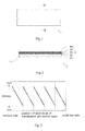
- Fig. 1 is a plan view of a transparent gas barrier film
- Fig. 2 is a sectional view obtained by cutting the film in the thickness direction.
- a transparent gas barrier film 1 includes a transparent gas barrier layer 3 on a resin substrate 2.
- the transparent gas barrier layer 3 includes first to fifth deposited layers 31, 32, 33, 34, and 35 each continuously changing in density in the thickness direction.
- the densities of the first to fifth deposited layers 31 to 35 are each continuously and periodically changed in the thickness direction.
- the densities of the deposited layers 31 to 35 are changed from a higher density to a lower density or from a lower density to a higher density in the thickness direction.
- the transparent gas barrier layer 3 is composed of five layers: first to fifth deposited layers 31 to 35, but the present invention is not limited thereto.
- the transparent gas barrier layer may be composed of two layers or three or more layers each continuously changing in density in the thickness direction (none of which is illustrated).
- the transparent gas barrier layer 3 may include a layer which does not continuously change in density as long as the transparent gas barrier layer 3 includes a plurality of layers each continuously changing in density in the thickness direction.
- Figs. 3 and 4 are schematic views each illustrating an example of a density distribution in the thickness direction of the gas barrier layer in the transparent gas barrier film. These schematic views also illustrate a transparent gas barrier layer formed of five layers (first to fifth deposited layers), but the number of deposited layers is not limited thereto.
- the deposited layers that form the transparent gas barrier layer each gradually increase in density from the resin substrate toward the surface side of the transparent gas barrier layer. Therefore, the transparent gas barrier layer has a repetition of patterns in which the density is gradually increased (from lower density to higher density) in the thickness direction.
- the deposited layers that form the transparent gas barrier layer each gradually decrease in density from the resin substrate toward the surface side of the transparent gas barrier layer. Therefore, the transparent gas barrier layer has a repetition of patterns in which the density is gradually decreased (from higher density to lower density) in the thickness direction.
- the change in density may be linear or curved.
- the densities of the deposited layers may be the same or different as long as they are continuously changed.
- the density gradients of the deposited layers may be the same or different.
- a high gas barrier property can be obtained by forming a high-density layer, but when the thickness of the high-density layer is increased or the layer and an another layer is laminated to form a laminated structure, internal stress increases, leading to generation of microcracks, so that the gas barrier property is easily deteriorated.
- the transparent gas barrier film of the present invention can resist generation of microcracks, so that a high gas barrier property can be achieved.
- the reason why such a high gas barrier property can be achieved is not clear, but a change in density with a certain layer thickness tends to reduce stress as compared to a change in density with a random layer thickness.
- the ratio (Y/X) of a maximum value (Y) to a minimum value (X) of the density in the transparent gas barrier layer is preferably 1.1 or more.
- the ratio of Y to X is close to 1, so that a difference therebetween is small, any of gas barrier property improvement and internal stress reduction functions may become insufficient.
- the density of the transparent gas barrier layer varies depending on a formation material, a composition, and a formation method thereof, for example, the density of the transparent gas barrier layer is 1.6 to 2.2 g ⁇ cm -3 when the material is silicon oxide, and is 2.3 to 2.7 g ⁇ cm -3 when the material is silicon nitride.
- the thickness of the transparent gas barrier layer is preferably 1 ⁇ m or less, more preferably in a range of 100 nm to 800 nm, further preferably in a range of 200 nm to 500 nm.
- the thicknesses of the deposited layers changing in density in the thickness direction are, each independently, preferably in a range of 50 nm to 200 nm, more preferably in a range of 10 nm to 100 nm.
- the thicknesses of the deposited layers may be the same, or each independently different, but preferably, the deposited layers are formed in the same thickness.
- the number of the deposited layers changing in density in the thickness direction is 2 or more, preferably in a range of 3 to 20, more preferably in a range of 5 to 16.
- the resin substrate is flexible.
- the flexible resin substrate is a flexible sheet-shaped article which can be wound around a roll.
- a transparent resin substrate is used for the resin substrate.
- the resin substrate it is preferred to use a substrate having high heat resistance, particularly a substrate which has a high Tg (glass transition temperature) and is hard to be thermally shrunk in consideration of influences of heating by radiant heat from a plasma or deposition source.
- Tg glass transition temperature
- a transparent film having high heat resistance is used as the resin substrate.
- the resin film is preferably a resin film having a shrinkage factor of 0.5% or lower in both a short direction (TD) and a long direction (MD).
- the resin film include transparent films composed of cycloolefin polymers, polyethylene naphthalate, polyethylene sulfide, polyphenyl sulfide, polycarbonate, polyimide, polyamide, and the like.
- the thickness of the resin substrate is preferably 20 ⁇ m to 200 ⁇ m, particularly preferably 50 ⁇ m to 150 ⁇ m from the viewpoint of handling.
- the width of the resin substrate is not particularly limited, but is preferably 50 mm or less, for example.
- the resin substrate may be subjected to a surface modifying treatment such as a corona discharge treatment, a plasma discharge treatment, or an ion etching (RIE) treatment on a surface thereof (a surface to be provided with a transparent gas barrier layer).
- a surface modifying treatment such as a corona discharge treatment, a plasma discharge treatment, or an ion etching (RIE) treatment on a surface thereof (a surface to be provided with a transparent gas barrier layer).
- RIE ion etching
- the surface of the resin substrate may be provided with an inorganic substance layer or a polymer layer as a smooth layer and an adhesive layer.
- a transparent gas barrier film obtained by the production method and production apparatus of the present invention can be used for various applications.
- the transparent gas barrier film of the present invention has an excellent gas barrier property and good flexibility, and therefore can be suitably used as a constituent member of various kinds of electronic devices.
- the transparent gas barrier film of the present invention can be used for a support substrate or a sealing member of an organic EL device; a coating film of a solar cell; a coating film of a thin film battery; and so on.
- the organic EL device 100 as illustrated in Fig. 5 includes a support substrate 110, an organic EL layer 120, and a sealing layer 130.
- the organic EL (organic electroluminescence) layer 120 is composed of a laminate having a first electrode layer 121 provided on the support substrate 110, an organic layer 122 including a light emitting layer provided on the first electrode 121, and a second electrode layer 123 provided on the organic layer 122.
- the sealing member 130 is provided on the laminate (on the second electrode 123).
- a transparent gas barrier film of the present invention can be used as at least one of the support substrate 110 and the sealing member 130.
- the first electrode layer is, for example, an anodic layer, although it may be either anodic or cathodic.
- the anodic layer include transparent electrode layers such as ITO (Indium Tin Oxide) and IZO (registered trademark; Indium Zinc Oxide).
- the organic layer includes a light-emitting layer, and includes at least one selected from a hole injection layer, a hole transport layer, an electron transport layer, and an electron injection layer as necessary.
- the second electrode layer is, for example, a cathodic layer, although it may be either cathodic or anodic. Examples of the cathodic layer include an aluminum layer, a magnesium/aluminum layer, and a magnesium/silver layer.
- the sealing member may have a monolayer structure, or a multi-layer structure.
- the transparent gas barrier film of the present invention is used for at least one layer thereof.
- an organic EL device having an excellent gas barrier property can be formed by fixing the transparent gas barrier film to the laminate using fixation means such as an adhesive or heat seal.
- the organic EL device When the transparent gas barrier film of the present invention is used as a support substrate of the organic EL device, the organic EL device can be made lighter, thinner and more flexible.
- the organic EL device using the transparent gas barrier film of the present invention as a support substrate serves as a flexible display, and can be used in the form of an electronic paper when rolled, for example.
- the transparent gas barrier film of the present invention is used as a sealing member, an organic EL layer is easily sealed, and a thin organic EL device can be obtained.
- the solar cell includes a solar battery cell, and the solar battery cell is coated with the transparent gas barrier film of the present invention.
- the transparent gas barrier film can also be suitably used as a light-receiving-side front sheet and a protecting back sheet of a solar cell.
- One example of the structure of the solar cell is a structure in which a solar battery cell formed of a silicon thin film or a CIGS (Copper Indium Gallium DiSelenide) thin film is sealed with a resin of an ethylene-vinyl acetate copolymer etc., and further caught by the transparent gas barrier film of the present invention. Sealing with the resin may be omitted to catch the solar battery cell directly by the transparent gas barrier film of the present invention.
- the thin film battery includes a laminate including a current-collecting layer, an anodic layer, a solid electrolyte layer, a cathodic layer, and a current-collecting layer in this order, and the laminate is coated with the transparent gas barrier film of the present invention.
- the thin film battery include thin film lithium ion batteries.
- a current-collecting layer provided on a substrate and composed of a metal an anodic layer composed of a metal inorganic film, a solid electrolyte layer, a cathodic layer, and a current-collecting layer composed of a metal are laminated in this order.
- the transparent gas barrier film of the present invention can also be used as a substrate of the thin film battery.
- the production method of the transparent gas barrier film includes depositing a plurality of layers on a long belt-shaped resin substrate by alternately passing the long belt-shaped resin substrate through a deposition area in which a material containing at least one of metals and semimetals is deposited by generating a plasma and a non-deposition area in which the material is not deposited.
- a transparent gas barrier layer including a plurality of layers each continuously changing in density in the thickness direction is formed on the resin substrate by changing a distance between the resin substrate and a plasma source.
- a plurality of layers each continuously changing in density in the thickness direction can be laminated on a surface of the resin substrate.
- the change in distance between the resin substrate and the plasma source is preferably at least one of a change to increase the distance between the resin substrate and the plasma source and a change to decrease the distance between the resin substrate and the plasma source.
- the at least one of metals and semimetals is preferably at least one selected from the group consisting of an oxide, a nitride, a carbide, a nitride oxide, a carbide oxide, a carbide nitride, and a carbide nitride oxide.
- the WVTR of a transparent gas barrier film obtained by the production method of the present invention is 0.01 g ⁇ m -2 ⁇ day -1 or less, preferably 0.001 g ⁇ m -2 ⁇ day -1 or less.
- the production apparatus of the present invention is used for carrying out the production method.
- the production apparatus of the present invention is an apparatus that is applied for producing a transparent gas barrier film including a transparent gas barrier layer including a plurality of layers each continuously changing in density in the thickness direction.
- the production apparatus includes a chamber having a deposition area and a non-deposition area; a plasma source that generates a plasma; a deposition source containing a material including at least one of metals and semimetals; and a conveyor that feeds a long belt-shaped resin substrate, and further preferably includes a reaction gas supply device that supplies a reaction gas into the chamber.
- the plasma source and the deposition source are provided in the chamber.
- the conveyor is configured to cause the resin substrate to pass through the deposition area and the non-deposition area alternately and feed the resin substrate so as to go away from or get closer to the plasma source when the resin substrate passes through the deposition area.
- the production method and the production apparatus of the first embodiment have the following aspect: by feeding a long belt-shaped resin substrate so as to draw a helical conveyance track using one guide roller, a plurality of deposited layers are sequentially laminated on a surface of the resin substrate while the resin substrate is caused to pass through a deposition area and a non-deposition area alternately.
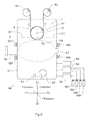
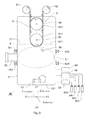
- Figs. 6 and 7 illustrate an example of a configuration of the production apparatus of the first embodiment.
- a direction orthogonally crossing a horizontal plane is referred to as a "Z direction”
- a direction orthogonally crossing the Z direction is referred to as an "X direction”
- a direction orthogonally crossing the Z direction and X direction is referred to as a "Y direction” for the sake of convenience.
- one side in the X direction is referred to as an "X1 side” and the opposite side in the X direction (side opposite to the one side) is referred to as an "X2 side”
- one side in the Y direction is referred to as a “Y1 side” and the opposite side in the Y direction (side opposite to the one side) is referred to as a "Y2 side”
- one side in the Z direction is referred to as a "Z1 side” and the opposite side in the Z direction (side opposite to the one side) is referred to as a "Z2 side”.
- Fig. 6 is a front view of the production apparatus seen from the X2 side in the X direction (direction from X2 to X1)
- Fig. 7 is a left side view of the production apparatus seen from the Y1 side in the Y direction (direction from Y1 to Y2).
- a production apparatus 4A includes a chamber 51, the inside of which can be held in vacuum; a conveyor 7 that continuously feeds a long belt-shaped resin substrate 8; a plasma source 52 that generates a plasma; a deposition source 53 containing a material to be deposited; a reaction gas supply device 54 that supplies a reaction gas into the chamber 51; a discharge gas supply device 55 that supplies a discharge gas into the chamber 51; and a vacuum pump 56 that brings the inside of the chamber 51 into a vacuum state.
- the principal part of the conveyor 7 is provided in the chamber 51, and the plasma source 52 and the deposition source 53 are provided in the chamber 51.
- a partition wall 511 that separates the deposition area and the non-deposition area from each other is provided.
- the deposition area is one region in the chamber 51, at which a material can be deposited on an adherend (i.e. long belt-shaped resin substrate 8).
- the non-deposition area is the other region in the chamber 51, at which a material is not deposited on an adherend.
- a region on the Z2 side (lower side) with respect to the partition wall 511 is the deposition area
- a region on the Z1 side (upper side) with respect to the partition wall 511 is the non-deposition area.
- partition wall 511 it is not necessarily required to provide the partition wall 511, and it is also possible to omit the partition wall 511.
- the plasma is not particularly limited, and for example, an arc discharge plasma, a glow discharge plasma, or the like may be used.
- An arc discharge plasma is preferably used because a very high electron density is achieved unlike a glow discharge plasma.
- reactivity of a material can be enhanced, so that a very dense transparent gas barrier layer can be formed on a resin substrate.
- arc discharge plasma generation source for example, a pressure gradient type plasma gun, a direct-current discharge plasma generator, a high-frequency discharge plasma generator, or the like may be used.
- a pressure gradient type plasma gun is preferably used as the plasma source 52 because a high-density plasma can be stably generated during deposition.
- a pressure gradient type plasma gun is used as the plasma source 52.
- the plasma source 52 is provided in, for example, a first side wall (side wall on the Y1 side) of the chamber 51 as illustrated in Fig. 6 .
- a reflection electrode 57 is provided to face the pressure gradient type plasma gun. Focusing electrodes 581, 582, 583, and 584 are provided on the circumference of the plasma source 52 and the circumference of the reflection electrode 57.
- the plasma source 52 is controlled so that a plasma beam 9 is applied toward the reflection electrode 57, and the plasma beam 9 is formed into a necessary shape by the focusing electrodes 581, 582, 583, and 584.
- the plasma density is higher at a position closer to the plasma source 52, and is lower at a position farther from the plasma source 52.
- the plasma density increases as going toward the Y1 side, and the plasma density decreases as going toward the Y2 side. Therefore, the deposition area in the chamber 51 has a part with the highest plasma density and a part with the lowest plasma density.
- the part with the highest plasma density is positioned in the vicinity of the plasma source 52, and the part with the lowest plasma density is positioned in the vicinity of the reflection electrode 57.
- a virtual line connecting the part with the highest plasma density and the part with the lowest plasma density is parallel to the Y direction.
- the deposition source 53 is installed on the bottom of the chamber 51 so as to face the conveyor 7. A material to be deposited is placed on the upper surface of the deposition source 53.
- the plasma may be used, but resistance heating or an electron beam may also be used.
- the material placed in the deposition source 53 can be appropriately selected from a metal, a semimetal, and an oxide, a nitride, a carbide, a nitride oxide, a carbide oxide, a carbide nitride, and a carbide nitride oxide thereof.
- a deposited layer can be formed while a component of the reaction gas is introduced into the material in the deposition source 53.
- the deposited layer composed of an oxide, a nitride, a carbide, a nitride oxide, a carbide oxide, a carbide nitride, or a carbide nitride oxide can also be formed by depositing the material with a plasma generated in the presence of a reaction gas.
- the foregoing oxide, nitride, carbide, nitride oxide, carbide oxide, carbide nitride, or carbide nitride oxide may be used as the material placed in the deposition source 53.
- the reaction gas supply device 54 is provided on, for example, the second side wall of the chamber 51.
- the same number of reaction gas storage cylinders 541, 542, and 543 as the number of reaction gases are connected to the reaction gas supply device 54, and the reaction gas supply device 54 supplies a reaction gas at an appropriate pressure into the chamber 51.
- Examples of the reaction gas include oxygen-containing gas, nitrogen-containing gas, hydrocarbon-containing gas, and mixture of these gases.
- oxygen-containing gas include oxygen (O 2 ), dinitrogen monoxide (N 2 O), and nitric oxide (NO)
- examples of nitrogen-containing gas include nitrogen (N 2 ), anmonia (NH 3 ), and nitric oxide (NO)
- examples of hydrocarbon-containing gas include methane (CH 4 ), ethane (C 2 H 6 ), propane (C 3 H 8 ), butane (C 4 H 10 ), ethylene (C 2 H 4 ), and acethylene (C 2 H 2 ).
- the discharge gas supply device 55 is provided on, for example, the second side wall of the chamber 51.
- a discharge gas storage cylinder 551 is connected to the discharge gas supply device 55, and the discharge gas supply device 55 supplies a discharge gas at an appropriate pressure into the chamber 51.
- the discharge gas typically an inert gas such as an argon gas may be used.
- the vacuum pump 56 is provided on, for example, the second side wall of the chamber 51. By actuating the vacuum pump 56, the inside of the chamber 51 can be evacuated into a vacuum state.
- the conveyor 7 conveys the long belt-shaped resin substrate 8 in its long direction by so called a roll-to-roll method.
- the conveyor 7 helically conveys the resin substrate 8, and guides the resin substrate 8 to the deposition area and the non-deposition area alternately.
- the conveyor 7 in this embodiment has one guide roller 71 for feeding the long belt-shaped resin substrate 8 in the long direction while drawing a helical track.
- the lower part of the guide roller 71 is exposed to the deposition area for guiding the resin substrate 8 to the deposition area.
- the long belt-shaped resin substrate 8 is helically wound around the circumferential surface of the guide roller 71 from the X1 side to the X2 side. Therefore, the resin substrate 8 helically wound around the guide roller 71 passes through the deposition area at the lower part of the guide roller 71, and passes through the non-deposition area at the upper part of the guide roller 71.
- the guide roller 71 is a cylindrical roller centering on a shaft 72.
- a direction along which the shaft 72 extends (axis direction) is parallel to the X direction. Therefore, the shaft 72 is extended in a direction which orthogonally crosses the direction of the virtual line connecting the part with the highest plasma density and the part with the lowest plasma density (Y direction).
- the guide roller 71 may be configured to be able to rotate about the shaft 72, or may be fixed to the shaft 72.
- a guide groove or a guide projection (not illustrated) etc. may be formed on the circumferential surface of the guide roller 71.
- the resin substrate 8 is wound around the guide roller 71 so that the resin substrate 8 intermittently passes through the deposition area five times while being helically conveyed.
- a crystal monitor 59 for measuring and controlling the deposition rate is provided in the vicinity of the resin substrate 8 passing through the deposition area.
- the crystal monitor 59 is provided at five locations at equal intervals in correspondence with the number of times the resin substrate 8 enters the deposition area.
- a temperature controller (not illustrated) may be attached to the guide roller 71 as necessary.
- the temperature controller is provided for adjusting the surface temperature of the guide roller 71.
- Examples of the temperature controller include a heat medium circulation device for circulating silicone oil etc.
- the long belt-shaped resin substrate 8 drawn out from a roll 81 on the upstream side is fed from the Z1 side to the Z2 side, wound around the lower circumferential surface of the guide roller 71, then fed from the Z2 side to the Z1 side, and wound around the upper circumferential surface of the guide roller 71 while being slightly inclined.
- the resin substrate 8 is fed from the Y1 side to the Y2 side (in Y direction).
- the resin substrate 8 is fed from the Y2 side to the Y1 side (in Y direction).
- the long belt-shaped resin substrate 8 is wound around the upper circumferential surface of the guide roller 71, and then similarly fed from the lower circumferential surface to the upper circumferential surface of the guide roller 71 in succession while drawing a helical track. Therefore, the resin substrate 8 is fed while drawing a helical track clockwise as a whole as seen from the X1 side, and wound around a roll 82 on the downstream side. Accordingly, the conveyor 7 is configured to feed the resin substrate 8 while passing the resin substrate 8 through the deposition area and the non-deposition area alternately.
- Conveyance of the resin substrate 8 wound around the guide roller 71 is performed by, for example, unwinding operations of the roll 81 on the upstream side and winding operations of the roll 82 on the downstream side.
- the resin substrate 8 passes through the deposition area, the resin substrate 8 is fed in the Y direction (from the Y1 side to the Y2 side) as illustrated in Fig. 6 .
- the resin substrate 8 is fed so as to go away from the plasma source 52 at the time of passing the resin substrate 8 through the deposition area.
- a method for producing a transparent gas barrier film will now be described.
- a method for producing a transparent gas barrier film using the production apparatus 4A illustrated in Figs. 6 and 7 will be described, but the production method of the present invention is not limited to production using the production apparatus 4A.
- the inside of the chamber 51 is kept in a vacuum state.
- the pressure of the inside of the chamber 51 in formation of a deposited layer on the resin substrate 8 falls within a range of 0.01 Pa to 0.1 Pa, preferably 0.02 Pa to 0.05 Pa.
- a discharge gas is introduced from the discharge gas supply device 55 into a pressure gradient type plasma gun as the arc discharge plasma generation source 52, and a constant voltage is applied to apply a plasma toward the reflection electrode 57.
- the shape of the plasma beam 9 is controlled to necessary shape by the focusing electrodes 581, 582, 583 and 584.
- the power of the arc discharge plasma is, for example, 1 to 10 kW.
- a reaction gas is introduced into the chamber 51 from the reaction gas supply device 54.
- a material placed in the deposition source 53 is irradiated with, for example, an electron beam 531 to evaporate the material toward the resin substrate 8.
- reaction gas and generation of the plasma may be performed in parallel, or the plasma may be generated after introduction of the reaction gas, or the reaction gas may be introduced after generation of the plasma.
- the reaction gas is only required to exist in the deposition area during formation of a transparent gas barrier layer.
- an opening/closing shutter (not illustrated) is provided between the deposition source 53 and the resin substrate 8 beforehand, the shutter is closed after the start of evaporation of the material until the deposition rate is stabilized, and after the deposition rate is stabilized, the shutter is opened to deposit the material on the resin substrate 8.
- the deposition rate of the material can be appropriately set, and is, for example, 10 to 300 nm/minute.
- the long belt-shaped resin substrate 8 is drawn out from the roll 81 on the upstream side, and introduced into the chamber 51.
- rolls 81 and 82 are disposed outside the chamber 51, but may be disposed on the non-deposition area in the chamber 51.
- the length of the long belt-shaped resin substrate 8 in the short direction is not particularly limited, and it can be appropriately set, and is, for example, several mm to 1000 mm, preferably several mm to 50 mm.
- the length of the long belt-shaped resin substrate 8 in the short direction is set to, for example, several mm to 100 mm, preferably several mm to about 50 mm.
- the resin substrate 8 is wound around the guide roller 71 of the conveyor 7, and the resin substrate 8 is fed so as to draw a helical track, and caused to pass through the deposition area and the non-deposition area alternately.
- the conveyance speed of the resin substrate 8 can be appropriately set in consideration of the deposition rate and the thickness of a deposited layer formed etc., and is, for example, 0.1 to 20 m/minute.
- the material is deposited on the resin substrate 8, so that deposited layers are formed one after another.
- the resin substrate 8 moves from the Y1 side to the Y2 side, and therefore goes away from the plasma source 52. Therefore, in the deposition area, the distance between the resin substrate 8 and the plasma source 52 is changed (changed to increase the distance in this case), so that a plurality of deposited layers each continuously changing in density in the thickness direction can be formed.
- the surface temperature of the resin substrate 8 is set to, for example, 20°C to 200°C, preferably 80°C to 150°C.
- the material is deposited on a surface of the resin substrate 8 to form a first deposited layer.
- the resin substrate 8 is fed so as to go away from the plasma source 52, the density of the material contained in the deposited layer gradually decreases.
- a first deposited layer 31 is formed in which the density on the surface side of the resin substrate 8 is the highest, and the density decreases as going away from the resin substrate 8 as illustrated in Fig. 8 .
- the resin substrate 8 provided with the first deposited layer 31 passes through the non-deposition area by way of the upper circumferential surface of the guide roller 71, and is then guided to the deposition area by passing over the circumferential surface of the guide roller 71 again. At this time, the material is deposited on the surface of the first deposited layer 31 to form a second deposited layer 32. Similarly to the first deposited layer 31, the second deposited layer 32 continuously decreases in density as going away from the resin substrate 8.
- a transparent gas barrier layer including a plurality of deposited layers 31 to 35 (five layers in the illustrated example) each continuously changing in density in the thickness direction can be formed on the resin substrate 8.
- a deposited layer is formed each time the resin substrate 8 passes through the deposition area. Therefore, the number of deposited layers formed is identical to the number of times the resin substrate passes through the deposition area.
- a plurality of deposited layers can be continuously formed on the long belt-shaped resin substrate 8 using a roll-to-roll method, so that a transparent gas barrier film including a plurality of layers each continuously changing in density in the thickness direction can be efficiently produced.
- a transparent gas barrier film has a plurality of layers each continuously changing in density in the thickness direction, and therefore has an excellent gas barrier property and very low internal stress.
- a transparent gas barrier film including a plurality of deposited layers having substantially the same density distribution and density gradient as illustrated in Fig. 3 or 4 can be formed.
- an apparatus and a method which are capable of forming a plurality of deposited layers each continuously decreasing in density as going away from a surface of the resin substrate 8 as illustrated in Fig. 4 , are illustrated as an example, but a plurality of deposited layers each continuously increasing in density as going away from a surface of the resin substrate 8 as illustrated in Fig. 3 can also be formed.
- These deposited layers can be obtained by, for example, modifying the production apparatus 4A as described in (1) or (2) below.
- the production method and the production apparatus of the second embodiment have the following aspect: by feeding a long belt-shaped resin substrate so as to draw a helical conveyance track using a plurality of pairs of guide rollers, a plurality of deposited layers are sequentially laminated on a surface of the resin substrate while the resin substrate is caused to pass through a deposition area and a non-deposition area alternately.
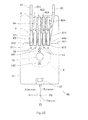
- Fig. 9 is a front view of the production apparatus of the second embodiment seen from the X2 side in the X direction
- Fig. 10 is a left side view of the production apparatus seen from the Y1 side in the Y direction.
- the production apparatus 4B includes a chamber 51, a conveyor 6, a plasma source 52, a reflection electrode 57, focusing electrodes 581, 582, 583, and 584, a deposition source 53, a reaction gas supply device 54, a discharge gas supply device 55, and a vacuum pump 56.
- a conveyor 6 of this embodiment is similar to the conveyor 7 of the first embodiment in that the long belt-shaped resin substrate 8 is conveyed in its long direction by a roll-to-roll method, but the conveyor 6 has a conveyance mechanism different from that in the first embodiment.
- the conveyor 6 has a plurality of guide rollers 611 and 612 for feeding the long belt-shaped resin substrate 8 in the long direction. Some of the plurality of guide rollers are provided in the deposited area for guiding the resin substrate 8 to the deposition area.
- the conveyor 6 helically conveys the resin substrate 8, and guides the resin substrate 8 to the deposition area and the non-deposition area alternately.
- the conveyor 6 has a basic configuration in which there are a plurality of pairs of guide rollers 611 and 621 that can be rotated so as to feed the long belt-shaped resin substrate 8 in its long direction as illustrated in Figs. 9 and 10 .
- the guide roller disposed in the deposition area is referred to as an "inside guide roller” and the guide roller disposed in the non-deposition area is referred to as an “outside guide roller” for the sake of convenience, and prefixes of "first”, “second” and so on are added for distinguishing a plurality of guide rollers.
- the production apparatus 4B in the illustrated example is an apparatus capable of laminating first to fifth deposited layers on the resin substrate 8, in which the number of the deposited layers is the same as the number of the inside guide rollers (first to fifth inside guide rollers 611, 612, 613, 614, and 615) provided in the deposition area.
- the inside guide rollers 611,... (first to fifth inside guide rollers 611 to 615) provided in the deposition area may be wholly included within the deposition area, or may be disposed so as to be partially included within the deposition area as illustrated in the figure.
- outside guide rollers 621,... are disposed on the Z1 side with respect to the inside guide rollers 611, and the number thereof is smaller by 1 than the number of the inside guide rollers 611.
- rollers having the same diameter and width can be used.
- rollers having the same diameter and width can be used.
- the first to fifth inside guide rollers 611 to 615 are rotatably attached to a shaft 63, and the first to fourth outside guide rollers 621 to 624 are rotatably attached to a shaft 64.
- Directions along which the shafts 63 and 64 extend are both parallel to the X direction. Therefore, the shafts 63 and 64 are extended in a direction which orthogonally crosses the direction of the virtual line connecting the part with the highest plasma density and the part with the lowest plasma density (Y direction).
- the first to fifth inside guide rollers 611 to 615 are arranged side by side at necessary intervals on the shaft 63, and the first to fourth outside guide rollers 621 to 624 are similarly arranged side by side at necessary intervals on the shaft 64.
- the interval between adjacent inside guide rollers 611 is preferably as small as possible because the apparatus can be made smaller, and a plurality of deposited layers having a relatively uniform density distribution and density gradient can be formed.
- the first to fourth outside guide rollers 621 to 624 are rotatably attached to the shaft 64 while being slightly inclined with respect to the shaft 64 for helically feeding the resin substrate 8 to each guide roller.
- a crystal monitor 59 for measuring and controlling the deposition rate is provided in the vicinity of each of the first to fifth inside guide rollers 611 to 615.
- a temperature controller (not illustrated) may be attached to each of the first to fifth inside guide rollers 611 to 615 as necessary.
- the temperature controller is provided for adjusting the surface temperature of the inside guide roller 611.
- Examples of the temperature controller include a heat medium circulation device for circulating silicone oil etc.
- the long belt-shaped resin substrate 8 drawn out from the roll 81 on the upstream side is fed from the Z1 side to the Z2 side, wound around the lower circumferential surface of the first inside guide roller 611, then fed from the Z2 side to the Z1 side, and wound around the upper circumferential surface of the first outside guide roller 621.
- the resin substrate 8 is fed from the Y1 side to the Y2 side (in Y direction).
- the resin substrate 8 is fed from the Y2 side to the Y1 side (in Y direction).
- the long belt-shaped resin substrate 8 is wound around the upper circumferential surface of the first outside guide roller 621, then similarly wound around the second inside guide roller 612, the second outside guide roller 622, the third inside guide roller 613, the third outside guide roller 623, the fourth inside guide roller 614, the fourth outside guide roller 624, and the fifth inside guide roller 615 in this order, then fed from the Z2 side to the Z1 side, and wound around the roll 82 on the downstream side.
- the resin substrate 8 is fed while drawing a helical track clockwise as a whole as seen from the X1 side. That is, the resin substrate 8 is helically fed through a plurality of the inside guide rollers 611,... and the outside guide rollers 621,... provided in the deposition area and the non-deposition area as described above. Accordingly, the conveyor 6 is configured to feed the resin substrate 8 while passing the resin substrate 8 through the deposition area and the non-deposition area alternately.
- the resin substrate 8 passes through the deposition area, the resin substrate 8 is fed in the Y direction (from the Y1 side to the Y2 side) as illustrated in Fig. 9 .
- the resin substrate 8 is fed so as to go away from the plasma source 52 at the time of passing the resin substrate 8 through the deposition area.
- a method for producing a transparent gas barrier film will now be described.
- a method for producing a transparent gas barrier film using the production apparatus 4B illustrated in Figs. 9 and 10 will be described, but the production method of the present invention is not limited to production using the production apparatus 4B.
- the deposition area in the chamber 51 is arranged so that a material can be deposited on an adherend.
- the long belt-shaped resin substrate 8 is drawn out from the roll 81 on the upstream side, and introduced into the chamber 51.
- rolls 81 and 82 are disposed outside the chamber 51, but may be disposed on the non-deposition area in the chamber 51.
- the resin substrate 8 is wound around the guide rollers 611 and 621 of the conveyor 6, and the resin substrate 8 is fed so as to draw a helical track, and caused to pass through the deposition area and the non-deposition area alternately.
- the conveyance speed of the resin substrate 8 can be appropriately set in consideration of the deposition rate and the thickness of a deposited layer formed etc., and is, for example, 0.1 to 20 m/minute.
- the material is deposited on the resin substrate 8, so that deposited layers are formed one after another.
- the resin substrate 8 moves from the Y1 side to the Y2 side, and therefore goes away from the plasma source 52. Therefore, in the deposition area, the distance between the resin substrate 8 and the plasma source 52 is changed (changed to increase the distance in this case), so that a plurality of deposited layers each continuously changing in density in the thickness direction can be formed.
- the surface temperature of the resin substrate 8 is set to, for example, 20°C to 200°C, preferably 80°C to 150°C.
- the material is deposited on a surface of the resin substrate 8 to form a first deposited layer.
- the resin substrate 8 is fed so as to go away from the plasma source 52, the density of the material contained in the deposited layer gradually decreases.
- a first deposited layer 31 is formed in which the density on the surface side of the resin substrate 8 is the highest, and the density decreases as going away from the resin substrate 8 as illustrated in Fig. 8 .
- the second to fifth deposited layers 32 to 35 each changing in density are sequentially formed on the surface of the first deposited layer 31. Accordingly, a transparent gas barrier layer including a plurality of deposited layers 31 to 35 each continuously changing in density in the thickness direction can be formed on the resin substrate 8. In this way, a deposited layer is formed each time the resin substrate 8 passes through the deposition area.
- the number of deposited layers formed is identical to the number of inside guide rollers.
- the production apparatus and the production method of this embodiment are also capable of efficiently producing a transparent gas barrier film including a plurality of layers each continuously changing in density in the thickness direction.
- an apparatus and a method for forming a plurality of deposited layers each continuously decreasing in density as going away from a surface of the resin substrate 8 are illustrated as an example, but a plurality of deposited layers each continuously increasing in density as going away from a surface of the resin substrate 8 can also be formed.
- These deposited layers may be formed by, for example, making modifications as described in (1) or (2) in the first embodiment.
- a plurality of inside guide rollers 611. having the same diameter are used, but rollers having different diameters (not illustrated) may also be used for some of the inside guide rollers.
- guide rollers having a small diameter are used as the first to third inside guide rollers 611, 612, and 613, and guide rollers having a large diameter are used as the fourth to fifth inside guide rollers 614 and 615.
- comparison between passage of the resin substrate over the lower circumferential surface of the inside guide roller having a large diameter and passage of the resin substrate over the lower circumferential surface of the inside guide roller having a small diameter shows that when passing over the lower circumferential surface of the inside guide roller having a large diameter, the resin substrate 8 passes through the deposition area over a long time, so that a deposited layer having a large thickness can be formed.
Landscapes
- Chemical & Material Sciences (AREA)
- Engineering & Computer Science (AREA)
- Chemical Kinetics & Catalysis (AREA)
- Materials Engineering (AREA)
- Mechanical Engineering (AREA)
- Metallurgy (AREA)
- Organic Chemistry (AREA)
- Physics & Mathematics (AREA)
- Optics & Photonics (AREA)
- General Chemical & Material Sciences (AREA)
- Manufacturing & Machinery (AREA)
- Plasma & Fusion (AREA)
- Physical Vapour Deposition (AREA)
- Electroluminescent Light Sources (AREA)
- Laminated Bodies (AREA)
- Chemical Vapour Deposition (AREA)
Applications Claiming Priority (2)
| Application Number | Priority Date | Filing Date | Title |
|---|---|---|---|
| JP2013023298A JP2014154361A (ja) | 2013-02-08 | 2013-02-08 | 透明ガスバリアフィルムの製造方法、透明ガスバリアフィルムの製造装置、及び有機エレクトロルミネッセンスデバイス |
| PCT/JP2014/051187 WO2014122987A1 (fr) | 2013-02-08 | 2014-01-22 | Procédé de fabrication d'un film transparent faisant barrière aux gaz, dispositif de fabrication d'un film transparent faisant barrière aux gaz, et dispositif électroluminescent organique |
Publications (1)
| Publication Number | Publication Date |
|---|---|
| EP2955245A1 true EP2955245A1 (fr) | 2015-12-16 |
Family
ID=51299584
Family Applications (1)
| Application Number | Title | Priority Date | Filing Date |
|---|---|---|---|
| EP14749069.2A Withdrawn EP2955245A1 (fr) | 2013-02-08 | 2014-01-22 | Procédé de fabrication d'un film transparent faisant barrière aux gaz, dispositif de fabrication d'un film transparent faisant barrière aux gaz, et dispositif électroluminescent organique |
Country Status (7)
| Country | Link |
|---|---|
| US (1) | US20150333289A1 (fr) |
| EP (1) | EP2955245A1 (fr) |
| JP (1) | JP2014154361A (fr) |
| KR (1) | KR20150116765A (fr) |
| CN (1) | CN104364415A (fr) |
| TW (1) | TW201441394A (fr) |
| WO (1) | WO2014122987A1 (fr) |
Families Citing this family (6)
| Publication number | Priority date | Publication date | Assignee | Title |
|---|---|---|---|---|
| TWI501873B (zh) * | 2011-12-27 | 2015-10-01 | Nitto Denko Corp | Transparent gas barrier film, transparent gas barrier film manufacturing method, organic EL element, solar cell and thin film battery |
| JP2014152362A (ja) * | 2013-02-08 | 2014-08-25 | Nitto Denko Corp | 透明ガスバリアフィルムの製造方法、及び透明ガスバリアフィルムの製造装置 |
| JP2016094629A (ja) * | 2014-11-12 | 2016-05-26 | 東レエンジニアリング株式会社 | 基材搬送処理装置 |
| JP6784969B2 (ja) * | 2015-10-22 | 2020-11-18 | 天馬微電子有限公司 | 薄膜デバイスとその製造方法 |
| JP2019515430A (ja) * | 2016-04-25 | 2019-06-06 | アプライド マテリアルズ インコーポレイテッドApplied Materials,Incorporated | バッテリ用途のセパレータ製作のための方法及び装置 |
| NL2027074B1 (en) * | 2020-12-08 | 2022-07-07 | Kalpana Tech B V | Roll-to-roll processing |
Family Cites Families (12)
| Publication number | Priority date | Publication date | Assignee | Title |
|---|---|---|---|---|
| US6083628A (en) | 1994-11-04 | 2000-07-04 | Sigma Laboratories Of Arizona, Inc. | Hybrid polymer film |
| JPH08164595A (ja) | 1994-12-15 | 1996-06-25 | Toppan Printing Co Ltd | 透明積層フィルム |
| JP2004151528A (ja) | 2002-10-31 | 2004-05-27 | Bridgestone Corp | 薄膜表示素子保護用バリヤー膜 |
| JP4472962B2 (ja) | 2003-10-02 | 2010-06-02 | ヒラノ光音株式会社 | 表面処理装置 |
| US8652625B2 (en) * | 2004-09-21 | 2014-02-18 | Konica Minolta Holdings, Inc. | Transparent gas barrier film |
| JP4954574B2 (ja) | 2006-03-02 | 2012-06-20 | 日東電工株式会社 | 透明ガスバリア性フィルムの製造方法および透明ガスバリア性フィルムの製造装置 |
| JP4941149B2 (ja) | 2007-07-23 | 2012-05-30 | 凸版印刷株式会社 | ガスバリア性積層フィルム |
| JP2009209438A (ja) | 2008-03-06 | 2009-09-17 | Panasonic Corp | 薄膜形成装置 |
| WO2010100971A1 (fr) * | 2009-03-04 | 2010-09-10 | コニカミノルタホールディングス株式会社 | Matériau de base comportant un film mince |
| EP2360293A1 (fr) * | 2010-02-11 | 2011-08-24 | Nederlandse Organisatie voor toegepast -natuurwetenschappelijk onderzoek TNO | Procédé et appareil pour déposer des couches atomiques sur un substrat |
| US9297076B2 (en) * | 2010-07-23 | 2016-03-29 | Lotus Applied Technology, Llc | Substrate transport mechanism contacting a single side of a flexible web substrate for roll-to-roll thin film deposition |
| JP5544271B2 (ja) * | 2010-10-19 | 2014-07-09 | 株式会社フジクラ | 酸化物超電導体薄膜の成膜方法および成膜装置 |
-
2013
- 2013-02-08 JP JP2013023298A patent/JP2014154361A/ja not_active Withdrawn
-
2014
- 2014-01-22 WO PCT/JP2014/051187 patent/WO2014122987A1/fr not_active Ceased
- 2014-01-22 US US14/395,871 patent/US20150333289A1/en not_active Abandoned
- 2014-01-22 CN CN201480001509.6A patent/CN104364415A/zh not_active Withdrawn
- 2014-01-22 EP EP14749069.2A patent/EP2955245A1/fr not_active Withdrawn
- 2014-01-22 KR KR1020147027847A patent/KR20150116765A/ko not_active Withdrawn
- 2014-02-07 TW TW103104050A patent/TW201441394A/zh unknown
Non-Patent Citations (1)
| Title |
|---|
| See references of WO2014122987A1 * |
Also Published As
| Publication number | Publication date |
|---|---|
| TW201441394A (zh) | 2014-11-01 |
| CN104364415A (zh) | 2015-02-18 |
| JP2014154361A (ja) | 2014-08-25 |
| KR20150116765A (ko) | 2015-10-16 |
| WO2014122987A1 (fr) | 2014-08-14 |
| US20150333289A1 (en) | 2015-11-19 |
Similar Documents
| Publication | Publication Date | Title |
|---|---|---|
| US20150147471A1 (en) | Method for producing transparent gas barrier film and apparatus for producing transparent gas barrier film | |
| EP2955245A1 (fr) | Procédé de fabrication d'un film transparent faisant barrière aux gaz, dispositif de fabrication d'un film transparent faisant barrière aux gaz, et dispositif électroluminescent organique | |
| CN101946021B (zh) | 薄膜形成装置及薄膜形成方法 | |
| US9660208B2 (en) | Transparent gas barrier film, method for producing transparent gas barrier film, organic EL element, solar battery, and thin film battery | |
| US9045819B2 (en) | Method for forming thin film while providing cooling gas to rear surface of substrate | |
| US8697582B2 (en) | Substrate conveying roller, thin film manufacturing device, and thin film manufacturing method | |
| US20200318233A1 (en) | Deposition apparatus, method of coating a flexible substrate and flexible substrate having a coating | |
| CN1578847A (zh) | 真空成膜装置及真空成膜方法 | |
| CN101932748A (zh) | 蒸镀膜的形成方法 | |
| WO2015107702A1 (fr) | Film de barrière vis-à-vis des gaz | |
| TW201245484A (en) | Gas barrier laminate film, and method for producing same | |
| JP2012179763A (ja) | 透明ガスバリアフィルム、透明ガスバリアフィルムの製造方法、有機エレクトロルミネッセンス素子、太陽電池および薄膜電池 | |
| JP2013180473A (ja) | 透明ガスバリアフィルム、有機el素子、太陽電池および薄膜電池 | |
| TWI713937B (zh) | 用以塗佈撓性基板的沉積設備、塗佈撓性基板之方法及具有塗佈之撓性基板 | |
| JP5892789B2 (ja) | 透明ガスバリアフィルム、透明ガスバリアフィルムの製造方法、有機el素子、太陽電池および薄膜電池 | |
| WO2020025102A1 (fr) | Procédé de revêtement d'un substrat souple avec un empilement de couches, empilement de couches et appareil de dépôt pour le revêtement d'un substrat souple avec un empilement de couches | |
| JP2013022820A (ja) | 透明ガスバリアフィルム、透明ガスバリアフィルムの製造方法、有機エレクトロルミネッセンス素子、太陽電池および薄膜電池 | |
| JP2012179762A (ja) | 透明ガスバリアフィルム、透明ガスバリアフィルムの製造方法、有機エレクトロルミネッセンス素子、太陽電池および薄膜電池 | |
| JP2017082255A (ja) | 薄膜形成装置 | |
| JP4648935B2 (ja) | ガスバリアフィルムの製造方法、及びガスバリアフィルムの製造装置 | |
| JP2017082256A (ja) | 薄膜形成装置及び薄膜形成方法 |
Legal Events
| Date | Code | Title | Description |
|---|---|---|---|
| PUAI | Public reference made under article 153(3) epc to a published international application that has entered the european phase |
Free format text: ORIGINAL CODE: 0009012 |
|
| 17P | Request for examination filed |
Effective date: 20150618 |
|
| AK | Designated contracting states |
Kind code of ref document: A1 Designated state(s): AL AT BE BG CH CY CZ DE DK EE ES FI FR GB GR HR HU IE IS IT LI LT LU LV MC MK MT NL NO PL PT RO RS SE SI SK SM TR |
|
| AX | Request for extension of the european patent |
Extension state: BA ME |
|
| STAA | Information on the status of an ep patent application or granted ep patent |
Free format text: STATUS: THE APPLICATION HAS BEEN WITHDRAWN |
|
| 18W | Application withdrawn |
Effective date: 20160303 |