EP2955344A2 - Silencieux - Google Patents
Silencieux Download PDFInfo
- Publication number
- EP2955344A2 EP2955344A2 EP15169284.5A EP15169284A EP2955344A2 EP 2955344 A2 EP2955344 A2 EP 2955344A2 EP 15169284 A EP15169284 A EP 15169284A EP 2955344 A2 EP2955344 A2 EP 2955344A2
- Authority
- EP
- European Patent Office
- Prior art keywords
- tube
- volume
- resonator
- outlet
- pipe
- Prior art date
- Legal status (The legal status is an assumption and is not a legal conclusion. Google has not performed a legal analysis and makes no representation as to the accuracy of the status listed.)
- Granted
Links
Images


Classifications
-
- F—MECHANICAL ENGINEERING; LIGHTING; HEATING; WEAPONS; BLASTING
- F01—MACHINES OR ENGINES IN GENERAL; ENGINE PLANTS IN GENERAL; STEAM ENGINES
- F01N—GAS-FLOW SILENCERS OR EXHAUST APPARATUS FOR MACHINES OR ENGINES IN GENERAL; GAS-FLOW SILENCERS OR EXHAUST APPARATUS FOR INTERNAL-COMBUSTION ENGINES
- F01N1/00—Silencing apparatus characterised by method of silencing
- F01N1/16—Silencing apparatus characterised by method of silencing by using movable parts
- F01N1/166—Silencing apparatus characterised by method of silencing by using movable parts for changing the flow path through the silencer or for adjusting the dimensions of a chamber or a pipe
-
- F—MECHANICAL ENGINEERING; LIGHTING; HEATING; WEAPONS; BLASTING
- F01—MACHINES OR ENGINES IN GENERAL; ENGINE PLANTS IN GENERAL; STEAM ENGINES
- F01N—GAS-FLOW SILENCERS OR EXHAUST APPARATUS FOR MACHINES OR ENGINES IN GENERAL; GAS-FLOW SILENCERS OR EXHAUST APPARATUS FOR INTERNAL-COMBUSTION ENGINES
- F01N1/00—Silencing apparatus characterised by method of silencing
- F01N1/02—Silencing apparatus characterised by method of silencing by using resonance
- F01N1/023—Helmholtz resonators
-
- F—MECHANICAL ENGINEERING; LIGHTING; HEATING; WEAPONS; BLASTING
- F01—MACHINES OR ENGINES IN GENERAL; ENGINE PLANTS IN GENERAL; STEAM ENGINES
- F01N—GAS-FLOW SILENCERS OR EXHAUST APPARATUS FOR MACHINES OR ENGINES IN GENERAL; GAS-FLOW SILENCERS OR EXHAUST APPARATUS FOR INTERNAL-COMBUSTION ENGINES
- F01N1/00—Silencing apparatus characterised by method of silencing
- F01N1/16—Silencing apparatus characterised by method of silencing by using movable parts
- F01N1/161—Silencing apparatus characterised by method of silencing by using movable parts for adjusting resonance or dead chambers or passages to resonance or dead chambers
- F01N1/163—Silencing apparatus characterised by method of silencing by using movable parts for adjusting resonance or dead chambers or passages to resonance or dead chambers by means of valves
-
- F—MECHANICAL ENGINEERING; LIGHTING; HEATING; WEAPONS; BLASTING
- F01—MACHINES OR ENGINES IN GENERAL; ENGINE PLANTS IN GENERAL; STEAM ENGINES
- F01N—GAS-FLOW SILENCERS OR EXHAUST APPARATUS FOR MACHINES OR ENGINES IN GENERAL; GAS-FLOW SILENCERS OR EXHAUST APPARATUS FOR INTERNAL-COMBUSTION ENGINES
- F01N2240/00—Combination or association of two or more different exhaust treating devices, or of at least one such device with an auxiliary device, not covered by indexing codes F01N2230/00 or F01N2250/00, one of the devices being
- F01N2240/36—Combination or association of two or more different exhaust treating devices, or of at least one such device with an auxiliary device, not covered by indexing codes F01N2230/00 or F01N2250/00, one of the devices being an exhaust flap
-
- F—MECHANICAL ENGINEERING; LIGHTING; HEATING; WEAPONS; BLASTING
- F01—MACHINES OR ENGINES IN GENERAL; ENGINE PLANTS IN GENERAL; STEAM ENGINES
- F01N—GAS-FLOW SILENCERS OR EXHAUST APPARATUS FOR MACHINES OR ENGINES IN GENERAL; GAS-FLOW SILENCERS OR EXHAUST APPARATUS FOR INTERNAL-COMBUSTION ENGINES
- F01N2470/00—Structure or shape of exhaust gas passages, pipes or tubes
- F01N2470/02—Tubes being perforated
-
- F—MECHANICAL ENGINEERING; LIGHTING; HEATING; WEAPONS; BLASTING
- F01—MACHINES OR ENGINES IN GENERAL; ENGINE PLANTS IN GENERAL; STEAM ENGINES
- F01N—GAS-FLOW SILENCERS OR EXHAUST APPARATUS FOR MACHINES OR ENGINES IN GENERAL; GAS-FLOW SILENCERS OR EXHAUST APPARATUS FOR INTERNAL-COMBUSTION ENGINES
- F01N2470/00—Structure or shape of exhaust gas passages, pipes or tubes
- F01N2470/14—Plurality of outlet tubes, e.g. in parallel or with different length
-
- F—MECHANICAL ENGINEERING; LIGHTING; HEATING; WEAPONS; BLASTING
- F01—MACHINES OR ENGINES IN GENERAL; ENGINE PLANTS IN GENERAL; STEAM ENGINES
- F01N—GAS-FLOW SILENCERS OR EXHAUST APPARATUS FOR MACHINES OR ENGINES IN GENERAL; GAS-FLOW SILENCERS OR EXHAUST APPARATUS FOR INTERNAL-COMBUSTION ENGINES
- F01N2470/00—Structure or shape of exhaust gas passages, pipes or tubes
- F01N2470/18—Structure or shape of exhaust gas passages, pipes or tubes the axis of inlet or outlet tubes being other than the longitudinal axis of apparatus
-
- F—MECHANICAL ENGINEERING; LIGHTING; HEATING; WEAPONS; BLASTING
- F01—MACHINES OR ENGINES IN GENERAL; ENGINE PLANTS IN GENERAL; STEAM ENGINES
- F01N—GAS-FLOW SILENCERS OR EXHAUST APPARATUS FOR MACHINES OR ENGINES IN GENERAL; GAS-FLOW SILENCERS OR EXHAUST APPARATUS FOR INTERNAL-COMBUSTION ENGINES
- F01N2470/00—Structure or shape of exhaust gas passages, pipes or tubes
- F01N2470/24—Concentric tubes or tubes being concentric to housing, e.g. telescopically assembled
-
- F—MECHANICAL ENGINEERING; LIGHTING; HEATING; WEAPONS; BLASTING
- F01—MACHINES OR ENGINES IN GENERAL; ENGINE PLANTS IN GENERAL; STEAM ENGINES
- F01N—GAS-FLOW SILENCERS OR EXHAUST APPARATUS FOR MACHINES OR ENGINES IN GENERAL; GAS-FLOW SILENCERS OR EXHAUST APPARATUS FOR INTERNAL-COMBUSTION ENGINES
- F01N2490/00—Structure, disposition or shape of gas-chambers
- F01N2490/15—Plurality of resonance or dead chambers
Definitions
- the present invention relates to a switchable silencer for an exhaust system of an internal combustion engine powered vehicle.
- an internal combustion engine for example reciprocating engine, rotary piston engine or free-piston engine
- noises are generated as a result of the successive operating cycles (in particular suction and compression of a fuel-air mixture, working and expelling the combusted fuel-air mixture).
- These go through as a structure-borne noise the internal combustion engine and are radiated outside the internal combustion engine as airborne sound.
- the noise as airborne sound, together with the combusted fuel-air mixture pass through an exhaust system in fluid communication with the internal combustion engine. In doing so, flow noises often occur in addition to the noises produced by the internal combustion engine.
- the noise passing through the exhaust system is called exhaust noise.
- the noise that passes through the internal combustion engine as structure-borne sound can be well insulated and therefore generally poses no problem with regard to noise protection.
- Such silencers can work, for example, according to the absorption and / or reflection principle.
- resonance absorbers are used which operate on the principle of a Helmholtz resonator.
- a Helmholtz resonator consists of an air volume enclosing body having a resonator neck with an opening through which the volume of air is connected to the environment.
- the air volume is not completely enclosed by the body due to the opening in the resonator neck, and can be thoughtfully divided into a first and second air volume.
- the first air volume is determined by the geometry of the resonator neck and extends from the opening of the resonator neck over the entire length of the resonator neck.
- the size of the first volume of air depends on the cross section and the length of the resonator neck.
- the cross section of the resonator neck can change over the length of the resonator neck, or it can also be constant.
- the resonator neck can extend in a straight line or run in a curved manner.
- the second volume of air directly adjoins the first volume of air inside the body, and is thus separated from the opening of the body by the resonator neck.
- the second volume of air is greater than the first volume of air, and is determined by the geometry of the body outside the resonator neck. For example, at the transition between the first and second volumes of air, a wall of the body may have an opening, or the sign of a curvature of the wall of the body may change.
- the elasticity of the air volume inside the body in combination with the inertial mass of the air in the resonator neck creates a mechanical mass-spring system.
- this mass-spring system has a resonance frequency (eigenfrequency) or several resonance frequencies (eigenfrequencies) (in the case of a deviation from the spherical shape) (in the case of a spherical shape).
- This natural frequency depends, inter alia, on the volume of the trapped air volume, the cross-sectional area of the opening on the resonator neck, the length of the resonator neck and an orifice correction factor that depends on the shape and design (eg, round, angular, slot-shaped) of the orifice.
- Both modes of operation have the disadvantage on that they do not allow adaptation to the changing at different speeds of the internal combustion engine frequency spectrum of the noise in the exhaust system. Therefore, optimal sound attenuation with conventional mufflers can often not be achieved.
- both modes of operation have the problem that they set the exhaust gas guided in the exhaust system, a flow resistance. If the mufflers are designed for the maximum exhaust gas flow at high engine speeds, the sound attenuation is often insufficient. If the silencers are designed for the average exhaust gas flow at medium rotational speeds of the internal combustion engine, then the flow resistance and thus also the consumption of the internal combustion engine increases significantly at higher rotational speeds.
- a muffler is known in which a switchable tube of the muffler is acoustically coupled to a damper system so that the damper system is active both in the open and closed pipe on the one hand, so unfolds their respective damping effect, and on the other hand has a different damping characteristic with open pipe as with closed tube.
- the switchable tube forms a component of an effective damper system even when closed, which changes its damping characteristic when opening the tube, but remains active.
- Embodiments are directed to a switchable muffler for an exhaust system of an internal combustion engine powered vehicle having a Helmholtz resonator with a Helmholtz volume and a Helmholtz tube, wherein the Helmholtz resonator between at least two different resonance frequencies (natural frequencies) can be switched.
- Embodiments of a muffler for an exhaust system of an internal combustion engine-powered vehicle have a gas-tight housing, at least one partition wall arranged in the housing, at least one inlet pipe, at least one first outlet pipe (outlet pipe of the first type), at least one in particular switchable second outlet pipe (second type outlet pipe) and at least one resonator pipe.
- the at least one partition divides the interior of the housing into a first volume and a second volume separated from the first volume. Both the at least one inlet pipe and the at least one first outlet pipe as well as the at least one second outlet pipe and the at least one resonator pipe are in fluid communication with the first volume.
- the at least one resonator tube is also in fluid communication with the second volume, thus providing overall fluid communication between the first volume and the second volume.
- the at least one second outlet pipe passes through the second volume and, at least in a section in which it passes through the at least one partition wall, is arranged in the interior of the at least one resonator pipe.
- the at least one resonator tube surrounds the at least one second outlet tube in the section in the longitudinal direction of the at least one second outlet tube, in which the at least one second outlet tube passes through the at least one partition wall, completely in the circumferential direction.
- the at least one first outlet tube may optionally enforce the second volume and the at least one partition wall.
- each of the second outlet tubes in the section in the longitudinal direction of the at least one second outlet tube, in which the second outlet tube passes through the at least one partition wall may be surrounded by a resonator tube.
- the term "enforce partition wall” includes not only the case in which a tube (such as the at least one first outlet tube, the second outlet tube or the resonator tube) projects beyond the at least one partition wall into the first volume, but also the case in which a mouth of the tube is aligned with the at least one partition wall, and in the partition wall a corresponding opening is provided, via which the tube is in fluid communication with the first volume.
- a tube such as the at least one first outlet tube, the second outlet tube or the resonator tube
- the term "in the portion in the longitudinal direction of the second outlet pipe in which the second outlet pipe passes through the at least one partition wall” also includes the case where only the resonator pipe extends beyond the partition wall into the first volume protrudes, or a mouth of the resonator tube with the first partition wall is aligned and in the partition wall, a corresponding opening is provided, via which the resonator tube is in fluid communication with the first volume, and an opening of the second outlet tube relative to the partition wall in the direction of the second volume within the resonator tube is arranged.
- the second outlet tube projects beyond the dividing wall into the first volume or aligns a mouth of the second outlet tube with the first dividing wall and in the first dividing wall a corresponding opening is provided, via which the second outlet tube is in fluid communication with the first volume stands. Then, the second outlet pipe is arranged at least in the region of its mouth in the interior of the resonator tube.
- the fluid compounds can each optionally directly, d. H. without flowing through another component (in particular a pipe or an opening in a dividing wall), or indirectly, that is to say under flow through another component (in particular a pipe or an opening in a dividing wall).
- gas-tight housing expressly includes that a wall of the housing is penetrated by the at least one inlet tube, the at least one first outlet tube and the second outlet tube, for which corresponding openings may be provided in the wall of the housing.
- the at least one inlet pipe, the at least one first outlet pipe and the second outlet pipe are then sealed gas-tight in these openings against the wall of the housing.
- the first volume of the housing is thus accessible from the outside directly via the at least one inlet tube, the at least one first outlet tube and the second outlet tube, and the second volume of the housing is accessible from the outside indirectly via the first volume and the resonator tube.
- a fluid and in particular exhaust gas can be supplied to the first volume via the at least one inlet pipe, which is discharged via the at least one first outlet pipe and the second outlet pipe again from the first volume and thus the housing becomes. Since the second volume is closed except for the resonator tube, only a small exchange of air takes place between the first and the second volume even if fluid is applied to the first volume.
- the second volume inside the housing has a constant size and forms a Helmholtz volume.
- the resonator tube which establishes fluid communication between the first volume and the second volume, forms a Helmholtz tube.
- the resonator frequencies (natural frequencies) of the Helmholtz resonator thus formed from the second volume and the resonator tube depend inter alia on the effective length of the resonator tube forming the Helmholtz tube.
- the effective volume of the resonator tube is determined by the dimension of the standing air column between the first and second volumes inside the housing.
- the dimension of this standing column of air can change by connecting or disconnecting the second outlet pipe.
- this standing air column can be arranged wholly or partly in the interior of the resonator tube, and also include sections of the second outlet tube between the first and the second volume.
- connection means that the second outlet pipe is open and therefore fluid and in particular exhaust gas can flow through it
- shutdown means that the second outlet pipe is closed and therefore fluid and in particular exhaust gas can not flow through it.
- the structure according to the invention by switching on and off of the second outlet simultaneously by changing the Resonant frequencies (natural frequencies) to change the damping property and the flow resistance of the muffler.
- the muffler can be tuned to two different operating states of an internal combustion engine at the same time both with regard to its damping characteristic and with regard to its flow resistance.
- a better overall sound attenuation of the exhaust noise flowing through the muffler and a reduced fuel consumption of the internal combustion engine can be achieved.
- the inlet pipe may be configured to be fluidly communicated with an internal combustion engine
- the first and second outlet pipes may be configured to be fluidly communicated with an end pipe of an exhaust system.
- the inlet tube may be configured to be fluidly communicated with a tailpipe of an exhaust system (whereby the inlet tube functionally becomes an outlet tube)
- the first and second outlet tubes may be configured to be fluidly communicated to an internal combustion engine (whereby the first and second outlet pipes become functional to inlet pipes).
- the second outlet pipe is arranged over the entire length of the resonator tube within the resonator tube, and has a wall of the second outlet tube in a portion in which it is surrounded by the resonator tube openings.
- This section may be completely in the first volume, completely in the second volume, or partially in the first and second volumes.
- the second outlet tube can protrude beyond the resonator tube into the first volume, or an opening of the second outlet tube can be aligned with an opening of the resonator tube.
- an annular gap formed between an inner wall of the resonator tube and an outer wall of the second outlet tube acts as a Helmholtz tube over the entire length of the resonator tube.
- the second outlet tube is switched off (inside the second outlet tube) between the first and second volumes, there is another standing column of air, which is in fluid communication with the second volume via the annular gap between the resonator tube and the second outlet tube and the openings in the second outlet tube that Also, a portion of the second outlet tube acts as a Helmholtz tube.
- a section of the resonator tube acts as a Helmholtz tube, which section extends from the end of the resonator tube arranged in the second volume of the housing to the section of the second outlet tube in which the openings are arranged.
- an inlet pipe and the second outlet pipe are integrally formed, thus forming a one-piece pipe.
- a wall of the one-piece tube has openings in a first section, in which the one-piece tube is arranged in the first volume and not inside (ie outside) of the resonator tube and thus is not surrounded by the resonator tube in the circumferential direction. Via these openings, a fluid and in particular exhaust gas can be supplied to the first volume.
- the wall of the one-piece tube also has openings in a second section, in which the one-piece tube is arranged inside the resonator tube and is thus surrounded by the resonator tube in the circumferential direction.
- This second section may be located entirely in the first volume, completely in the second volume, or partially in the first and second volumes.
- an annular gap formed between an inner wall of the resonator tube and an outer wall of the one-piece tube acts as a Helmholtz tube over the entire length of the resonator tube.
- the (second) outlet tube is shut off, inside the one-piece tube between the first and second volumes, there is another standing column of air which communicates via the annular gap between the resonator tube and the one-piece tube and the openings in the one-piece tube with the first and second volumes, respectively Fluid connection is such that a portion of the one-piece tube acts as a Helmholtz tube.
- a section of the resonator tube acts as a Helmholtz tube, which section extends from the end of the resonator tube arranged in the second volume of the housing to the second section of the second outlet tube in which the openings are arranged.
- the resonance tube may optionally have an end located inside the first volume which is gas-tight with the second outlet tube Pipe is connected. Then, the fluid communication between the first and second volumes is provided only in one section via an annular gap formed between the second outlet tube and the resonator tube, and in another section via the openings in the second outlet tube and via provided the second outlet tube or the one-piece tube.
- the resonator tube has a first portion in which the resonator tube is disposed inside the first volume and free from the second outlet tube (the resonance tube does not circumferentially surround the second outlet tube) and a second portion in which the resonator tube receives the second outlet tube.
- an orifice of the second outlet tube is located in the interior of the resonator tube and is spaced from an end of the resonator tube arranged in the first volume of the housing, so that the second outlet tube ends in the interior of the resonator tube.
- the second section is then arranged along a flow of fluid guided in the second outlet pipe when the (second) outlet pipe is switched on, and in particular exhaust gas downstream of the first section.
- the second portion is located closer to the second volume than the first portion.
- the second section can be arranged completely in the first volume, completely in the second volume or partially in the first and second volumes.
- an orifice of the inlet tube may be disposed within the resonator tube. Then, optionally further, a wall of the resonator tube in a portion in which the resonance tube is free from the second outlet tube, be free of openings. Alternatively or additionally, optionally, a wall of the resonator tube in a portion in which the resonance tube is free from the second outlet tube, openings. Alternatively or additionally, a wall of the resonator tube in a portion in which the resonance tube is free from the second outlet tube, further openings.
- the resonator tube and the inlet tube are integrally formed to form a one-piece tube.
- This one-piece tube opens into the second volume.
- a wall of the one-piece tube has, in a first portion, in which the one-piece tube passes through the first volume, openings which provide the fluid connection between the inlet tube and the first volume.
- the wall of the one-piece tube is free of openings at least in a second section, in which the one-piece tube surrounds the second outlet tube.
- the wall of the one-piece tube has openings at least in a third section, in which the one-piece tube surrounds the second outlet tube.
- the second section is then arranged along a flow of fluid carried in the one-piece tube and in particular exhaust gas downstream of the first section.
- a wall of the second outlet pipe may optionally have openings in a portion in which it is surrounded by the resonator pipe.
- Embodiments of the above-described muffler according to the first to fourth embodiments further optionally include a valve disposed inside or outside the housing of the muffler in the second exhaust pipe, which is configured to selectively close the second exhaust pipe.
- an electric motor which can be connected or connected to a controller and in particular a motor control can optionally be provided which selectively opens or closes the flap.
- An opening and closing of the flap can be effected in particular as a function of a rotational speed and or load of an internal combustion engine of the vehicle.
- the flap can also be actuated by means of a pneumatic or hydraulic, wherein the flap can be moved, for example by means of a negative pressure in an open position.
- the flap in a position in which it closes the second outlet tube for example, be biased by a spring, wherein the bias is selected so that the flap is opened upon reaching a predetermined pressure of the flap acting on the exhaust against the bias.
- an outer wall of the first outlet pipe is connected in a gas-tight manner to the at least one partition wall.
- an outer wall of the resonator tube is connected in a gas-tight manner to the at least one partition wall.
- radial supports are arranged between an outer wall of the second outlet tube and an inner wall of the resonator tube, via which the resonator tube is carried by the second outlet tube.
- an inlet tube is aligned with a first outlet tube or the second outlet tube.
- Embodiments further comprise at least one second partition, which defines in the housing a third volume disposed between the first volume and the second volume, wherein damping material is disposed in the third volume.
- the resonator tube and possibly the at least one first outlet tube and / or the second outlet tube may then optionally penetrate both the at least one first and the at least one second partition wall.
- the resonator tube has a constant over its entire length cross-section.
- the resonator tube has a cross-section which changes over the length of the resonator tube and, in particular, has an enlarged cross section in the region of the mouths.
- the at least one first outlet tube has a constant over its entire length cross-section.
- the at least one first outlet pipe has a cross section which changes over the length of the first outlet pipe and in particular an enlarged cross section in the region of the mouth.
- the second outlet pipe has a constant over its entire length cross-section.
- the second outlet pipe has a cross section which changes over the length of the second outlet pipe and in particular an enlarged cross section in the region of the mouth.
- This modified cross section can be achieved for example by a stepwise or continuous expansion or tapering of the respective tube and / or a bulge of an orifice region of the respective tube.
- the first and second outlet tubes are connected to each other downstream of the flap via a connector to a single outlet tube.
- This connector may be located inside or outside the housing.
- the at least one first outlet pipe passes through the second volume and the at least one partition wall and is free from openings or has a wall of the at least one first outlet pipe at least in the portion where the at least one first outlet pipe passes through the second volume at least one first outlet tube, at least in the section in which the at least one first outlet tube passes through the second volume, openings.
- a wall of the second outlet tube at least in the portion in which the second outlet tube passes through the second volume, free of openings or has a wall of the second outlet tube at least in the portion in which the second outlet tube passes through the second volume openings ,
- a wall of the resonator tube at least in the portion in which the resonator tube is arranged in the second volume, free of openings or has a wall of the resonator tube at least in the portion in which the resonator tube is arranged in the second volume, openings ,
- the inlet tube passes through the second volume and is a wall of the inlet tube at least in the portion in which the inlet tube passes through the second volume, free of openings or has a wall of the inlet tube at least in the portion in which the inlet tube passes through the second volume , Openings on.
- the at least one first and / or second partition wall is free of openings or the at least one partition wall has openings.
- the housing is made of stainless steel or sheet steel.
- the at least one partition is made of stainless steel or sheet steel.
- the at least one inlet pipe is made of stainless steel or sheet steel, or all inlet pipes are made of stainless steel or sheet steel.
- the at least one first outlet pipe is made of stainless steel or sheet steel, or all the first outlet pipes are made of stainless steel or sheet steel.
- the at least one second outlet pipe is made of stainless steel or sheet steel or all second outlet pipes are made of stainless steel or sheet steel.
- the at least one resonator tube is formed from stainless steel or sheet steel, or all resonator tubes are formed from stainless steel or sheet steel.
- the at least one inlet tube in the interior of the housing is straight or all the inlet tubes in the interior of the housing are straight.
- the at least one first outlet tube in the interior of the housing is straight or all the first outlet tubes are straight in the interior of the housing.
- the at least one second outlet tube in the interior of the housing is straight or all the second outlet tubes are straight in the interior of the housing.
- the at least one resonator tube is straight or all the resonator tubes are straight.
- exactly one outlet tube is present.
- exactly one resonator tube is present.
- the expression that a pipe protrudes into a volume or ends at a location is understood to mean that the mouth of the pipe is in the volume or at the respective location.
- Embodiments share the concept that a switchable outlet tube is disposed in a resonator tube in fluid communication with a Helmholtz volume, with a length of the Helmholtz tube provided over the resonator tube varying in response to an operating state of the switchable outlet tube.
- a stationary air column and thus a resonator tube is formed, which forms a Helmholtz resonator together with the second volume.
- the length and / or the cross section of this standing air column depend on the operating state of the switchable second outlet pipe.
- more than one resonator tube is provided.
- These further resonator tubes may be free of exhaust pipes. Alternatively, some or all of these further resonator tubes can each receive an exhaust pipe in their interior. Some or all of these exhaust pipes may also be switchable.
- These resonator tubes can interact with the same or different Helmholtz volume. Further, the resonator tubes may have the same or different dimensions.
- an orifice of the at least one first outlet pipe is aligned with the at least one partition wall, and in the partition there is provided at least one corresponding opening via which the at least one first outlet pipe is in fluid communication with the first volume.
- an orifice of the second outlet pipe is aligned with the at least one partition wall, and in the partition there is provided at least one corresponding opening via which the at least one second outlet pipe is in fluid communication with the first volume.
- an opening of the resonator tube is aligned with the at least one partition wall, and in the partition wall at least one corresponding opening is provided, via which the resonator tube is in fluid communication with the first volume.
- FIG. 9 greatly simplified schematically schematic representations of mufflers 9A to 9M according to an eighth to twentieth embodiment shows.
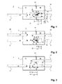
- FIG. 1 a first embodiment of a silencer according to the invention is shown.
- the silencer 1 has a gas-tight housing 2 made of stainless steel, in the interior of which a first volume 41 and a second volume 42 separated from the first volume by the partition wall 31 are defined by means of a partition wall 31 made of stainless steel.
- a stainless steel inlet pipe 51 penetrates a wall of the housing 2 and opens up (ie, with an enlarged cross section) in the first volume 41.
- a first outlet pipe 61 and a second outlet pipe 7 penetrate both a wall of the housing 2 and the partition wall 31 and thereby enforce the second volume 42.
- Aufgetulpte estuaries of the first outlet tube 61 and the second outlet tube 7 are arranged in the first volume.
- the first outlet pipe 61 and the second outlet pipe 7 are formed of stainless steel.
- the first outlet pipe 61 passes through the second volume 42 and the partition wall 31 in a straight line and is free from openings in the interior of the housing 2 on its wall (with the exception of the orifice arranged in the first volume). Further, the outer walls of the first outlet pipe 61 and the resonator tube 8 are connected to the partition wall 31 by spot welding (and thus not gas-tight), and the inlet pipe 51 is aligned with the second outlet pipe 7 and the resonator pipe 8.
- a flap 10 is arranged in stainless steel inside the second outlet 7, which can be selectively brought by means of an electric motor 11 in a position in which the flap 10 and the second outlet tube 7 closes and thus deactivated, and in a position can be brought, in which the flap 10, the second outlet tube 7 does not close and activated.
- the electric motor 11 is connected via a control line to a motor controller 16, which operates the electric motor 11 in response to a speed and / or load of an internal combustion engine (not shown).
- the electric motor may alternatively be provided a hydraulic or pneumatic, which forcibly actuates the flap 10.
- a resonator tube 8 made of stainless steel which passes through the partition wall 31 and the second outlet tube 7 in the portion in which it passes through the at least one partition wall 31, completely surrounds with a radial distance in the circumferential direction.
- the second outlet tube 7 in the portion in which it passes through the partition wall 31, inside the rectilinearly extending resonator tube 8 is arranged.
- the second outlet tube 7 passes through the resonator tube 8 over its entire longitudinal extent and still projects beyond the resonator tube 8 into the interior of the first volume 41.
- the first outlet pipe 61 and the second outlet pipe 7 have a cross-section which changes over their longitudinal extent and in particular in the region of the mouth.
- the cross section of the inlet pipe 51 also changes along its longitudinal extension and is enlarged in the area of the orifice, whereas the resonator pipe 8 has a cross section which is constant over its longitudinal extent.
- the resonator tube 8 provides a fluid connection between the first volume 41 and the second volume 42 via an annular gap formed between an outer wall of the second outlet tube 7 and an inner wall of the resonator tube 8.
- the second outlet tube 7 has in its wall openings 91, which are arranged with respect to the dividing wall 31 partly on sides of the first volume 41 and partly on sides of the second volume 42.
- the resonator tube 8 is free of openings over its entire extent (with the exception of the mouths of the resonator tube).
- the second outlet tube 7 also provides fluid communication between the first volume 41 and the second volume 42.
- the partition 31 is, with the exception of the openings in which it is penetrated by pipes, over its entire extent also free of openings.
- the second volume 42 thus forms a Helmholz volume, the annular gap of the resonator tube 8 a first Helmholzrohr, the second outlet tube 7 via the openings 91 and the annular gap a second Helmholzrohr, and the Helmholzrohre and the Helmholz volume together a Helmholtz resonator.
- the volume of air columns standing between the unfinished first volume 41 and the closed second volume 42 (Helmholz volume) is decisive.
- the volumes of the standing air columns depend on the length and cross section of the respective Helmholzrohres.
- the length L1, L1 ', L2 of the respective effective Helmholzrohres depends on whether the flap 10 is open or closed and thus the second outlet tube 7 is active or inactive.
- the effective length L2 of the first Helmholz tube is limited to a portion of the annular gap formed between the outer wall of the second outlet tube 7 and the inner wall of the resonator tube 8.
- This section of the annular gap starts at the mouth of the resonator tube 8 arranged in the interior of the second volume 42 and extends in the longitudinal direction of the resonator tube 8 to the point at which the second outlet tube 7 has the openings 91.
- the second Helmholz tube is not active when the flap 10 is open and thus has no effective length, since in the interior of the second outlet tube 7 no standing column of air forms. As a result, the Helmholtz resonator with open flap 10 only a natural frequency.
- the effective length L1 of the first Helmholzrohres extends over the whole Length of the annular gap formed between the outer wall of the second outlet tube 7 and the inner wall of the resonator 8 and thus over the entire length of the resonator 8.
- the second Helmholz tube has an effective length L1 'with the flap closed, at the inside of the second volume 42nd arranged mouth of the resonator tube 8 begins and initially extends along the annular gap to the point at which the second outlet tube 7 has the openings 91.
- the effective length L1 'of the second Helmholzrohres extends through the openings 91 through to the arranged in the interior of the first volume 41 mouth of the second outlet tube 7.
- the cross section of the standing column of air of the second Helmholzrohres over the length L1' changes since, starting from the second volume 42, initially only the annular gap formed between the outer wall of the second outlet tube 7 and the inner wall of the resonator tube 8 contributes to the stationary air column of the second Helmholz tube, but in the further course the entire inner diameter of the second outlet tube 7 contributes to the stationary air column of the second Helmholz tube , As a result, the Helmholtz resonator with closed flap 10 at least two different natural frequencies.
- the effective length L2 of the first Helmholzrohres with open flap 10 is also smaller than the effective lengths L1, L1 'of the first and second Helmholzrohres with the flap 10 and thus deactivated second outlet tube 7.
- the natural frequencies change from the second volume 42 and the first and second Helmholz tubes formed Helmholtz resonator in response to an operating state of the second outlet pipe. 7
- FIG. 2 a second embodiment of the muffler according to the invention described.
- FIG. 2 a second embodiment of the muffler according to the invention described.
- particular attention is paid to differences from the first embodiment described above and otherwise referred to the above first embodiment.
- the second embodiment differs from the first embodiment described above in that not only an inlet tube 51 but also a second inlet tube 52 is provided, which second inlet tube 52 as well as the first inlet tube 51 a wall of the housing. 2 penetrates and opens in the first volume 41.
- both inlet tubes 51, 52 and all outlet tubes 61, 7 have a constant cross-section at least in the interior of the housing 2 and are therefore not shaped in the area of their mouths.
- the flap 10 is biased in the second embodiment by a spring in a closed position and thus a passive component which automatically opens at a corresponding pressurization and the second outlet tube 7 thus automatically activated or deactivated.
- the resonator tube 8 is gas-tightly connected to the second outlet tube 7 at its mouth disposed in the interior of the first volume 41 via a weld 13, and the annular gap between the second outlet tube 7 and the resonator tube 8 is thus closed at this point.
- the fluid connection between the first volume 41 and the second volume 42 and thus the Helmholz tube of the Helmholtz resonator is therefore in this embodiment in sections over the annular gap between the resonator 8 and the second outlet tube 7 and partially via the openings 91 over a portion of the second outlet tube 7 provided.
- the Helmholz tube When the flap 10 is closed, the Helmholz tube has an effective length L1 which starts at the mouth of the resonator tube 8 arranged in the interior of the second volume 42 and initially extends along the annular gap to the point at which the second outlet tube 7 has the openings 91 , About that In addition, with the flap 10 closed, the effective length L1 of the Helmholz tube extends through the openings 91 to the mouth of the second outlet tube 7 arranged in the interior of the first volume 41.
- the two inlet pipes 51, 52, the first outlet pipe 61, and the second outlet pipe 62 in the interior of the housing are straight.
- FIG. 3 a third embodiment of the silencer according to the invention described.
- differences to the first or second embodiment are essentially discussed, and otherwise reference is made to the above embodiments.
- the muffler 1 according to the third embodiment differs from the muffler 1 according to the first embodiment particularly in that, as in the second embodiment, a passive flap 10 is used, but unlike the above-described first and second embodiments, it is not outside the housing 2 but within the housing 2 in the interior of the second outlet pipe 7 is arranged.
- the flow direction of the exhaust gas is reversed so that the first and second exhaust pipes 7, 61 are in fluid communication with an internal combustion engine, and the inlet pipe 51 is in fluid communication with an exhaust system exhaust pipe.
- the resonator tube 8 does not have a constant cross-section over the entire longitudinal extent, but is erected in the region of its mouths and has an enlarged cross-section there.
- the resonator tube 8 is supported by the second outlet tube 7 via a plurality of radial pillars 14 distributed in the circumferential direction of the second outlet tube 7.
- the second outlet tube 7 does not completely penetrate the resonator tube 8 in the longitudinal direction thereof, so that a mouth of the second outlet tube 7 is arranged inside the resonator tube 8 and the resonator tube 8 extends beyond the second outlet tube 7 into the second outlet tube 7 Interior of the first volume 41 protrudes.
- a wall of the second outlet tube 7 as well as the wall of the resonator tube has no openings.
- the effective length L2 of the Helmholz tube is limited to the length of the annular gap formed between the outer wall of the second outlet tube 7 and the inner wall of the resonator tube 8.
- This annular gap extends between the mouth of the resonator tube 8 arranged in the interior of the second volume 42 up to the mouth of the second outlet tube 7 arranged in the interior of the resonator tube 8.
- the Helmholz tube When the flap 10 is closed, the Helmholz tube has an effective length L1, which begins at the mouth of the resonator tube 8 arranged in the interior of the second volume 42 and initially extends along the annular gap to the mouth of the second outlet tube 7 arranged in the interior of the resonator tube 8.
- the effective length L1 of the Helmholz tube extends with the flap 10 closed to the mouth of the resonator tube 8 arranged in the interior of the first volume 41. Both the cross section of the annular gap and the cross section of the resonator tube 8 change due to the bulging of the resonator tube 8 the length of the resonator tube. 8
- the Helmholtz tube of the Helmholtz resonator thus formed has two different lengths L1 and L2 and different cross sections and thus the Helmholtz resonator thus formed between two different natural frequencies can be tuned.
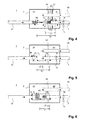
- FIG. 4 a fourth embodiment of the silencer according to the invention described.
- differences are essentially made to the above-described first to third embodiments and otherwise referred to the above statements.
- FIG. 4 shown fourth embodiment differs from the embodiments described above, in particular by the fact that a further partition 32 is provided made of stainless steel, which defines in the interior of the housing 2 between the first volume 41 and the second volume 42 arranged third volume 43, which is filled with insulating material is.
- the first outlet pipe 61 and the second outlet pipe 7 do not only penetrate gas-tight, the wall of the housing 2 but also in a sliding fit, the first partition wall 31 and the second partition wall 32.
- the resonator 8, which is arranged in the interior of the housing 42 mouth may be arranged in the interior of the housing 42 mouth as enlarged cross-section, interspersed both first partition wall 31 and the second partition 32 in a sliding fit.
- the inlet pipe 51 and the outlet pipe 7 are integrally formed in the illustrated embodiment.
- a wall of the one-piece tube thus formed has, within the first volume 41 in a section in which the tube is not surrounded by the resonator tube 8, openings 92 which allow a passage of fluid guided in the inlet tube 51 into the first volume 41.
- the tube formed integrally from the inlet tube 51 and the second outlet tube 7 also has openings 91 in a section in which it is arranged inside the resonator tube 8. Between the openings 91 and 92, the pipe formed integrally from the inlet pipe 51 and the second outlet pipe 7 has a section of changed, here reduced diameter, which acts as a throttle.
- the effective length L2 of the Helmholz tube limited as in the first and second embodiment along the annular gap formed between the outer wall of the second outlet tube 7 and the inner wall of the Resonatorrohres 8 on a portion between the inside second orifice 42 of the resonator tube 8 and the point at which the tube formed integrally from the inlet tube 51 and the second outlet tube 7 has the openings 91.
- the effective length L 1 of a first Helmholz tube extends over the entire length of the tube formed integrally between the outer wall of the tube formed from the inlet tube 51 and the second outlet tube 7
- a second Helmholzrohr an effective length L1 ', which starts at the arranged in the interior of the second volume 42 mouth of the resonator tube 8 and initially extends along the annular gap to the point at which the tube formed integrally from the inlet tube 51 and the second outlet tube 7 has the openings 91.
- the effective length L1 of the Helmholtz tube extends through the apertures 91 inside the tube formed integrally from the inlet tube 51 and the second outlet tube 7 to the point at which the inlet tube 51 and the second outlet tube 7 integrally formed tube having the openings 92.
- the volumes of the standing air columns of the Helmholtz resonator thus formed vary depending on whether the flap 10 disposed inside the second outlet tube 7 is open or closed so that the natural frequencies of the Helmholtz resonator can be switched.
- FIG. 5 a fifth embodiment of a muffler according to the invention described, reference being made to avoid repetition of the statements to the above first to fourth embodiments, and in particular the differences will be discussed.
- the fifth embodiment differs from the above third embodiment in particular in that a mouth of the inlet tube 51 is disposed inside the resonator tube 8 and the resonator tube 8 is also supported on the inlet tube 51 via radial supports 15 distributed circumferentially of the inlet tube 51.
- the mouths of the resonator tube 8 are notamitulpt, so that the resonator tube 8 has a constant cross section over its entire longitudinal extent.
- the fluid supplied to the first volume 41 in this embodiment in the inlet pipe 51, and in particular exhaust gas is supplied through an annular gap between the resonator pipe 8 and the inlet pipe 51.
- the effective length L2 of the Helmholz tube is limited to the length of the annular gap formed between the outer wall of the second outlet tube 7 and the inner wall of the resonator tube 8.
- This annular gap extends between the mouth of the resonator tube 8 arranged in the interior of the second volume 42 up to the mouth of the second outlet tube 7 arranged in the interior of the resonator tube 8.
- the Helmholz tube When the flap 10 is closed, the Helmholz tube has an effective length L1, which begins at the mouth of the resonator tube 8 arranged in the interior of the second volume 42 and initially extends along the annular gap to the mouth of the second outlet tube 7 arranged in the interior of the resonator tube 8.
- the effective length L1 of the Helmholz tube extends with the flap 10 closed to a point in front of the mouth of the inlet tube 51 arranged inside the resonator tube 8.
- the volume of the standing air column of the Helmholtz resonator formed of Helmholz tube and second volume 42 can be adjusted, so that the Helmholtz resonator has two switchable natural frequencies having.
- FIG. 6 a sixth embodiment of a silencer according to the invention described.
- particular reference is made to differences from the fifth embodiment described above, and otherwise to the above embodiments.
- the muffler 1 according to the sixth embodiment differs from the fifth embodiment described above particularly in that the annular gap between the resonator tube 8 and the inlet tube 51 is closed by a weld 13.
- a weld 13 may also be provided a ring aperture.
- the resonator tube 8 in a section, in which is not penetrated by the second outlet pipe 7, openings 93, via which in the inlet pipe 51 guided fluid in the first volume 41 can be supplied.
- the second outlet pipe 7 has in the in FIG. 6 shown embodiment in its wall openings 91.
- the Helmholz tube When the flap 10 is closed, the Helmholz tube has an effective length L1, which begins at the mouth of the resonator tube 8 arranged in the interior of the second volume 42 and initially extends along the annular gap to the mouth of the second outlet tube 7 arranged in the interior of the resonator tube 8. In the area of the openings 91, in addition to the annular gap, the cross section of the second outlet pipe contributes to the air column standing in the Helmholz tube. In addition, the effective length L1 of the Helmholz tube with the flap 10 closed extends inside the resonator tube 8 as far as the openings 93 of the resonator tube 8.
- the effective length L1, L2 and the effective cross section of the Helmholz tube 8 of the Helmholtz resonator thus formed changes and is between (at least) two natural frequencies switchable.
- FIG. 7 a seventh embodiment of a silencer according to the invention described.
- particular reference is made to differences from the sixth embodiment described above, and otherwise to the preceding statements.
- the muffler 1 has a resonator tube 8 formed integrally with the inlet pipe 51, which forms the wall of the resonator tube 8 Housing 2 and the partition wall 31 passes through and opens into the second volume 42.
- the resonator tube 8 formed integrally with the inlet pipe 51 has openings 93 which allow a passage of fluid guided in the inlet pipe 51 and, in particular, exhaust gas into the first volume 41 enable.
- a wall of the resonator tube 8 formed integrally with the inlet pipe 51 is free from exhaust ports.
- first outlet pipes 61 and 62 are provided, of which a first outlet pipe downstream of the flap 10 arranged in the second outlet pipe 7 is connected via a connecting piece to the second outlet pipe 7 to a single common outlet pipe.
- all the outlet pipes downstream of the valve disposed in the second outlet 7 flap 10 may be interconnected.
- the Helmholz tube When the flap 10 is open, the Helmholz tube has an effective length L2 which begins at the mouth of the resonator tube 8 arranged in the interior of the second volume 42 and extends over the annular gap (between the resonator tube 8 formed integrally with the inlet tube 51 and the second outlet tube 7). extends to the arranged in the interior of the resonator 8 opening of the second outlet pipe 7.
- L2 effective length
- the Helmholz tube When the flap 10 is closed, the Helmholz tube has an effective length L1 which starts at the mouth of the resonator tube 8 arranged in the interior of the second volume 42 and initially along the annular gap (between the resonator tube 8 formed integrally with the inlet tube 51 and the second outlet tube 7 ) extends to the arranged in the interior of the resonator 8 opening of the second outlet pipe 7.
- the effective length L 1 of the Helmholz tube with the flap 10 closed extends inside the resonator tube 8 as far as the openings 93 of the resonator tube 8.
- the flap 10 is open or closed, is an effective length and an effective cross-section, and thus a volume of between the open first volume 41 and the closed second volume 42 standing air column of the Helmholtz resonator thus formed switchable, so that also changes the respective natural frequency of the Helmholtz resonator.
- the connecting piece between the outlet pipes is arranged outside the housing 2, it is emphasized that this can also be arranged within the housing 2.
- FIG. 8 an embodiment of an exhaust system is described, which uses a silencer according to the invention according to one of the preceding embodiments.
- exhaust gas is supplied via a catalytic converter 18 and via the inlet pipe 51 to a housing 2 of a silencer 1 designed as described above.
- the first outlet pipe 61 and the second outlet pipe 7 are brought together by means of a Y-piece, before the exhaust gas is discharged via a tail pipe becomes.
- the electric motor 11 which actuates the flap 10, in the embodiment shown by a motor controller 19 in response to a respective speed of the engine 17th
- a muffler 1 according to an eighth embodiment described.
- This muffler 1 largely corresponds to the muffler in FIG. 1 shown first embodiment. Therefore, in order to avoid repetition, particular reference is made to differences from the first embodiment described above and otherwise referred to the comments on the first embodiment.
- the muffler 1 according to the eighth embodiment differs from the muffler according to the first embodiment in that the inlet pipe 51, the first outlet pipe 61 and the second outlet pipe 7 have a constant cross section throughout; Thus, on the in FIG. 1 omitted revolutions in the estuaries.
- a second partition wall 32 is provided in the housing 2 parallel to the partition wall 31. Both Partitions 31 and 32 are penetrated by the resonator tube 8. The use of two mutually spaced apart partitions 31, 32 facilitates support and thus secure storage of the resonator tube 8 in the interior of the housing. 2
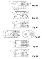
- FIG. 9B a muffler 1 according to a ninth embodiment described.
- This muffler largely corresponds to the muffler in FIG. 3 shown third embodiment. Therefore, in order to avoid repetition, particular reference is made to differences from the third embodiment described above and otherwise refer to the comments on the third embodiment.
- the muffler 1 according to the ninth embodiment differs from the muffler according to the third embodiment in that the resonator tube 8 has a constant cross section throughout; Thus, on the in FIG. 3 shown bulge of the resonator tube 8 omitted in the mouths. Further, in the ninth embodiment, the resonator tube 8 is not supported by the second outlet tube 7 via a plurality of radial pillars 14 distributed in the circumferential direction of the second outlet tube 7; Rather, the annular gap formed between the resonator tube 8 and the second outlet tube 7 is free of supports. Finally, in a section in which it is arranged in the interior of the resonator tube 8, the second outlet tube 7 has openings 91. As in the above eighth embodiment, a second partition wall 32 is provided in the housing 2 parallel to the partition wall 31, and both partition walls 31 and 32 are penetrated by the resonator pipe 8.
- FIG. 9C a muffler 1 according to a tenth embodiment described.
- This muffler corresponds to a transitional shape between the eighth embodiment described above and the ninth embodiment described above. Therefore, to avoid repetition, particular attention is paid to differences from the above-described eighth and ninth embodiments, and otherwise refer to the comments on the eighth and ninth embodiments.
- the muffler 1 according to the tenth embodiment differs from the muffler according to the eighth embodiment in that the second exhaust pipe 7 does not protrude beyond the resonator pipe 8 into the first volume 41; Rather, the mouths of the second outlet tube 7 and the resonator tube 8 are aligned with each other. Accordingly, unlike in the ninth embodiment, the mouth of the second outlet tube 7 is arranged only in the radial direction and not also in the axial direction of the resonator tube 8 in the interior of the resonator tube 8.
- FIG. 9D a muffler 1 according to an eleventh embodiment described.
- This muffler 1 largely corresponds to the muffler in FIG. 2 shown second embodiment. Therefore, in order to avoid repetition, particular reference is made to differences from the second embodiment described above and otherwise refer to the comments on the second embodiment.
- the muffler 1 according to the eleventh embodiment differs from the muffler according to the second embodiment in that the annular gap between the second outlet pipe 7 and the resonator tube 8 is not sealed gas-tight by a weld but by an annular shutter 13. Further, only one inlet pipe 51 is provided, so that the second inlet pipe 52 has been omitted.
- a second partition 32 is provided in the housing 2 to the partition wall 31 spaced parallel and both partitions 31 and 32 of the resonator tube 8 (and thus also arranged in the resonator tube 8 second outlet pipe 7).
- the use of a ring diaphragm 13 permits reciprocal support of the resonator tube 8 and the second outlet tube 7.
- the muffler 1 according to the in Figure 9E differs from the muffler according to the eleventh embodiment in that the second outlet pipe 7 does not protrude beyond the resonator tube 8 into the first volume 41; Rather, the resonator tube 8 projects beyond an opening of the second outlet tube 7 into the first volume 41. Accordingly, an opening of the second outlet tube is arranged both in the radial direction and in the axial direction of the resonator tube 8 in the interior of the resonator tube 8 and spaced from an opening of the resonator tube 8.
- the muffler 1 according to the in FIG. 9F Thirteenth embodiment shown differs from the muffler according to the in FIG. 9D 11 shown eleventh embodiment in that the second outlet tube 7 does not protrude beyond the resonator 8 out into the first volume 41; Rather, the mouths of the second outlet tube 7 and the resonator tube 8 are aligned with each other.
- FIG. 9G a muffler 1 according to a fourteenth embodiment described.
- This muffler largely corresponds to the muffler in FIG. 9C shown tenth embodiment. Therefore, to avoid repetition, particular attention will be paid to differences from the tenth embodiment described above and otherwise referred to the comments on the tenth embodiment.
- the muffler 1 according to the fourteenth embodiment differs from the muffler of the tenth embodiment particularly in the arrangement of the inlet pipe 51 and the first outlet pipe 61.
- the first outlet pipe 61 does not penetrate the partition walls 31 and 32; Rather, the first outlet pipe 61 and the second outlet pipe 7 leave the housing 2 on opposite sides of the housing 2.
- the inlet pipe 51 is arranged so as to be flush with none of the exhaust pipes 61, 7; Rather, it is opposite to the outlet pipes 61, 7 arranged rotated by 90 °.
- the arrangement of the tubes in the fourteenth embodiment is merely exemplary and is intended to show that the at least one inlet tube and the outlet tubes can be arranged almost arbitrarily relative to each other, as long as all in the first Volume 41 open and the second outlet pipe 7 is at least partially surrounded by the resonator tube 8, which is arranged between the first volume 41 and the second volume 42. It is further emphasized that the use of several partitions is only optional; Alternatively, more than two or only one partition can be used. Furthermore, the at least one inlet tube and the outlet tubes as well as the at least one resonator tube can have a constant cross section over their entire longitudinal extent, or alternatively have an enlarged cross section, for example in the region of their mouths, and thus be sculpted.
- FIG. 9H a muffler 1 according to a fifteenth embodiment described.
- This muffler largely corresponds to the muffler in FIG. 9B shown ninth embodiment. Therefore, to avoid repetition, particular attention is paid to differences from the above-described ninth embodiment and otherwise refer to the comments on the ninth embodiment.
- the muffler 1 according to the fifteenth embodiment differs from the muffler of the ninth embodiment in that the mouths of the first outlet pipe 61 and the resonator pipe 8 are aligned with the partition wall 31.
- the first outlet pipe 61 and the resonator tube 8 do not protrude beyond the partition wall 31 into the first volume 41.
- the mouth of the second outlet tube 7 is set back relative to the mouth of the resonator tube 8, so that the second outlet tube 7 does not penetrate the dividing wall 31.
- FIG. 9I a muffler 1 according to a sixteenth embodiment described.
- This muffler largely corresponds to the muffler in FIG. 9C shown tenth embodiment. Therefore, to avoid repetition, particular attention will be paid to differences from the tenth embodiment described above and otherwise referred to the comments on the tenth embodiment.
- the muffler 1 according to the sixteenth embodiment differs of the muffler of the tenth embodiment in that the mouths of the first outlet pipe 61 and the second outlet pipe 7 and the resonator tube 8 are aligned with the partition wall 31.
- the first outlet pipe 61 and the second outlet pipe 7 as well as the resonator pipe 8 do not protrude beyond the partition wall 31 into the first volume 41.
- the muffler 1 according to the seventeenth embodiment differs from the muffler of the eighth embodiment in that the mouth of the resonator tube 8 is aligned with the partition wall 31.
- the mouth of the resonator tube 8 is aligned with the partition wall 31.
- FIG. 9K a muffler 1 according to an eighteenth embodiment described.
- This muffler largely corresponds to the muffler in FIG. 9I shown sixteenth embodiment. Therefore, to avoid repetition, particular attention will be paid to differences from the above-described sixteenth embodiment, and otherwise refer to the comments on the sixteenth embodiment.
- FIG. 9K shows the left drawing greatly simplified schematically a schematic diagram of the muffler 1 according to the eighteenth embodiment and the right drawing a plan view of the partition wall 31 in the direction X, wherein the partition wall 31 is rotated with respect to the left drawing by 90 ° counterclockwise.
- the muffler 1 according to the eighteenth embodiment differs from the muffler of the sixteenth embodiment in that Annular gap between the resonator tube 8 and the second outlet tube 7 supports 14 are arranged. These supports are formed by the partition wall 31 in that in the region of the partition wall 31, in which the partition closes the annular gap formed between the resonator tube 8 and the second outlet tube 7, a plurality of circularly arranged openings are provided. Between these openings remain the supports 14. In this way, a largely open annular gap is obtained, while ensuring that the second outlet pipe 7 is supported by the partition wall 31.
- the manner of supporting the second outlet tube shown in the eighteenth embodiment is only exemplary.
- the support can also take place, for example, by bolts arranged between the resonator tube and the second outlet tube or between the dividing wall and the second outlet tube, or by tabs formed on one of the dividing walls or the bypass tube, or by indentations or projections formed on the resonator tube or the second outlet tube.
- FIG. 9L a muffler according to a nineteenth embodiment described.
- This muffler largely corresponds to the muffler in FIG. 9D shown eleventh embodiment. Therefore, to avoid repetition, particular attention is paid to differences from the eleventh embodiment described above, and otherwise refer to the comments on the eleventh embodiment.
- the muffler according to the nineteenth embodiment differs from the muffler of the eleventh embodiment particularly in that the mouth of the resonator tube 8 is aligned with the partition wall 31.
- the mouth of the resonator tube 8 is aligned with the partition wall 31.
- the annular gap formed between the resonator tube 8 and the second outlet tube 7 is not closed by a separate annular aperture but by the partition wall 31 itself. This also allows a direct support of both first and second outlet pipe 61, 7 and resonator 8 through the partition wall 31st
- the silencer according to the twentieth embodiment differs from the silencer of the thirteenth embodiment particularly in that the mouths of the first outlet pipe 61, the second outlet pipe 7 and the resonator pipe 8 are aligned with the partition wall 31.
- the first outlet pipe 61 nor the second outlet pipe 7 nor the resonator tube 8 protrude beyond the partition wall 31 into the first volume 41.
- the annular gap formed between the resonator tube 8 and the second outlet tube 7 is not closed by a separate annular aperture, but by the partition wall 31 itself.
- Helmholtz tube has heretofore been used to designate the area in which a standing column of air is formed between the open first volume and the closed second volume, this term is functional rather than restrictive (e.g. physical pipe). Accordingly, the Helmholzrohr can have any and also over the course of the Helmholzrohres changing cross-section.
- annular gap as used above is not restricted to columns with a circular cross-section but should also include columns with an oval or rectangular cross-section. Further, the columns may be continuous in the circumferential direction, but may alternatively be interrupted in the circumferential direction.
Landscapes
- Engineering & Computer Science (AREA)
- Chemical & Material Sciences (AREA)
- Combustion & Propulsion (AREA)
- Mechanical Engineering (AREA)
- General Engineering & Computer Science (AREA)
- Exhaust Silencers (AREA)
Applications Claiming Priority (1)
| Application Number | Priority Date | Filing Date | Title |
|---|---|---|---|
| DE102014107907.8A DE102014107907A1 (de) | 2014-06-04 | 2014-06-04 | Schalldämpfer |
Publications (3)
| Publication Number | Publication Date |
|---|---|
| EP2955344A2 true EP2955344A2 (fr) | 2015-12-16 |
| EP2955344A3 EP2955344A3 (fr) | 2016-02-17 |
| EP2955344B1 EP2955344B1 (fr) | 2016-12-07 |
Family
ID=53264545
Family Applications (1)
| Application Number | Title | Priority Date | Filing Date |
|---|---|---|---|
| EP15169284.5A Active EP2955344B1 (fr) | 2014-06-04 | 2015-05-26 | Silencieux |
Country Status (5)
| Country | Link |
|---|---|
| US (2) | US9429052B2 (fr) |
| EP (1) | EP2955344B1 (fr) |
| JP (1) | JP6063002B2 (fr) |
| CN (1) | CN105156176B (fr) |
| DE (1) | DE102014107907A1 (fr) |
Cited By (2)
| Publication number | Priority date | Publication date | Assignee | Title |
|---|---|---|---|---|
| EP3514342A1 (fr) * | 2018-01-22 | 2019-07-24 | Eberspächer Exhaust Technology GmbH & Co. KG | Amortisseur de bruit |
| US11377989B2 (en) | 2018-01-22 | 2022-07-05 | Purem GmbH | Muffler |
Families Citing this family (24)
| Publication number | Priority date | Publication date | Assignee | Title |
|---|---|---|---|---|
| DE102014103054A1 (de) | 2014-03-07 | 2015-09-10 | Tenneco Gmbh | Abgasschalldämpfer |
| DE102014107907A1 (de) * | 2014-06-04 | 2015-12-17 | Eberspächer Exhaust Technology GmbH & Co. KG | Schalldämpfer |
| DE102015222088B4 (de) * | 2015-11-10 | 2025-09-04 | Purem GmbH | Schalldämpfer für eine Abgasanlage |
| CN105569775B (zh) * | 2016-03-07 | 2018-06-19 | 广州汽车集团股份有限公司 | 排气消声器及具有其的车辆 |
| US10180093B2 (en) * | 2016-04-13 | 2019-01-15 | GM Global Technology Operations LLC | Selectively tunable exhaust noise attenuation device |
| US11371401B2 (en) * | 2017-03-27 | 2022-06-28 | Honda Motor Co., Ltd. | Exhaust muffler |
| US11365658B2 (en) | 2017-10-05 | 2022-06-21 | Tenneco Automotive Operating Company Inc. | Acoustically tuned muffler |
| DE102018124198A1 (de) | 2017-10-05 | 2019-04-11 | Tenneco Automotive Operating Company Inc. | Akustisch abgestimmter Schalldämpfer |
| US11199116B2 (en) | 2017-12-13 | 2021-12-14 | Tenneco Automotive Operating Company Inc. | Acoustically tuned muffler |
| CN110030060B (zh) * | 2017-12-27 | 2021-06-01 | 本田技研工业株式会社 | 用于车辆的排气消声器结构 |
| US10900396B2 (en) * | 2018-01-15 | 2021-01-26 | Ford Global Technologies, Llc | Exhaust orifice tube for vehicle mufflers |
| US11293664B2 (en) * | 2018-03-06 | 2022-04-05 | Gulfstream Aerospace Corporation | Dual tube silencer for separate gas flows |
| EP3557015B1 (fr) * | 2018-04-20 | 2020-11-04 | Volvo Car Corporation | Silencieux comprenant un résonateur de type helmholtz et véhicule avec ce silencieux |
| DE102018112963A1 (de) * | 2018-05-30 | 2019-12-05 | Faurecia Emissions Control Technologies, Germany Gmbh | Schalldämpfer für eine Abgasanlage einer Brennkraftmaschine |
| US11268429B2 (en) | 2019-01-17 | 2022-03-08 | Tenneco Automotive Operating Company Inc. | Diffusion surface alloyed metal exhaust component with inwardly turned edges |
| US11268430B2 (en) | 2019-01-17 | 2022-03-08 | Tenneco Automotive Operating Company Inc. | Diffusion surface alloyed metal exhaust component with welded edges |
| JP6936262B2 (ja) * | 2019-01-28 | 2021-09-15 | フタバ産業株式会社 | 消音器 |
| US11391195B2 (en) * | 2019-06-19 | 2022-07-19 | Tenneco Automotive Operating Company Inc. | Exhaust system and muffler |
| US11441456B2 (en) * | 2019-07-01 | 2022-09-13 | Toyota Motor North America, Inc. | Tuning a sound profile of a muffler |
| US11421569B2 (en) | 2019-10-18 | 2022-08-23 | Tenneco Automotive Operating Company Inc. | Muffler |
| US12071874B2 (en) * | 2020-01-24 | 2024-08-27 | K&N Engineering, Inc. | Sound attenuating engine exhaust system |
| US10975743B1 (en) | 2020-03-13 | 2021-04-13 | Tenneco Automotive Operating Company Inc. | Vehicle exhaust component |
| CN112523838B (zh) * | 2020-12-01 | 2022-08-05 | 潍柴动力股份有限公司 | 车辆排气降噪方法、装置、后消声装置及消声器 |
| US11802499B2 (en) * | 2021-11-23 | 2023-10-31 | Tenneco Automotive Operating Company Inc. | Exhaust system tuner tube to reduce standing wave |
Citations (6)
| Publication number | Priority date | Publication date | Assignee | Title |
|---|---|---|---|---|
| US2112964A (en) | 1936-12-28 | 1938-04-05 | Buffalo Pressed Steel Company | Muffler |
| US3613830A (en) | 1969-07-18 | 1971-10-19 | Walker Mfg Co | One-piece tube and shell assembly for silencer |
| US4501341A (en) | 1981-03-12 | 1985-02-26 | Jones Adrian D | Low frequency muffler |
| US5602368A (en) | 1993-12-24 | 1997-02-11 | Apex Co., Ltd. | Muffler for an internal combustion engine |
| DE102008062014A1 (de) | 2008-12-12 | 2010-06-17 | Friedrich Boysen Gmbh & Co. Kg | Schalldämpfer |
| EP1760279B1 (fr) | 2005-09-01 | 2010-10-13 | J. Eberspächer GmbH & Co. KG | Silencieux pour un système d'échappement |
Family Cites Families (35)
| Publication number | Priority date | Publication date | Assignee | Title |
|---|---|---|---|---|
| US2834427A (en) * | 1953-12-22 | 1958-05-13 | Walker Mfg Company Of Wisconsi | Muffler having a cover and a retaining strip therefor |
| US2985252A (en) * | 1955-01-20 | 1961-05-23 | Gen Motors Corp | Exhaust muffler |
| US3070187A (en) * | 1959-05-18 | 1962-12-25 | Oldberg Mfg Company | Sound-attenuating system and apparatus for gas streams |
| JPS548233A (en) * | 1977-06-22 | 1979-01-22 | Toyota Motor Corp | Exhaust pipe |
| JPS54143941U (fr) * | 1978-03-30 | 1979-10-05 | ||
| JPS61126016U (fr) * | 1985-01-28 | 1986-08-07 | ||
| JPS6290915U (fr) * | 1985-11-28 | 1987-06-10 | ||
| JPH0833105B2 (ja) * | 1986-12-26 | 1996-03-29 | ヤマハ発動機株式会社 | 内燃機関の排気装置 |
| JPH068267Y2 (ja) * | 1987-01-28 | 1994-03-02 | カルソニック株式会社 | 制御型消音器の尾管構造 |
| JPH0213124U (fr) * | 1988-07-04 | 1990-01-26 | ||
| US5614699A (en) * | 1994-05-09 | 1997-03-25 | Nissan Motor Co., Ltd. | Automobile exhaust noise suppressor |
| JP3443187B2 (ja) * | 1994-11-04 | 2003-09-02 | カルソニックカンセイ株式会社 | 制御型排気系システム |
| JP3379254B2 (ja) * | 1994-12-26 | 2003-02-24 | 日産自動車株式会社 | 排気消音装置 |
| US5712454A (en) * | 1995-01-27 | 1998-01-27 | Honda Giken Kogyo Kabushiki Kaisha | Exhaust system in internal combustion engine |
| EP0733785B1 (fr) * | 1995-02-24 | 2003-07-16 | Calsonic Kansei Corporation | Contrôleur d'un silencieux utilisable dans un système contrôlable des gaz d'échappement d'un moteur à combustion interne |
| JP3511779B2 (ja) * | 1996-01-31 | 2004-03-29 | 日産自動車株式会社 | エンジンの排気消音装置 |
| JP3214338B2 (ja) * | 1996-03-06 | 2001-10-02 | 日産自動車株式会社 | 自動車用排気消音装置 |
| DE19729666C2 (de) * | 1996-07-20 | 2002-01-17 | Gillet Heinrich Gmbh | Schalldämpfer mit variabler Dämpfungscharakteristik |
| US5984045A (en) * | 1997-02-14 | 1999-11-16 | Nissan Motor Co., Ltd. | Engine exhaust noise suppressor |
| JP3342461B2 (ja) * | 2000-03-01 | 2002-11-11 | 本田技研工業株式会社 | 排気消音装置 |
| DE10034557A1 (de) * | 2000-07-15 | 2002-01-24 | Eberspaecher J Gmbh & Co | Ventil in einer abgas-Schalldämpfer-Anlage eines Kraftfahrzeugs |
| DE10300773A1 (de) * | 2003-01-11 | 2004-07-22 | Daimlerchrysler Ag | Abgasanlage für eine mehrzylindrige Brennkraftmaschine |
| US20070125594A1 (en) * | 2005-12-01 | 2007-06-07 | Hill William E | Muffler assembly with sound absorbing member |
| CN2871858Y (zh) * | 2006-02-28 | 2007-02-21 | 重庆长安汽车股份有限公司 | 一种机动车用消声器 |
| US7337609B2 (en) * | 2006-05-11 | 2008-03-04 | Gm Global Technology Operations, Inc. | Diesel exhaust system variable backpressure muffler |
| JP2008045495A (ja) * | 2006-08-17 | 2008-02-28 | Honda Motor Co Ltd | 排気消音装置 |
| US8468813B2 (en) * | 2007-03-16 | 2013-06-25 | Tenneco Automotive Operating Company Inc. | Snap-action valve for exhaust system |
| WO2008150024A1 (fr) * | 2007-06-06 | 2008-12-11 | Calsonic Kansei Corporation | Silencieux |
| JP5315071B2 (ja) * | 2009-01-30 | 2013-10-16 | 本田技研工業株式会社 | 鞍乗型車両の排気管構造 |
| WO2011080793A1 (fr) * | 2009-12-28 | 2011-07-07 | トヨタ自動車株式会社 | Dispositif d'échappement pour moteur à combustion interne |
| JP5450499B2 (ja) * | 2011-04-18 | 2014-03-26 | 本田技研工業株式会社 | 消音器 |
| CN202946221U (zh) * | 2012-10-12 | 2013-05-22 | 徐工集团工程机械股份有限公司科技分公司 | 内燃机消声器以及内燃机 |
| CN203321631U (zh) * | 2013-07-08 | 2013-12-04 | 山东大学 | 一种穿孔管与窄缝共振腔组合的抗性消声器结构 |
| CN203547838U (zh) * | 2013-11-01 | 2014-04-16 | 哈尔滨艾瑞汽车排气系统有限公司 | 多芯共振式消声器 |
| DE102014107907A1 (de) * | 2014-06-04 | 2015-12-17 | Eberspächer Exhaust Technology GmbH & Co. KG | Schalldämpfer |
-
2014
- 2014-06-04 DE DE102014107907.8A patent/DE102014107907A1/de not_active Withdrawn
-
2015
- 2015-05-26 EP EP15169284.5A patent/EP2955344B1/fr active Active
- 2015-06-02 JP JP2015112491A patent/JP6063002B2/ja active Active
- 2015-06-04 US US14/730,618 patent/US9429052B2/en active Active
- 2015-06-04 CN CN201510303577.4A patent/CN105156176B/zh active Active
-
2016
- 2016-07-26 US US15/219,635 patent/US9638077B2/en active Active
Patent Citations (6)
| Publication number | Priority date | Publication date | Assignee | Title |
|---|---|---|---|---|
| US2112964A (en) | 1936-12-28 | 1938-04-05 | Buffalo Pressed Steel Company | Muffler |
| US3613830A (en) | 1969-07-18 | 1971-10-19 | Walker Mfg Co | One-piece tube and shell assembly for silencer |
| US4501341A (en) | 1981-03-12 | 1985-02-26 | Jones Adrian D | Low frequency muffler |
| US5602368A (en) | 1993-12-24 | 1997-02-11 | Apex Co., Ltd. | Muffler for an internal combustion engine |
| EP1760279B1 (fr) | 2005-09-01 | 2010-10-13 | J. Eberspächer GmbH & Co. KG | Silencieux pour un système d'échappement |
| DE102008062014A1 (de) | 2008-12-12 | 2010-06-17 | Friedrich Boysen Gmbh & Co. Kg | Schalldämpfer |
Cited By (2)
| Publication number | Priority date | Publication date | Assignee | Title |
|---|---|---|---|---|
| EP3514342A1 (fr) * | 2018-01-22 | 2019-07-24 | Eberspächer Exhaust Technology GmbH & Co. KG | Amortisseur de bruit |
| US11377989B2 (en) | 2018-01-22 | 2022-07-05 | Purem GmbH | Muffler |
Also Published As
| Publication number | Publication date |
|---|---|
| JP2015232327A (ja) | 2015-12-24 |
| US9429052B2 (en) | 2016-08-30 |
| DE102014107907A1 (de) | 2015-12-17 |
| US20160333756A1 (en) | 2016-11-17 |
| EP2955344A3 (fr) | 2016-02-17 |
| US9638077B2 (en) | 2017-05-02 |
| CN105156176B (zh) | 2018-02-23 |
| EP2955344B1 (fr) | 2016-12-07 |
| JP6063002B2 (ja) | 2017-01-18 |
| CN105156176A (zh) | 2015-12-16 |
| US20150354421A1 (en) | 2015-12-10 |
Similar Documents
| Publication | Publication Date | Title |
|---|---|---|
| EP2955344B1 (fr) | Silencieux | |
| EP0834011B2 (fr) | Silencieux d'aspiration pour moteur a combustion interne | |
| EP2362076B1 (fr) | Amortisseur de bruit | |
| AT407772B (de) | Kombinierte resonator- und schalldämpferanlage | |
| EP1914398B1 (fr) | Amortisseur de bruit secondaire de gaz d'échappement | |
| EP2775131B1 (fr) | Amortisseur acoustique d'un turbocompresseur à gaz d'échappement | |
| WO1997035100A1 (fr) | Systeme de silencieux | |
| DE19902915A1 (de) | Schalldämpfer für Kraftmaschine mit Innenverbrennung | |
| DE2308360A1 (de) | Schalldaempfer | |
| DE102008030596A1 (de) | Motorrad-Abgassystem | |
| EP1352172A1 (fr) | Silencieux comportant une pluralite de chambres de resonance | |
| EP2757235B1 (fr) | Silencieux et son procédé de fabrication | |
| EP1785602B1 (fr) | Silencieux | |
| EP2314834B1 (fr) | Système d'échappement avec répartiteur en forme Y | |
| EP2000637B1 (fr) | Silencieux d'échappement | |
| DE19743446A1 (de) | Abgasanlage für eine Brennkraftmaschine | |
| EP3061931B1 (fr) | Systeme d'echappement de gaz d'un moteur a combustion interne | |
| EP1321639B1 (fr) | Dispositif silencieux | |
| EP3032063A1 (fr) | Tubulure d'échappement | |
| DE102014114254A1 (de) | Passiver Schalldämpfer mit Helmholtz-Resonator für mehrflutige Abgasanlagen | |
| EP2935854A1 (fr) | Élément guide d'air d'un système d'admission d'air frais | |
| EP1270883A2 (fr) | Silencieux d'échappement | |
| DE19849698A1 (de) | Schalldämpfer | |
| EP3514342B1 (fr) | Amortisseur de bruit | |
| EP3759327B1 (fr) | Dispositif pour le traitment des gaz d'échappement |
Legal Events
| Date | Code | Title | Description |
|---|---|---|---|
| PUAI | Public reference made under article 153(3) epc to a published international application that has entered the european phase |
Free format text: ORIGINAL CODE: 0009012 |
|
| AK | Designated contracting states |
Kind code of ref document: A2 Designated state(s): AL AT BE BG CH CY CZ DE DK EE ES FI FR GB GR HR HU IE IS IT LI LT LU LV MC MK MT NL NO PL PT RO RS SE SI SK SM TR |
|
| AX | Request for extension of the european patent |
Extension state: BA ME |
|
| PUAL | Search report despatched |
Free format text: ORIGINAL CODE: 0009013 |
|
| AK | Designated contracting states |
Kind code of ref document: A3 Designated state(s): AL AT BE BG CH CY CZ DE DK EE ES FI FR GB GR HR HU IE IS IT LI LT LU LV MC MK MT NL NO PL PT RO RS SE SI SK SM TR |
|
| AX | Request for extension of the european patent |
Extension state: BA ME |
|
| RIC1 | Information provided on ipc code assigned before grant |
Ipc: F01N 1/16 20060101ALI20160111BHEP Ipc: F01N 1/02 20060101AFI20160111BHEP |
|
| 17P | Request for examination filed |
Effective date: 20160204 |
|
| RBV | Designated contracting states (corrected) |
Designated state(s): AL AT BE BG CH CY CZ DE DK EE ES FI FR GB GR HR HU IE IS IT LI LT LU LV MC MK MT NL NO PL PT RO RS SE SI SK SM TR |
|
| GRAP | Despatch of communication of intention to grant a patent |
Free format text: ORIGINAL CODE: EPIDOSNIGR1 |
|
| INTG | Intention to grant announced |
Effective date: 20160530 |
|
| GRAS | Grant fee paid |
Free format text: ORIGINAL CODE: EPIDOSNIGR3 |
|
| GRAA | (expected) grant |
Free format text: ORIGINAL CODE: 0009210 |
|
| AK | Designated contracting states |
Kind code of ref document: B1 Designated state(s): AL AT BE BG CH CY CZ DE DK EE ES FI FR GB GR HR HU IE IS IT LI LT LU LV MC MK MT NL NO PL PT RO RS SE SI SK SM TR |
|
| REG | Reference to a national code |
Ref country code: GB Ref legal event code: FG4D Free format text: NOT ENGLISH |
|
| REG | Reference to a national code |
Ref country code: CH Ref legal event code: EP Ref country code: AT Ref legal event code: REF Ref document number: 851931 Country of ref document: AT Kind code of ref document: T Effective date: 20161215 |
|
| REG | Reference to a national code |
Ref country code: IE Ref legal event code: FG4D Free format text: LANGUAGE OF EP DOCUMENT: GERMAN |
|
| REG | Reference to a national code |
Ref country code: DE Ref legal event code: R096 Ref document number: 502015000373 Country of ref document: DE |
|
| PG25 | Lapsed in a contracting state [announced via postgrant information from national office to epo] |
Ref country code: LV Free format text: LAPSE BECAUSE OF FAILURE TO SUBMIT A TRANSLATION OF THE DESCRIPTION OR TO PAY THE FEE WITHIN THE PRESCRIBED TIME-LIMIT Effective date: 20161207 |
|
| REG | Reference to a national code |
Ref country code: SE Ref legal event code: TRGR |
|
| REG | Reference to a national code |
Ref country code: LT Ref legal event code: MG4D |
|
| REG | Reference to a national code |
Ref country code: NL Ref legal event code: MP Effective date: 20161207 |
|
| PG25 | Lapsed in a contracting state [announced via postgrant information from national office to epo] |
Ref country code: NO Free format text: LAPSE BECAUSE OF FAILURE TO SUBMIT A TRANSLATION OF THE DESCRIPTION OR TO PAY THE FEE WITHIN THE PRESCRIBED TIME-LIMIT Effective date: 20170307 Ref country code: LT Free format text: LAPSE BECAUSE OF FAILURE TO SUBMIT A TRANSLATION OF THE DESCRIPTION OR TO PAY THE FEE WITHIN THE PRESCRIBED TIME-LIMIT Effective date: 20161207 Ref country code: GR Free format text: LAPSE BECAUSE OF FAILURE TO SUBMIT A TRANSLATION OF THE DESCRIPTION OR TO PAY THE FEE WITHIN THE PRESCRIBED TIME-LIMIT Effective date: 20170308 |
|
| REG | Reference to a national code |
Ref country code: FR Ref legal event code: PLFP Year of fee payment: 3 |
|
| PG25 | Lapsed in a contracting state [announced via postgrant information from national office to epo] |
Ref country code: HR Free format text: LAPSE BECAUSE OF FAILURE TO SUBMIT A TRANSLATION OF THE DESCRIPTION OR TO PAY THE FEE WITHIN THE PRESCRIBED TIME-LIMIT Effective date: 20161207 Ref country code: FI Free format text: LAPSE BECAUSE OF FAILURE TO SUBMIT A TRANSLATION OF THE DESCRIPTION OR TO PAY THE FEE WITHIN THE PRESCRIBED TIME-LIMIT Effective date: 20161207 Ref country code: RS Free format text: LAPSE BECAUSE OF FAILURE TO SUBMIT A TRANSLATION OF THE DESCRIPTION OR TO PAY THE FEE WITHIN THE PRESCRIBED TIME-LIMIT Effective date: 20161207 Ref country code: ES Free format text: LAPSE BECAUSE OF FAILURE TO SUBMIT A TRANSLATION OF THE DESCRIPTION OR TO PAY THE FEE WITHIN THE PRESCRIBED TIME-LIMIT Effective date: 20161207 |
|
| PG25 | Lapsed in a contracting state [announced via postgrant information from national office to epo] |
Ref country code: NL Free format text: LAPSE BECAUSE OF FAILURE TO SUBMIT A TRANSLATION OF THE DESCRIPTION OR TO PAY THE FEE WITHIN THE PRESCRIBED TIME-LIMIT Effective date: 20161207 |
|
| PG25 | Lapsed in a contracting state [announced via postgrant information from national office to epo] |
Ref country code: EE Free format text: LAPSE BECAUSE OF FAILURE TO SUBMIT A TRANSLATION OF THE DESCRIPTION OR TO PAY THE FEE WITHIN THE PRESCRIBED TIME-LIMIT Effective date: 20161207 Ref country code: CZ Free format text: LAPSE BECAUSE OF FAILURE TO SUBMIT A TRANSLATION OF THE DESCRIPTION OR TO PAY THE FEE WITHIN THE PRESCRIBED TIME-LIMIT Effective date: 20161207 Ref country code: IS Free format text: LAPSE BECAUSE OF FAILURE TO SUBMIT A TRANSLATION OF THE DESCRIPTION OR TO PAY THE FEE WITHIN THE PRESCRIBED TIME-LIMIT Effective date: 20170407 Ref country code: RO Free format text: LAPSE BECAUSE OF FAILURE TO SUBMIT A TRANSLATION OF THE DESCRIPTION OR TO PAY THE FEE WITHIN THE PRESCRIBED TIME-LIMIT Effective date: 20161207 Ref country code: SK Free format text: LAPSE BECAUSE OF FAILURE TO SUBMIT A TRANSLATION OF THE DESCRIPTION OR TO PAY THE FEE WITHIN THE PRESCRIBED TIME-LIMIT Effective date: 20161207 |
|
| PG25 | Lapsed in a contracting state [announced via postgrant information from national office to epo] |
Ref country code: PL Free format text: LAPSE BECAUSE OF FAILURE TO SUBMIT A TRANSLATION OF THE DESCRIPTION OR TO PAY THE FEE WITHIN THE PRESCRIBED TIME-LIMIT Effective date: 20161207 Ref country code: SM Free format text: LAPSE BECAUSE OF FAILURE TO SUBMIT A TRANSLATION OF THE DESCRIPTION OR TO PAY THE FEE WITHIN THE PRESCRIBED TIME-LIMIT Effective date: 20161207 Ref country code: LU Free format text: LAPSE BECAUSE OF NON-PAYMENT OF DUE FEES Effective date: 20170531 Ref country code: PT Free format text: LAPSE BECAUSE OF FAILURE TO SUBMIT A TRANSLATION OF THE DESCRIPTION OR TO PAY THE FEE WITHIN THE PRESCRIBED TIME-LIMIT Effective date: 20170407 Ref country code: BG Free format text: LAPSE BECAUSE OF FAILURE TO SUBMIT A TRANSLATION OF THE DESCRIPTION OR TO PAY THE FEE WITHIN THE PRESCRIBED TIME-LIMIT Effective date: 20170307 |
|
| REG | Reference to a national code |
Ref country code: DE Ref legal event code: R097 Ref document number: 502015000373 Country of ref document: DE |
|
| PLBE | No opposition filed within time limit |
Free format text: ORIGINAL CODE: 0009261 |
|
| STAA | Information on the status of an ep patent application or granted ep patent |
Free format text: STATUS: NO OPPOSITION FILED WITHIN TIME LIMIT |
|
| 26N | No opposition filed |
Effective date: 20170908 |
|
| PG25 | Lapsed in a contracting state [announced via postgrant information from national office to epo] |
Ref country code: SI Free format text: LAPSE BECAUSE OF FAILURE TO SUBMIT A TRANSLATION OF THE DESCRIPTION OR TO PAY THE FEE WITHIN THE PRESCRIBED TIME-LIMIT Effective date: 20161207 Ref country code: DK Free format text: LAPSE BECAUSE OF FAILURE TO SUBMIT A TRANSLATION OF THE DESCRIPTION OR TO PAY THE FEE WITHIN THE PRESCRIBED TIME-LIMIT Effective date: 20161207 |
|
| PG25 | Lapsed in a contracting state [announced via postgrant information from national office to epo] |
Ref country code: MC Free format text: LAPSE BECAUSE OF FAILURE TO SUBMIT A TRANSLATION OF THE DESCRIPTION OR TO PAY THE FEE WITHIN THE PRESCRIBED TIME-LIMIT Effective date: 20161207 |
|
| REG | Reference to a national code |
Ref country code: IE Ref legal event code: MM4A |
|
| PG25 | Lapsed in a contracting state [announced via postgrant information from national office to epo] |
Ref country code: LU Free format text: LAPSE BECAUSE OF NON-PAYMENT OF DUE FEES Effective date: 20170526 |
|
| REG | Reference to a national code |
Ref country code: BE Ref legal event code: MM Effective date: 20170531 |
|
| PG25 | Lapsed in a contracting state [announced via postgrant information from national office to epo] |
Ref country code: IE Free format text: LAPSE BECAUSE OF NON-PAYMENT OF DUE FEES Effective date: 20170526 |
|
| REG | Reference to a national code |
Ref country code: FR Ref legal event code: PLFP Year of fee payment: 4 |
|
| PG25 | Lapsed in a contracting state [announced via postgrant information from national office to epo] |
Ref country code: BE Free format text: LAPSE BECAUSE OF NON-PAYMENT OF DUE FEES Effective date: 20170531 |
|
| PG25 | Lapsed in a contracting state [announced via postgrant information from national office to epo] |
Ref country code: MT Free format text: LAPSE BECAUSE OF FAILURE TO SUBMIT A TRANSLATION OF THE DESCRIPTION OR TO PAY THE FEE WITHIN THE PRESCRIBED TIME-LIMIT Effective date: 20161207 |
|
| REG | Reference to a national code |
Ref country code: CH Ref legal event code: PL |
|
| PG25 | Lapsed in a contracting state [announced via postgrant information from national office to epo] |
Ref country code: LI Free format text: LAPSE BECAUSE OF NON-PAYMENT OF DUE FEES Effective date: 20180531 Ref country code: CH Free format text: LAPSE BECAUSE OF NON-PAYMENT OF DUE FEES Effective date: 20180531 |
|
| PG25 | Lapsed in a contracting state [announced via postgrant information from national office to epo] |
Ref country code: HU Free format text: LAPSE BECAUSE OF FAILURE TO SUBMIT A TRANSLATION OF THE DESCRIPTION OR TO PAY THE FEE WITHIN THE PRESCRIBED TIME-LIMIT; INVALID AB INITIO Effective date: 20150526 |
|
| PG25 | Lapsed in a contracting state [announced via postgrant information from national office to epo] |
Ref country code: CY Free format text: LAPSE BECAUSE OF FAILURE TO SUBMIT A TRANSLATION OF THE DESCRIPTION OR TO PAY THE FEE WITHIN THE PRESCRIBED TIME-LIMIT Effective date: 20161207 |
|
| PG25 | Lapsed in a contracting state [announced via postgrant information from national office to epo] |
Ref country code: MK Free format text: LAPSE BECAUSE OF FAILURE TO SUBMIT A TRANSLATION OF THE DESCRIPTION OR TO PAY THE FEE WITHIN THE PRESCRIBED TIME-LIMIT Effective date: 20161207 |
|
| PG25 | Lapsed in a contracting state [announced via postgrant information from national office to epo] |
Ref country code: TR Free format text: LAPSE BECAUSE OF FAILURE TO SUBMIT A TRANSLATION OF THE DESCRIPTION OR TO PAY THE FEE WITHIN THE PRESCRIBED TIME-LIMIT Effective date: 20161207 |
|
| PG25 | Lapsed in a contracting state [announced via postgrant information from national office to epo] |
Ref country code: AL Free format text: LAPSE BECAUSE OF FAILURE TO SUBMIT A TRANSLATION OF THE DESCRIPTION OR TO PAY THE FEE WITHIN THE PRESCRIBED TIME-LIMIT Effective date: 20161207 |
|
| REG | Reference to a national code |
Ref country code: AT Ref legal event code: MM01 Ref document number: 851931 Country of ref document: AT Kind code of ref document: T Effective date: 20200526 Ref country code: DE Ref legal event code: R082 Ref document number: 502015000373 Country of ref document: DE Representative=s name: DIEHL & PARTNER PATENT- UND RECHTSANWALTSKANZL, DE Ref country code: DE Ref legal event code: R081 Ref document number: 502015000373 Country of ref document: DE Owner name: PUREM GMBH, DE Free format text: FORMER OWNER: EBERSPAECHER EXHAUST TECHNOLOGY GMBH & CO. KG, 66539 NEUNKIRCHEN, DE |
|
| PG25 | Lapsed in a contracting state [announced via postgrant information from national office to epo] |
Ref country code: AT Free format text: LAPSE BECAUSE OF NON-PAYMENT OF DUE FEES Effective date: 20200526 |
|
| PGFP | Annual fee paid to national office [announced via postgrant information from national office to epo] |
Ref country code: DE Payment date: 20250519 Year of fee payment: 11 |
|
| PGFP | Annual fee paid to national office [announced via postgrant information from national office to epo] |
Ref country code: GB Payment date: 20250522 Year of fee payment: 11 |
|
| PGFP | Annual fee paid to national office [announced via postgrant information from national office to epo] |
Ref country code: IT Payment date: 20250530 Year of fee payment: 11 |
|
| PGFP | Annual fee paid to national office [announced via postgrant information from national office to epo] |
Ref country code: FR Payment date: 20250523 Year of fee payment: 11 |
|
| PGFP | Annual fee paid to national office [announced via postgrant information from national office to epo] |
Ref country code: SE Payment date: 20250522 Year of fee payment: 11 |