EP2960585B2 - Revetement de mur ou de plafond - Google Patents
Revetement de mur ou de plafond Download PDFInfo
- Publication number
- EP2960585B2 EP2960585B2 EP15177566.5A EP15177566A EP2960585B2 EP 2960585 B2 EP2960585 B2 EP 2960585B2 EP 15177566 A EP15177566 A EP 15177566A EP 2960585 B2 EP2960585 B2 EP 2960585B2
- Authority
- EP
- European Patent Office
- Prior art keywords
- wall
- adapter
- ceiling
- straight section
- pipe
- Prior art date
- Legal status (The legal status is an assumption and is not a legal conclusion. Google has not performed a legal analysis and makes no representation as to the accuracy of the status listed.)
- Active
Links
Images


Classifications
-
- F—MECHANICAL ENGINEERING; LIGHTING; HEATING; WEAPONS; BLASTING
- F24—HEATING; RANGES; VENTILATING
- F24D—DOMESTIC- OR SPACE-HEATING SYSTEMS, e.g. CENTRAL HEATING SYSTEMS; DOMESTIC HOT-WATER SUPPLY SYSTEMS; ELEMENTS OR COMPONENTS THEREFOR
- F24D3/00—Hot-water central heating systems
- F24D3/12—Tube and panel arrangements for ceiling, wall, or underfloor heating
- F24D3/16—Tube and panel arrangements for ceiling, wall, or underfloor heating mounted on, or adjacent to, a ceiling, wall or floor
- F24D3/165—Suspended radiant heating ceiling
-
- Y—GENERAL TAGGING OF NEW TECHNOLOGICAL DEVELOPMENTS; GENERAL TAGGING OF CROSS-SECTIONAL TECHNOLOGIES SPANNING OVER SEVERAL SECTIONS OF THE IPC; TECHNICAL SUBJECTS COVERED BY FORMER USPC CROSS-REFERENCE ART COLLECTIONS [XRACs] AND DIGESTS
- Y02—TECHNOLOGIES OR APPLICATIONS FOR MITIGATION OR ADAPTATION AGAINST CLIMATE CHANGE
- Y02B—CLIMATE CHANGE MITIGATION TECHNOLOGIES RELATED TO BUILDINGS, e.g. HOUSING, HOUSE APPLIANCES OR RELATED END-USER APPLICATIONS
- Y02B30/00—Energy efficient heating, ventilation or air conditioning [HVAC]
Definitions
- the invention relates to a wall or ceiling cladding with a cooling and/or heating system, in particular a ceiling, plinth or underfloor heating system, the wall or ceiling cladding being attachable to the wall or ceiling of a building with at least one mounting profile.
- Wall or ceiling coverings of this type with a cooling and/or heating system, in particular ceiling, base or floor heating, are known.
- Suspended ceilings are often installed in buildings, especially office and commercial buildings. These ceilings are increasingly being designed as heating and/or cooling ceilings.
- acoustically effective, especially acoustically absorbing ceilings are installed with the same or similar systems.
- Such ceilings can, of course, also be thermally activated and are used in combination as a sound insulation ceiling with thermal activation.
- simple ceiling systems for designing the ceiling or as an installation level for accommodating installations are also known. In some cases, these installation ceilings consist of individual panels that are usually inserted into a framework without a fixed connection. The design of the known systems is mostly the same in the basic principle.
- a fine grid is attached either directly or with direct hangers to a ceiling, a roof or a wall or, in the case of suspended ceilings, to a coarse grid.
- This coarse grid is in turn attached to a concrete ceiling or wall, for example, using length-adjustable wires or metal sheets.
- the panel-shaped coverings are designed as plasterboard systems, they still have to be smoothed and sanded. All in all, the work involved in covering the ceilings is very complex.
- the integration of pipe registers for cooling and heating pipe systems is extremely complicated, which means that additional holders may have to be provided for this or the pipe register is placed or clamped onto the holder for the plate or panel covering system.
- the entire ceiling cladding, including the substructure may have to be dismantled in order to access the pipe register in order to replace and/or repair any damaged areas. This effort is extremely high and there are currently no systems that make it possible to access the pipe register directly without dismantling the substructure.
- the work involved in covering the ceilings is also very complex, especially when the surfaces are to have several properties at the same time, such as cooling or heat radiation, sound absorption and so on.
- This heat exchange element consists of a metal sheet and a flow channel through which a heat exchange medium flows, which is mounted on a wall, the floor or the ceiling of a room.
- the flow channels are integrated into the sheet metal during the manufacturing process.
- the installation board is a fiber cement board, for example a board made of fiber-reinforced lightweight concrete.
- two such installation boards can be placed next to one another, with recesses being present in the edge region, into which a pipeline register can be inserted.
- a ceiling structure comprising spaced support rails, on the underside of which a panel-shaped ceiling element is attached.
- the support rails are suitable for accommodating crossbars with a heat-conducting sheet attached to the underside.
- the entire construction of the ceiling structure is very complicated and extremely time-consuming during assembly. The joining of the heat conducting plates is only possible with the help of the cross bars, with surface losses for the heat or cooling transmission occur.
- a wall or ceiling covering of the type mentioned is also possible in the prior art EP 2 006 608 A2 known.
- a mounting profile has a receiving means for the pipe register of the cooling and/or heating system on the side facing the room to be cooled or heated, the receiving opening of which faces the room.
- the document DE 1 912 396 shows a ceiling heating or cooling in which strips of aluminum sheet or similar materials are provided between a heating register.
- a tube of the pipeline register can be included in a receiving space, which is a ceiling or Wall facing to which the ceiling heater is attached.
- the document DE 39 19 143 A1 shows a sheet-like heat exchanger element for heating and cooling rooms.
- the heat exchanger element consists of a metal sheet into which flow channels are integrated during the manufacturing process, which form a unit with the metal sheet.
- the document WO 2011/033324 A1 discloses a thermal frame member having channels for receiving a tubing register, the channels being formed as indentations in a solid material.
- the wall or ceiling cladding is usually modular for manufacturing and transport reasons, that is, consists of several individual profiles. When two such profiles are joined together, there is then a space between the profiles, which results in heat sinks in the entire ceiling surface and thus the heat or cooling input in such a climate-controlled ceiling is of course significantly impaired.
- the object of the invention is therefore to further develop the generic wall or ceiling paneling with a cooling and/or heating system.
- the further development can in particular consist in the fact that the wall or ceiling cladding can be manufactured in a particularly advantageous manner and/or a particularly good heat transfer from a pipeline register to a mounting profile is provided.
- the object of the invention is achieved by a wall or ceiling covering with the features of claim 1.
- the pipeline register has at least one straight section which is firmly connected to the receiving means in the mounting profile to form an integral component.
- the section of the pipeline register and the mounting profile form a common profile which can be produced in a single production process, namely in the extrusion process.
- the section is preferably designed as a tube.
- the wall or ceiling cladding is characterized in that the mounting profile has a concave bead-like configuration on two opposite side surfaces, which extend parallel to the first mounting means, so that between two adjacent mounting profiles a second mounting means for the pipeline register of the cooling and / or heating system is formed, the receiving opening faces the room.
- the bead-like configuration of the opposite side faces is in particular concave with respect to the receiving means.
- the cooling and/or heating system is preferably a ceiling, floor, wall or plinth heating/cooling system.
- the pipe register was pushed into the mounting profiles so that easy access to the pipe register of the heating or cooling system was possible.
- the installation effort is now significantly reduced by integrating the pipe register into the mounting profile in individual modules for the later cover plates or cover sheets and subsequently mounting the modules individually, with additional tubes then being able to be used between the mounting profiles and thus eliminating heat sinks .
- This reduces both the outlay for assembly and the cost of materials for the substructure as a whole.
- the wall or ceiling cladding according to this development of the invention opens up a number of possibilities for simple assembly of the cover plates or cover sheets, which reduces the overall effort for such a wall or ceiling cladding.
- the effort for the substructure if necessary, is also reduced.
- the mounting profile is integrated directly into the ceiling structure or arranged directly on it, as a result of which the outlay for assembly is reduced to a considerable extent.
- the prior art solution DE 39 19 143 A1 in contrast, proposes a flat structure as a ceiling heating element, which has several pipes. You are obviously bound to a certain grid that is given by the dimensions of the plate.
- the invention is characterized in that individual elements can be joined together without any problems, the distances being kept relatively small. This significantly increases the heating or cooling surface. With the mounting profile designed as described here, optimal use of the available space can be easily achieved.
- An advantageous further development of the wall or ceiling paneling according to the invention is characterized in that the section on the circumference is at least partially thermally effectively connected to the mounting profile, with a contact surface being formed on the circumference which amounts to between 50-100% of the circumferential surface of the section.
- this design guarantees that complete heat or cooling/cold transfer takes place or is possible over the entire circumference of the pipeline register in the area of the mounting profile. This achieves a significant increase in the effectiveness of the entire heating or cooling system.
- No solution from the prior art provides a modular mounting profile which, in addition to the advantage of easy and problem-free assembly, also enables the advantage of an almost complete transfer of heat or cooling capacity. Two embodiments are shown in the drawing, which provide for 100% utilization of the available circumferential area (see Figures 2 and 3 ).
- the wall or ceiling cladding according to a development of the invention is also characterized in that the mounting profile and/or a substructure connected to the mounting profile can be thermally activated. This is a further increase in the effectiveness of the entire heat or. cooling system reached. The radiated power is further increased by this configuration.
- the mounting profile can be attached either directly to a substructure, such as a wall, a floor, a base or a ceiling, or as a suspended structure on the Substructure can be arranged or fastened and/or a fastening means can be arranged in a recess of the first receiving means.
- a substructure such as a wall, a floor, a base or a ceiling
- a fastening means can be arranged in a recess of the first receiving means.
- the wall or ceiling paneling according to the invention is characterized in a further variant in that the mounting profile has a bend at its edge, by means of which it can be placed on a ceiling or wall, in particular fastened.
- This design facilitates the installation of the wall or ceiling heating system considerably. It is ensured that the mounting profile always fits snugly against the wall, base or floor or ceiling without the need for appropriate spacers.
- the dimensions of the heating or cooling system are small, i.e. the distance from the wall or ceiling is small. This is particularly important in old buildings, where such systems can now easily be retrofitted.
- the bends or bevels have at least one angled limb extending in the direction of the interior of the mounting profile or at least one angled limb pointing away from or extending away from the mounting profile.
- the solutions of the prior art are space-consuming and reduce the room height significantly due to their installation dimensions and in particular when ceiling heating or underfloor heating is installed. This can lead to builders deciding against such a solution.
- the embodiment described solves this problem in an excellent manner and makes a system available which, in the event of retrofitting, only entails a small loss of space.
- the receiving opening of the mounting profile has a cover wall which is flush with the side of the room. This achieves an optically unobtrusive design in which the actual pipelines are not visible to the viewer.
- the cover wall has a predetermined minimum thickness. In this way it is ensured that fasteners such as nails and screws can be anchored in the cover wall, to which other objects can be attached.
- a cover wall or a filling with filling material is provided in a channel formed by the first receiving means.
- the pipe register preferably has at least one adapter for the end connection of a straight section or a part or pipe of the pipe capacity register.
- the adapter preferably has an outer diameter that essentially corresponds to the inner diameter of the straight section, so that by pushing and/or screwing the adapter into the straight section of the pipe register, a form-fitting connection is produced between the adapter and the straight section of the pipe register.
- At least one sealing means is provided between the adapter and the straight section of the pipeline register. This additionally protects the connection between the adapter and the pipe register against leakage.
- At least one clamping ring is provided between the adapter and the straight section of the pipeline register for centering and/or fixing the adapter in the straight section. In this way, the assembly of the wall or ceiling paneling is simplified, since the user is supported in centering the connections.
- the at least one clamping ring is preferably arranged between the adapter and the straight section of the pipeline register in a groove in an adapter wall of the adapter or in a pipeline wall of the straight section, so that the clamping ring is pressed between the adapter wall and a pipeline wall of the straight section when the adapter is pulled out becomes.
- This assembly process additionally stabilizes the connection between the pipe register and the adapter.
- the clamping ring can also be designed as a hollow body, which is in particular filled with a binding agent that emerges when the hollow body bursts.
- the adapter has a self-tapping thread at its free end and the straight section of the pipeline register has a constriction, so that the adapter is connected to the straight section by a rotary movement.
- the screwable connection has the advantage that it can be detached. This is particularly advantageous if changes are subsequently to be made to the pipeline register and, for example, intermediate pieces are to be used.
- the self-tapping thread can be attached to the free end of the straight section of the pipe register and the pipe register can have a substantially constant inner diameter. This simplifies the manufacture of the pipe register and ensures better access to the screw connection so that it can be resealed or the like.
- the clamping ring is preferably arranged inside or on the thread.
- the adapter has in particular two curved sections so that two adjacent straight sections of the pipeline register can be connected by the adapter, with the adapter in particular having a multi-part design.
- the mounting profile with the cladding arranged on it can also be used as a floor element, which is statically effective and, for example in addition to screed or double floor panels, is also able to absorb the required (traffic) loads of a room.
- the system according to the invention consisting of a retaining profile and paneling arranged thereon, thus makes it possible for the first time to produce heating and cooling floors that have a low construction height, are statically effective and allow cavities between supporting elements and/or, for example, (old) ceiling beams to be spanned. A thermally optimally activated system with revisable cavities can thus be formed. Due to the design and the low installation height, the system shows a short control and regulation behavior when heating up and cooling down.
- Another major advantage of the invention is the fact that the mounting profiles have a room-side Allow fitting with the pipes or pipe registers.
- the construction or cultivation of the wall or ceiling system or the wall or ceiling paneling according to the invention is thus significantly simplified. Retrofitting existing buildings with the wall, floor or ceiling system or the wall or ceiling cladding is also possible and can be implemented in a simple manner.
- a further alternative embodiment provides that the wall, floor or ceiling cladding is made available prefabricated as a module or system. These modules or systems can then be attached to existing walls or floors. An on-site preparation of the wall or ceiling cladding can therefore be omitted. This proves to be particularly advantageous in prefabricated or dry construction, as well as when renovating or retrofitting existing buildings.
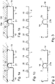
- Fig. 1a shows a sectional view of a first embodiment of a mounting profile 1 of the wall or ceiling paneling according to the invention.
- the mounting profile 1 comprises a channel 2.
- the channel 2 has a receiving opening 21 on the side facing the room to be cooled or heated, so that the channel 2 represents a receiving means 18 for a pipe register 6 of the cooling and/or heating system.
- This makes it possible to integrate a straight section 22 of the pipe register 6 in the mounting profile 1; in such a way that it can be easily mounted from the side or from below, since the receiving means 18 is open on one side 17.
- the room side 17 is the side facing the room to be heated or cooled.
- the flat areas between the individual channels 2 and their receiving openings 21 serve as a bearing surface 3 for the support and attachment of cover plates as a radiating plate or layer or the like.
- the mounting profile 1 has an angled portion 10 on its edge, with which it is attached to a ceiling or wall. On two opposite side surfaces 19, which extend parallel to the first mounting means 18, the mounting profile 1 has a concave bead-like configuration, so that a second mounting means 20 for the pipe register 6 of the cooling and/or heating system is formed between two adjacent mounting profiles becomes. Its receiving opening 21 also faces the room.
- Fig. 1b is a sectional view of a second embodiment of a mounting profile 1 of the wall or ceiling paneling according to the invention with a fastener.
- This embodiment makes up for that Fig. 1a except for an additional fastening means 18a, which is arranged in a recess of the first receiving means 18.
- a bead 18b is particularly preferably incorporated into the profile, which serves as a depression for the introduction of the fastening means 18a.
- the advantage of the solution according to the invention over the prior art is from 1c clearly showing a sectional view of an embodiment of the wall or ceiling paneling according to the invention.
- straight sections 22 of the pipeline register 6 can also be arranged in the intermediate spaces thanks to the configuration according to the invention of the side surface 19 of the individual profiles 1 .
- the first receiving means 18 and the second receiving means 20 complement each other in an ideal manner, so that a very homogeneous heat profile and/or cooling profile can be generated.
- the individual straight sections 22 of the pipeline register 6 are connected to one another by means of intermediate pieces or adapters.
- a first embodiment of an adapter 24 and its connection to the straight section 22 of the pipeline register 6 is in Figure 4a shown in section.
- the adapter 24, whose end portion is shown, has a self-tapping thread 30 at its free end.
- the adapter 24 is rotated into the straight section 22 with the thread 30 , where it cuts a thread at a constriction 31 in the straight section 22 and thus creates a connection between the adapter 24 and section 22 .
- connection is additionally sealed by sealing means, preferably two sealing means 25, which ensure the tightness of the connection against fluids in the pipelines even if the adapter 24 has a flange 24a, but this does not press directly onto the pipeline 22, but rather a distance "a" from the end of the pipeline.
- sealing means preferably two sealing means 25, which ensure the tightness of the connection against fluids in the pipelines even if the adapter 24 has a flange 24a, but this does not press directly onto the pipeline 22, but rather a distance "a" from the end of the pipeline.
- FIG. 4b An alternative type of connection between the adapter 24 and the pipe register 6 is in Figure 4b shown.
- a groove 27 is provided in a pipe wall 28 of the straight section 22 .
- a clamping ring 26 is arranged in the groove 27, over which the adapter 24 is pushed, so that the clamping ring 26 is located between an adapter wall 29 of the adapter 24 and the pipeline wall 28 of the straight section 22 and is clamped there.
- the adapter 24 is first pushed in the direction of the pipeline register 6. The clamping ring 26 cannot follow this movement since it is held in one position by the groove 27 .
- the adapter is removed a little from the pipeline register 6 again.
- the clamping ring 26 follows the movement since the groove 27 is ramped in cross-section in this direction as shown. Since the distance between the adapter wall 29 and the pipe wall 28 decreases in this direction, the clamping ring 26 is clamped between these two and thus contributes to an improved fixation of the adapter 24 and section 22 .
- Two sealing means 25, which surround the pipeline section and lie tightly against the adapter wall 29, provide additional sealing of the connection.
- This embodiment of the connection has the advantage that the adapter 24 does not have to be rotated in one direction when being fastened, but can be plugged in in the desired installation position. In addition, this embodiment is easier to manufacture in terms of manufacturing technology.
- the adapter 24 is also designed at its end engaging in the pipe in such a way that it can be easily pushed into the pipe and that in particular the seals are not damaged.
- the adapter 24 and section 22 of the pipeline register 6 is shown in plan view in FIG Figure 4c shown.
- the adapter 24 has two curved sections 32 so that it essentially describes a semicircle with which two parallel sections 22 are connected. This embodiment has the advantage that little space is required.
- FIG. 4d Yet another embodiment of the connection between the adapter 24 and the section 22 is in Figure 4d shown.
- the clamping ring 26 is arranged outside of the section 22 . It is clamped between the section 22 and a socket-shaped attachment and thus fulfills the same task as in the embodiment according to FIG Figure 4b .
- the clamping ring 26 in Figure 4d is located at the end of the adapter 24. So that the clamping ring 26 can fulfill its function, corresponding flange-like pressing elements 33 are provided, on which the clamping ring 26 is supported.
- the flange-like pressing elements 33 have, in particular, square or hexagonal approaches in order to ensure that the adapter is screwed in properly.
- the embodiment in Figure 4d is characterized in that the adapter 24 is guided over the tube 22 from the outside. It is assumed that the profile finishes together with the tube in terms of production technology. This is the case, for example, when a tube in the embodiments according to Figures 1a and 1b inserted or a register there is defective. Then a section is cut out and this is fitted with adapters at the end. For this purpose, a socket-like configuration of the adapter is provided, which is coupled to one another by means of appropriate connecting pieces.
- the adapter 24 can be constructed in several parts, both with regard to its radii of curvature and its composition from several individual elements.
- figure 5 is in section Another embodiment of the adapter according to the invention is shown in a multi-part structure.
- the adapter 24 has a transition piece 40 that creates the transition between the adapter 24 and the pipeline register 6 with the straight section 22 .
- the transition piece 40 has an internal thread which is screwed onto an external thread of the straight section 22 .
- the transition piece 40 also has an external thread at its opposite end onto which further elements of the adapter 24 can be screwed.
- such an element is a curved piece 42 with which the direction of flow is rotated by 90° with respect to the central axis of section 22 . Consequently, the crooked piece 42 has an internal thread at one end, with which it is screwed onto the transition piece 40 . At its other end, the crooked piece 42 has another internal thread.
- An intermediate piece 41 which has an external thread at both ends, can be screwed into this second internal thread of the crooked piece 42 or angle piece.
- the intermediate piece 41 is connected, for example, to a further crooked piece 42 which in turn is connected to a further section 22 .
- the components referred to as crooked pieces or angle pieces are also known as fittings in pipeline construction.
- the advantage of this embodiment is that when screwing the adapter into a pipeline, the multi-part design makes it possible to place the bends on a straight section, so that two pipes can be connected to one another.
- the receiving means is preferably designed as a channel, the width of which is dimensioned such that the pipeline register is held due to the tension force of the material of the mounting profile.
- the channel is in particular U-shaped and extends in the direction of the wall or ceiling at a distance from at least one bearing surface provided on the mounting profile and facing the room for cover plates or cover sheets of the wall or ceiling paneling.
- the receiving means designed as a channel is arranged between the two bearing surfaces, in particular in the middle.
- At least the receiving means has a curve on its side facing away from the room, which corresponds to the curve of the pipe or corresponds to it.
- a further development consists in that fastening elements are provided on the mounting profile or the cover plate for the detachable fixed fastening of the cover plate or cover sheet to the mounting profile.
- the wall or ceiling paneling is further developed in that the fastening means have adhesive or self-adhesive, adhesive or self-adhesive and/or magnetic properties and/or a Velcro fastener, preferably a Velcro strip, a clip connection, screw connection or the like is provided as the fastening element and/or the depth of the duct is dimensioned in such a way that fastening means guided through the cover plates, such as screws with self-tapping threads or the like, cannot reach or damage the pipeline register.
- the fastening means have adhesive or self-adhesive, adhesive or self-adhesive and/or magnetic properties and/or a Velcro fastener, preferably a Velcro strip, a clip connection, screw connection or the like is provided as the fastening element and/or the depth of the duct is dimensioned in such a way that fastening means guided through the cover plates, such as screws with self-tapping threads or the like, cannot reach or damage the pipeline register.
- a magnet in particular designed as a magnetic strip, is provided on at least one of the bearing surfaces in order to attach cover plates made of magnetically active material, such as sheet steel or steel foil, by the magnetic force and/or the mounting profile made of magnetically active material is formed and the cover plate has a correspondingly provided magnetic strip. It is preferred if the magnet or magnetic strip is arranged on the side of the mounting profile facing the ceiling or wall and the mounting profile or the side of the profile is arranged as a support in the installed state between the magnet and the covering layer. This arrangement is very clever because it means that there is no need for the additional attachment of the magnets, since it rests on the mounting profile when installed.
- a metal foil, a metal sheet, preferably coated with paint or foil, a plasterboard or Fermazell panel, a plastic panel, a PCM panel (phase change material) or the like can be used as the cover panel or sheet and/or the mounting profile on a substructure that forms the connection to the ceiling or wall.
- the cover plate or sheet can preferably be made of magnetically active material and/or transparent material, as a soundproofing element with perforations and/or as a cover element with a final surface, for example with a film coating or PCM coating and/or as a lighting element.
- the mounting profile can be arranged in or on a ceiling or wall element, for example as a corrugated sheet metal or trapezoidal sheet metal construction.
- the mounting profile can be molded into the corrugated sheet metal or trapezoidal sheet metal construction, or the mounting profile can be fastened in or on the corrugated sheet metal or trapezoidal sheet metal construction be.
- the receiving means for the pipe register can be located in the corrugations of the trapezoidal or corrugated sheet metal construction, the pipe register can be provided for accommodating a heating or cooling system, the pipe register can also be designed as a fuel-burning object.
- the pipeline register can also be designed at least partially as an empty pipe for cables, hoses or electrical heating conductors.
- the mounting profile in the trapezoidal or corrugated sheet metal construction can be arranged in a statically effective manner, the surface of the trapezoidal or corrugated sheet metal construction can be clad or laminated with statically effective material.
- the trapezoidal or corrugated sheet metal construction can be built up element-like, the entire surface of the element that faces the room can be designed as a heat or cold radiator.
- At least the side of the trapezoidal or corrugated iron construction facing the room can be provided with a heat-radiating coating for room heating based on the thermal radiation principle or a heat-absorbing coating for cooling
- the trapezoidal or corrugated iron construction can be designed as a sandwich element with a preferably integrated insulating material layer, the insulating material can have statically effective properties , or a surface coating can be provided, which preferably consists of thermally conductive material.
Landscapes
- Engineering & Computer Science (AREA)
- General Engineering & Computer Science (AREA)
- Chemical & Material Sciences (AREA)
- Thermal Sciences (AREA)
- Combustion & Propulsion (AREA)
- Mechanical Engineering (AREA)
- Physics & Mathematics (AREA)
- Building Environments (AREA)
- Supports For Pipes And Cables (AREA)
- Vehicle Interior And Exterior Ornaments, Soundproofing, And Insulation (AREA)
- Finishing Walls (AREA)
- Glass Compositions (AREA)
- Laminated Bodies (AREA)
Claims (15)
- Revêtement de mur ou de plafond comprenant un système de refroidissement et/ou de chauffage, le revêtement de mur ou de plafond comprenant au moins deux profilés de fixation (1) qui permettent de fixer le revêtement de mur ou de plafond au mur ou au plafond d'une construction, chacun des profilés de fixation (1) comportant sur un côté (17) dirigé vers la pièce à refroidir ou à chauffer un premier moyen de réception (18) qui est destiné à un tube ou un registre de canalisation (6) du système de refroidissement et/ou de chauffage et dont l'ouverture de réception est dirigée vers la pièce, le registre de canalisation (6) comportant au moins deux parties rectilignes (22) qui sont reliées de façon fixe au moyen de réception (18) dans le profilé de fixation respectif (1) pour former un élément de construction intégral, chaque partie rectiligne (22) du registre de canalisation (6) et le profilé de fixation respectif (1) formant un profilé commun qui peut être fabriqué en un seul processus de fabrication, à savoir dans un procédé d'extrusion, chacun des profilés de fixation (1) comportant deux surfaces d'appui (3) et le moyen de réception (18), conçu comme un canal (2), étant disposé entre les deux surfaces d'appui (3),les zones planes situées entre les canaux individuels (2) et leurs ouvertures de réception servant de surfaces d'appui (3) destinées au support et à la fixation de plaques de plafond telles qu'une plaque ou couche de rayonnement, caractérisé en ce quechaque profilé de fixation (1) présente au niveau de deux surfaces latérales opposées (19), qui s'étendent parallèlement au premier moyen de réception (18), une conformation concave de type moulure de manière à former entre deux profilés de fixation (1) adjacents un deuxième moyen de réception (20) qui est destiné au registre de canalisation (6) du système de refroidissement et/ou de chauffage et dont l'ouverture de réception est dirigée vers la pièce.
- Revêtement de mur ou de plafond selon la revendication 1, caractérisé en ce que la partie (22) a la forme d'un tube.
- Revêtement de mur ou de plafond selon l'une des revendications 1 ou 2, caractérisé en ce que la partie (22) est reliée fonctionnellement de manière au moins partiellement thermique au niveau de la circonférence au profilé de fixation (1), une surface de contact qui représente entre 50 et 100 % de la surface de circonférence de la partie (22) étant formée au niveau de la circonférence.
- Revêtement de mur ou de plafond selon l'une des revendications 1 à 3, caractérisé en ce que le profilé de fixation (1) et/ou une infrastructure, reliée au profilé de fixation (1), peuvent être activés thermiquement.
- Revêtement de mur ou de plafond selon l'une des revendications 1 à 4, caractérisé en ce que le profilé de fixation (1) peut être disposé ou fixé à l'aide de moyens de fixation appropriés (18a) soit directement au niveau d'une infrastructure comme par exemple un mur ou un plafond, soit sous la forme d'une construction suspendue et/ou en ce qu'un moyen de fixation (18a) peut être disposé dans un évidement du premier moyen de réception (18) et/ou en ce que le profilé de fixation (1) comporte au niveau de son bord un coude (10) permettant de le placer en appui, et en particulier de le fixer, au plafond ou au mur.
- Revêtement de mur ou de plafond selon l'une des revendications précédentes, caractérisé en ce que l'ouverture de réception (21) du profilé de fixation (1) comporte une paroi de recouvrement (23b) formant un seul plan avec le côté pièce (17), et de préférence le côté pièce (17) étant prévu comme support pour une couche rayonnant la chaleur pour le chauffage ou une couche absorbant la chaleur pour le refroidissement et/ou un aimant ou une bande magnétique étant disposé (e) du côté dirigé vers le mur ou le plafond de la construction afin de servir de moyen de fixation d'une plaque de recouvrement magnétique ou d'une couche de recouvrement magnétique, le profilé de fixation (1) étant disposé à l'état monté entre l'aimant ou la bande magnétique et la plaque de recouvrement.
- Revêtement de mur ou de plafond selon l'une des revendications précédentes, caractérisé en ce que la paroi de recouvrement (23b) a au moins une épaisseur minimale spécifiée.
- Revêtement de mur ou de plafond selon l'une des revendications précédentes, caractérisé en ce qu'une paroi de recouvrement (23b) ou un remplissage avec un matériau de remplissage (23a) dans un canal (2) formé par le premier moyen de réception (18) est prévu(e) comme moyen de protection contre un endommagement mécanique et/ou au moins un adaptateur (24) est prévu pour distribuer la chaleur ou relier des tubes individuels du registre de canalisation (6) pour le raccordement aux extrémités d'une partie rectiligne (22) ou d'un tube du registre de canalisation (6), l'adaptateur ayant de préférence un diamètre externe qui correspond essentiellement au diamètre interne de la partie rectiligne (24) de sorte que l'insertion par coulissement et/ou rotation de l'adaptateur (24) dans la partie rectiligne (22) du registre de canalisation (6) permette de réaliser une liaison par complémentarité de formes entre l'adaptateur (24) et la partie rectiligne du registre de canalisation (6).
- Revêtement de mur ou de plafond selon la revendication 8, caractérisé en ce qu'au moins un moyen d'étanchéité (25) est prévu entre l'adaptateur (24) et la partie rectiligne (22) du registre de canalisation (6) et/ou en ce que l'adaptateur (24) comporte à son extrémité libre un filetage auto-taraudeur (30) et la partie rectiligne (22) du registre de canalisation (6) comporte un rétrécissement (31) afin de relier l'adaptateur (24) par rotation à la partie rectiligne (22) .
- Revêtement de mur ou de plafond selon l'une des revendications précédentes 8 ou 9, caractérisé en ce qu'au moins une bague de serrage (26) est prévue entre l'adaptateur (24) et la partie rectiligne (22) du registre de canalisation (6) afin de centrer et/ou fixer l'adaptateur (24) dans la partie rectiligne (22) et/ou en ce que l'au moins une bague de serrage (26) est disposée entre l'adaptateur (24) et la partie rectiligne (22) du registre de canalisation (6) dans une gorge (27) ménagée dans une paroi de canalisation (28) de la partie rectiligne (22) de sorte que la bague de serrage (26) soit pressée entre la paroi (29) de l'adaptateur et une paroi de canalisation (28) de la partie rectiligne (22) lors du retrait de l'adaptateur (24) .
- Revêtement de mur ou de plafond selon la revendication 10, caractérisé en ce que la bague de serrage (26) est conçue comme un corps creux qui est en particulier rempli d'un liant qui s'échappe lors de l'éclatement du corps creux.
- Revêtement de mur ou de plafond selon l'une des revendications 1 à 10, caractérisé en ce que le filetage auto-taraudeur (30) est fixé à l'extrémité libre de la partie rectiligne (22) du registre de canalisation (6) et en ce que le registre de canalisation a un diamètre intérieur sensiblement constant.
- Revêtement de mur ou de plafond selon la revendication précédente et en lien avec la revendication 10, caractérisé en ce que la bague de serrage (26) est disposée à l'intérieur ou au niveau du filetage (30).
- Revêtement de mur ou de plafond selon la revendication 8 ou selon une revendication dépendant de celle-ci, caractérisé en ce que l'adaptateur (24) comporte deux parties coudées (32) afin de pouvoir relier deux parties rectilignes (22), situées côte à côte, du registre de canalisation (6) par l'adaptateur (24) et en particulier en ce que l'adaptateur (24) est conçu en plusieurs parties.
- Module, en particulier module préfabriqué, comprenant au moins un revêtement de mur ou de plafond selon l'une des revendications 1 à 14.
Priority Applications (2)
| Application Number | Priority Date | Filing Date | Title |
|---|---|---|---|
| SI201430829T SI2960585T1 (sl) | 2013-03-22 | 2014-03-21 | Stenska ali stropna obloga in modul s takšno |
| PL15177566.5T PL2960585T5 (pl) | 2013-03-22 | 2014-03-21 | Obudowa ściany albo sufitu i moduł wyposażony w taką obudowę |
Applications Claiming Priority (2)
| Application Number | Priority Date | Filing Date | Title |
|---|---|---|---|
| DE102013102990.6A DE102013102990A1 (de) | 2013-03-22 | 2013-03-22 | Wand- oder Deckenverkleidung |
| EP14161125.1A EP2781842B1 (fr) | 2013-03-22 | 2014-03-21 | Revêtement de mur ou de plafond |
Related Parent Applications (2)
| Application Number | Title | Priority Date | Filing Date |
|---|---|---|---|
| EP14161125.1A Division EP2781842B1 (fr) | 2013-03-22 | 2014-03-21 | Revêtement de mur ou de plafond |
| EP14161125.1A Division-Into EP2781842B1 (fr) | 2013-03-22 | 2014-03-21 | Revêtement de mur ou de plafond |
Publications (3)
| Publication Number | Publication Date |
|---|---|
| EP2960585A1 EP2960585A1 (fr) | 2015-12-30 |
| EP2960585B1 EP2960585B1 (fr) | 2018-05-16 |
| EP2960585B2 true EP2960585B2 (fr) | 2022-08-31 |
Family
ID=50343670
Family Applications (2)
| Application Number | Title | Priority Date | Filing Date |
|---|---|---|---|
| EP15177566.5A Active EP2960585B2 (fr) | 2013-03-22 | 2014-03-21 | Revetement de mur ou de plafond |
| EP14161125.1A Active EP2781842B1 (fr) | 2013-03-22 | 2014-03-21 | Revêtement de mur ou de plafond |
Family Applications After (1)
| Application Number | Title | Priority Date | Filing Date |
|---|---|---|---|
| EP14161125.1A Active EP2781842B1 (fr) | 2013-03-22 | 2014-03-21 | Revêtement de mur ou de plafond |
Country Status (10)
| Country | Link |
|---|---|
| EP (2) | EP2960585B2 (fr) |
| DE (1) | DE102013102990A1 (fr) |
| DK (2) | DK2960585T5 (fr) |
| ES (2) | ES2639714T3 (fr) |
| HR (1) | HRP20171347T1 (fr) |
| LT (1) | LT2781842T (fr) |
| PL (1) | PL2960585T5 (fr) |
| PT (1) | PT2781842T (fr) |
| RS (1) | RS56263B1 (fr) |
| SI (2) | SI2960585T1 (fr) |
Families Citing this family (3)
| Publication number | Priority date | Publication date | Assignee | Title |
|---|---|---|---|---|
| US11199368B2 (en) | 2015-08-31 | 2021-12-14 | Phase Change Energy Solutions, Inc. | Modular and portable fixtures containing a phase change material |
| DE102016120554A1 (de) | 2016-10-27 | 2018-05-03 | Liaver Gmbh & Co. Kg | Multifunktionale Deckenkonstruktion |
| DE102020204727A1 (de) * | 2020-04-15 | 2021-10-21 | Kermi Gmbh | Deckenstrahlelemente |
Citations (2)
| Publication number | Priority date | Publication date | Assignee | Title |
|---|---|---|---|---|
| NL9002091A (nl) † | 1990-09-25 | 1992-04-16 | Wegra Maschf Bv | Stralingspaneel. |
| EP0955503B1 (fr) † | 1998-05-06 | 2004-09-01 | Kurt Raschle | Elément rayonnant de plafond |
Family Cites Families (20)
| Publication number | Priority date | Publication date | Assignee | Title |
|---|---|---|---|---|
| DE1912396A1 (de) * | 1969-03-12 | 1970-09-24 | Welz Dipl Ing Hans Joachim | Deckenstrahlungsheizung bzw. -kuehlung |
| DE1922977A1 (de) | 1969-05-06 | 1970-12-23 | Schneider Anton Michael | Strahlungsplatte fuer Raumheizung und Halterung dazu |
| DK151834B (da) * | 1984-02-06 | 1988-01-04 | Elpan Aps | Lofts- eller vaegkonstruktion |
| US4759402A (en) * | 1987-08-17 | 1988-07-26 | Aero Tech Manufacturing Inc. | Modular construction for radiant panel |
| DE3919143A1 (de) * | 1989-06-12 | 1990-12-13 | Turbon Tunzini Klimatechnik | Flaechenfoermiges waermeaustauschelement zum heizen und kuehlen von raeumen |
| GB2262548A (en) | 1991-12-16 | 1993-06-23 | Hunter Douglas Ind Bv | Ceiling structure with heat transfer panel |
| DK172362B1 (da) * | 1996-10-24 | 1998-04-14 | Bjarne Kongsgaard | Varmeelement til et gulv |
| DE19739614A1 (de) | 1997-09-09 | 1999-03-25 | Erbsloeh Ag | Profil für eine Kühldecke, Kühlwand oder Boden |
| DE19803114C2 (de) * | 1998-01-28 | 2002-08-08 | Emcal Waermesysteme Gmbh | Wärmetauscherdecke mit Wärmeleitelementen |
| US6283382B1 (en) * | 2000-08-15 | 2001-09-04 | Michael Fitzemeyer | Radiant heating system pipe mounting plate |
| DE20105169U1 (de) * | 2001-03-23 | 2001-07-12 | Menge, Klaus, 64823 Groß-Umstadt | Strahlflächenaufbau |
| DE102006037484B4 (de) | 2006-08-10 | 2020-03-26 | Helmut Wollnitzke | Profilpaneel zum Heizen und/oder Kühlen eines Gebäuderaumes |
| US8256690B2 (en) * | 2007-04-27 | 2012-09-04 | Talbott Solar And Radiant Homes, Inc. | Radiant heating and cooling panel |
| HRP20211573T1 (hr) | 2007-06-18 | 2022-02-04 | Klima-Top Gmbh | Obloga za zid ili plafon |
| DE102008020422B4 (de) * | 2008-04-24 | 2018-02-15 | Phoenix Metall Gmbh | Heiz- oder Kühlelement mit einer Anschlussverrohrung |
| HUP0900577A2 (en) * | 2009-09-15 | 2011-03-28 | Bela Boldoghy | Heatframe element, and bordering surfaces of heat-discharger therewith, radiation heat absorber, and air heater as well as recooler |
| DE202010010564U1 (de) * | 2010-07-23 | 2010-10-14 | Gib Gesellschaft Für Innovative Bautechnologie Mbh | Heiz- oder Kühlelement für einen Deckenaufbau |
| DE202010010566U1 (de) * | 2010-07-23 | 2010-10-14 | Gib Gesellschaft Für Innovative Bautechnologie Mbh | Deckenaufbau |
| DE202010008798U1 (de) * | 2010-10-13 | 2012-01-17 | U.S.H.-Innovationen Gmbh | Verlegeplatte und Verlegesystem für Fußboden- und Wandheizleitungen |
| DE202010016878U1 (de) * | 2010-12-21 | 2012-03-22 | Gib Gesellschaft Für Innovative Bautechnologie Mbh | Aufbau eines Wärme leitenden Flächenelementes |
-
2013
- 2013-03-22 DE DE102013102990.6A patent/DE102013102990A1/de not_active Ceased
-
2014
- 2014-03-21 DK DK15177566.5T patent/DK2960585T5/da active
- 2014-03-21 ES ES14161125.1T patent/ES2639714T3/es active Active
- 2014-03-21 EP EP15177566.5A patent/EP2960585B2/fr active Active
- 2014-03-21 RS RS20170878A patent/RS56263B1/sr unknown
- 2014-03-21 SI SI201430829T patent/SI2960585T1/sl unknown
- 2014-03-21 ES ES15177566T patent/ES2684311T5/es active Active
- 2014-03-21 EP EP14161125.1A patent/EP2781842B1/fr active Active
- 2014-03-21 DK DK14161125.1T patent/DK2781842T3/en active
- 2014-03-21 SI SI201430369T patent/SI2781842T1/sl unknown
- 2014-03-21 PL PL15177566.5T patent/PL2960585T5/pl unknown
- 2014-03-21 PT PT141611251T patent/PT2781842T/pt unknown
- 2014-03-21 LT LTEP14161125.1T patent/LT2781842T/lt unknown
-
2017
- 2017-09-06 HR HRP20171347TT patent/HRP20171347T1/hr unknown
Patent Citations (2)
| Publication number | Priority date | Publication date | Assignee | Title |
|---|---|---|---|---|
| NL9002091A (nl) † | 1990-09-25 | 1992-04-16 | Wegra Maschf Bv | Stralingspaneel. |
| EP0955503B1 (fr) † | 1998-05-06 | 2004-09-01 | Kurt Raschle | Elément rayonnant de plafond |
Also Published As
| Publication number | Publication date |
|---|---|
| PL2960585T3 (pl) | 2018-10-31 |
| DK2960585T3 (en) | 2018-08-20 |
| DK2960585T5 (da) | 2023-02-20 |
| HRP20171347T1 (hr) | 2017-10-20 |
| HK1199298A1 (en) | 2015-06-26 |
| EP2781842B1 (fr) | 2017-06-07 |
| SI2960585T1 (sl) | 2018-10-30 |
| PT2781842T (pt) | 2017-09-12 |
| DE102013102990A1 (de) | 2014-09-25 |
| EP2781842A2 (fr) | 2014-09-24 |
| DK2960585T4 (da) | 2022-12-05 |
| HK1219528A1 (zh) | 2017-04-07 |
| DK2781842T3 (en) | 2017-09-18 |
| EP2781842A3 (fr) | 2014-12-31 |
| ES2684311T3 (es) | 2018-10-02 |
| ES2684311T5 (es) | 2022-11-22 |
| EP2960585B1 (fr) | 2018-05-16 |
| PL2960585T5 (pl) | 2023-01-09 |
| ES2639714T3 (es) | 2017-10-30 |
| RS56263B1 (sr) | 2017-11-30 |
| LT2781842T (lt) | 2017-09-25 |
| SI2781842T1 (sl) | 2017-10-30 |
| EP2960585A1 (fr) | 2015-12-30 |
Similar Documents
| Publication | Publication Date | Title |
|---|---|---|
| EP2006608B1 (fr) | Revêtement de mur ou de plafond | |
| EP2169316B1 (fr) | Plaque multicouche et plaque thermique | |
| EP2960585B2 (fr) | Revetement de mur ou de plafond | |
| EP3376129B1 (fr) | Traversée de paroi destinée à la connexion à un appareil domestique et procédé de montage d'une traversée de paroi | |
| DE202007014565U1 (de) | Wärmedämmverbundsystem | |
| DE102016100739A1 (de) | Verankerungs- und Dämmsystem für eine Verblendschale | |
| DE102012005655B4 (de) | Verfahren zur Herstellung einer Flächenheizung | |
| DE102013208284A1 (de) | Wärmedämmplatte und Verfahren zur Montage von Leitungen | |
| EP1688672B1 (fr) | Construction porteuse | |
| CH704894A2 (de) | Raumbegrenzungsaufbau, Verfahren zum Herstellen desselben und Element dafür. | |
| DE202009000976U1 (de) | Mehrschichtige Platte und Wärmeleitplatte | |
| DE10211469A1 (de) | Klimadecke aus Gipsplatten und Kapillarrohrmatten | |
| DE202007017185U1 (de) | Wärmeverbundsystem sowie ein Flächenheizungs/-kühlungs-Baukastensystem mit einem derartigen Wärmeverbundsystem | |
| WO2007042331A1 (fr) | Plaque d'echangeur thermique | |
| DE102015103018A1 (de) | Wärmeisolations- und Flächenheizsystem | |
| EP3887728B1 (fr) | Élément modulaire en forme de plaque pour réaliser un chauffage mural et système pour la réalisation modulaire d'une paroi en éléments chauffants muraux | |
| DE9314110U1 (de) | Plattenförmiger Wärmetauscher | |
| EP1672291B1 (fr) | Système de conditionnement d'air avec élément de climatisation | |
| DE8913991U1 (de) | Montagewand | |
| EP2674545A2 (fr) | Isolation comprenant des panneaux isolants avec des joints rainure-languette le long des bords | |
| DE102006008921A1 (de) | Wärmetauscherplatte | |
| EP1306624B1 (fr) | Elément de surface avec un dispositif de chauffage et/ou de refrigeration à grande surface intégré | |
| CH689899A5 (de) | Temperierbare Wand und Verfahren zur Herstellung der Wand. | |
| DE19738600A1 (de) | Vorwandinstallation | |
| AT409513B (de) | Plattenförmiges sandwichelement für den innenausbau |
Legal Events
| Date | Code | Title | Description |
|---|---|---|---|
| PUAI | Public reference made under article 153(3) epc to a published international application that has entered the european phase |
Free format text: ORIGINAL CODE: 0009012 |
|
| AC | Divisional application: reference to earlier application |
Ref document number: 2781842 Country of ref document: EP Kind code of ref document: P |
|
| AK | Designated contracting states |
Kind code of ref document: A1 Designated state(s): AL AT BE BG CH CY CZ DE DK EE ES FI FR GB GR HR HU IE IS IT LI LT LU LV MC MK MT NL NO PL PT RO RS SE SI SK SM TR |
|
| AX | Request for extension of the european patent |
Extension state: BA ME |
|
| 17P | Request for examination filed |
Effective date: 20160629 |
|
| RBV | Designated contracting states (corrected) |
Designated state(s): AL AT BE BG CH CY CZ DE DK EE ES FI FR GB GR HR HU IE IS IT LI LT LU LV MC MK MT NL NO PL PT RO RS SE SI SK SM TR |
|
| 17Q | First examination report despatched |
Effective date: 20161012 |
|
| STAA | Information on the status of an ep patent application or granted ep patent |
Free format text: STATUS: EXAMINATION IS IN PROGRESS |
|
| REG | Reference to a national code |
Ref country code: HK Ref legal event code: DE Ref document number: 1219528 Country of ref document: HK |
|
| GRAP | Despatch of communication of intention to grant a patent |
Free format text: ORIGINAL CODE: EPIDOSNIGR1 |
|
| STAA | Information on the status of an ep patent application or granted ep patent |
Free format text: STATUS: GRANT OF PATENT IS INTENDED |
|
| INTG | Intention to grant announced |
Effective date: 20171009 |
|
| GRAS | Grant fee paid |
Free format text: ORIGINAL CODE: EPIDOSNIGR3 |
|
| GRAA | (expected) grant |
Free format text: ORIGINAL CODE: 0009210 |
|
| STAA | Information on the status of an ep patent application or granted ep patent |
Free format text: STATUS: THE PATENT HAS BEEN GRANTED |
|
| AC | Divisional application: reference to earlier application |
Ref document number: 2781842 Country of ref document: EP Kind code of ref document: P |
|
| AK | Designated contracting states |
Kind code of ref document: B1 Designated state(s): AL AT BE BG CH CY CZ DE DK EE ES FI FR GB GR HR HU IE IS IT LI LT LU LV MC MK MT NL NO PL PT RO RS SE SI SK SM TR |
|
| REG | Reference to a national code |
Ref country code: GB Ref legal event code: FG4D Free format text: NOT ENGLISH |
|
| REG | Reference to a national code |
Ref country code: CH Ref legal event code: EP |
|
| REG | Reference to a national code |
Ref country code: IE Ref legal event code: FG4D Free format text: LANGUAGE OF EP DOCUMENT: GERMAN |
|
| REG | Reference to a national code |
Ref country code: DE Ref legal event code: R096 Ref document number: 502014008309 Country of ref document: DE |
|
| REG | Reference to a national code |
Ref country code: AT Ref legal event code: REF Ref document number: 999935 Country of ref document: AT Kind code of ref document: T Effective date: 20180615 |
|
| REG | Reference to a national code |
Ref country code: CH Ref legal event code: NV Representative=s name: ALDO ROEMPLER PATENTANWALT, CH |
|
| REG | Reference to a national code |
Ref country code: DK Ref legal event code: T3 Effective date: 20180814 |
|
| REG | Reference to a national code |
Ref country code: NL Ref legal event code: FP |
|
| REG | Reference to a national code |
Ref country code: SE Ref legal event code: TRGR |
|
| REG | Reference to a national code |
Ref country code: ES Ref legal event code: FG2A Ref document number: 2684311 Country of ref document: ES Kind code of ref document: T3 Effective date: 20181002 |
|
| REG | Reference to a national code |
Ref country code: LT Ref legal event code: MG4D |
|
| REG | Reference to a national code |
Ref country code: NO Ref legal event code: T2 Effective date: 20180516 |
|
| PG25 | Lapsed in a contracting state [announced via postgrant information from national office to epo] |
Ref country code: BG Free format text: LAPSE BECAUSE OF FAILURE TO SUBMIT A TRANSLATION OF THE DESCRIPTION OR TO PAY THE FEE WITHIN THE PRESCRIBED TIME-LIMIT Effective date: 20180816 Ref country code: LT Free format text: LAPSE BECAUSE OF FAILURE TO SUBMIT A TRANSLATION OF THE DESCRIPTION OR TO PAY THE FEE WITHIN THE PRESCRIBED TIME-LIMIT Effective date: 20180516 |
|
| PG25 | Lapsed in a contracting state [announced via postgrant information from national office to epo] |
Ref country code: HR Free format text: LAPSE BECAUSE OF FAILURE TO SUBMIT A TRANSLATION OF THE DESCRIPTION OR TO PAY THE FEE WITHIN THE PRESCRIBED TIME-LIMIT Effective date: 20180516 Ref country code: LV Free format text: LAPSE BECAUSE OF FAILURE TO SUBMIT A TRANSLATION OF THE DESCRIPTION OR TO PAY THE FEE WITHIN THE PRESCRIBED TIME-LIMIT Effective date: 20180516 Ref country code: RS Free format text: LAPSE BECAUSE OF FAILURE TO SUBMIT A TRANSLATION OF THE DESCRIPTION OR TO PAY THE FEE WITHIN THE PRESCRIBED TIME-LIMIT Effective date: 20180516 |
|
| REG | Reference to a national code |
Ref country code: GR Ref legal event code: EP Ref document number: 20180402276 Country of ref document: GR Effective date: 20190109 |
|
| REG | Reference to a national code |
Ref country code: DE Ref legal event code: R026 Ref document number: 502014008309 Country of ref document: DE |
|
| PG25 | Lapsed in a contracting state [announced via postgrant information from national office to epo] |
Ref country code: RO Free format text: LAPSE BECAUSE OF FAILURE TO SUBMIT A TRANSLATION OF THE DESCRIPTION OR TO PAY THE FEE WITHIN THE PRESCRIBED TIME-LIMIT Effective date: 20180516 Ref country code: SK Free format text: LAPSE BECAUSE OF FAILURE TO SUBMIT A TRANSLATION OF THE DESCRIPTION OR TO PAY THE FEE WITHIN THE PRESCRIBED TIME-LIMIT Effective date: 20180516 Ref country code: EE Free format text: LAPSE BECAUSE OF FAILURE TO SUBMIT A TRANSLATION OF THE DESCRIPTION OR TO PAY THE FEE WITHIN THE PRESCRIBED TIME-LIMIT Effective date: 20180516 |
|
| PLBI | Opposition filed |
Free format text: ORIGINAL CODE: 0009260 |
|
| PG25 | Lapsed in a contracting state [announced via postgrant information from national office to epo] |
Ref country code: SM Free format text: LAPSE BECAUSE OF FAILURE TO SUBMIT A TRANSLATION OF THE DESCRIPTION OR TO PAY THE FEE WITHIN THE PRESCRIBED TIME-LIMIT Effective date: 20180516 |
|
| PLAX | Notice of opposition and request to file observation + time limit sent |
Free format text: ORIGINAL CODE: EPIDOSNOBS2 |
|
| 26 | Opposition filed |
Opponent name: KERMI GMBH Effective date: 20190129 |
|
| PLBB | Reply of patent proprietor to notice(s) of opposition received |
Free format text: ORIGINAL CODE: EPIDOSNOBS3 |
|
| REG | Reference to a national code |
Ref country code: DE Ref legal event code: R082 Ref document number: 502014008309 Country of ref document: DE Representative=s name: PATENTANWAELTE OLBRICHT, BUCHHOLD, KEULERTZ PA, DE |
|
| PG25 | Lapsed in a contracting state [announced via postgrant information from national office to epo] |
Ref country code: MC Free format text: LAPSE BECAUSE OF FAILURE TO SUBMIT A TRANSLATION OF THE DESCRIPTION OR TO PAY THE FEE WITHIN THE PRESCRIBED TIME-LIMIT Effective date: 20180516 |
|
| PG25 | Lapsed in a contracting state [announced via postgrant information from national office to epo] |
Ref country code: AL Free format text: LAPSE BECAUSE OF FAILURE TO SUBMIT A TRANSLATION OF THE DESCRIPTION OR TO PAY THE FEE WITHIN THE PRESCRIBED TIME-LIMIT Effective date: 20180516 |
|
| PG25 | Lapsed in a contracting state [announced via postgrant information from national office to epo] |
Ref country code: IE Free format text: LAPSE BECAUSE OF NON-PAYMENT OF DUE FEES Effective date: 20190321 |
|
| PG25 | Lapsed in a contracting state [announced via postgrant information from national office to epo] |
Ref country code: MT Free format text: LAPSE BECAUSE OF FAILURE TO SUBMIT A TRANSLATION OF THE DESCRIPTION OR TO PAY THE FEE WITHIN THE PRESCRIBED TIME-LIMIT Effective date: 20180516 Ref country code: PT Free format text: LAPSE BECAUSE OF FAILURE TO SUBMIT A TRANSLATION OF THE DESCRIPTION OR TO PAY THE FEE WITHIN THE PRESCRIBED TIME-LIMIT Effective date: 20180917 |
|
| PG25 | Lapsed in a contracting state [announced via postgrant information from national office to epo] |
Ref country code: CY Free format text: LAPSE BECAUSE OF FAILURE TO SUBMIT A TRANSLATION OF THE DESCRIPTION OR TO PAY THE FEE WITHIN THE PRESCRIBED TIME-LIMIT Effective date: 20180516 |
|
| PGFP | Annual fee paid to national office [announced via postgrant information from national office to epo] |
Ref country code: SI Payment date: 20210310 Year of fee payment: 8 |
|
| PG25 | Lapsed in a contracting state [announced via postgrant information from national office to epo] |
Ref country code: IS Free format text: LAPSE BECAUSE OF FAILURE TO SUBMIT A TRANSLATION OF THE DESCRIPTION OR TO PAY THE FEE WITHIN THE PRESCRIBED TIME-LIMIT Effective date: 20180916 |
|
| PG25 | Lapsed in a contracting state [announced via postgrant information from national office to epo] |
Ref country code: HU Free format text: LAPSE BECAUSE OF FAILURE TO SUBMIT A TRANSLATION OF THE DESCRIPTION OR TO PAY THE FEE WITHIN THE PRESCRIBED TIME-LIMIT; INVALID AB INITIO Effective date: 20140321 |
|
| APBM | Appeal reference recorded |
Free format text: ORIGINAL CODE: EPIDOSNREFNO |
|
| APBP | Date of receipt of notice of appeal recorded |
Free format text: ORIGINAL CODE: EPIDOSNNOA2O |
|
| APAH | Appeal reference modified |
Free format text: ORIGINAL CODE: EPIDOSCREFNO |
|
| APBU | Appeal procedure closed |
Free format text: ORIGINAL CODE: EPIDOSNNOA9O |
|
| PGFP | Annual fee paid to national office [announced via postgrant information from national office to epo] |
Ref country code: GR Payment date: 20220323 Year of fee payment: 9 |
|
| PG25 | Lapsed in a contracting state [announced via postgrant information from national office to epo] |
Ref country code: MK Free format text: LAPSE BECAUSE OF FAILURE TO SUBMIT A TRANSLATION OF THE DESCRIPTION OR TO PAY THE FEE WITHIN THE PRESCRIBED TIME-LIMIT Effective date: 20180516 |
|
| PUAH | Patent maintained in amended form |
Free format text: ORIGINAL CODE: 0009272 |
|
| STAA | Information on the status of an ep patent application or granted ep patent |
Free format text: STATUS: PATENT MAINTAINED AS AMENDED |
|
| 27A | Patent maintained in amended form |
Effective date: 20220831 |
|
| AK | Designated contracting states |
Kind code of ref document: B2 Designated state(s): AL AT BE BG CH CY CZ DE DK EE ES FI FR GB GR HR HU IE IS IT LI LT LU LV MC MK MT NL NO PL PT RO RS SE SI SK SM TR |
|
| REG | Reference to a national code |
Ref country code: DE Ref legal event code: R102 Ref document number: 502014008309 Country of ref document: DE |
|
| REG | Reference to a national code |
Ref country code: ES Ref legal event code: DC2A Ref document number: 2684311 Country of ref document: ES Kind code of ref document: T5 Effective date: 20221122 |
|
| REG | Reference to a national code |
Ref country code: NL Ref legal event code: FP |
|
| REG | Reference to a national code |
Ref country code: DK Ref legal event code: T4 Effective date: 20221128 |
|
| REG | Reference to a national code |
Ref country code: SE Ref legal event code: RPEO |
|
| REG | Reference to a national code |
Ref country code: NO Ref legal event code: TB2 |
|
| REG | Reference to a national code |
Ref country code: SI Ref legal event code: KO00 Effective date: 20221122 |
|
| REG | Reference to a national code |
Ref country code: DE Ref legal event code: R081 Ref document number: 502014008309 Country of ref document: DE Owner name: P + R GMBH, DE Free format text: FORMER OWNER: BUEHLER, ARMIN, 87733 MARKT RETTENBACH, DE |
|
| REG | Reference to a national code |
Ref country code: GR Ref legal event code: EP Ref document number: 20220402343 Country of ref document: GR Effective date: 20230110 |
|
| REG | Reference to a national code |
Ref country code: DK Ref legal event code: T5 Effective date: 20230213 |
|
| REG | Reference to a national code |
Ref country code: DE Ref legal event code: R082 Ref document number: 502014008309 Country of ref document: DE Representative=s name: PATENTANWAELTE OLBRICHT, BUCHHOLD, KEULERTZ PA, DE Ref country code: DE Ref legal event code: R082 Ref document number: 502014008309 Country of ref document: DE Representative=s name: PFISTER, STEFAN, DIPL.-PHYS.UNIV., DE |
|
| PG25 | Lapsed in a contracting state [announced via postgrant information from national office to epo] |
Ref country code: SI Free format text: LAPSE BECAUSE OF NON-PAYMENT OF DUE FEES Effective date: 20220322 |
|
| REG | Reference to a national code |
Ref country code: HK Ref legal event code: AM43 Ref document number: 1219528 Country of ref document: HK |
|
| PG25 | Lapsed in a contracting state [announced via postgrant information from national office to epo] |
Ref country code: GR Free format text: LAPSE BECAUSE OF NON-PAYMENT OF DUE FEES Effective date: 20231009 |
|
| PG25 | Lapsed in a contracting state [announced via postgrant information from national office to epo] |
Ref country code: GR Free format text: LAPSE BECAUSE OF NON-PAYMENT OF DUE FEES Effective date: 20231009 |
|
| PGFP | Annual fee paid to national office [announced via postgrant information from national office to epo] |
Ref country code: NL Payment date: 20240320 Year of fee payment: 11 |
|
| PGFP | Annual fee paid to national office [announced via postgrant information from national office to epo] |
Ref country code: FI Payment date: 20240320 Year of fee payment: 11 |
|
| PGFP | Annual fee paid to national office [announced via postgrant information from national office to epo] |
Ref country code: SE Payment date: 20240320 Year of fee payment: 11 Ref country code: NO Payment date: 20240322 Year of fee payment: 11 Ref country code: DK Payment date: 20240326 Year of fee payment: 11 |
|
| REG | Reference to a national code |
Ref country code: DE Ref legal event code: R082 Ref document number: 502014008309 Country of ref document: DE Representative=s name: PFISTER, STEFAN, DIPL.-PHYS.UNIV., DE |
|
| PGFP | Annual fee paid to national office [announced via postgrant information from national office to epo] |
Ref country code: IT Payment date: 20250227 Year of fee payment: 12 |
|
| PGFP | Annual fee paid to national office [announced via postgrant information from national office to epo] |
Ref country code: ES Payment date: 20250402 Year of fee payment: 12 |
|
| PGFP | Annual fee paid to national office [announced via postgrant information from national office to epo] |
Ref country code: CH Payment date: 20250401 Year of fee payment: 12 |
|
| PG25 | Lapsed in a contracting state [announced via postgrant information from national office to epo] |
Ref country code: FI Free format text: LAPSE BECAUSE OF NON-PAYMENT OF DUE FEES Effective date: 20250321 |
|
| REG | Reference to a national code |
Ref country code: DK Ref legal event code: EBP Effective date: 20250331 |
|
| REG | Reference to a national code |
Ref country code: SE Ref legal event code: EUG |
|
| REG | Reference to a national code |
Ref country code: NL Ref legal event code: MM Effective date: 20250401 |
|
| PG25 | Lapsed in a contracting state [announced via postgrant information from national office to epo] |
Ref country code: NL Free format text: LAPSE BECAUSE OF NON-PAYMENT OF DUE FEES Effective date: 20250401 |
|
| PG25 | Lapsed in a contracting state [announced via postgrant information from national office to epo] |
Ref country code: NO Free format text: LAPSE BECAUSE OF NON-PAYMENT OF DUE FEES Effective date: 20250331 |
|
| PG25 | Lapsed in a contracting state [announced via postgrant information from national office to epo] |
Ref country code: SE Free format text: LAPSE BECAUSE OF NON-PAYMENT OF DUE FEES Effective date: 20250322 |
|
| REG | Reference to a national code |
Ref country code: CH Ref legal event code: U11 Free format text: ST27 STATUS EVENT CODE: U-0-0-U10-U11 (AS PROVIDED BY THE NATIONAL OFFICE) Effective date: 20260401 |
|
| PGFP | Annual fee paid to national office [announced via postgrant information from national office to epo] |
Ref country code: GB Payment date: 20260324 Year of fee payment: 13 |
|
| PG25 | Lapsed in a contracting state [announced via postgrant information from national office to epo] |
Ref country code: DK Free format text: LAPSE BECAUSE OF NON-PAYMENT OF DUE FEES Effective date: 20250331 |
|
| PGFP | Annual fee paid to national office [announced via postgrant information from national office to epo] |
Ref country code: DE Payment date: 20251203 Year of fee payment: 13 |
|
| PGFP | Annual fee paid to national office [announced via postgrant information from national office to epo] |
Ref country code: AT Payment date: 20260319 Year of fee payment: 13 |
|
| PGFP | Annual fee paid to national office [announced via postgrant information from national office to epo] |
Ref country code: BE Payment date: 20260323 Year of fee payment: 13 Ref country code: LU Payment date: 20260320 Year of fee payment: 13 |
|
| PGFP | Annual fee paid to national office [announced via postgrant information from national office to epo] |
Ref country code: FR Payment date: 20260325 Year of fee payment: 13 |
|
| PGFP | Annual fee paid to national office [announced via postgrant information from national office to epo] |
Ref country code: TR Payment date: 20260316 Year of fee payment: 13 |
|
| PGFP | Annual fee paid to national office [announced via postgrant information from national office to epo] |
Ref country code: CZ Payment date: 20260306 Year of fee payment: 13 |
|
| PGFP | Annual fee paid to national office [announced via postgrant information from national office to epo] |
Ref country code: PL Payment date: 20260311 Year of fee payment: 13 |