EP2985490A1 - Vorrichtung und verfahren zur herstellung einer knöchelklammer - Google Patents
Vorrichtung und verfahren zur herstellung einer knöchelklammer Download PDFInfo
- Publication number
- EP2985490A1 EP2985490A1 EP14783164.8A EP14783164A EP2985490A1 EP 2985490 A1 EP2985490 A1 EP 2985490A1 EP 14783164 A EP14783164 A EP 14783164A EP 2985490 A1 EP2985490 A1 EP 2985490A1
- Authority
- EP
- European Patent Office
- Prior art keywords
- workpiece
- pair
- support shaft
- attachment parts
- width
- Prior art date
- Legal status (The legal status is an assumption and is not a legal conclusion. Google has not performed a legal analysis and makes no representation as to the accuracy of the status listed.)
- Withdrawn
Links
Images





Classifications
-
- B—PERFORMING OPERATIONS; TRANSPORTING
- B21—MECHANICAL METAL-WORKING WITHOUT ESSENTIALLY REMOVING MATERIAL; PUNCHING METAL
- B21D—WORKING OR PROCESSING OF SHEET METAL OR METAL TUBES, RODS OR PROFILES WITHOUT ESSENTIALLY REMOVING MATERIAL; PUNCHING METAL
- B21D53/00—Making other particular articles
-
- B—PERFORMING OPERATIONS; TRANSPORTING
- B21—MECHANICAL METAL-WORKING WITHOUT ESSENTIALLY REMOVING MATERIAL; PUNCHING METAL
- B21D—WORKING OR PROCESSING OF SHEET METAL OR METAL TUBES, RODS OR PROFILES WITHOUT ESSENTIALLY REMOVING MATERIAL; PUNCHING METAL
- B21D53/00—Making other particular articles
- B21D53/36—Making other particular articles clips, clamps, or like fastening or attaching devices, e.g. for electric installation
-
- B—PERFORMING OPERATIONS; TRANSPORTING
- B21—MECHANICAL METAL-WORKING WITHOUT ESSENTIALLY REMOVING MATERIAL; PUNCHING METAL
- B21D—WORKING OR PROCESSING OF SHEET METAL OR METAL TUBES, RODS OR PROFILES WITHOUT ESSENTIALLY REMOVING MATERIAL; PUNCHING METAL
- B21D28/00—Shaping by press-cutting; Perforating
- B21D28/24—Perforating, i.e. punching holes
- B21D28/32—Perforating, i.e. punching holes in other articles of special shape
-
- B—PERFORMING OPERATIONS; TRANSPORTING
- B21—MECHANICAL METAL-WORKING WITHOUT ESSENTIALLY REMOVING MATERIAL; PUNCHING METAL
- B21D—WORKING OR PROCESSING OF SHEET METAL OR METAL TUBES, RODS OR PROFILES WITHOUT ESSENTIALLY REMOVING MATERIAL; PUNCHING METAL
- B21D35/00—Combined processes according to or processes combined with methods covered by groups B21D1/00 - B21D31/00
- B21D35/001—Shaping combined with punching, e.g. stamping and perforating
-
- B—PERFORMING OPERATIONS; TRANSPORTING
- B60—VEHICLES IN GENERAL
- B60G—VEHICLE SUSPENSION ARRANGEMENTS
- B60G13/00—Resilient suspensions characterised by arrangement, location or type of vibration dampers
- B60G13/001—Arrangements for attachment of dampers
- B60G13/005—Arrangements for attachment of dampers characterised by the mounting on the axle or suspension arm of the damper unit
-
- B—PERFORMING OPERATIONS; TRANSPORTING
- B60—VEHICLES IN GENERAL
- B60G—VEHICLE SUSPENSION ARRANGEMENTS
- B60G7/00—Pivoted suspension arms; Accessories thereof
-
- F—MECHANICAL ENGINEERING; LIGHTING; HEATING; WEAPONS; BLASTING
- F16—ENGINEERING ELEMENTS AND UNITS; GENERAL MEASURES FOR PRODUCING AND MAINTAINING EFFECTIVE FUNCTIONING OF MACHINES OR INSTALLATIONS; THERMAL INSULATION IN GENERAL
- F16F—SPRINGS; SHOCK-ABSORBERS; MEANS FOR DAMPING VIBRATION
- F16F9/00—Springs, vibration-dampers, shock-absorbers, or similarly-constructed movement-dampers using a fluid or the equivalent as damping medium
- F16F9/32—Details
- F16F9/3207—Constructional features
- F16F9/3235—Constructional features of cylinders
- F16F9/3242—Constructional features of cylinders of cylinder ends, e.g. caps
-
- F—MECHANICAL ENGINEERING; LIGHTING; HEATING; WEAPONS; BLASTING
- F16—ENGINEERING ELEMENTS AND UNITS; GENERAL MEASURES FOR PRODUCING AND MAINTAINING EFFECTIVE FUNCTIONING OF MACHINES OR INSTALLATIONS; THERMAL INSULATION IN GENERAL
- F16F—SPRINGS; SHOCK-ABSORBERS; MEANS FOR DAMPING VIBRATION
- F16F9/00—Springs, vibration-dampers, shock-absorbers, or similarly-constructed movement-dampers using a fluid or the equivalent as damping medium
- F16F9/32—Details
- F16F9/54—Arrangements for attachment
-
- B—PERFORMING OPERATIONS; TRANSPORTING
- B60—VEHICLES IN GENERAL
- B60G—VEHICLE SUSPENSION ARRANGEMENTS
- B60G2200/00—Indexing codes relating to suspension types
- B60G2200/10—Independent suspensions
- B60G2200/14—Independent suspensions with lateral arms
- B60G2200/142—Independent suspensions with lateral arms with a single lateral arm, e.g. MacPherson type
-
- B—PERFORMING OPERATIONS; TRANSPORTING
- B60—VEHICLES IN GENERAL
- B60G—VEHICLE SUSPENSION ARRANGEMENTS
- B60G2204/00—Indexing codes related to suspensions per se or to auxiliary parts
- B60G2204/40—Auxiliary suspension parts; Adjustment of suspensions
- B60G2204/43—Fittings, brackets or knuckles
- B60G2204/4304—Bracket for lower cylinder mount of McPherson strut
Definitions
- the present invention relates to an apparatus and method for manufacturing a knuckle bracket for attaching a shock absorber to a vehicle.
- JP1997-89036A discloses a conventional knuckle bracket including a curved part extending in an axial direction and linear parts formed on both ends in the circumferential direction of the curved part, in which a lower end part of a hydraulic shock absorber is inserted and fixed inside the curved part. Attachment holes into which bolts for attaching to a vehicle are inserted are formed in the pair of linear parts.
- the curved part and the linear parts are molded by blank machining and then bending a plate material, and finally the attachment holes are formed by punching holes in the pair of linear parts.
- the holes can also be punched prior to blank machining, but in this method it is difficult to ensure the coaxiality of the attachment holes formed in the pair of linear parts.
- the holes are generally punched last in the manufacturing process.
- An object of the present invention is to reduce the manufacturing costs of a knuckle bracket.
- a knuckle bracket includes a bracket main body that has an inner peripheral shape along a tube of a shock absorber and is fixed to the tube and a pair of attachment parts that are formed to protrude parallel to each other from both ends of the bracket main body and are fastened to a steering knuckle.
- the apparatus for manufacturing the knuckle bracket includes: a support shaft that has an outer peripheral shape along the inner peripheral shape of the bracket main body and supports a workpiece; a width molding machine that molds a width of the pair of attachment parts to a predetermined dimension in a state in which the workpiece is supported on the support shaft; and a hole punching machine that machines attachment holes into the pair of attachment parts in a state in which the workpiece is supported on the support shaft and the pair of attachment parts are facing both side surfaces of a die.
- the workpiece is transported from the width molding machine to the hole punching machine by moving the workpiece along the support shaft until the workpiece is above the die after the support shaft is raised and then lowering the support shaft until the support shaft abuts a top surface of the die.
- a knuckle bracket includes a bracket main body that has an inner peripheral shape along a tube of a shock absorber and is fixed to the tube and a pair of attachment parts that are formed to protrude parallel to each other from both ends of the bracket main body and are fastened to a steering knuckle.
- the method for manufacturing the knuckle bracket includes: a width molding step in which a width of the pair of attachment parts is molded to a predetermined dimension; and a hole punching step in which attachment holes are machined into the pair of attachment parts in a state in which the pair of attachment parts are facing both side surfaces of a die.
- the width molding step and the hole punching step are carried out in a state in which the workpiece is supported on a support shaft that has an outer peripheral shape along the inner peripheral shape of the bracket main body.
- the workpiece is transported from the width molding step to the hole punching step by moving the workpiece along the support shaft until the workpiece is above the die after the support shaft is raised and then lowering the support shaft until the support shaft abuts a top surface of the die.
- a manufacturing apparatus 100 for a knuckle bracket 1 according to an embodiment of the present invention will now be explained.
- the knuckle bracket 1 is for attaching a shock absorber to a steering knuckle of a vehicle.
- the knuckle bracket 1 includes a bracket main body 2 that has a C-shaped cross-section and an inner peripheral shape that follows a tube 10 of a shock absorber, a pair of attachment parts 3 and 4 that are formed to protrude parallel to each other from both ends of the bracket main body 2 and are fastened to a steering knuckle, and a pair of ribs 5 and 6 serving as deflected parts that are formed to deflect to the inside from the ends of the pair of attachment parts 3 and 4.
- the bracket main body 2 is fixed by welding to a bottom part of the tube 10 of the shock absorber in a state in which it encloses the tube 10.
- the pair of ribs 5 and 6 is for increasing the strength of the attachment parts 3 and 4.
- the knuckle bracket 1 is molded in a process beginning with blank machining in which a metallic plate material is machined and followed by a press molding step, a rib bending and molding step, a bending and molding step, a width molding step, and a hole punching step as shown in FIGS. 2A to 2E .
- a substrate of the knuckle bracket 1 is punched from the metallic plate material.
- the press molding step the substrate obtained by the blank machining is press molded to mold the area that will become the bracket main body 2 and the areas that will become the attachment parts 3 and 4.
- the ribs 5 and 6 are molded by bending.
- the bracket main body 2 is molded by bending.
- the width molding step the width of the pair of attachment parts 3 and 4 is molded to a predetermined dimension.
- the hole punching step the attachment holes 3a and 4a are machined in the pair of attachment parts 3 and 4.
- the manufacturing apparatus 100 will now be explained referring to FIGS. 3 to 14 .
- the manufacturing apparatus 100 consecutively executes the following steps with a transfer press: the press molding step, the rib bending and molding step, the bending and molding step, the width molding step, and the hole punching step.
- the manufacturing apparatus 100 has dedicated metal molds for executing each step, and automatically machines the workpiece 9 consecutively as the workpiece 9 is transported to the metal molds for each step in order.
- the manufacturing apparatus 100 includes a press machine that executes the press molding step, a rib bending and molding machine that executes the rib bending and molding step, a bending and molding machine that executes the bending and molding step, a width molding machine 30 that executes the width molding step, and a hole punching machine 40 that executes the hole punching step.
- a press machine that executes the press molding step
- a rib bending and molding machine that executes the rib bending and molding step
- a bending and molding machine that executes the bending and molding step
- a width molding machine 30 that executes the width molding step
- a hole punching machine 40 that executes the hole punching step.
- the manufacturing apparatus 100 includes a top frame 62 configured such that it can move up and down.
- Dedicated metal molds 31 and 41 for executing the width molding step and the hole punching step are provided on the top frame 62.
- a drive source for moving the top frame 62 up and down for example, a hydraulic cylinder or a servo motor can be used.
- the workpiece 9 is automatically machined by transporting the workpiece 9 to the width molding machine 30 and the hole punching machine 40 by a transport mechanism (not illustrated) in sync with the reciprocal movement of the top frame 62 between the top dead center as shown in FIG. 3 and the bottom dead center as shown in FIG. 9 .
- the workpiece is transported in a state in which the top frame 62 is positioned at the top dead center, and the molding of each step is executed as the top frame 62 lowers from the top dead center to the bottom dead center.
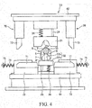
- FIGS. 3 to 5 illustrate a state in which the top frame 62 is positioned at the top dead center
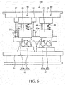
- FIGS. 6 to 8 illustrate a state in which the top frame 62 is positioned between the top dead center and the bottom dead center
- FIGS. 9 to 11 illustrate a state in which the top frame 62 is positioned at the bottom dead center.
- the width molding machine 30 will be explained referring to FIGS. 3 , 4 , 6 , 7 , 9 , and 10 .
- the width molding machine 30 includes a receiving die 32 provided on a bottom frame 61 such that it can move up and down, a core mold 33 serving as a support shaft that supports the workpiece 9, a metal mold 31 that is provided on the top frame 62 and supports the workpiece 9 between itself and the core mold 33 during the width molding step of the pair of attachment parts 3 and 4, and a compression mechanism 70 that compresses the pair of attachment parts 3 and 4 to the receiving die 32.
- the receiving die 32 includes a base 32a and a receiving part 32b that is positioned between the pair of attachment parts 3 and 4 and defines the width dimension of the pair of attachment parts 3 and 4.
- the base 32a is supported on the bottom frame 61 via a guide pin 35 that can freely slide in the bottom frame 61 and a spring 36.
- the core mold 33 is a cylindrical mold that has an outer peripheral shape that follows an inner peripheral shape of the bracket main body 2.
- the core mold 33 is formed to be joined to an upper end of the receiving part 32b of the receiving die 32. In this way, the core mold 33 and the receiving die 32 are integrally formed.
- the core mold 33 is formed to extend to the hole punching machine 40 of the subsequent step, and is used for both the width molding step and the hole punching step.
- the metal mold 31 is suspended downward from the top frame 62 via a guide pin 39 that can freely slide in the top frame 62 and a spring 38.
- the metal mold 31 has a mold milling 31a that follows the outer peripheral shape of the bracket main body 2.
- a pair of gas cylinders 37 is provided on the top frame 62.
- Pins 37a are provided on rod tips of the gas cylinders 37.
- the gas cylinders 37 cause the core mold 33 to lower when the pins 37a abut the core mold 33 before the metal mold 31 abuts the workpiece 9 when the top frame 62 lowers from the top dead center to the bottom dead center.
- the gas cylinders 37 are not illustrated.
- the compression mechanism 70 includes sliders 71 that are provided such that they can freely slide on both sides of the receiving die 32 and impart a compressive force on the pair of attachment parts 3 and 4, support bases 72 that are provided on the bottom frame 61 and support the sliders 71, and wedge cams 73 that are provided on both sides of the metal mold 31 on the top frame 62 and cause the sliders 71 to advance toward the receiving part 32b and generate a compressive force.
- An inclined surface corresponding to the inclined surface of the wedge cam 73 is formed on the back surface of each slider 71.
- the workpiece 9 is transported from the bending and molding machine, which is the previous step, to the width molding machine 30 in a state in which the top frame 62 is positioned at the top dead center.
- the receiving die 32 is biased by the biasing force of the spring 36, and the core mold 33 is raised to its maximum height (the state shown in FIGS. 3 and 4 ).
- the workpiece 9 is gripped and transported by transport fingers provided on the transport mechanism and supported on the core mold 33. In this way, the workpiece 9 is transported from the bending and molding machine to the width molding machine 30.
- the pins 37a of the gas cylinders 37 abut the core mold 33 and the core mold 33 is pushed down and lowered by the gas cylinders 37.
- the receiving die 32 that is integral with the core mold 33 is lowered while compressing the spring 36 to abut the bottom frame 61 (the state shown in FIGS. 6 and 7 ).
- the sliders 71 enter a state in which they can advance forward without interfering with the base 32a of the receiving die 32.
- the core mold 33 that is integral with the receiving die 32 is positioned at its minimum height.
- the wedge cams 73 are pushed against the sliders 71 and the sliders 71 proceed forward.
- the sliders 71 push against the pair of attachment parts 3 and 4 toward the receiving part 32b.
- the width of the attachment parts 3 and 4 becomes approximately equal to the width of the receiving part 32b, and thus the width of the attachment parts 3 and 4 can be molded to a desired dimension by adjusting the width of the receiving part 32b.
- the workpiece 9 is supported on the core mold 33 so that the ribs 5 and 6 follow the edge surfaces of the receiving part 32b without interfering with the receiving part 32b, or in other words so that the ribs 5 and 6 do not interfere with the receiving part 32b and inhibit the width molding.
- the workpiece 9 is transported to the core mold 33 from the bending and molding machine, which is the previous step, the workpiece 9 is positioned relative to the receiving part 32b.
- the positioning of the workpiece 9 is carried out by, for example, controlling the amount of movement of the workpiece 9 with a servo motor that drives the transport fingers.
- the hole punching machine 40 includes a receiving die 42 provided on the bottom frame 61, the core mold 33 that is shared by the width molding machine 30 and supports the workpiece 9, a metal mold 41 that is provided on the top frame 62 and supports the workpiece 9 between itself and the core mold 33 during the machining of the attachment holes 3a and 4a, punches 43 that punch the attachment holes 3a and 4a in the pair of attachment parts 3 and 4, and a driving mechanism 80 that drives the punches 43.
- the receiving die 42 includes a base 42a and a receiving part 42b that is sandwiched by the pair of attachment parts 3 and 4 during machining of the attachment holes 3a and 4a.
- a through hole 42c (refer to FIGS. 12 and 13 ) into which the punches 43 enter during machining of the attachment holes 3a and 4a is formed in the receiving part 42b.
- the metal mold 41 is suspended downward from the top frame 62 via a guide pin 44 that can freely slide in the top frame 62 and a spring 45.
- the metal mold 41 has a mold milling 41a that follows the outer peripheral shape of the bracket main body 2.
- the driving mechanism 80 includes sliders 81 which are provided on both sides of the receiving die 42 such that they can freely move in the axial direction of the punches 43 and support the punches 43, support bases 82 that are provided on the bottom frame 61 and support the sliders 81, and wedge cams 83 that are provided on both sides of the metal mold 41 on the top frame 62 and cause the sliders 81 to advance toward the receiving part 42b.
- An inclined surface corresponding to the inclined surface of the wedge cam 83 is formed on the back surface of each slider 81.
- Strippers 87 that push portions of the attachment parts 3 and 4 outside of those to be punched to prevent deformation of the attachment parts 3 and 4 when the attachment parts 3 and 4 are punched by the punches 43 are provided on the punches 43.
- the punches 43 penetrate through the strippers 87, and springs 88 are interposed between the strippers 87 and the sliders 81.
- the workpiece 9 is transported from the width molding machine 30, which is the previous step, to the hole punching machine 40 in a state in which the top frame 62 is positioned at the top dead center.
- the core mold 33 is positioned at its maximum height (the state shown in FIG. 3 ).
- the workpiece 9, which is supported on the core mold 33 upon completion of width molding by the width molding machine 30, is gripped by the transport fingers provided on the transport mechanism to slide it along the core mold 33 and move it until it is above the receiving die 42.
- the height of the core mold 33 is set such that the workpiece 9 does not interfere with the receiving part 42b of the receiving die 42, or in other words such that the sliding of the workpiece 9 is not inhibited by the receiving part 42b.
- the core mold 33 is lowered until it abuts the top surface of the receiving part 42b by the action of the gas cylinders 37 (the state shown in FIGS. 6 and 8 ). In this state, the pair of attachment parts 3 and 4 sandwich both side surfaces of the receiving part 42b, and the ribs 5 and 6 follow the edge surfaces of the receiving part 42b without interfering with the receiving part 42b. In this way, the core mold 33 is lowered such that the ribs 5 and 6 do not interfere with the receiving part 42b.
- the workpiece 9 is supported on the core mold 33 such that the ribs 5 and 6 do not interfere with the receiving part 42b when the core mold 33 is lowered. Specifically, when the workpiece 9 is transported by sliding along the core mold 33, the workpiece 9 is positioned relative to the receiving part 42b. The positioning of the workpiece 9 is carried out by, for example, controlling the amount of movement of the workpiece 9 with a servo motor that drives the transport fingers.
- the pushing of the gas cylinders 37 on the core mold 33 and the biasing of the metal mold 41 by the spring 45 are released.
- the core mold 33 enters a state in which it has risen to its maximum height due to the biasing force of the spring 36 of the width molding machine 30 (the state shown in FIG. 3 ).
- the machining of the attachment holes 3a and 4a is carried out consecutively with the width molding of the pair of attachment parts 3 and 4, and a dedicated press machine is not needed. Therefore, the manufacturing costs of the knuckle bracket 1 can be reduced.
- the workpiece 9 is transported from the width molding machine 30 to the hole punching machine 40 by moving the workpiece 9 along the core mold 33 until the workpiece 9 is above the receiving die 42 after the core mold 33 is raised and then lowering the core mold 33 until the core mold 33 abuts the top surface of the receiving part 42b of the receiving die 42. In this way, the workpiece 9 is set on the receiving part 42b from above the receiving part 42b.
- the workpiece 9 is set on the receiving part 42b from above the receiving part 42b.
- the workpiece 9 is set on the receiving part 42b by only sliding it along the core mold 33. In this case, it would be necessary to shape the receiving part 42b as shown by the diagonal lines in FIG.
- the workpiece 9 is set on the receiving part 42b from above the receiving part 42b, and thus it is not necessary to provide the neck part 95 to the receiving part 42b as shown in FIGS. 12 and 13 and the rigidity of the receiving part 42b can be secured. In this way, in the present embodiment, since the workpiece 9 is set on the receiving part 42b from above the receiving part 42b, the width molding step and the hole punching step can be consecutively carried out.
Landscapes
- Engineering & Computer Science (AREA)
- Mechanical Engineering (AREA)
- General Engineering & Computer Science (AREA)
- Shaping Metal By Deep-Drawing, Or The Like (AREA)
- Bending Of Plates, Rods, And Pipes (AREA)
- Steering-Linkage Mechanisms And Four-Wheel Steering (AREA)
- Vehicle Body Suspensions (AREA)
- Fluid-Damping Devices (AREA)
Applications Claiming Priority (2)
| Application Number | Priority Date | Filing Date | Title |
|---|---|---|---|
| JP2013081779A JP6043230B2 (ja) | 2013-04-10 | 2013-04-10 | ナックルブラケットの製造装置及び製造方法 |
| PCT/JP2014/059207 WO2014168028A1 (ja) | 2013-04-10 | 2014-03-28 | ナックルブラケットの製造装置及び製造方法 |
Publications (2)
| Publication Number | Publication Date |
|---|---|
| EP2985490A1 true EP2985490A1 (de) | 2016-02-17 |
| EP2985490A4 EP2985490A4 (de) | 2017-01-11 |
Family
ID=51689438
Family Applications (1)
| Application Number | Title | Priority Date | Filing Date |
|---|---|---|---|
| EP14783164.8A Withdrawn EP2985490A4 (de) | 2013-04-10 | 2014-03-28 | Vorrichtung und verfahren zur herstellung einer knöchelklammer |
Country Status (6)
| Country | Link |
|---|---|
| US (1) | US9895738B2 (de) |
| EP (1) | EP2985490A4 (de) |
| JP (1) | JP6043230B2 (de) |
| CN (1) | CN105051405B (de) |
| TW (1) | TW201446355A (de) |
| WO (1) | WO2014168028A1 (de) |
Families Citing this family (15)
| Publication number | Priority date | Publication date | Assignee | Title |
|---|---|---|---|---|
| JP6043230B2 (ja) * | 2013-04-10 | 2016-12-14 | Kyb株式会社 | ナックルブラケットの製造装置及び製造方法 |
| KR101615617B1 (ko) | 2015-06-04 | 2016-04-26 | 정태열 | 자동차용 쇼바 가공장치 |
| US10456821B2 (en) * | 2015-10-14 | 2019-10-29 | Magna Powertrain Inc. | Fine blanking cam die |
| FR3049327B1 (fr) * | 2016-03-24 | 2018-08-17 | Akwel Sweden Ab | Procede de fabrication pour realiser un assemblage de support et tuyauterie |
| JP6956596B2 (ja) * | 2017-11-06 | 2021-11-02 | Kyb株式会社 | シリンダ装置、及びシリンダ装置の製造方法 |
| WO2019106924A1 (ja) * | 2017-11-28 | 2019-06-06 | 日立オートモティブシステムズ株式会社 | シリンダ装置の製造方法 |
| KR102069102B1 (ko) * | 2017-12-14 | 2020-01-22 | 주식회사 미래브이씨 | 디스크 챔버에 적용되는 클램프 링의 제조 방법 |
| JP6650504B1 (ja) * | 2018-11-29 | 2020-02-19 | ティエフオー株式会社 | 金型装置及びこれを用いた成形物の製造方法 |
| CN110102639B (zh) * | 2019-04-10 | 2020-12-04 | 苏州威博达汽车零部件有限公司 | 一种汽车座椅骨架的冲压成型复合模具及其加工工艺 |
| CN111361378A (zh) * | 2020-03-21 | 2020-07-03 | 南京金龙客车制造有限公司 | 一种纯电动客车减振器支架锁紧控制策略 |
| JP7177970B2 (ja) * | 2020-07-06 | 2022-11-24 | Kyb株式会社 | 緩衝器 |
| CN112404213A (zh) * | 2020-10-10 | 2021-02-26 | 赖春娣 | 一种建筑用三角铁板制造设备 |
| US11596995B2 (en) * | 2021-06-21 | 2023-03-07 | Morton Industries LLC | Bending die assembly with split die and method for using |
| CN113477822A (zh) * | 2021-08-02 | 2021-10-08 | 西安外事学院 | 一种机械配件成型用高效冲压设备 |
| CN113500134A (zh) * | 2021-08-20 | 2021-10-15 | 台州市中亚汽车零部件股份有限公司 | 一种冷冲压多孔成型模具 |
Family Cites Families (22)
| Publication number | Priority date | Publication date | Assignee | Title |
|---|---|---|---|---|
| US2676638A (en) * | 1952-07-26 | 1954-04-27 | Richard Seifried | Stretch-wrap forming machine |
| JPS51107268A (ja) * | 1975-03-18 | 1976-09-22 | Aihara Seisakusho Kk | Hoosubandonoseizohohotosonosochi |
| US4491339A (en) * | 1981-12-30 | 1985-01-01 | Kayaba Kkk | Strut for McPherson type automobile suspensions |
| JP2529038Y2 (ja) * | 1990-08-15 | 1997-03-12 | カヤバ工業株式会社 | ナックルブラケット |
| JPH08210421A (ja) * | 1994-11-28 | 1996-08-20 | Unisia Jecs Corp | 液圧緩衝器 |
| JP3264416B2 (ja) | 1995-09-26 | 2002-03-11 | 株式会社ユニシアジェックス | 液圧緩衝器の取付ブラケット |
| JP2000018309A (ja) * | 1998-07-01 | 2000-01-18 | Kayaba Ind Co Ltd | ナックルブラケット |
| JP2000154842A (ja) * | 1998-11-18 | 2000-06-06 | Kayaba Ind Co Ltd | ナックルブラケット |
| EP1180441A1 (de) * | 2000-08-16 | 2002-02-20 | Delphi Technologies, Inc. | Schweisslose Befestigung eines Befestigungsbügels auf einem Behälterrohr eines Federbeines einer Aufhängungsanordnung |
| JP4371342B2 (ja) * | 2000-09-01 | 2009-11-25 | 株式会社ショーワ | 油圧緩衝器のチューブ構造及びチューブ製造方法 |
| DE60142580D1 (de) * | 2000-12-26 | 2010-08-26 | Kayaba Industry Co Ltd | Verfahren zur herstellung einer äusseren verkleidungseinheit |
| DE10115373C1 (de) * | 2001-03-28 | 2002-10-17 | Zf Sachs Ag | Gelenkstütze für ein Kolben-Zylinderaggregat |
| JP2004069019A (ja) * | 2002-08-09 | 2004-03-04 | Kayaba Ind Co Ltd | ナックルブラケット |
| JP2004197847A (ja) * | 2002-12-18 | 2004-07-15 | Showa Corp | 油圧緩衝器のナックルブラケット構造 |
| JP2005046902A (ja) * | 2003-07-31 | 2005-02-24 | Tokico Ltd | 三重接合体およびその製造方法 |
| JP2005188648A (ja) * | 2003-12-25 | 2005-07-14 | Showa Corp | 油圧緩衝器のナックルブラケット構造 |
| US20080066289A1 (en) * | 2006-09-12 | 2008-03-20 | Kayaba Industry Co., Ltd. | Through-hole stamping method in bracket made of bent plate |
| JP5032173B2 (ja) * | 2007-03-29 | 2012-09-26 | カヤバ工業株式会社 | 穴開け装置及び穴開け方法 |
| JP5166077B2 (ja) * | 2008-03-07 | 2013-03-21 | カヤバ工業株式会社 | ナックルブラケット |
| CN201223898Y (zh) * | 2008-07-25 | 2009-04-22 | 南阳淅减汽车减振器有限公司 | 减振器下支架横向冲孔模具 |
| JP6043230B2 (ja) * | 2013-04-10 | 2016-12-14 | Kyb株式会社 | ナックルブラケットの製造装置及び製造方法 |
| US10092945B2 (en) * | 2014-09-04 | 2018-10-09 | Bayloff Die & Machine Co., Inc. | Apparatus for and method of forming a metal strut |
-
2013
- 2013-04-10 JP JP2013081779A patent/JP6043230B2/ja active Active
-
2014
- 2014-03-28 WO PCT/JP2014/059207 patent/WO2014168028A1/ja not_active Ceased
- 2014-03-28 US US14/781,574 patent/US9895738B2/en not_active Expired - Fee Related
- 2014-03-28 EP EP14783164.8A patent/EP2985490A4/de not_active Withdrawn
- 2014-03-28 CN CN201480017670.2A patent/CN105051405B/zh not_active Expired - Fee Related
- 2014-04-01 TW TW103112105A patent/TW201446355A/zh not_active IP Right Cessation
Also Published As
| Publication number | Publication date |
|---|---|
| EP2985490A4 (de) | 2017-01-11 |
| TW201446355A (zh) | 2014-12-16 |
| JP6043230B2 (ja) | 2016-12-14 |
| US20160059298A1 (en) | 2016-03-03 |
| US9895738B2 (en) | 2018-02-20 |
| WO2014168028A1 (ja) | 2014-10-16 |
| CN105051405A (zh) | 2015-11-11 |
| JP2014202344A (ja) | 2014-10-27 |
| CN105051405B (zh) | 2016-10-19 |
| TWI562840B (de) | 2016-12-21 |
Similar Documents
| Publication | Publication Date | Title |
|---|---|---|
| US9895738B2 (en) | Apparatus and method for manufacturing a knuckle bracket | |
| US8627565B2 (en) | Method for producing crankshaft and production apparatus therefor | |
| CN104220184B (zh) | 由金属板制至少局部闭合的型材或管状构件的装置和方法 | |
| JP5713309B2 (ja) | アンダーカット処理機構 | |
| US20080041243A1 (en) | Linear motor mounted press machine and press working method | |
| JP2003220426A (ja) | 中空材の穴明方法及び中空材の穴明装置 | |
| JP5630820B2 (ja) | パネルアセンブリの製造方法及びこのアセンブリのへミング加工装置 | |
| JP4970900B2 (ja) | プレス加工法およびそれに用いる成形装置 | |
| CN111097837A (zh) | 圆管零件反向冲孔模具 | |
| JP2017121644A (ja) | プレス成形装置、及びプレス成形方法 | |
| JP2003230921A (ja) | 複合加工プレス型 | |
| CN217290035U (zh) | 冲压加工系统 | |
| JP5032173B2 (ja) | 穴開け装置及び穴開け方法 | |
| CN211839971U (zh) | 一种干簧管切断弯折装置 | |
| JP5999982B2 (ja) | 鍛造部品の製造方法および鍛造部品の製造装置 | |
| CN210253758U (zh) | 一种管件液压成形压力机 | |
| JP6767063B2 (ja) | 絞り成形装置 | |
| JP5799526B2 (ja) | プレスシャフトの製造方法 | |
| CN213052279U (zh) | 一种铝合金钣金件的冲压成型装置 | |
| JP2008246490A (ja) | 穴開け装置及び穴開け方法 | |
| KR20210017804A (ko) | 프레스 장치 | |
| JP6481362B2 (ja) | 歯車成型用金型装置 | |
| CN211539208U (zh) | 一种冲孔一体化的内高压成型模具 | |
| CN213256400U (zh) | 一种双工位导向压力机 | |
| JP2008213019A (ja) | 薄板打抜き加工方法及び打抜き加工装置 |
Legal Events
| Date | Code | Title | Description |
|---|---|---|---|
| PUAI | Public reference made under article 153(3) epc to a published international application that has entered the european phase |
Free format text: ORIGINAL CODE: 0009012 |
|
| 17P | Request for examination filed |
Effective date: 20151105 |
|
| AK | Designated contracting states |
Kind code of ref document: A1 Designated state(s): AL AT BE BG CH CY CZ DE DK EE ES FI FR GB GR HR HU IE IS IT LI LT LU LV MC MK MT NL NO PL PT RO RS SE SI SK SM TR |
|
| AX | Request for extension of the european patent |
Extension state: BA ME |
|
| DAX | Request for extension of the european patent (deleted) | ||
| A4 | Supplementary search report drawn up and despatched |
Effective date: 20161212 |
|
| RIC1 | Information provided on ipc code assigned before grant |
Ipc: B60G 13/00 20060101ALI20161206BHEP Ipc: B21D 7/022 20060101ALI20161206BHEP Ipc: F16F 9/32 20060101ALI20161206BHEP Ipc: B60G 7/00 20060101ALI20161206BHEP Ipc: B21D 35/00 20060101ALI20161206BHEP Ipc: B21D 53/36 20060101ALI20161206BHEP Ipc: B21D 28/32 20060101ALI20161206BHEP Ipc: B21D 53/00 20060101ALI20161206BHEP Ipc: F16F 9/54 20060101AFI20161206BHEP |
|
| RIC1 | Information provided on ipc code assigned before grant |
Ipc: F16F 9/54 20060101AFI20180309BHEP Ipc: F16F 9/32 20060101ALI20180309BHEP Ipc: B60G 13/00 20060101ALI20180309BHEP Ipc: B21D 53/36 20060101ALI20180309BHEP Ipc: B60G 7/00 20060101ALI20180309BHEP Ipc: B21D 28/32 20060101ALI20180309BHEP Ipc: B21D 35/00 20060101ALI20180309BHEP Ipc: B21D 53/00 20060101ALI20180309BHEP Ipc: B21D 7/022 20060101ALI20180309BHEP |
|
| GRAP | Despatch of communication of intention to grant a patent |
Free format text: ORIGINAL CODE: EPIDOSNIGR1 |
|
| INTG | Intention to grant announced |
Effective date: 20180424 |
|
| STAA | Information on the status of an ep patent application or granted ep patent |
Free format text: STATUS: THE APPLICATION IS DEEMED TO BE WITHDRAWN |
|
| 18D | Application deemed to be withdrawn |
Effective date: 20180905 |