EP2987910A1 - Fraiseuse automobile, et procede d'evacuation de produit de fraisage - Google Patents
Fraiseuse automobile, et procede d'evacuation de produit de fraisage Download PDFInfo
- Publication number
- EP2987910A1 EP2987910A1 EP15180914.2A EP15180914A EP2987910A1 EP 2987910 A1 EP2987910 A1 EP 2987910A1 EP 15180914 A EP15180914 A EP 15180914A EP 2987910 A1 EP2987910 A1 EP 2987910A1
- Authority
- EP
- European Patent Office
- Prior art keywords
- conveyor belt
- milling machine
- transport vehicle
- signal
- machine
- Prior art date
- Legal status (The legal status is an assumption and is not a legal conclusion. Google has not performed a legal analysis and makes no representation as to the accuracy of the status listed.)
- Granted
Links
Images



Classifications
-
- E—FIXED CONSTRUCTIONS
- E01—CONSTRUCTION OF ROADS, RAILWAYS, OR BRIDGES
- E01C—CONSTRUCTION OF, OR SURFACES FOR, ROADS, SPORTS GROUNDS, OR THE LIKE; MACHINES OR AUXILIARY TOOLS FOR CONSTRUCTION OR REPAIR
- E01C23/00—Auxiliary devices or arrangements for constructing, repairing, reconditioning, or taking-up road or like surfaces
- E01C23/01—Devices or auxiliary means for setting-out or checking the configuration of new surfacing, e.g. templates, screed or reference line supports; Applications of apparatus for measuring, indicating, or recording the surface configuration of existing surfacing, e.g. profilographs
-
- B—PERFORMING OPERATIONS; TRANSPORTING
- B65—CONVEYING; PACKING; STORING; HANDLING THIN OR FILAMENTARY MATERIAL
- B65G—TRANSPORT OR STORAGE DEVICES, e.g. CONVEYORS FOR LOADING OR TIPPING, SHOP CONVEYOR SYSTEMS OR PNEUMATIC TUBE CONVEYORS
- B65G67/00—Loading or unloading vehicles
- B65G67/02—Loading or unloading land vehicles
- B65G67/04—Loading land vehicles
- B65G67/22—Loading moving vehicles
-
- B—PERFORMING OPERATIONS; TRANSPORTING
- B65—CONVEYING; PACKING; STORING; HANDLING THIN OR FILAMENTARY MATERIAL
- B65G—TRANSPORT OR STORAGE DEVICES, e.g. CONVEYORS FOR LOADING OR TIPPING, SHOP CONVEYOR SYSTEMS OR PNEUMATIC TUBE CONVEYORS
- B65G41/00—Supporting frames or bases for conveyors as a whole, e.g. transportable conveyor frames
- B65G41/001—Supporting frames or bases for conveyors as a whole, e.g. transportable conveyor frames with the conveyor adjustably mounted on the supporting frame or base
- B65G41/002—Pivotably mounted
-
- E—FIXED CONSTRUCTIONS
- E01—CONSTRUCTION OF ROADS, RAILWAYS, OR BRIDGES
- E01C—CONSTRUCTION OF, OR SURFACES FOR, ROADS, SPORTS GROUNDS, OR THE LIKE; MACHINES OR AUXILIARY TOOLS FOR CONSTRUCTION OR REPAIR
- E01C23/00—Auxiliary devices or arrangements for constructing, repairing, reconditioning, or taking-up road or like surfaces
- E01C23/06—Devices or arrangements for working the finished surface; Devices for repairing or reconditioning the surface of damaged paving; Recycling in place or on the road
- E01C23/08—Devices or arrangements for working the finished surface; Devices for repairing or reconditioning the surface of damaged paving; Recycling in place or on the road for roughening or patterning; for removing the surface down to a predetermined depth high spots or material bonded to the surface, e.g. markings; for maintaining earth roads, clay courts or like surfaces by means of surface working tools, e.g. scarifiers, levelling blades
- E01C23/085—Devices or arrangements for working the finished surface; Devices for repairing or reconditioning the surface of damaged paving; Recycling in place or on the road for roughening or patterning; for removing the surface down to a predetermined depth high spots or material bonded to the surface, e.g. markings; for maintaining earth roads, clay courts or like surfaces by means of surface working tools, e.g. scarifiers, levelling blades using power-driven tools, e.g. vibratory tools
- E01C23/088—Rotary tools, e.g. milling drums
-
- E—FIXED CONSTRUCTIONS
- E01—CONSTRUCTION OF ROADS, RAILWAYS, OR BRIDGES
- E01C—CONSTRUCTION OF, OR SURFACES FOR, ROADS, SPORTS GROUNDS, OR THE LIKE; MACHINES OR AUXILIARY TOOLS FOR CONSTRUCTION OR REPAIR
- E01C23/00—Auxiliary devices or arrangements for constructing, repairing, reconditioning, or taking-up road or like surfaces
- E01C23/06—Devices or arrangements for working the finished surface; Devices for repairing or reconditioning the surface of damaged paving; Recycling in place or on the road
- E01C23/12—Devices or arrangements for working the finished surface; Devices for repairing or reconditioning the surface of damaged paving; Recycling in place or on the road for taking-up, tearing-up, or full-depth breaking-up paving, e.g. sett extractor
- E01C23/122—Devices or arrangements for working the finished surface; Devices for repairing or reconditioning the surface of damaged paving; Recycling in place or on the road for taking-up, tearing-up, or full-depth breaking-up paving, e.g. sett extractor with power-driven tools, e.g. oscillated hammer apparatus
- E01C23/127—Devices or arrangements for working the finished surface; Devices for repairing or reconditioning the surface of damaged paving; Recycling in place or on the road for taking-up, tearing-up, or full-depth breaking-up paving, e.g. sett extractor with power-driven tools, e.g. oscillated hammer apparatus rotary, e.g. rotary hammers
Definitions
- the invention relates to a self-propelled milling machine according to the preamble of claim 1, a method for unloading milled material according to the preamble of claim 10, as well as a road or floor processing unit according to claim 15.
- the milling machine has a control for the driving and milling operation and a work roll for milling z.
- B. a road surface.
- a conveyor belt device for. B. a conveyor belt device with at least one conveyor belt.
- the conveyor belt device has a discharge end, on which the milled material is unloaded due to the conveying speed via a trajectory in the form of a trajectory parabola onto the loading surface of the at least one transport vehicle.
- the transport direction of the last or only conveyor belt of the conveyor belt device can be pivoted relative to the longitudinal axis of the milling machine laterally at a predetermined pivot angle to the left or right and be height adjustable over a predetermined elevation angle.
- the conveying speed of the conveyor belt can be adjustable.
- the milled material is thrown forward on the preceding vehicle.
- the operator of the milling machine must signal to the driver of the transport vehicle when the transport vehicle to move forward and when it should stop. This causes problems because the operator basically has to focus on the milling operation while avoiding a collision with the preceding transport vehicle.
- the information is communicated via a horn, so that as soon as the driver of the transport vehicle hears the horn, the transport vehicle is advanced by a certain distance.
- the problem here is the situation in which the driver of the transport vehicle overhears the horn signal, or if another passing vehicle a. Horn signal outputs.
- Another problem is that the operator must take over the loading of the loading surface by adjusting the pivot angle, the elevation angle and the conveying speed of the transport direction last or only conveyor belt of the conveyor belt device and thereby perform its actual task, the milling operation, is distracted.
- a correction of the swivel angle may be necessary, for example, when changing the steering direction of the milling machine.
- the invention is therefore based on the object of specifying a self-propelled milling machine, as well as a method for unloading milled material of a milling machine, prevent damage to the milling machine during coordination of the unloading process in all operating situations.
- the invention advantageously provides that a detection device is arranged on the underside of the conveyor belt, with which an activation signal can be triggered in the event of the conveyor belt approaching an object, in particular the rear wall of the loading surface.
- a particular advantage of the detection device is that it is independent of the movements of the transport vehicle and the milling machine relative to each other.
- the detection device has at least one surface-shaped or at least one line-shaped probe element.
- a probe element can detect at the bottom of the conveyor belt over a longer distance below the conveyor belt contact with an object early and independently of the pivot position of the conveyor belt.
- the feeler element extends symmetrically to a longitudinal central axis of the conveyor belt and / or extends at substantially parallel distance from the conveyor belt. In this way, a collision can be detected in time without damaging the conveyor belt at the bottom and / or the collision object.
- the feeler element can be flexible and consist of a pull rope or of a flexible fabric and extends linearly.
- the flexible probe element can also be deflected to maintain a substantially uniform distance to the underside of the conveyor belt and to adapt to a curved shape of the conveyor belt.
- the probe element is rigid and consists of a z. B. rectangular plate element.
- the flexible or rigid sensing element of the detection device acts in the event of contact with the rear wall of a cargo area or other object on the sensor, which generates the activation signal and passes to the controller.
- a tensile force can be detected at the ends of the element, which results from the deflection of the probe element.
- a rigid probe element can be fastened, for example, parallelogram-like on the conveyor belt, so that the deflection of the suspension can be detected by the sensor.
- control in the presence of an activation signal generates a control signal for reducing the propulsion speed or machine stop and / or increases the elevation angle of the conveyor belt and / or generates a drive signal for the driver of the transport vehicle.
- control generates an alarm signal and / or a signal for slowing down the conveyor belt speed in the presence of an activation signal.
- the deceleration of the conveyor belt speed is used to ensure that no milled material is unloaded onto the roof of the cab of the transport vehicle by the parcels for the milled material is shortened.
- the probe element can be coupled to at least one mechanically actuatable or capacitive or inductive or optoelectronic sensor.
- the probe element may be formed from a plurality of capacitive or inductive or optoelectronic sensors arranged distributed linearly or over a surface.
- the probe element can be formed from at least one light barrier.
- a detection device is used, with the case of approach of the conveyor belt to an object, in particular the rear wall of the cargo area, an activation signal is generated.
- the controller comprises a detection and control unit that automatically controls the positioning of a point of impact of the material to be milled.
- Such control allows the operator of the milling machine to concentrate on the milling operation and travel along a predetermined milling track. In this way, an automatic unloading process is realized, which ensures even during cornering for an automatic coordination of the unloading process with the movement of the milling machine and the transport vehicle.
- the pivot angle of the transport direction in the last or single conveyor belt of the conveyor belt device depending on the steering angle of the self-propelled milling machine can be controlled.
- Fig. 1 shows a milling machine 1 using the example of a muzzle-loader road milling machine 1a.
- the milling machine 1 has a machine frame 2, which is supported by an existing example of crawler tracks or wheels chassis 4, which is connected via at least three height adjustment devices in the form of lifting columns 5 with the machine frame 2.
- How out Fig. 2 seen, in the embodiment, four lifting columns 5 are provided, with which the machine frame 2 can be brought into a predetermined plane, which preferably runs parallel to the road surface 6, on which the crawler tracks of the chassis 4 are.
- Fig. 1 Road milling machine shown has a work roll 22 in the longitudinal direction of the milling machine 1 a between the crawler tracks of the chassis 4.
- the milling machines 1a, 1b may have track wheels and / or wheels.
- the work roll can be height-adjustable via the lifting frame 5 carrying the machine frame 2 or relative to the machine frame 2.
- a milling machine 1 b may include the work roll 22, for example, at the level of the rear crawler tracks or wheels of the chassis 4.
- the conveyor belt device with at least one conveyor belt 11,12 for removal of the milled milled material at the front 7 or rear end 8 of the milling machine 1a, 1b may be arranged.
- Fig.2 shows the example of a back-loading milling machine 1b, in which the transport vehicle 10 travels behind behind the milling machine 1 in reverse.
- the transport vehicle 10 can, as in Fig. 3 shown to be moved in forward travel before the milling machine 1 on a different lane.
- the milled material milled by the work roll 22 is loaded onto the loading surface 15 of the transport vehicle 10 via a first stationary conveyor belt 11 of the conveyor belt device, which transfers the milled material 14 to a second, pivotable conveyor belt 12. Due to the speed of the conveyor belt 12, the milled material 14 is not unloaded directly at the end of the conveyor belt 12, but the milled material follows a pitch parabola, so that the point of impact 16 is located on the loading surface 15 at a distance from the free end 13 of the conveyor belt 12.
- the conveyor belt 12 can be pivoted from a central position to the left or to the right via piston-cylinder units 18 in order to unload the material to be milled 14 even when cornering or when tracked driving the transport vehicle 10 on the bed 15.
- the driver of the milling machine 1 a, 1 b can adjust the elevation angle of the conveyor belt 12 with the aid of a piston-cylinder unit 20.
- the elevation angle like the conveying speed of the conveyor belt 12, influences the parabola of the milled material 14 and the position of the point of impact 16.
- the currently set elevation angle about a horizontal first axis 21 or pivoting angle about a vertical second axis 23 is reported to a detection and control unit 24, which further comprises at least one detector 26, the position of the loading surface 15 and / or in the transport direction last or single conveyor belt 12 continuously detected.
- This detector 26 can either be arranged on the milling machine 1a, 1b at the end facing the conveyor belt device or at the free end 13 of the conveyor belt 12.
- the detection and control unit 24 may be integrated in the controller 3 for the driving and milling operation or at least connected to this, possibly also data on the driving speed and / or a detected steering angle of the milling machine 1a, 1b and the conveying speed of the conveyor belt 12 to get.
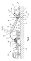
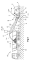
- FIGS. 1 and 2 show at the bottom of the conveyor belt 12, a detection device 50, which has a line-shaped feeler element 52.
- the feeler element 52 may for example consist of at least one cable-shaped or wire-shaped element which extends substantially parallel with distance from the conveyor belt 12 and is clamped at its ends so that at least one sensor 56 can detect a deflection of the button 52.
- the feeler element 52 preferably extends symmetrically to a longitudinal central axis 40 of the conveyor belt 12, as best of the FIGS. 5 and 6 is apparent.
- the feeler element 52 can be formed, for example, from wire ropes ( Fig. 6 ) or from a flexible sheet which is fastened in a manner similar to the line-shaped feeler such that a deflection of the fabric upon contact with an article or with the back wall 60 of the transport vehicle 10 via at least one sensor 56 triggers an activation signal, the control 3 can be fed.
- the probe element may also consist of a rigid plate member, which, as in the FIGS. 4 and 5 shown, parallelogram-like attached to the conveyor belt 12.
- the sensors 56 can be z. B. designed as a rotation angle sensors that can detect a movement of the suspension 54 at the joints. It is understood that the plate-shaped probe element 52 can be held by spring force in its unloaded position, for example, and is deflected only in the event of contact with an object.
- the sensing elements 52 may each be coupled to at least one mechanically operable sensor or to a capacitive or inductive or optoelectronic sensor.
- the detection device 50 in the areas in the FIGS. 1 to 6 apparent flexible or rigid sensing elements 52 may be formed of a plurality of linear or area distributed distributed capacitive or inductive or optoelectronic sensors 58.
- the detection device 50 z. B. in the from FIGS. 1 to 6 apparent areas of the flexible or rigid sensing elements 52 may be formed from at least one light barrier 54.
- the longitudinal extent of the detection device 50 may extend substantially over the major part of the length of the conveyor belt 12, as in Fig. 1 shown or extend only to a section of interest, as in the FIGS. 2 and 4 shown.
- the detection and control unit 24 can locate the variable position of the loading surface 15 of the transport vehicle 10 and the conveyor belt 12 relative to the machine frame 2 and the positioning of the point of impact 16 of the material to be milled 14 over the swing angle and / or elevation angle and / or the conveying speed of the conveyor belt device continuously and automatically control, so that the discarded milled material 14 at least impinges within the loading area 15.
- the variable position of the loading surface 15 of the transport vehicle 10 relative to the conveyor belt 12 can be continuously located to perform the control.
Landscapes
- Engineering & Computer Science (AREA)
- Mechanical Engineering (AREA)
- Architecture (AREA)
- Civil Engineering (AREA)
- Structural Engineering (AREA)
- Mining & Mineral Resources (AREA)
- Aviation & Aerospace Engineering (AREA)
- Disintegrating Or Milling (AREA)
- Road Repair (AREA)
- Control Of Position, Course, Altitude, Or Attitude Of Moving Bodies (AREA)
- Control Of Conveyors (AREA)
Applications Claiming Priority (1)
| Application Number | Priority Date | Filing Date | Title |
|---|---|---|---|
| DE102014216603.9A DE102014216603B4 (de) | 2014-08-21 | 2014-08-21 | Selbstfahrende Fräsmaschine, sowie Verfahren zum Abladen von Fräsgut |
Publications (2)
| Publication Number | Publication Date |
|---|---|
| EP2987910A1 true EP2987910A1 (fr) | 2016-02-24 |
| EP2987910B1 EP2987910B1 (fr) | 2018-01-03 |
Family
ID=53969161
Family Applications (1)
| Application Number | Title | Priority Date | Filing Date |
|---|---|---|---|
| EP15180914.2A Active EP2987910B1 (fr) | 2014-08-21 | 2015-08-13 | Fraiseuse automotrice, et procédé d'évacuation de produit de fraisage |
Country Status (8)
| Country | Link |
|---|---|
| US (2) | US10100470B2 (fr) |
| EP (1) | EP2987910B1 (fr) |
| JP (1) | JP6051277B2 (fr) |
| CN (2) | CN105386393B (fr) |
| AU (1) | AU2015215846B2 (fr) |
| CA (1) | CA2901038C (fr) |
| DE (1) | DE102014216603B4 (fr) |
| RU (1) | RU2620675C2 (fr) |
Families Citing this family (12)
| Publication number | Priority date | Publication date | Assignee | Title |
|---|---|---|---|---|
| DE102015005194A1 (de) * | 2014-12-19 | 2016-06-23 | Bomag Gmbh | Verfahren zur Fräsgutmassenbestimmung und Bodenfräsmaschine zur Durchführung des Verfahrens |
| EP3405419B1 (fr) | 2016-01-21 | 2025-07-02 | Wirtgen GmbH | Système comprenant un engin de chantier, un véhicule de transport doté d'un espace de chargement et un dispositif de prise de vue, et procédé pour afficher un courant d'images lors du chargement ou du déchargement d'un véhicule de transport |
| CN107201902A (zh) * | 2016-03-20 | 2017-09-26 | 国投新疆罗布泊钾盐有限责任公司 | 露天软岩矿专用高效铣拋机 |
| DE102016003562B4 (de) * | 2016-03-23 | 2022-09-22 | Bomag Gmbh | Fräszug sowie Verfahren |
| DE102016222589B4 (de) * | 2016-11-16 | 2020-01-16 | Wirtgen Gmbh | Selbstfahrende Fräsmaschine, sowie Verfahren zum Steuern einer selbstfahrenden Fräsmaschine |
| GB201709467D0 (en) * | 2017-06-14 | 2017-07-26 | Mmd Design & Consult | Feeder |
| CN107165034A (zh) * | 2017-07-18 | 2017-09-15 | 湖南煜欣轨道装备科技工程有限公司 | 一种铣刨机 |
| US11149407B2 (en) | 2018-12-06 | 2021-10-19 | Caterpillar Inc. | Earth-moving machinery collision threat filtering |
| CN111376811A (zh) * | 2018-12-30 | 2020-07-07 | 浙江启邦道路救援有限公司 | 一种应急式道路救援搬运装置 |
| US11390263B2 (en) * | 2020-05-04 | 2022-07-19 | Deere & Company | Forage harvester with automatic detection of receiving vehicle |
| US12139858B2 (en) * | 2020-11-23 | 2024-11-12 | Caterpillar Paving Products Inc. | Power activated steering guide |
| US20250036125A1 (en) * | 2023-07-27 | 2025-01-30 | Caterpillar Paving Products Inc. | Coordinated maneuvers of work machines |
Citations (3)
| Publication number | Priority date | Publication date | Assignee | Title |
|---|---|---|---|---|
| DE102009041842A1 (de) | 2009-09-18 | 2011-09-01 | Wirtgen Gmbh | Selbstfahrende Straßenfräsmaschine |
| EP2573267A1 (fr) * | 2011-09-22 | 2013-03-27 | BOMAG GmbH | Train de traveaux avec un dispositif de fraisage et une installation de transport et un dispositif de capteur pour la surveillance à distance, dispositif de fraisage avec un dispositif de capteur et procédé de surveillance à distance avec un train de traveaux |
| EP2700748A1 (fr) * | 2012-08-23 | 2014-02-26 | Wirtgen GmbH | Fraiseuse automotrice et procédé de conduite d'une fraiseuse automotrice |
Family Cites Families (40)
| Publication number | Priority date | Publication date | Assignee | Title |
|---|---|---|---|---|
| DE155157C (fr) | 1904-11-01 | |||
| US3608968A (en) | 1969-04-03 | 1971-09-28 | Christensen Diamond Prod Co | Pavement cutting and water and cutting pickup apparatus |
| US4376609A (en) | 1980-03-31 | 1983-03-15 | Sperry Corporation | Automatic spout control for agricultural machines |
| DD155157A1 (de) | 1980-12-09 | 1982-05-19 | Bernd Kaempfe | Positioniereinrichtung,insbesondere zwischen erntemaschinen und transportfahrzeugen |
| US4863009A (en) | 1988-11-14 | 1989-09-05 | Alberta Energy Company Ltd. | Control system for an endless belt conveyor train |
| DE4403893A1 (de) | 1994-02-08 | 1995-08-10 | Claas Ohg | Vorrichtung zur automatischen Befüllung von Ladebehältern mit einem Gutstrom |
| DE19628420C2 (de) | 1996-07-15 | 1999-07-29 | Krupp Foerdertechnik Gmbh | Verfahren zum Materialabbau mittels eines Schaufelradbaggers |
| JPH1150415A (ja) | 1997-08-04 | 1999-02-23 | Sakai Heavy Ind Ltd | 運搬車輛の誘導システム |
| DE19814053B4 (de) | 1998-03-30 | 2007-07-26 | Wirtgen Gmbh | Vorrichtung zum Abfräsen von Bodenflächen, insbesondere Fahrbahnen |
| EP0990222B1 (fr) | 1998-04-03 | 2003-06-04 | Koninklijke Philips Electronics N.V. | Procede et systeme de traitement d'images, utilisant des etapes de detection des contours |
| JP2000001876A (ja) * | 1998-06-17 | 2000-01-07 | Shimizu Corp | ずり積込機の衝突防止装置 |
| DE19848127A1 (de) | 1998-10-19 | 2000-04-20 | Claas Selbstfahr Erntemasch | Vorrichtung zur Steuerung einer Überladeeinrichtung |
| DE19932396A1 (de) * | 1999-07-14 | 2001-02-01 | Wirtgen Gmbh | Baumaschine sowie Fräswalze |
| US6682416B2 (en) | 2000-12-23 | 2004-01-27 | Claas Selbstfahrende Erntemaschinen Gmbh | Automatic adjustment of a transfer device on an agricultural harvesting machine |
| DE10203732A1 (de) | 2002-01-30 | 2003-08-21 | Wirtgen Gmbh | Baumaschine |
| US6943824B2 (en) | 2002-03-13 | 2005-09-13 | Deere & Company | Image processing spout control system |
| DE102004007716B3 (de) | 2004-02-16 | 2005-06-16 | Wirtgen Gmbh | Fräsmaschine sowie Verfahren zum Bearbeiten von Bodenoberflächen |
| DE102004011789A1 (de) | 2004-03-09 | 2005-09-29 | Claas Selbstfahrende Erntemaschinen Gmbh | Vorrichtung zum Erfassen eines Ladewagens |
| US20060045621A1 (en) | 2004-08-27 | 2006-03-02 | Caterpillar Paving Products Inc. | Asphalt-removing work machine having a storage bin |
| DE102005035480A1 (de) | 2005-07-26 | 2007-02-01 | Cft Gmbh Compact Filter Technic | Fräsmaschine für Straßenbeläge mit Entstaubung |
| FI120191B (fi) | 2005-10-03 | 2009-07-31 | Sandvik Tamrock Oy | Menetelmä kaivosajoneuvojen ajamiseksi kaivoksessa ja kuljetusjärjestelmä |
| DE102006020293B4 (de) * | 2006-04-27 | 2013-07-11 | Wirtgen Gmbh | Straßenbaumaschine, Nivelliereinrichtung sowie Verfahren zum Regeln der Frästiefe oder Fräsneigung bei einer Straßenbaumaschine |
| DE102007007970B4 (de) | 2007-02-17 | 2009-11-26 | Wirtgen Gmbh | Baumaschine, insbesondere Straßenbaumaschine |
| DE102007009666A1 (de) | 2007-02-22 | 2008-08-28 | Carl Zeiss Microimaging Gmbh | Anordnung zum Befüllen eines Behälters mit Schüttgut |
| US8408838B2 (en) | 2007-03-20 | 2013-04-02 | Volvo Construction Equipment Ab | Milling machine with cutter drum speed control |
| DE202007005756U1 (de) | 2007-04-19 | 2008-08-28 | Wirtgen Gmbh | Selbstfahrende Baumaschine |
| EP2020174B1 (fr) | 2007-08-03 | 2012-02-29 | AGROCOM GmbH & Co. Agrarsystem KG | Machine de travail agricole |
| DE102008008260B4 (de) | 2008-02-08 | 2010-09-09 | Wirtgen Gmbh | Steuerung einer Gewinnungsmaschine und Gewinnungsmaschine |
| DE102008014001A1 (de) | 2008-03-13 | 2009-09-17 | Claas Selbstfahrende Erntemaschinen Gmbh | Landwirtschaftliche Erntemaschine mit einer Überladeeinrichtung |
| DE102008021484B4 (de) | 2008-04-29 | 2010-01-28 | Wirtgen Gmbh | Knickbares Transportband für eine Baumaschine, selbstfahrende Baumaschine und Verfahren zum Verschwenken eines Transportbandes |
| EP2256246B1 (fr) | 2009-05-20 | 2018-07-04 | Joseph Vögele AG | Ensemble de machines pour la fabrication d'une couche de revêtement routier |
| ATE533350T1 (de) | 2009-09-07 | 2011-12-15 | Claas Agrosystems Gmbh & Co Kg | Steuerungssystem eines landwirtschaftlichen fahrzeugs mit einem güterträger, landwirtschaftliches fahrzeug und verfahren zur steuerung eines güterträgers des landwirtschaftlichen fahrzeugs |
| PL2311307T3 (pl) | 2009-09-07 | 2012-09-28 | Claas E Systems Gmbh | Wskaźnik stopnia napełnienia, pojazd rolniczy zawierający taki wskaźnik oraz sposób kontroli napełniania obszaru docelowego |
| DE102010043854B4 (de) | 2010-11-12 | 2016-01-14 | Deere & Company | Steueranordnung zur Kontrolle des Überladens landwirtschaftlichen Ernteguts von einer Erntemaschine auf ein Transportfahrzeug |
| DE102011002071A1 (de) | 2011-04-15 | 2012-10-18 | Claas Selbstfahrende Erntemaschinen Gmbh | System und Verfahren zur Steuerung der Erntegutüberladung |
| DE102011082052B4 (de) | 2011-09-02 | 2015-05-28 | Deere & Company | Anordnung und Verfahren zur selbsttätigen Überladung von Erntegut von einer Erntemaschine auf ein Transportfahrzeug |
| EP2573566A1 (fr) * | 2011-09-20 | 2013-03-27 | Atlas Antibodies AB | RBM3 dans le pronostic du cancer de la prostate |
| DE102011114183A1 (de) | 2011-09-22 | 2013-03-28 | Bomag Gmbh | Verfahren zur Steuerung eines Beladungsvorgangs eines Transportfahrzeugs mit Fräsgut, Vorrichtung zur Durchführung eines solchen Verfahrens und Fräsvorrichtung |
| US9085381B2 (en) | 2012-02-17 | 2015-07-21 | S7 Ip Holdings, Llc | Load fill sensor system for grain trailers |
| DE102012215013A1 (de) | 2012-08-23 | 2014-02-27 | Wirtgen Gmbh | Selbstfahrende Fräsmaschine, sowie Verfahren zum Abladen von Fräsgut |
-
2014
- 2014-08-21 DE DE102014216603.9A patent/DE102014216603B4/de active Active
-
2015
- 2015-08-13 EP EP15180914.2A patent/EP2987910B1/fr active Active
- 2015-08-17 US US14/827,338 patent/US10100470B2/en active Active
- 2015-08-18 AU AU2015215846A patent/AU2015215846B2/en active Active
- 2015-08-18 RU RU2015134846A patent/RU2620675C2/ru active
- 2015-08-19 CA CA2901038A patent/CA2901038C/fr active Active
- 2015-08-20 JP JP2015163084A patent/JP6051277B2/ja active Active
- 2015-08-21 CN CN201510519992.3A patent/CN105386393B/zh active Active
- 2015-08-21 CN CN201520636751.2U patent/CN204875464U/zh not_active Expired - Lifetime
-
2018
- 2018-10-09 US US16/155,084 patent/US10697135B2/en active Active
Patent Citations (3)
| Publication number | Priority date | Publication date | Assignee | Title |
|---|---|---|---|---|
| DE102009041842A1 (de) | 2009-09-18 | 2011-09-01 | Wirtgen Gmbh | Selbstfahrende Straßenfräsmaschine |
| EP2573267A1 (fr) * | 2011-09-22 | 2013-03-27 | BOMAG GmbH | Train de traveaux avec un dispositif de fraisage et une installation de transport et un dispositif de capteur pour la surveillance à distance, dispositif de fraisage avec un dispositif de capteur et procédé de surveillance à distance avec un train de traveaux |
| EP2700748A1 (fr) * | 2012-08-23 | 2014-02-26 | Wirtgen GmbH | Fraiseuse automotrice et procédé de conduite d'une fraiseuse automotrice |
Also Published As
| Publication number | Publication date |
|---|---|
| CA2901038A1 (fr) | 2016-02-21 |
| CN204875464U (zh) | 2015-12-16 |
| US20160053445A1 (en) | 2016-02-25 |
| DE102014216603B4 (de) | 2018-02-22 |
| US10697135B2 (en) | 2020-06-30 |
| CA2901038C (fr) | 2017-09-26 |
| US10100470B2 (en) | 2018-10-16 |
| EP2987910B1 (fr) | 2018-01-03 |
| CN105386393B (zh) | 2018-05-29 |
| CN105386393A (zh) | 2016-03-09 |
| AU2015215846A1 (en) | 2016-03-10 |
| JP6051277B2 (ja) | 2016-12-27 |
| AU2015215846B2 (en) | 2017-02-23 |
| JP2016044543A (ja) | 2016-04-04 |
| DE102014216603A1 (de) | 2016-02-25 |
| RU2620675C2 (ru) | 2017-05-29 |
| RU2015134846A (ru) | 2017-02-27 |
| US20190093293A1 (en) | 2019-03-28 |
Similar Documents
| Publication | Publication Date | Title |
|---|---|---|
| DE102014216603B4 (de) | Selbstfahrende Fräsmaschine, sowie Verfahren zum Abladen von Fräsgut | |
| EP3342932B1 (fr) | Fraiseuse automobile et procédé d'évacuation de produit de fraisage | |
| EP2700748B1 (fr) | Fraiseuse automotrice et procédé de conduite d'une fraiseuse automotrice | |
| EP3587220B1 (fr) | Véhicule comprenant un système de manoeuvre | |
| EP2987912B1 (fr) | Fraiseuse automobile, et procédé d'évacuation de produit de fraisage | |
| EP2987911B1 (fr) | Fraiseuse automobile, et procede d'evacuation de produit de fraisage | |
| EP3699357B1 (fr) | Train de travaux, comprenant une machine autopropulsée de traitement du sol et au moins un autre véhicule autopropulsé, avec une surveillance automatisée des distances | |
| DE102016222589B4 (de) | Selbstfahrende Fräsmaschine, sowie Verfahren zum Steuern einer selbstfahrenden Fräsmaschine | |
| EP3438040B1 (fr) | Procédé de surveillance de l'itinéraire d'un chariot de manutention ainsi que chariot de manutention | |
| EP2042352B1 (fr) | Dispositif et procédé d'accouplement d'une remorque sur un véhicule de traction agricole | |
| EP2472485A1 (fr) | Dispositif de détection de marchandises | |
| DE102018210346B4 (de) | System und Verfahren zum Bestimmen eines Lateralversatzes einer Wechselbrücke in Relation zu einem Fahrzeug | |
| EP3224686B1 (fr) | Unité de transport et système de transport de porteurs de charge | |
| EP3324206A1 (fr) | Procédé de détermination d'une information relative à une remorque et véhicule automobile | |
| DE3806568A1 (de) | Vorrichtung zur einstellung der annaeherung eines anhaengers an ein zugfahrzeug | |
| DE102017220869A1 (de) | Selbstfahrende Fräsmaschine, Verfahren zum automatischen Beladen eines Transportmittels mit Fräsgut, sowie Straßen- oder Bodenbearbeitungseinheit | |
| WO2003082642A1 (fr) | Dispositif de detection de la position d'un vehicule dans une installation de traitement de vehicules | |
| DE102018210342B4 (de) | System und Verfahren zum Erkennen einer für einen Andockvorgang eines Fahrzeugs an eine Wechselbrücke geeigneten Messstelle an der Wechselbrücke | |
| DE20205050U1 (de) | Vorrichtung zur Detektion der Position eines Fahrzeugs bei einer Fahrzeugbehandlungsanlage | |
| DE202017104609U1 (de) | Vorrichtung zum Positionieren eines zu behandelnden Fahrzeugs in einer Fahrzeugbehandlungsanlage mittels einer Führungseinrichtung |
Legal Events
| Date | Code | Title | Description |
|---|---|---|---|
| PUAI | Public reference made under article 153(3) epc to a published international application that has entered the european phase |
Free format text: ORIGINAL CODE: 0009012 |
|
| AK | Designated contracting states |
Kind code of ref document: A1 Designated state(s): AL AT BE BG CH CY CZ DE DK EE ES FI FR GB GR HR HU IE IS IT LI LT LU LV MC MK MT NL NO PL PT RO RS SE SI SK SM TR |
|
| AX | Request for extension of the european patent |
Extension state: BA ME |
|
| 17P | Request for examination filed |
Effective date: 20160809 |
|
| RBV | Designated contracting states (corrected) |
Designated state(s): AL AT BE BG CH CY CZ DE DK EE ES FI FR GB GR HR HU IE IS IT LI LT LU LV MC MK MT NL NO PL PT RO RS SE SI SK SM TR |
|
| STAA | Information on the status of an ep patent application or granted ep patent |
Free format text: STATUS: EXAMINATION IS IN PROGRESS |
|
| 17Q | First examination report despatched |
Effective date: 20161221 |
|
| GRAP | Despatch of communication of intention to grant a patent |
Free format text: ORIGINAL CODE: EPIDOSNIGR1 |
|
| STAA | Information on the status of an ep patent application or granted ep patent |
Free format text: STATUS: GRANT OF PATENT IS INTENDED |
|
| INTG | Intention to grant announced |
Effective date: 20170821 |
|
| GRAS | Grant fee paid |
Free format text: ORIGINAL CODE: EPIDOSNIGR3 |
|
| GRAA | (expected) grant |
Free format text: ORIGINAL CODE: 0009210 |
|
| STAA | Information on the status of an ep patent application or granted ep patent |
Free format text: STATUS: THE PATENT HAS BEEN GRANTED |
|
| AK | Designated contracting states |
Kind code of ref document: B1 Designated state(s): AL AT BE BG CH CY CZ DE DK EE ES FI FR GB GR HR HU IE IS IT LI LT LU LV MC MK MT NL NO PL PT RO RS SE SI SK SM TR |
|
| REG | Reference to a national code |
Ref country code: GB Ref legal event code: FG4D Free format text: NOT ENGLISH |
|
| REG | Reference to a national code |
Ref country code: CH Ref legal event code: EP Ref country code: AT Ref legal event code: REF Ref document number: 960387 Country of ref document: AT Kind code of ref document: T Effective date: 20180115 |
|
| REG | Reference to a national code |
Ref country code: IE Ref legal event code: FG4D Free format text: LANGUAGE OF EP DOCUMENT: GERMAN |
|
| REG | Reference to a national code |
Ref country code: DE Ref legal event code: R096 Ref document number: 502015002746 Country of ref document: DE |
|
| REG | Reference to a national code |
Ref country code: SE Ref legal event code: TRGR |
|
| REG | Reference to a national code |
Ref country code: NL Ref legal event code: MP Effective date: 20180103 |
|
| REG | Reference to a national code |
Ref country code: LT Ref legal event code: MG4D |
|
| PG25 | Lapsed in a contracting state [announced via postgrant information from national office to epo] |
Ref country code: NL Free format text: LAPSE BECAUSE OF FAILURE TO SUBMIT A TRANSLATION OF THE DESCRIPTION OR TO PAY THE FEE WITHIN THE PRESCRIBED TIME-LIMIT Effective date: 20180103 |
|
| PG25 | Lapsed in a contracting state [announced via postgrant information from national office to epo] |
Ref country code: LT Free format text: LAPSE BECAUSE OF FAILURE TO SUBMIT A TRANSLATION OF THE DESCRIPTION OR TO PAY THE FEE WITHIN THE PRESCRIBED TIME-LIMIT Effective date: 20180103 Ref country code: HR Free format text: LAPSE BECAUSE OF FAILURE TO SUBMIT A TRANSLATION OF THE DESCRIPTION OR TO PAY THE FEE WITHIN THE PRESCRIBED TIME-LIMIT Effective date: 20180103 Ref country code: ES Free format text: LAPSE BECAUSE OF FAILURE TO SUBMIT A TRANSLATION OF THE DESCRIPTION OR TO PAY THE FEE WITHIN THE PRESCRIBED TIME-LIMIT Effective date: 20180103 Ref country code: FI Free format text: LAPSE BECAUSE OF FAILURE TO SUBMIT A TRANSLATION OF THE DESCRIPTION OR TO PAY THE FEE WITHIN THE PRESCRIBED TIME-LIMIT Effective date: 20180103 Ref country code: NO Free format text: LAPSE BECAUSE OF FAILURE TO SUBMIT A TRANSLATION OF THE DESCRIPTION OR TO PAY THE FEE WITHIN THE PRESCRIBED TIME-LIMIT Effective date: 20180403 Ref country code: CY Free format text: LAPSE BECAUSE OF FAILURE TO SUBMIT A TRANSLATION OF THE DESCRIPTION OR TO PAY THE FEE WITHIN THE PRESCRIBED TIME-LIMIT Effective date: 20180103 |
|
| REG | Reference to a national code |
Ref country code: FR Ref legal event code: PLFP Year of fee payment: 4 |
|
| PG25 | Lapsed in a contracting state [announced via postgrant information from national office to epo] |
Ref country code: LV Free format text: LAPSE BECAUSE OF FAILURE TO SUBMIT A TRANSLATION OF THE DESCRIPTION OR TO PAY THE FEE WITHIN THE PRESCRIBED TIME-LIMIT Effective date: 20180103 Ref country code: PL Free format text: LAPSE BECAUSE OF FAILURE TO SUBMIT A TRANSLATION OF THE DESCRIPTION OR TO PAY THE FEE WITHIN THE PRESCRIBED TIME-LIMIT Effective date: 20180103 Ref country code: GR Free format text: LAPSE BECAUSE OF FAILURE TO SUBMIT A TRANSLATION OF THE DESCRIPTION OR TO PAY THE FEE WITHIN THE PRESCRIBED TIME-LIMIT Effective date: 20180404 Ref country code: IS Free format text: LAPSE BECAUSE OF FAILURE TO SUBMIT A TRANSLATION OF THE DESCRIPTION OR TO PAY THE FEE WITHIN THE PRESCRIBED TIME-LIMIT Effective date: 20180503 Ref country code: RS Free format text: LAPSE BECAUSE OF FAILURE TO SUBMIT A TRANSLATION OF THE DESCRIPTION OR TO PAY THE FEE WITHIN THE PRESCRIBED TIME-LIMIT Effective date: 20180103 Ref country code: BG Free format text: LAPSE BECAUSE OF FAILURE TO SUBMIT A TRANSLATION OF THE DESCRIPTION OR TO PAY THE FEE WITHIN THE PRESCRIBED TIME-LIMIT Effective date: 20180403 |
|
| PG25 | Lapsed in a contracting state [announced via postgrant information from national office to epo] |
Ref country code: MT Free format text: LAPSE BECAUSE OF FAILURE TO SUBMIT A TRANSLATION OF THE DESCRIPTION OR TO PAY THE FEE WITHIN THE PRESCRIBED TIME-LIMIT Effective date: 20180103 |
|
| REG | Reference to a national code |
Ref country code: DE Ref legal event code: R097 Ref document number: 502015002746 Country of ref document: DE |
|
| PG25 | Lapsed in a contracting state [announced via postgrant information from national office to epo] |
Ref country code: AL Free format text: LAPSE BECAUSE OF FAILURE TO SUBMIT A TRANSLATION OF THE DESCRIPTION OR TO PAY THE FEE WITHIN THE PRESCRIBED TIME-LIMIT Effective date: 20180103 Ref country code: EE Free format text: LAPSE BECAUSE OF FAILURE TO SUBMIT A TRANSLATION OF THE DESCRIPTION OR TO PAY THE FEE WITHIN THE PRESCRIBED TIME-LIMIT Effective date: 20180103 Ref country code: RO Free format text: LAPSE BECAUSE OF FAILURE TO SUBMIT A TRANSLATION OF THE DESCRIPTION OR TO PAY THE FEE WITHIN THE PRESCRIBED TIME-LIMIT Effective date: 20180103 |
|
| PLBE | No opposition filed within time limit |
Free format text: ORIGINAL CODE: 0009261 |
|
| STAA | Information on the status of an ep patent application or granted ep patent |
Free format text: STATUS: NO OPPOSITION FILED WITHIN TIME LIMIT |
|
| PG25 | Lapsed in a contracting state [announced via postgrant information from national office to epo] |
Ref country code: DK Free format text: LAPSE BECAUSE OF FAILURE TO SUBMIT A TRANSLATION OF THE DESCRIPTION OR TO PAY THE FEE WITHIN THE PRESCRIBED TIME-LIMIT Effective date: 20180103 Ref country code: SM Free format text: LAPSE BECAUSE OF FAILURE TO SUBMIT A TRANSLATION OF THE DESCRIPTION OR TO PAY THE FEE WITHIN THE PRESCRIBED TIME-LIMIT Effective date: 20180103 Ref country code: CZ Free format text: LAPSE BECAUSE OF FAILURE TO SUBMIT A TRANSLATION OF THE DESCRIPTION OR TO PAY THE FEE WITHIN THE PRESCRIBED TIME-LIMIT Effective date: 20180103 Ref country code: SK Free format text: LAPSE BECAUSE OF FAILURE TO SUBMIT A TRANSLATION OF THE DESCRIPTION OR TO PAY THE FEE WITHIN THE PRESCRIBED TIME-LIMIT Effective date: 20180103 |
|
| 26N | No opposition filed |
Effective date: 20181005 |
|
| PG25 | Lapsed in a contracting state [announced via postgrant information from national office to epo] |
Ref country code: SI Free format text: LAPSE BECAUSE OF FAILURE TO SUBMIT A TRANSLATION OF THE DESCRIPTION OR TO PAY THE FEE WITHIN THE PRESCRIBED TIME-LIMIT Effective date: 20180103 |
|
| PG25 | Lapsed in a contracting state [announced via postgrant information from national office to epo] |
Ref country code: MC Free format text: LAPSE BECAUSE OF FAILURE TO SUBMIT A TRANSLATION OF THE DESCRIPTION OR TO PAY THE FEE WITHIN THE PRESCRIBED TIME-LIMIT Effective date: 20180103 |
|
| REG | Reference to a national code |
Ref country code: CH Ref legal event code: PL |
|
| PG25 | Lapsed in a contracting state [announced via postgrant information from national office to epo] |
Ref country code: LI Free format text: LAPSE BECAUSE OF NON-PAYMENT OF DUE FEES Effective date: 20180831 Ref country code: CH Free format text: LAPSE BECAUSE OF NON-PAYMENT OF DUE FEES Effective date: 20180831 Ref country code: LU Free format text: LAPSE BECAUSE OF NON-PAYMENT OF DUE FEES Effective date: 20180813 |
|
| REG | Reference to a national code |
Ref country code: BE Ref legal event code: MM Effective date: 20180831 |
|
| REG | Reference to a national code |
Ref country code: IE Ref legal event code: MM4A |
|
| PG25 | Lapsed in a contracting state [announced via postgrant information from national office to epo] |
Ref country code: IE Free format text: LAPSE BECAUSE OF NON-PAYMENT OF DUE FEES Effective date: 20180813 |
|
| PG25 | Lapsed in a contracting state [announced via postgrant information from national office to epo] |
Ref country code: BE Free format text: LAPSE BECAUSE OF NON-PAYMENT OF DUE FEES Effective date: 20180831 |
|
| PG25 | Lapsed in a contracting state [announced via postgrant information from national office to epo] |
Ref country code: TR Free format text: LAPSE BECAUSE OF FAILURE TO SUBMIT A TRANSLATION OF THE DESCRIPTION OR TO PAY THE FEE WITHIN THE PRESCRIBED TIME-LIMIT Effective date: 20180103 |
|
| PG25 | Lapsed in a contracting state [announced via postgrant information from national office to epo] |
Ref country code: PT Free format text: LAPSE BECAUSE OF FAILURE TO SUBMIT A TRANSLATION OF THE DESCRIPTION OR TO PAY THE FEE WITHIN THE PRESCRIBED TIME-LIMIT Effective date: 20180103 |
|
| PG25 | Lapsed in a contracting state [announced via postgrant information from national office to epo] |
Ref country code: MK Free format text: LAPSE BECAUSE OF NON-PAYMENT OF DUE FEES Effective date: 20180103 Ref country code: HU Free format text: LAPSE BECAUSE OF FAILURE TO SUBMIT A TRANSLATION OF THE DESCRIPTION OR TO PAY THE FEE WITHIN THE PRESCRIBED TIME-LIMIT; INVALID AB INITIO Effective date: 20150813 |
|
| REG | Reference to a national code |
Ref country code: AT Ref legal event code: MM01 Ref document number: 960387 Country of ref document: AT Kind code of ref document: T Effective date: 20200813 |
|
| PG25 | Lapsed in a contracting state [announced via postgrant information from national office to epo] |
Ref country code: AT Free format text: LAPSE BECAUSE OF NON-PAYMENT OF DUE FEES Effective date: 20200813 |
|
| P01 | Opt-out of the competence of the unified patent court (upc) registered |
Effective date: 20230525 |
|
| PGFP | Annual fee paid to national office [announced via postgrant information from national office to epo] |
Ref country code: DE Payment date: 20250819 Year of fee payment: 11 |
|
| PGFP | Annual fee paid to national office [announced via postgrant information from national office to epo] |
Ref country code: IT Payment date: 20250829 Year of fee payment: 11 |
|
| PGFP | Annual fee paid to national office [announced via postgrant information from national office to epo] |
Ref country code: GB Payment date: 20250822 Year of fee payment: 11 |
|
| PGFP | Annual fee paid to national office [announced via postgrant information from national office to epo] |
Ref country code: FR Payment date: 20250821 Year of fee payment: 11 |
|
| PGFP | Annual fee paid to national office [announced via postgrant information from national office to epo] |
Ref country code: SE Payment date: 20250821 Year of fee payment: 11 |