EP2989295B1 - Système de pompe à vide - Google Patents
Système de pompe à vide Download PDFInfo
- Publication number
- EP2989295B1 EP2989295B1 EP14718365.1A EP14718365A EP2989295B1 EP 2989295 B1 EP2989295 B1 EP 2989295B1 EP 14718365 A EP14718365 A EP 14718365A EP 2989295 B1 EP2989295 B1 EP 2989295B1
- Authority
- EP
- European Patent Office
- Prior art keywords
- vacuum pump
- filter
- connecting element
- pump system
- channel
- Prior art date
- Legal status (The legal status is an assumption and is not a legal conclusion. Google has not performed a legal analysis and makes no representation as to the accuracy of the status listed.)
- Active
Links
Images


Classifications
-
- F—MECHANICAL ENGINEERING; LIGHTING; HEATING; WEAPONS; BLASTING
- F01—MACHINES OR ENGINES IN GENERAL; ENGINE PLANTS IN GENERAL; STEAM ENGINES
- F01C—ROTARY-PISTON OR OSCILLATING-PISTON MACHINES OR ENGINES
- F01C21/00—Component parts, details or accessories not provided for in groups F01C1/00 - F01C20/00
- F01C21/007—General arrangements of parts; Frames and supporting elements
-
- F—MECHANICAL ENGINEERING; LIGHTING; HEATING; WEAPONS; BLASTING
- F04—POSITIVE - DISPLACEMENT MACHINES FOR LIQUIDS; PUMPS FOR LIQUIDS OR ELASTIC FLUIDS
- F04B—POSITIVE-DISPLACEMENT MACHINES FOR LIQUIDS; PUMPS
- F04B37/00—Pumps having pertinent characteristics not provided for in, or of interest apart from, groups F04B25/00 - F04B35/00
- F04B37/10—Pumps having pertinent characteristics not provided for in, or of interest apart from, groups F04B25/00 - F04B35/00 for special use
- F04B37/14—Pumps having pertinent characteristics not provided for in, or of interest apart from, groups F04B25/00 - F04B35/00 for special use to obtain high vacuum
-
- F—MECHANICAL ENGINEERING; LIGHTING; HEATING; WEAPONS; BLASTING
- F04—POSITIVE - DISPLACEMENT MACHINES FOR LIQUIDS; PUMPS FOR LIQUIDS OR ELASTIC FLUIDS
- F04B—POSITIVE-DISPLACEMENT MACHINES FOR LIQUIDS; PUMPS
- F04B39/00—Component parts, details, or accessories, of pumps or pumping systems specially adapted for elastic fluids, not otherwise provided for in, or of interest apart from, groups F04B25/00 - F04B37/00
- F04B39/16—Filtration; Moisture separation
-
- F—MECHANICAL ENGINEERING; LIGHTING; HEATING; WEAPONS; BLASTING
- F04—POSITIVE - DISPLACEMENT MACHINES FOR LIQUIDS; PUMPS FOR LIQUIDS OR ELASTIC FLUIDS
- F04B—POSITIVE-DISPLACEMENT MACHINES FOR LIQUIDS; PUMPS
- F04B41/00—Pumping installations or systems specially adapted for elastic fluids
- F04B41/06—Combinations of two or more pumps
-
- F—MECHANICAL ENGINEERING; LIGHTING; HEATING; WEAPONS; BLASTING
- F04—POSITIVE - DISPLACEMENT MACHINES FOR LIQUIDS; PUMPS FOR LIQUIDS OR ELASTIC FLUIDS
- F04C—ROTARY-PISTON, OR OSCILLATING-PISTON, POSITIVE-DISPLACEMENT MACHINES FOR LIQUIDS; ROTARY-PISTON, OR OSCILLATING-PISTON, POSITIVE-DISPLACEMENT PUMPS
- F04C23/00—Combinations of two or more pumps, each being of rotary-piston or oscillating-piston type, specially adapted for elastic fluids; Pumping installations specially adapted for elastic fluids; Multi-stage pumps specially adapted for elastic fluids
- F04C23/001—Combinations of two or more pumps, each being of rotary-piston or oscillating-piston type, specially adapted for elastic fluids; Pumping installations specially adapted for elastic fluids; Multi-stage pumps specially adapted for elastic fluids of similar working principle
-
- F—MECHANICAL ENGINEERING; LIGHTING; HEATING; WEAPONS; BLASTING
- F04—POSITIVE - DISPLACEMENT MACHINES FOR LIQUIDS; PUMPS FOR LIQUIDS OR ELASTIC FLUIDS
- F04C—ROTARY-PISTON, OR OSCILLATING-PISTON, POSITIVE-DISPLACEMENT MACHINES FOR LIQUIDS; ROTARY-PISTON, OR OSCILLATING-PISTON, POSITIVE-DISPLACEMENT PUMPS
- F04C25/00—Adaptations of pumps for special use of pumps for elastic fluids
- F04C25/02—Adaptations of pumps for special use of pumps for elastic fluids for producing high vacuum
-
- F—MECHANICAL ENGINEERING; LIGHTING; HEATING; WEAPONS; BLASTING
- F04—POSITIVE - DISPLACEMENT MACHINES FOR LIQUIDS; PUMPS FOR LIQUIDS OR ELASTIC FLUIDS
- F04D—NON-POSITIVE-DISPLACEMENT PUMPS
- F04D19/00—Axial-flow pumps
- F04D19/02—Multi-stage pumps
- F04D19/04—Multi-stage pumps specially adapted to the production of a high vacuum, e.g. molecular pumps
- F04D19/046—Combinations of two or more different types of pumps
-
- F—MECHANICAL ENGINEERING; LIGHTING; HEATING; WEAPONS; BLASTING
- F04—POSITIVE - DISPLACEMENT MACHINES FOR LIQUIDS; PUMPS FOR LIQUIDS OR ELASTIC FLUIDS
- F04D—NON-POSITIVE-DISPLACEMENT PUMPS
- F04D29/00—Details, component parts, or accessories
- F04D29/60—Mounting; Assembling; Disassembling
- F04D29/601—Mounting; Assembling; Disassembling specially adapted for elastic fluid pumps
-
- F—MECHANICAL ENGINEERING; LIGHTING; HEATING; WEAPONS; BLASTING
- F04—POSITIVE - DISPLACEMENT MACHINES FOR LIQUIDS; PUMPS FOR LIQUIDS OR ELASTIC FLUIDS
- F04D—NON-POSITIVE-DISPLACEMENT PUMPS
- F04D29/00—Details, component parts, or accessories
- F04D29/70—Suction grids; Strainers; Dust separation; Cleaning
- F04D29/701—Suction grids; Strainers; Dust separation; Cleaning especially adapted for elastic fluid pumps
-
- F—MECHANICAL ENGINEERING; LIGHTING; HEATING; WEAPONS; BLASTING
- F04—POSITIVE - DISPLACEMENT MACHINES FOR LIQUIDS; PUMPS FOR LIQUIDS OR ELASTIC FLUIDS
- F04C—ROTARY-PISTON, OR OSCILLATING-PISTON, POSITIVE-DISPLACEMENT MACHINES FOR LIQUIDS; ROTARY-PISTON, OR OSCILLATING-PISTON, POSITIVE-DISPLACEMENT PUMPS
- F04C2220/00—Application
-
- F—MECHANICAL ENGINEERING; LIGHTING; HEATING; WEAPONS; BLASTING
- F04—POSITIVE - DISPLACEMENT MACHINES FOR LIQUIDS; PUMPS FOR LIQUIDS OR ELASTIC FLUIDS
- F04C—ROTARY-PISTON, OR OSCILLATING-PISTON, POSITIVE-DISPLACEMENT MACHINES FOR LIQUIDS; ROTARY-PISTON, OR OSCILLATING-PISTON, POSITIVE-DISPLACEMENT PUMPS
- F04C2240/00—Components
- F04C2240/80—Other components
- F04C2240/806—Pipes for fluids; Fittings therefor
Definitions
- Vacuum pump systems have in particular in the flow direction one behind the other connected vacuum pumps.
- the vacuum pumps can be arranged in a steel framework, wherein the pumps are fixed in the steel framework and connected to one another, for example, via flexible hoses.
- An arrangement of several vacuum pumps in a steel framework takes place, for example, together with control devices and the like.
- the use of steel frameworks is advantageous when, for example, particle or dust filters in the connecting lines, i. must be arranged in the flow channels between the vacuum pumps. This is particularly necessary in the evacuation of rooms when the medium to be delivered has a high particle content.
- the vacuum pump system has dust-sensitive or particulate-sensitive vacuum pumps, the provision of particulate filters is required.
- Such vacuum pumps are, in particular, oil-sealed pumps, such as rotary vane pumps. Even dry-running screw pumps are sensitive to particles due to the narrow sealing gaps.
- the arrangement of at least two vacuum pumps in a framework together with filter elements connected via hoses is complicated. Also, such steel scaffolding on a large space requirement and also the filter elements are often difficult to access, so that a cleaning or replacement of the filter elements is expensive.
- a vacuum pump system is known. This has two vacuum pumps, which are connected to one another via a connecting element such that the two vacuum pumps are arranged one above the other and a lower vacuum pump carries the upper vacuum pump.
- the object of the invention is to provide a vacuum pump system which has at least two vacuum pumps and at least one filter element and has a simple and compact construction.
- the vacuum pump system has a first pratikelunene vacuum pump and a second, the first vacuum pump downstream in the flow direction of the vacuum pump.
- the second vacuum pump is particle-sensitive, so that a filter element is arranged between the two vacuum pumps.
- the first vacuum pump is, for example, a dry-running Roots pump, which is insensitive at least to a certain particle density and size in the medium to be conveyed.
- a second vacuum pump which is, however, sensitive to particles.
- This vacuum pump is, for example, an oil-sealed vacuum pump such as a rotary vane pump, a dry-density screw pump or the like.
- the two vacuum pumps of the vacuum pump system are connected to each other via a connecting element which forms a flow channel through which the medium to be conveyed is conveyed by the first vacuum pump in the direction of the second vacuum pump.
- the filter element is arranged in the flow channel.
- the vacuum pump system may also have more than two vacuum pumps.
- the connecting element which is arranged between the two vacuum pumps, is designed in such a way that, on the one hand, it carries the first or second vacuum pump, so that it is not necessary to provide a steel framework or another mounting.
- the connecting element according to the invention is designed such that it is connected to at least one filter element.
- the connecting element according to the invention thus, the dual function, on the one hand to wear the first vacuum pump and on the other hand to realize a simple connection with at least one filter element.
- the filter element is preferably integrated into the connecting element. Due to an inventive provision of such a rigid connecting element with an integrated filter element, a steel framework can be omitted. Furthermore, it is possible in this case to arrange the filter element such that it is easily accessible in order to facilitate easy cleaning and replacement.
- the connecting element on a first approach which is rigidly connected to the outlet of the first vacuum pump.
- the approach of the connecting element is formed in a flange, so that it can be rigidly connected to the flange-like outlet of the first vacuum pump optionally providing an intermediate element, in particular by a screw connection.
- the connecting element has a second rigid connectable with the second vacuum pump approach.
- This preferably also flange-shaped approach is in particular connected to the inlet of the second vacuum pump, in turn, a particular rigid tubular intermediate member may be provided.
- the connecting element is thus connected via a flange also with the provision of rigid intermediate elements on the one hand to the outlet of the first vacuum pump and on the other hand to the inlet of the second vacuum pump, in particular by screwing.
- the connecting element according to the invention has a curved inlet channel connected to the outlet of the first vacuum pump and the filter element, in particular the coarse filter. This makes it possible to introduce the weight of the first vacuum pump and the forces and moments occurring during operation well into the connecting element and then support it via the connecting element in the second vacuum pump. It is therefore further preferred that the connecting element between the coarse filter and the fine filter in an assembled state in particular has a substantially horizontally extending connecting channel. In this case, it is preferred that the connecting channel is connected to an annular channel surrounding the coarse filter, so that the medium in the coarse filter flows inward from the outer annular cylindrical area through the filter element.
- the connecting element has a curved outlet channel. This extends in particular from the outlet of the at least one filter element, in particular of the fine filter, to the inlet of the second vacuum pump.
- the preferably inner outlet channel of the fine filter, which is connected to the inlet of the second vacuum pump, of the annular channel which connects the connecting channel connected to the outlet of the fine filter with the outer region of the coarse filter This annular channel is surrounded in particular in the transition region.
- the walls of the individual channels form the rigid connecting element, so that in this way the entire weight of the first vacuum pump as well as the occurring forces and moments can be absorbed and transmitted during operation.
- this has no supporting function.
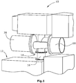
- the vacuum pump system has a first, in particular particle-insensitive, vacuum pump 10, such as a root pump. Furthermore, the vacuum pump system has a second, in particular particle-sensitive, vacuum pump 12, which is, for example, an oil-sealed rotary-displacement pump, a dry-running screw pump and the like. is. Between the two vacuum pumps, a connecting element 14 is arranged. The connecting element 14 is connected to the second vacuum pump via a tubular intermediate element 16 and in the illustrated embodiment directly connected to an outlet of the first vacuum pump 10, so that the connecting element 14 carries the first vacuum pump 10. The connecting element forms flow channels (see FIGS. 2 and 3 ) out. These direct the medium to be conveyed through a filter element, wherein in the illustrated embodiment with the connecting element 14, a coarse filter 18 and a fine filter 20 or two different filter types is connected.
- the inventively constructed connecting element 14 has a first flange-like projection 22 (FIG. Fig. 2 ), which, for example, via screw directly connected to an outlet 24 of the first vacuum pump 10. If appropriate, this can also take place via a particularly rigid, tubular intermediate element. Due to the provision of such flange connections a rigid connection between the flange 22 and the first vacuum pump 10 is realized.
- the connecting element has a second flange-shaped projection 26, which is connected either directly or, as in the illustrated embodiment, via a raw intermediate element 16 indirectly to an inlet 28 of the second vacuum pump 12.
- the connection is preferably carried out by screws.
- the connecting element has rigid wall elements, in particular the central, internal, rigid wall element 30.
- the flow channels forming wall elements 32, 34 can be carried out a transmission of the weight of the first vacuum pump 10 and also occurring during operation forces and moments.
- the connecting element 14 has a curved inlet channel 36 which is connected to the outlet 24 of the first vacuum pump and to the filter element, which in the example shown is the coarse filter 18 is.
- Medium to be delivered is thus pumped by the first vacuum pump 10 through its outlet 24 into the curved inlet channel 36 and from there into an outer region 38 of the coarse filter. From the outer annular cylindrical portion 38 of the coarse filter, the medium is conveyed radially inwardly into an inner cylindrical portion 40 of the coarse filter, wherein the medium in this case flows through the filter material 42 for coarse filtering.
- the medium flows into a connecting channel 44.
- the connecting channel 44 expands in the flow direction in the illustrated embodiment to an annular channel 46, which is then connected to an annular cylindrical portion 48 of the fine filter 20.
- the medium flows from the outer annular cylindrical portion 48 radially inwardly through the filter material 50 in the cylindrical portion 52.
- the cylindrical inner region 52 of the fine filter 20 is connected to the inlet 18 of the second vacuum pump 12 via a curved outlet channel 54 and, in the illustrated embodiment, via the tubular intermediate element 16.
- the curved outlet channel is in this case arranged such that it is separated from the annular channel 46 (FIG. Fig. 2 ) is surrounded in the transition region, so that a compact design is realized.
Landscapes
- Engineering & Computer Science (AREA)
- Mechanical Engineering (AREA)
- General Engineering & Computer Science (AREA)
- Compressors, Vaccum Pumps And Other Relevant Systems (AREA)
- Compressor (AREA)
Claims (14)
- Système de pompe à vide avecune première pompe à vide (10) insensible aux particules,une deuxième pompe à vide (12) sensible aux particules agencée après la première pompe à vide (10) dans la direction du courant, etun élément de raccordement (14) agencé entre les pompes à vide (10, 12), lequel porte la première ou la deuxième pompe à vide (10, 12),caractérisé en ce que :un élément de filtre (18, 20) est agencé entre les pompes à vide (10, 12), lequel est raccordé à l'élément de raccordement (14) etl'élément de raccordement (14) comporte un canal d'admission (36) courbé et raccordé à une évacuation (24) de la première pompe à vide (10) et à l'élément de filtre (18) .
- Système de pompe à vide selon la revendication 1, caractérisé en ce que l'élément de filtre (18, 20) est intégré dans l'élément de raccordement.
- Système de pompe à vide selon la revendication 1 ou 2, caractérisé en ce que l'élément de raccordement (14) comporte un premier appendice (22) pouvant être raccordé de manière rigide à une évacuation (24) de la première pompe à vide (10).
- Système de pompe à vide selon l'une des revendications 1 à 3, caractérisé en ce que l'élément de raccordement (14) comporte un deuxième appendice (26) pouvant être raccordé de manière rigide à une admission (28) de la deuxième pompe à vide (12).
- Système de pompe à vide selon l'une des revendications 1 à 4, caractérisé en ce que l'élément de filtre comporte un filtre grossier (18) et un filtre fin (20).
- Système de pompe à vide selon l'une des revendications 1 à 5, caractérisé en ce que l'élément de filtre, en particulier le filtre grossier (18) et/ou le filtre fin (20), est agencé latéralement sur l'élément de raccordement (14), en particulier de manière amovible.
- Système de pompe à vide selon l'une des revendications 1 à 6, caractérisé en ce que le canal d'admission courbé (36) est agencé entre l'évacuation (24) de la première pompe à vide (10) et le filtre grossier (18).
- Système de pompe à vide selon l'une des revendications 1 à 7, caractérisé en ce que l'élément de raccordement (14) comporte un canal de raccordement (44) agencé entre le filtre grossier (18) et le filtre fin (20).
- Système de pompe à vide selon la revendication 8, caractérisé en ce que le canal de raccordement (44) est raccordé à un canal annulaire (48) entourant l'élément de filtre (50) du filtre fin (20).
- Système de pompe à vide selon l'une des revendications 1 à 9, caractérisé en ce que l'élément de raccordement (14) comporte un deuxième canal d'évacuation (54), de préférence courbé, raccordé à l'évacuation de l'élément de filtre, en particulier du filtre fin (20), et à l'admission (28) de la deuxième pompe à vide (12).
- Système de pompe à vide selon la revendication 10, caractérisé en ce que le canal d'évacuation (54), situé de préférence à l'intérieur, est entouré par le canal de raccordement (44, 46), en particulier dans la zone de transition vers le canal annulaire (48).
- Système de pompe à vide selon l'une des revendications 7 à 11, caractérisé en ce que les parois (30, 32, 34), réalisant le canal d'admission (36) et/ou le canal de raccordement (44, 46) et/ou le canal d'évacuation (54), réalisent l'élément de raccordement (14) rigide portant la première pompe à vide (10).
- Système de pompe à vide selon l'une des revendications 1 à 12, caractérisé en ce que la première pompe à vide (10) et/ou la deuxième pompe à vide (12) est réalisée comme pompe à vide compressant à sec.
- Système de pompe à vide selon l'une des revendications 1 à 13, caractérisée en ce que la deuxième pompe à vide (12) est réalisée comme pompe à palettes.
Applications Claiming Priority (2)
| Application Number | Priority Date | Filing Date | Title |
|---|---|---|---|
| DE202013003819.5U DE202013003819U1 (de) | 2013-04-24 | 2013-04-24 | Vakuumpumpen-System |
| PCT/EP2014/057292 WO2014173692A1 (fr) | 2013-04-24 | 2014-04-10 | Système de pompe à vide |
Publications (2)
| Publication Number | Publication Date |
|---|---|
| EP2989295A1 EP2989295A1 (fr) | 2016-03-02 |
| EP2989295B1 true EP2989295B1 (fr) | 2019-08-28 |
Family
ID=50513901
Family Applications (1)
| Application Number | Title | Priority Date | Filing Date |
|---|---|---|---|
| EP14718365.1A Active EP2989295B1 (fr) | 2013-04-24 | 2014-04-10 | Système de pompe à vide |
Country Status (5)
| Country | Link |
|---|---|
| EP (1) | EP2989295B1 (fr) |
| CN (1) | CN105164375B (fr) |
| DE (1) | DE202013003819U1 (fr) |
| TW (1) | TWI615550B (fr) |
| WO (1) | WO2014173692A1 (fr) |
Family Cites Families (16)
| Publication number | Priority date | Publication date | Assignee | Title |
|---|---|---|---|---|
| GB661522A (en) * | 1949-03-31 | 1951-11-21 | Eureka Williams Corp | Improvements in or relating to oil burners |
| JPS60256584A (ja) * | 1984-05-30 | 1985-12-18 | Honjiyou Chem Kk | 高真空装置 |
| DE8905452U1 (de) * | 1989-04-29 | 1989-08-10 | Leybold AG, Zweigniederlassung Köln, 5000 Köln | Filter für den Einsatz bei Vakuumanlagen |
| DE59010310D1 (de) * | 1990-03-27 | 1996-06-05 | Leybold Ag | Mehrstufige trockenverdichtende Vakuumpumpe und Verfahren zu ihrem Betrieb |
| JPH05113180A (ja) * | 1991-09-05 | 1993-05-07 | Ebara Corp | 真空ポンプの連結装置 |
| NL9200076A (nl) * | 1992-01-16 | 1993-08-16 | Leybold B V | Werkwijze, droge meertrapspomp en plasmascrubber voor het omvormen van reactieve gassen. |
| GB9615859D0 (en) * | 1996-07-29 | 1996-09-11 | Boc Group Plc | Processes and apparatus for the scrubbing of exhaust gas streams |
| SG97943A1 (en) * | 1999-10-04 | 2003-08-20 | Ebara Corp | Vacuum exhaust system |
| US6325932B1 (en) * | 1999-11-30 | 2001-12-04 | Mykrolis Corporation | Apparatus and method for pumping high viscosity fluid |
| JP2004100594A (ja) * | 2002-09-10 | 2004-04-02 | Toyota Industries Corp | 真空ポンプ装置 |
| CN200987786Y (zh) * | 2006-12-29 | 2007-12-12 | 河南核工程空气净化技术有限责任公司 | 箱室进风净化装置 |
| JP2010138725A (ja) * | 2008-12-09 | 2010-06-24 | Toyota Industries Corp | 真空ポンプ装置 |
| DE102009037010A1 (de) * | 2009-08-11 | 2011-02-17 | Oerlikon Leybold Vacuum Gmbh | Vakuumpumpensystem |
| GB2475254B (en) * | 2009-11-11 | 2016-02-10 | Edwards Ltd | Vacuum pump |
| GB201005273D0 (en) * | 2010-03-30 | 2010-05-12 | Edwards Ltd | Scroll compressor |
| JP5353838B2 (ja) * | 2010-07-07 | 2013-11-27 | 株式会社島津製作所 | 真空ポンプ |
-
2013
- 2013-04-24 DE DE202013003819.5U patent/DE202013003819U1/de not_active Expired - Lifetime
-
2014
- 2014-04-10 WO PCT/EP2014/057292 patent/WO2014173692A1/fr not_active Ceased
- 2014-04-10 CN CN201480023355.0A patent/CN105164375B/zh not_active Expired - Fee Related
- 2014-04-10 EP EP14718365.1A patent/EP2989295B1/fr active Active
- 2014-04-21 TW TW103114377A patent/TWI615550B/zh not_active IP Right Cessation
Non-Patent Citations (1)
| Title |
|---|
| None * |
Also Published As
| Publication number | Publication date |
|---|---|
| CN105164375A (zh) | 2015-12-16 |
| TWI615550B (zh) | 2018-02-21 |
| TW201502379A (zh) | 2015-01-16 |
| WO2014173692A1 (fr) | 2014-10-30 |
| CN105164375B (zh) | 2018-10-16 |
| DE202013003819U1 (de) | 2014-07-25 |
| EP2989295A1 (fr) | 2016-03-02 |
Similar Documents
| Publication | Publication Date | Title |
|---|---|---|
| EP2938418B1 (fr) | Séparateur à vis de pression | |
| DE10122675B4 (de) | Strangpressvorrichtung für Keramikformprodukte | |
| EP2329082B1 (fr) | Dispositif de levage d'eaux usee | |
| EP3932515B1 (fr) | Filtre à disque rotatif | |
| EP2433692A1 (fr) | Dispositif pour le tamisage et l'enlèvement de matière à partir d'un liquide coulant dans un canal | |
| EP3519699B1 (fr) | Arrangement de pompage | |
| EP1509308B1 (fr) | Dispositif de filtration de fluides achemines sous haute pression | |
| EP3000518A1 (fr) | Dispositif de filtre a eau equipe d'un filtre a eau a lavage a contrecourant a vitesse reduite d'ecoulement et procede de lavage a contrecourant d'un filtre a eau | |
| EP2989295B1 (fr) | Système de pompe à vide | |
| EP2660473A1 (fr) | Pompe à eaux usées | |
| EP3767105B1 (fr) | Stator pour une pompe à vis sans fin excentrique | |
| DE102016108441B4 (de) | Verfahren und Vorrichtung zur Separation eines Stoffgemischs | |
| EP2801672B1 (fr) | Séparateur de système | |
| DE112018002689B4 (de) | Filteranordnung und Verfahren zum Herstellen einer Filteranordnung | |
| EP2481474B1 (fr) | Agencement d'étanchéité pour éléments de filtre céramique en forme de tiges | |
| WO1994007072A1 (fr) | Raccord de tuyaux demontable | |
| WO2009039881A1 (fr) | Pompe à engrenages avec carter de pompe en plusieurs parties | |
| EP3105045B1 (fr) | Séparateur à vis de pression | |
| WO2016124410A1 (fr) | Vis de gavage | |
| EP3620318B1 (fr) | Dispositif de soupape hydraulique | |
| EP4620552A1 (fr) | Élément filtrant, élément filtrant échangeur d'ions et système de filtration | |
| DE102024113571A1 (de) | Wechselventileinsatz und Wechselventil, das einen Einsatz aufweist | |
| DE102023123608A1 (de) | Schneckenextruder zur Granulatverarbeitung | |
| EP4345352A1 (fr) | Connecteur médical avec joint radial à faible espace mort | |
| DE102015215595A1 (de) | Steckelement und Milchaufschäumeinrichtung |
Legal Events
| Date | Code | Title | Description |
|---|---|---|---|
| PUAI | Public reference made under article 153(3) epc to a published international application that has entered the european phase |
Free format text: ORIGINAL CODE: 0009012 |
|
| 17P | Request for examination filed |
Effective date: 20151021 |
|
| AK | Designated contracting states |
Kind code of ref document: A1 Designated state(s): AL AT BE BG CH CY CZ DE DK EE ES FI FR GB GR HR HU IE IS IT LI LT LU LV MC MK MT NL NO PL PT RO RS SE SI SK SM TR |
|
| AX | Request for extension of the european patent |
Extension state: BA ME |
|
| DAX | Request for extension of the european patent (deleted) | ||
| RAP1 | Party data changed (applicant data changed or rights of an application transferred) |
Owner name: LEYBOLD GMBH |
|
| GRAP | Despatch of communication of intention to grant a patent |
Free format text: ORIGINAL CODE: EPIDOSNIGR1 |
|
| STAA | Information on the status of an ep patent application or granted ep patent |
Free format text: STATUS: GRANT OF PATENT IS INTENDED |
|
| INTG | Intention to grant announced |
Effective date: 20190312 |
|
| GRAS | Grant fee paid |
Free format text: ORIGINAL CODE: EPIDOSNIGR3 |
|
| GRAA | (expected) grant |
Free format text: ORIGINAL CODE: 0009210 |
|
| STAA | Information on the status of an ep patent application or granted ep patent |
Free format text: STATUS: THE PATENT HAS BEEN GRANTED |
|
| AK | Designated contracting states |
Kind code of ref document: B1 Designated state(s): AL AT BE BG CH CY CZ DE DK EE ES FI FR GB GR HR HU IE IS IT LI LT LU LV MC MK MT NL NO PL PT RO RS SE SI SK SM TR |
|
| REG | Reference to a national code |
Ref country code: GB Ref legal event code: FG4D Free format text: NOT ENGLISH |
|
| REG | Reference to a national code |
Ref country code: CH Ref legal event code: EP |
|
| REG | Reference to a national code |
Ref country code: AT Ref legal event code: REF Ref document number: 1172637 Country of ref document: AT Kind code of ref document: T Effective date: 20190915 |
|
| REG | Reference to a national code |
Ref country code: IE Ref legal event code: FG4D Free format text: LANGUAGE OF EP DOCUMENT: GERMAN |
|
| REG | Reference to a national code |
Ref country code: DE Ref legal event code: R096 Ref document number: 502014012511 Country of ref document: DE |
|
| REG | Reference to a national code |
Ref country code: CH Ref legal event code: NV Representative=s name: ISLER AND PEDRAZZINI AG, CH |
|
| REG | Reference to a national code |
Ref country code: NL Ref legal event code: MP Effective date: 20190828 |
|
| REG | Reference to a national code |
Ref country code: LT Ref legal event code: MG4D |
|
| PG25 | Lapsed in a contracting state [announced via postgrant information from national office to epo] |
Ref country code: SE Free format text: LAPSE BECAUSE OF FAILURE TO SUBMIT A TRANSLATION OF THE DESCRIPTION OR TO PAY THE FEE WITHIN THE PRESCRIBED TIME-LIMIT Effective date: 20190828 Ref country code: HR Free format text: LAPSE BECAUSE OF FAILURE TO SUBMIT A TRANSLATION OF THE DESCRIPTION OR TO PAY THE FEE WITHIN THE PRESCRIBED TIME-LIMIT Effective date: 20190828 Ref country code: PT Free format text: LAPSE BECAUSE OF FAILURE TO SUBMIT A TRANSLATION OF THE DESCRIPTION OR TO PAY THE FEE WITHIN THE PRESCRIBED TIME-LIMIT Effective date: 20191230 Ref country code: LT Free format text: LAPSE BECAUSE OF FAILURE TO SUBMIT A TRANSLATION OF THE DESCRIPTION OR TO PAY THE FEE WITHIN THE PRESCRIBED TIME-LIMIT Effective date: 20190828 Ref country code: FI Free format text: LAPSE BECAUSE OF FAILURE TO SUBMIT A TRANSLATION OF THE DESCRIPTION OR TO PAY THE FEE WITHIN THE PRESCRIBED TIME-LIMIT Effective date: 20190828 Ref country code: NL Free format text: LAPSE BECAUSE OF FAILURE TO SUBMIT A TRANSLATION OF THE DESCRIPTION OR TO PAY THE FEE WITHIN THE PRESCRIBED TIME-LIMIT Effective date: 20190828 Ref country code: BG Free format text: LAPSE BECAUSE OF FAILURE TO SUBMIT A TRANSLATION OF THE DESCRIPTION OR TO PAY THE FEE WITHIN THE PRESCRIBED TIME-LIMIT Effective date: 20191128 Ref country code: NO Free format text: LAPSE BECAUSE OF FAILURE TO SUBMIT A TRANSLATION OF THE DESCRIPTION OR TO PAY THE FEE WITHIN THE PRESCRIBED TIME-LIMIT Effective date: 20191128 |
|
| PG25 | Lapsed in a contracting state [announced via postgrant information from national office to epo] |
Ref country code: AL Free format text: LAPSE BECAUSE OF FAILURE TO SUBMIT A TRANSLATION OF THE DESCRIPTION OR TO PAY THE FEE WITHIN THE PRESCRIBED TIME-LIMIT Effective date: 20190828 Ref country code: ES Free format text: LAPSE BECAUSE OF FAILURE TO SUBMIT A TRANSLATION OF THE DESCRIPTION OR TO PAY THE FEE WITHIN THE PRESCRIBED TIME-LIMIT Effective date: 20190828 Ref country code: IS Free format text: LAPSE BECAUSE OF FAILURE TO SUBMIT A TRANSLATION OF THE DESCRIPTION OR TO PAY THE FEE WITHIN THE PRESCRIBED TIME-LIMIT Effective date: 20191228 Ref country code: LV Free format text: LAPSE BECAUSE OF FAILURE TO SUBMIT A TRANSLATION OF THE DESCRIPTION OR TO PAY THE FEE WITHIN THE PRESCRIBED TIME-LIMIT Effective date: 20190828 Ref country code: GR Free format text: LAPSE BECAUSE OF FAILURE TO SUBMIT A TRANSLATION OF THE DESCRIPTION OR TO PAY THE FEE WITHIN THE PRESCRIBED TIME-LIMIT Effective date: 20191129 Ref country code: RS Free format text: LAPSE BECAUSE OF FAILURE TO SUBMIT A TRANSLATION OF THE DESCRIPTION OR TO PAY THE FEE WITHIN THE PRESCRIBED TIME-LIMIT Effective date: 20190828 |
|
| PG25 | Lapsed in a contracting state [announced via postgrant information from national office to epo] |
Ref country code: TR Free format text: LAPSE BECAUSE OF FAILURE TO SUBMIT A TRANSLATION OF THE DESCRIPTION OR TO PAY THE FEE WITHIN THE PRESCRIBED TIME-LIMIT Effective date: 20190828 |
|
| PG25 | Lapsed in a contracting state [announced via postgrant information from national office to epo] |
Ref country code: RO Free format text: LAPSE BECAUSE OF FAILURE TO SUBMIT A TRANSLATION OF THE DESCRIPTION OR TO PAY THE FEE WITHIN THE PRESCRIBED TIME-LIMIT Effective date: 20190828 Ref country code: DK Free format text: LAPSE BECAUSE OF FAILURE TO SUBMIT A TRANSLATION OF THE DESCRIPTION OR TO PAY THE FEE WITHIN THE PRESCRIBED TIME-LIMIT Effective date: 20190828 Ref country code: EE Free format text: LAPSE BECAUSE OF FAILURE TO SUBMIT A TRANSLATION OF THE DESCRIPTION OR TO PAY THE FEE WITHIN THE PRESCRIBED TIME-LIMIT Effective date: 20190828 Ref country code: PL Free format text: LAPSE BECAUSE OF FAILURE TO SUBMIT A TRANSLATION OF THE DESCRIPTION OR TO PAY THE FEE WITHIN THE PRESCRIBED TIME-LIMIT Effective date: 20190828 |
|
| PG25 | Lapsed in a contracting state [announced via postgrant information from national office to epo] |
Ref country code: IS Free format text: LAPSE BECAUSE OF FAILURE TO SUBMIT A TRANSLATION OF THE DESCRIPTION OR TO PAY THE FEE WITHIN THE PRESCRIBED TIME-LIMIT Effective date: 20200224 Ref country code: SK Free format text: LAPSE BECAUSE OF FAILURE TO SUBMIT A TRANSLATION OF THE DESCRIPTION OR TO PAY THE FEE WITHIN THE PRESCRIBED TIME-LIMIT Effective date: 20190828 Ref country code: SM Free format text: LAPSE BECAUSE OF FAILURE TO SUBMIT A TRANSLATION OF THE DESCRIPTION OR TO PAY THE FEE WITHIN THE PRESCRIBED TIME-LIMIT Effective date: 20190828 Ref country code: CZ Free format text: LAPSE BECAUSE OF FAILURE TO SUBMIT A TRANSLATION OF THE DESCRIPTION OR TO PAY THE FEE WITHIN THE PRESCRIBED TIME-LIMIT Effective date: 20190828 |
|
| REG | Reference to a national code |
Ref country code: DE Ref legal event code: R097 Ref document number: 502014012511 Country of ref document: DE |
|
| PLBE | No opposition filed within time limit |
Free format text: ORIGINAL CODE: 0009261 |
|
| STAA | Information on the status of an ep patent application or granted ep patent |
Free format text: STATUS: NO OPPOSITION FILED WITHIN TIME LIMIT |
|
| PG2D | Information on lapse in contracting state deleted |
Ref country code: IS |
|
| 26N | No opposition filed |
Effective date: 20200603 |
|
| PG25 | Lapsed in a contracting state [announced via postgrant information from national office to epo] |
Ref country code: SI Free format text: LAPSE BECAUSE OF FAILURE TO SUBMIT A TRANSLATION OF THE DESCRIPTION OR TO PAY THE FEE WITHIN THE PRESCRIBED TIME-LIMIT Effective date: 20190828 |
|
| PG25 | Lapsed in a contracting state [announced via postgrant information from national office to epo] |
Ref country code: MC Free format text: LAPSE BECAUSE OF FAILURE TO SUBMIT A TRANSLATION OF THE DESCRIPTION OR TO PAY THE FEE WITHIN THE PRESCRIBED TIME-LIMIT Effective date: 20190828 |
|
| PG25 | Lapsed in a contracting state [announced via postgrant information from national office to epo] |
Ref country code: LU Free format text: LAPSE BECAUSE OF NON-PAYMENT OF DUE FEES Effective date: 20200410 |
|
| REG | Reference to a national code |
Ref country code: BE Ref legal event code: MM Effective date: 20200430 |
|
| PG25 | Lapsed in a contracting state [announced via postgrant information from national office to epo] |
Ref country code: BE Free format text: LAPSE BECAUSE OF NON-PAYMENT OF DUE FEES Effective date: 20200430 |
|
| PG25 | Lapsed in a contracting state [announced via postgrant information from national office to epo] |
Ref country code: IE Free format text: LAPSE BECAUSE OF NON-PAYMENT OF DUE FEES Effective date: 20200410 |
|
| REG | Reference to a national code |
Ref country code: AT Ref legal event code: MM01 Ref document number: 1172637 Country of ref document: AT Kind code of ref document: T Effective date: 20200410 |
|
| PG25 | Lapsed in a contracting state [announced via postgrant information from national office to epo] |
Ref country code: AT Free format text: LAPSE BECAUSE OF NON-PAYMENT OF DUE FEES Effective date: 20200410 |
|
| PG25 | Lapsed in a contracting state [announced via postgrant information from national office to epo] |
Ref country code: MT Free format text: LAPSE BECAUSE OF FAILURE TO SUBMIT A TRANSLATION OF THE DESCRIPTION OR TO PAY THE FEE WITHIN THE PRESCRIBED TIME-LIMIT Effective date: 20190828 Ref country code: CY Free format text: LAPSE BECAUSE OF FAILURE TO SUBMIT A TRANSLATION OF THE DESCRIPTION OR TO PAY THE FEE WITHIN THE PRESCRIBED TIME-LIMIT Effective date: 20190828 |
|
| PG25 | Lapsed in a contracting state [announced via postgrant information from national office to epo] |
Ref country code: MK Free format text: LAPSE BECAUSE OF FAILURE TO SUBMIT A TRANSLATION OF THE DESCRIPTION OR TO PAY THE FEE WITHIN THE PRESCRIBED TIME-LIMIT Effective date: 20190828 |
|
| P01 | Opt-out of the competence of the unified patent court (upc) registered |
Effective date: 20230423 |
|
| PGFP | Annual fee paid to national office [announced via postgrant information from national office to epo] |
Ref country code: IT Payment date: 20230428 Year of fee payment: 10 Ref country code: FR Payment date: 20230417 Year of fee payment: 10 Ref country code: DE Payment date: 20230426 Year of fee payment: 10 Ref country code: CH Payment date: 20230502 Year of fee payment: 10 |
|
| PGFP | Annual fee paid to national office [announced via postgrant information from national office to epo] |
Ref country code: GB Payment date: 20230420 Year of fee payment: 10 |
|
| REG | Reference to a national code |
Ref country code: DE Ref legal event code: R119 Ref document number: 502014012511 Country of ref document: DE |
|
| REG | Reference to a national code |
Ref country code: CH Ref legal event code: PL |
|
| GBPC | Gb: european patent ceased through non-payment of renewal fee |
Effective date: 20240410 |
|
| PG25 | Lapsed in a contracting state [announced via postgrant information from national office to epo] |
Ref country code: DE Free format text: LAPSE BECAUSE OF NON-PAYMENT OF DUE FEES Effective date: 20241105 |
|
| PG25 | Lapsed in a contracting state [announced via postgrant information from national office to epo] |
Ref country code: GB Free format text: LAPSE BECAUSE OF NON-PAYMENT OF DUE FEES Effective date: 20240410 |
|
| PG25 | Lapsed in a contracting state [announced via postgrant information from national office to epo] |
Ref country code: FR Free format text: LAPSE BECAUSE OF NON-PAYMENT OF DUE FEES Effective date: 20240430 |
|
| PG25 | Lapsed in a contracting state [announced via postgrant information from national office to epo] |
Ref country code: GB Free format text: LAPSE BECAUSE OF NON-PAYMENT OF DUE FEES Effective date: 20240410 Ref country code: FR Free format text: LAPSE BECAUSE OF NON-PAYMENT OF DUE FEES Effective date: 20240430 Ref country code: DE Free format text: LAPSE BECAUSE OF NON-PAYMENT OF DUE FEES Effective date: 20241105 Ref country code: CH Free format text: LAPSE BECAUSE OF NON-PAYMENT OF DUE FEES Effective date: 20240430 |
|
| PG25 | Lapsed in a contracting state [announced via postgrant information from national office to epo] |
Ref country code: IT Free format text: LAPSE BECAUSE OF NON-PAYMENT OF DUE FEES Effective date: 20240410 |