EP3019645B1 - Dispositif de filage de fils - Google Patents
Dispositif de filage de fils Download PDFInfo
- Publication number
- EP3019645B1 EP3019645B1 EP14711745.1A EP14711745A EP3019645B1 EP 3019645 B1 EP3019645 B1 EP 3019645B1 EP 14711745 A EP14711745 A EP 14711745A EP 3019645 B1 EP3019645 B1 EP 3019645B1
- Authority
- EP
- European Patent Office
- Prior art keywords
- housing
- heating chamber
- housing wall
- heating
- condensate
- Prior art date
- Legal status (The legal status is an assumption and is not a legal conclusion. Google has not performed a legal analysis and makes no representation as to the accuracy of the status listed.)
- Not-in-force
Links
Images


Classifications
-
- D—TEXTILES; PAPER
- D01—NATURAL OR MAN-MADE THREADS OR FIBRES; SPINNING
- D01D—MECHANICAL METHODS OR APPARATUS IN THE MANUFACTURE OF ARTIFICIAL FILAMENTS, THREADS, FIBRES, BRISTLES OR RIBBONS
- D01D1/00—Treatment of filament-forming or like material
- D01D1/06—Feeding liquid to the spinning head
- D01D1/09—Control of pressure, temperature or feeding rate
Definitions
- the invention relates to a device for spinning threads according to the preamble of claim 1 and a method for heating a device for spinning threads according to the preamble of claim 13.
- Devices for spinning threads, which have at least one melt feed device and at least one nozzle package with at least one spinneret for spinning the threads.
- the nozzle package and thus the spinneret are heated.
- EP0828017 and WO2008 / 101863 It is known that a first housing with a first housing wall is arranged around the nozzle package.
- a second housing with a second housing wall can be arranged around the first housing.
- Between the first and the second housing a filled with a gaseous heating medium heating chamber is arranged, wherein the first and the second housing wall define the boiler room. In this way, the nozzle package and thus the spinneret can be heated.
- melt spinning apparatus for melt spinning synthetic filaments having a plurality of spin packs substantially circular about a center.
- the melt spinning device heated by means of a heat transfer medium has a depression in which condensed heat transfer medium collects and is vaporized again by means of a heater.
- a spinneret for melt-spinning filaments is known in which the heat transfer from the heating box of a spinner to the nozzle package carried therein is improved by providing the package support with heat-absorbing elements. These elements are exposed to saturated steam during operation and are provided with condensation flocks to absorb heat from the saturated steam. The heat absorbed is transferred to the package via at least one thermal bridge.
- Another spinning beam is out of the EP0163248 known, in which the heating jacket of the spinner is housed in a housing and surrounded by a thermal insulation.
- the present invention is therefore based on the object to provide an apparatus and a method in which or in which the nozzle package and thus the spinneret can be heated uniformly.
- the invention advantageously provides that the heating space is delimited by a housing bottom, which is formed sloping obliquely from the first housing wall in the direction of the second housing wall, so that condensate accumulated on the housing bottom expires in the direction of the second housing wall.
- the first housing wall can be connected to the second housing wall via a floor element having the housing bottom.
- An outlet opening can be provided in the second housing wall, to which a condensate discharge line is connected, wherein the condensate accumulating in the heating space and accumulated on the housing bottom can be conducted to the outlet opening due to the contour of the housing bottom.
- the outlet opening may be arranged such that at least a part of the outlet opening is deeper than the lowest point of the housing bottom. In this way, the condensate can be removed particularly effectively and quickly.
- At least the lowest point of the housing bottom near the second housing wall can be arranged lower than the bottom of the nozzle package arranged in the first housing.
- the highest point of the housing bottom near the first housing wall can be arranged lower than the bottom of the nozzle package arranged in the first housing.
- the first and the second housing may be cylindrical, in particular circular cylindrical, formed. This means that the heat loss to the outside is particularly low. In this way energy can be saved for heating. Furthermore, it is easier to keep the temperature constant.
- the first housing surrounded by the heating chamber has a housing cover, which has a circumferential groove.
- the melt supply device can have a metering device, wherein the metering device is arranged within the heating chamber.
- the metering device is preferably arranged above the first housing.
- the gaseous heating medium can be fed to the boiler room via a Walkerzugenesis effet.
- the Schuther may have a second Kondensatabschreib Kunststoff. In this way it is prevented that the condensate that forms in the Walkerzumoltechnisch is introduced into the boiler room.
- the second Kondensatabschreib may be arranged near the entrance of the first Schuzuthetechnisch in the boiler room.
- the first housing may be downwardly open so that the nozzle package is insertable into the first housing.
- the condensate can be directed into the Kondensatabschreib für
- Fig. 1 schematically shows a device 1 for spinning threads.
- Melt is melted in a melting device 2 and fed via a melt feed line 20 to a metering device 12. From there, the melt is pressed through a spinneret arranged in a nozzle package 4 and withdrawn in the form of filaments or fibers 35. After exiting the spinneret, the filaments are in an injection shaft 27 by means of eg air cooled and the cooled fibers 33 can then be wound on drums or stored in cans. The filaments can be drawn directly or later in drawing devices, not shown.
- the melting device 2, the melt supply line 20 and the metering device 12 are part of a melt feed device.
- a nozzle package is a holder for a spinneret.
- a part of the device 1 for spinning threads is shown in more detail.
- the melting device 2 is not shown and also the injection shaft 27 is not shown.
- the nozzle package 4 with at least one spinneret is arranged in a first housing 8.
- the nozzle package 4 is shown only schematically. Only the outer boundary of the nozzle package is shown in order to illustrate where the nozzle package 4 is arranged.
- a second housing 10 is arranged, wherein between the first and the second housing 8, 10 a filled with a gaseous heating medium heating chamber 14 is arranged.
- the second housing 10 has a second housing wall 6 and a housing cover 29 arranged at the upper end of the second housing wall 6.
- the first housing 8 arranged in the second housing 10 has a first housing wall 3 and a housing cover 16 arranged at the upper end of the first housing wall 3.
- the upper end opposite lower end of the first housing wall 3 is connected to the upper end opposite the lower end of the second housing wall 6 via a housing bottom 28 having Bodenelement 25.
- the housing bottom 28 is the housing bottom 28 of the heating chamber 14 and limits it down.
- the housing bottom 28 is the heating chamber 14 facing side of the bottom element 25.
- the first housing 8 is open at the bottom, so that the nozzle package 4 is inserted into the first housing.
- the metering device 12 is arranged above the first housing 8. Between metering device 12 and arranged in the first housing 8 nozzle package 4, a melt line 26 is arranged to guide the melt from the metering device 12 to the nozzle package 4. Both the Metering device 12 and the first housing 8 are at least partially surrounded by the heating chamber 14 and can thus be heated by the arranged in the heating chamber 14 gaseous heating medium.
- the melt is now guided by the melting device 2 via the melt supply line 20 to the metering device 12.
- the melt supply line 20 is arranged outside the heating chamber 14 in a Walkerzu900 glaci 22. In this way, the melt supply line 20 is heated.
- the Edelzu900technisch 22 leads the gaseous heating medium to the heating chamber 14.
- a melt holding device 24 is arranged, which can reduce the cross section of the melt supply line 20 by pressure build-up and thus can interrupt the supply of the melt to the metering device 12 at least temporarily.
- the first housing 8 and / or the second housing 10 are preferably circular cylindrical. This has the advantage that it comes to lower heat losses. In this way energy can be saved.
- the first housing 8 and / or the second housing 10 may alternatively have a different shape. They can for example also be cuboid. In this case, the first housing would have four first housing walls and the second housing would have four second housing walls.
- a sleeve 70 for the connection of a temperature sensor is daong.
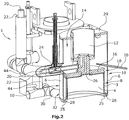
- the housing bottom 28, the in Fig. 3 is shown in detail, is formed sloping from the first housing wall in the direction of the second housing wall 6, so that a condensate accumulated on the housing bottom 28 in the direction of the second housing wall 6 expires.
- the condensate that forms in the heating chamber 14 accumulates at the housing bottom 28. Due to the contour of the housing bottom 28, the condensate, however, runs in the direction of the second housing wall 6. In this way, the condensate does not accumulate on the first housing wall 3. This has the advantage that the temperature can be kept constant, in particular in the nozzle package 4.
- an outlet opening 32 is arranged on the second housing wall 6, an outlet opening 32 is arranged.
- a Kondensatab2020 Gustav 30 is connected.
- the accumulated in the boiler room and accumulated at the bottom of the housing condensate can be passed to the outlet opening 32 due to the contour of the housing bottom 28 and discharged there through the Kondensatab2020 Gustav 30.
- the Kondensatabfueltechnisch 30 is preferably arranged such that at least a portion of the Kondensatabfueltechnisch 30 is deeper than the lowest point 40 of the housing bottom 28th
- the lowest point 40 of the housing bottom 28 is disposed near the second housing wall 6.
- the lowest point 40 of the housing bottom 28 is arranged lower than the bottom 42 of the nozzle package 4 arranged in the first housing 8. This has the advantage that the condensate does not accumulate in the region in which the nozzle package 4 is arranged. Thus, the nozzle package 4 can be heated evenly.
- the nozzle package 4 is shown only schematically. Only the outer boundary of the nozzle package is shown in order to illustrate where the nozzle package 4 is arranged.
- a second Kondensatabschreib conspiracy 44 is shown.
- the second Kondensatabfueltechnisch 44 is connected to the Bankzuschreibtechnisch 22.
- the second Kondensatabschreibschreib 44 may be connected near the entrance of the Bankzuschreibtechnisch 22 in the heating chamber 14 with the Schuzuthetechnisch 22.
- the accumulated in the Schuzumoltechnisch 22 condensate can be removed. In this way, the condensate that already forms in the Schuzumoltechnisch 22, not introduced into the heating chamber 14. This ensures that the condensate which forms in the Bankzumoltechnisch is discharged before introduction into the heating chamber 14.
- FIG. 4 the housing cover 16 of the first housing 8 is shown in more detail.
- the housing cover 16 has a circumferential groove 18. By the circumferential groove 18, the heat transfer surface is increased and thus improves the heating of the first housing, in particular in the region of the housing cover 16.
Landscapes
- Engineering & Computer Science (AREA)
- Mechanical Engineering (AREA)
- Textile Engineering (AREA)
- Spinning Methods And Devices For Manufacturing Artificial Fibers (AREA)
- Beans For Foods Or Fodder (AREA)
Claims (14)
- Dispositif (1) destiné au filage de fils, comprenant- au moins un système d'acheminement de matière en fusion,- au moins un bloc de buses (4) avec au moins une filière, au moins un premier boîtier (8) avec au moins une première paroi de boîtier (3) étant disposé autour du bloc de buses (4),- au moins un deuxième boîtier (10) disposé autour du premier boîtier (8) avec au moins une deuxième paroi de boîtier (6), un espace chauffant (14) rempli d'un fluide chauffant gazeux étant disposé entre le premier et le deuxième boîtier (8, 10), l'au moins une première paroi de boîtier (3) et l'au moins une deuxième paroi de boîtier (6) limitant l'espace chauffant (14),caractérisé en ce que
l'espace chauffant (14) est limité par au moins un fond de boîtier (28) qui est réalisé en descendant obliquement à partir de la première paroi de boîtier (3) en direction de la deuxième paroi de boîtier (6) de telle sorte que le condensat collecté sur le fond de boîtier (28) s'écoule en direction de la deuxième paroi de boîtier (6). - Dispositif (1) selon la revendication 1, caractérisé en ce qu'une ouverture de sortie (32) est prévue dans la deuxième paroi de boîtier (6), à laquelle est raccordée une conduite d'évacuation du condensat (30), le condensat présent dans l'espace chauffant (14) et collecté sur le fond de boîtier (28) pouvant être guidé vers l'ouverture de sortie (32) du fait du contour du fond de boîtier (28) qui est réalisé en descendant obliquement à partir de la première paroi de boîtier (3) en direction de la deuxième paroi de boîtier (6).
- Dispositif (1) selon la revendication 2, caractérisé en ce que la conduite d'évacuation du condensat (30) est disposée de telle sorte qu'au moins une partie de la conduite d'évacuation du condensat (30) est plus basse que l'emplacement le plus bas (40) du fond de boîtier (28) .
- Dispositif (1) selon l'une des revendications 1 à 3, caractérisé en ce qu'au moins l'emplacement le plus bas (40) du fond de boîtier (28) est disposé près de la deuxième paroi de boîtier (6) plus bas que le fond (42) du bloc de buses (4) disposé dans le premier boîtier (8).
- Dispositif (1) selon l'une des revendications 1 à 4, caractérisé en ce que le premier et le deuxième boîtier (8, 10) sont réalisés en forme de cylindre, en particulier en forme de cylindre circulaire.
- Dispositif (1) selon l'une des revendications 1 à 5, caractérisé en ce que le premier boîtier (8) présente un premier couvercle de boîtier (16) entouré par l'espace chauffant (14), le premier couvercle de boîtier (16) présentant une rainure (18) périphérique.
- Dispositif (1) selon l'une des revendications 1 à 6, caractérisé en ce que le système d'acheminement de matière en fusion présente un appareil de dosage (12) disposé à l'intérieur de l'espace chauffant (14).
- Dispositif (1) selon l'une des revendications 1 à 7, caractérisé en ce que le fluide chauffant gazeux peut être acheminé à l'espace chauffant (14) par le biais d'une conduite d'acheminement de chauffage (22).
- Dispositif (1) selon la revendication 8, caractérisé en ce que, à l'intérieur de la conduite d'acheminement de chauffage (22), il est disposé une conduite d'acheminement de matière en fusion (20) qui achemine la matière en fusion vers l'appareil de dosage (12).
- Dispositif (1) selon la revendication 8 ou 9, caractérisé en ce que la conduite d'acheminement de chauffage (22) présente une deuxième conduite d'évacuation du condensat (44).
- Dispositif (1) selon la revendication 10, caractérisé en ce que la deuxième conduite d'évacuation du condensat (44) est disposée près de l'entrée de la conduite d'acheminement de chauffage (22) dans l'espace chauffant (14) .
- Dispositif (1) selon l'une des revendications 1 à 11, caractérisé en ce que le premier boîtier (8) est ouvert vers le bas de telle sorte que le bloc de buses (4) peut être introduit dans le premier boîtier (8).
- Procédé destiné au chauffage d'un dispositif (1) selon l'une des revendications 1 à 12 destiné au filage de fils par- l'introduction d'un fluide de chauffage dans un espace chauffant (14) limité par au moins une première et une deuxième paroi de boîtier (3, 6) et par un fond de boîtier (28),- un appareil de dosage (12) à chauffer et un bloc de buses (4) à chauffer avec au moins une filière étant disposés à l'intérieur de l'espace chauffant (14), caractérisé en ce quele condensat présent dans l'espace chauffant (14) est évacué dans la zone du fond de boîtier (28).
- Procédé selon la revendication 13, caractérisé en ce que, du fait du contour du fond de boîtier (28) qui est réalisé en descendant obliquement à partir de la première paroi de boîtier (3) en direction de la deuxième paroi de boîtier (6), le condensat est guidé dans une conduite d'évacuation du condensat (30).
Applications Claiming Priority (2)
| Application Number | Priority Date | Filing Date | Title |
|---|---|---|---|
| DE102013213341.3A DE102013213341A1 (de) | 2013-07-08 | 2013-07-08 | Vorrichtung zum spinnen von fäden |
| PCT/EP2014/055578 WO2015003823A1 (fr) | 2013-07-08 | 2014-03-20 | Dispositif de filage de fils |
Publications (2)
| Publication Number | Publication Date |
|---|---|
| EP3019645A1 EP3019645A1 (fr) | 2016-05-18 |
| EP3019645B1 true EP3019645B1 (fr) | 2017-11-22 |
Family
ID=50343773
Family Applications (1)
| Application Number | Title | Priority Date | Filing Date |
|---|---|---|---|
| EP14711745.1A Not-in-force EP3019645B1 (fr) | 2013-07-08 | 2014-03-20 | Dispositif de filage de fils |
Country Status (5)
| Country | Link |
|---|---|
| EP (1) | EP3019645B1 (fr) |
| CN (1) | CN105378161B (fr) |
| DE (1) | DE102013213341A1 (fr) |
| TW (1) | TW201512473A (fr) |
| WO (1) | WO2015003823A1 (fr) |
Family Cites Families (7)
| Publication number | Priority date | Publication date | Assignee | Title |
|---|---|---|---|---|
| DE3575313D1 (de) * | 1984-05-26 | 1990-02-15 | Barmag Barmer Maschf | Spinnbalken zum schmelzspinnen synthetischer faeden. |
| DE4325580C2 (de) * | 1993-07-30 | 2002-07-18 | Zimmer Ag | Spinnbalken-Pumpenblock |
| DE9313586U1 (de) * | 1993-09-08 | 1993-11-04 | Synthetik Fiber Machinery, 63762 Großostheim | Spinnbalken |
| US5601856A (en) * | 1993-09-08 | 1997-02-11 | Rieter Automatik Gmbh | Spinning beam |
| EP0828017B1 (fr) * | 1996-09-04 | 2001-11-28 | B a r m a g AG | Bloc de filage |
| DE102007021433A1 (de) * | 2006-05-20 | 2007-11-22 | Saurer Gmbh & Co. Kg | Schmelzspinnvorrichtung |
| ATE489491T1 (de) * | 2007-02-24 | 2010-12-15 | Oerlikon Textile Gmbh & Co Kg | Vorrichtung zum schmelzspinnen synthetischer filamente |
-
2013
- 2013-07-08 DE DE102013213341.3A patent/DE102013213341A1/de not_active Withdrawn
-
2014
- 2014-03-20 WO PCT/EP2014/055578 patent/WO2015003823A1/fr not_active Ceased
- 2014-03-20 EP EP14711745.1A patent/EP3019645B1/fr not_active Not-in-force
- 2014-03-20 CN CN201480039212.9A patent/CN105378161B/zh not_active Expired - Fee Related
- 2014-07-03 TW TW103122943A patent/TW201512473A/zh unknown
Also Published As
| Publication number | Publication date |
|---|---|
| CN105378161A (zh) | 2016-03-02 |
| TW201512473A (zh) | 2015-04-01 |
| WO2015003823A1 (fr) | 2015-01-15 |
| CN105378161B (zh) | 2017-09-26 |
| DE102013213341A1 (de) | 2015-01-08 |
| EP3019645A1 (fr) | 2016-05-18 |
Similar Documents
| Publication | Publication Date | Title |
|---|---|---|
| WO2013064588A1 (fr) | Dispositif de filage à chaud et de refroidissement de filaments synthétiques | |
| DE102010019910A1 (de) | Spinndüse zum Spinnen von Fäden, Spinnvorrichtung zum Spinnen von Fäden und Verfahren zum Spinnen von Fäden | |
| EP0748397B1 (fr) | Collecteur-repartiteur | |
| EP1280946B1 (fr) | Procede et dispositif pour acheminer sans traction des corps moules continus | |
| EP0828017B1 (fr) | Bloc de filage | |
| DE102013225252B4 (de) | Garnaufwickelvorrichtung | |
| EP3519617B1 (fr) | Procede et disppositif pour refroidir un fil artificiel | |
| DE1760377B2 (de) | Verfahren und vorrichtung zum trockenspinnen von faserbildenden polymeren | |
| WO2016050897A1 (fr) | Dispositif de filage à l'état fondu | |
| EP2148948B1 (fr) | Dispositif de tirage et d'étirage de fils multifilaments | |
| EP1215022B1 (fr) | Procédé pour la fabrication d'un matériau à base de fibres continues et de matière plastique | |
| EP3312321B1 (fr) | Dispositif pour refroidir les fils | |
| DE102013014572A1 (de) | Vorrichtung zum Schmelzspinnen und Abkühlen synthetischer Filamente | |
| EP3523469B1 (fr) | Dispostif pour refroidir un fil chaud | |
| EP3312322B1 (fr) | Dispositif de refroidissement d'un fil chauffé | |
| WO2015003823A1 (fr) | Dispositif de filage de fils | |
| DE1660224A1 (de) | Verfahren und Vorrichtung zur Waermebehandlung von synthetischen Faeden und fadenartigen Gebilden | |
| DE102013213344A1 (de) | Vorrichtung zum spinnen von fäden | |
| EP3148910B1 (fr) | Dispositif de va-et-vient pour un metier a filer et metier a filer avec un tel dispositif | |
| DE102019120827A1 (de) | Galette | |
| EP3029403B1 (fr) | Procédé et dispositif de séchage de l'isolation de matière solide de la pièce active d'un appareil électrique selon le procédé de phase gazeuse | |
| DE102007021433A1 (de) | Schmelzspinnvorrichtung | |
| DE19920682A1 (de) | Dampfbeschleierung für Spinnsystem mit Rechteckdüsen | |
| DE19809495A1 (de) | Verfahren und Vorrichtung zum Spinnen von Fäden | |
| DE102020005654A1 (de) | Vorrichtung zum Schmelzspinnen von Fäden |
Legal Events
| Date | Code | Title | Description |
|---|---|---|---|
| PUAI | Public reference made under article 153(3) epc to a published international application that has entered the european phase |
Free format text: ORIGINAL CODE: 0009012 |
|
| 17P | Request for examination filed |
Effective date: 20160107 |
|
| AK | Designated contracting states |
Kind code of ref document: A1 Designated state(s): AL AT BE BG CH CY CZ DE DK EE ES FI FR GB GR HR HU IE IS IT LI LT LU LV MC MK MT NL NO PL PT RO RS SE SI SK SM TR |
|
| AX | Request for extension of the european patent |
Extension state: BA ME |
|
| RAP1 | Party data changed (applicant data changed or rights of an application transferred) |
Owner name: OERLIKON TEXTILE GMBH & CO. KG |
|
| DAX | Request for extension of the european patent (deleted) | ||
| GRAP | Despatch of communication of intention to grant a patent |
Free format text: ORIGINAL CODE: EPIDOSNIGR1 |
|
| STAA | Information on the status of an ep patent application or granted ep patent |
Free format text: STATUS: GRANT OF PATENT IS INTENDED |
|
| INTG | Intention to grant announced |
Effective date: 20170613 |
|
| GRAS | Grant fee paid |
Free format text: ORIGINAL CODE: EPIDOSNIGR3 |
|
| GRAA | (expected) grant |
Free format text: ORIGINAL CODE: 0009210 |
|
| STAA | Information on the status of an ep patent application or granted ep patent |
Free format text: STATUS: THE PATENT HAS BEEN GRANTED |
|
| AK | Designated contracting states |
Kind code of ref document: B1 Designated state(s): AL AT BE BG CH CY CZ DE DK EE ES FI FR GB GR HR HU IE IS IT LI LT LU LV MC MK MT NL NO PL PT RO RS SE SI SK SM TR |
|
| REG | Reference to a national code |
Ref country code: GB Ref legal event code: FG4D Free format text: NOT ENGLISH |
|
| REG | Reference to a national code |
Ref country code: CH Ref legal event code: EP |
|
| REG | Reference to a national code |
Ref country code: IE Ref legal event code: FG4D Free format text: LANGUAGE OF EP DOCUMENT: GERMAN |
|
| REG | Reference to a national code |
Ref country code: AT Ref legal event code: REF Ref document number: 948495 Country of ref document: AT Kind code of ref document: T Effective date: 20171215 |
|
| REG | Reference to a national code |
Ref country code: DE Ref legal event code: R096 Ref document number: 502014006317 Country of ref document: DE |
|
| REG | Reference to a national code |
Ref country code: NL Ref legal event code: MP Effective date: 20171122 |
|
| REG | Reference to a national code |
Ref country code: LT Ref legal event code: MG4D |
|
| PG25 | Lapsed in a contracting state [announced via postgrant information from national office to epo] |
Ref country code: LT Free format text: LAPSE BECAUSE OF FAILURE TO SUBMIT A TRANSLATION OF THE DESCRIPTION OR TO PAY THE FEE WITHIN THE PRESCRIBED TIME-LIMIT Effective date: 20171122 Ref country code: FI Free format text: LAPSE BECAUSE OF FAILURE TO SUBMIT A TRANSLATION OF THE DESCRIPTION OR TO PAY THE FEE WITHIN THE PRESCRIBED TIME-LIMIT Effective date: 20171122 Ref country code: NO Free format text: LAPSE BECAUSE OF FAILURE TO SUBMIT A TRANSLATION OF THE DESCRIPTION OR TO PAY THE FEE WITHIN THE PRESCRIBED TIME-LIMIT Effective date: 20180222 Ref country code: ES Free format text: LAPSE BECAUSE OF FAILURE TO SUBMIT A TRANSLATION OF THE DESCRIPTION OR TO PAY THE FEE WITHIN THE PRESCRIBED TIME-LIMIT Effective date: 20171122 Ref country code: NL Free format text: LAPSE BECAUSE OF FAILURE TO SUBMIT A TRANSLATION OF THE DESCRIPTION OR TO PAY THE FEE WITHIN THE PRESCRIBED TIME-LIMIT Effective date: 20171122 Ref country code: SE Free format text: LAPSE BECAUSE OF FAILURE TO SUBMIT A TRANSLATION OF THE DESCRIPTION OR TO PAY THE FEE WITHIN THE PRESCRIBED TIME-LIMIT Effective date: 20171122 |
|
| PGFP | Annual fee paid to national office [announced via postgrant information from national office to epo] |
Ref country code: DE Payment date: 20180322 Year of fee payment: 5 |
|
| PG25 | Lapsed in a contracting state [announced via postgrant information from national office to epo] |
Ref country code: LV Free format text: LAPSE BECAUSE OF FAILURE TO SUBMIT A TRANSLATION OF THE DESCRIPTION OR TO PAY THE FEE WITHIN THE PRESCRIBED TIME-LIMIT Effective date: 20171122 Ref country code: RS Free format text: LAPSE BECAUSE OF FAILURE TO SUBMIT A TRANSLATION OF THE DESCRIPTION OR TO PAY THE FEE WITHIN THE PRESCRIBED TIME-LIMIT Effective date: 20171122 Ref country code: BG Free format text: LAPSE BECAUSE OF FAILURE TO SUBMIT A TRANSLATION OF THE DESCRIPTION OR TO PAY THE FEE WITHIN THE PRESCRIBED TIME-LIMIT Effective date: 20180222 Ref country code: HR Free format text: LAPSE BECAUSE OF FAILURE TO SUBMIT A TRANSLATION OF THE DESCRIPTION OR TO PAY THE FEE WITHIN THE PRESCRIBED TIME-LIMIT Effective date: 20171122 Ref country code: GR Free format text: LAPSE BECAUSE OF FAILURE TO SUBMIT A TRANSLATION OF THE DESCRIPTION OR TO PAY THE FEE WITHIN THE PRESCRIBED TIME-LIMIT Effective date: 20180223 |
|
| PG25 | Lapsed in a contracting state [announced via postgrant information from national office to epo] |
Ref country code: CY Free format text: LAPSE BECAUSE OF FAILURE TO SUBMIT A TRANSLATION OF THE DESCRIPTION OR TO PAY THE FEE WITHIN THE PRESCRIBED TIME-LIMIT Effective date: 20171122 Ref country code: CZ Free format text: LAPSE BECAUSE OF FAILURE TO SUBMIT A TRANSLATION OF THE DESCRIPTION OR TO PAY THE FEE WITHIN THE PRESCRIBED TIME-LIMIT Effective date: 20171122 Ref country code: SK Free format text: LAPSE BECAUSE OF FAILURE TO SUBMIT A TRANSLATION OF THE DESCRIPTION OR TO PAY THE FEE WITHIN THE PRESCRIBED TIME-LIMIT Effective date: 20171122 Ref country code: EE Free format text: LAPSE BECAUSE OF FAILURE TO SUBMIT A TRANSLATION OF THE DESCRIPTION OR TO PAY THE FEE WITHIN THE PRESCRIBED TIME-LIMIT Effective date: 20171122 Ref country code: DK Free format text: LAPSE BECAUSE OF FAILURE TO SUBMIT A TRANSLATION OF THE DESCRIPTION OR TO PAY THE FEE WITHIN THE PRESCRIBED TIME-LIMIT Effective date: 20171122 |
|
| REG | Reference to a national code |
Ref country code: DE Ref legal event code: R097 Ref document number: 502014006317 Country of ref document: DE |
|
| PG25 | Lapsed in a contracting state [announced via postgrant information from national office to epo] |
Ref country code: RO Free format text: LAPSE BECAUSE OF FAILURE TO SUBMIT A TRANSLATION OF THE DESCRIPTION OR TO PAY THE FEE WITHIN THE PRESCRIBED TIME-LIMIT Effective date: 20171122 Ref country code: PL Free format text: LAPSE BECAUSE OF FAILURE TO SUBMIT A TRANSLATION OF THE DESCRIPTION OR TO PAY THE FEE WITHIN THE PRESCRIBED TIME-LIMIT Effective date: 20171122 Ref country code: SM Free format text: LAPSE BECAUSE OF FAILURE TO SUBMIT A TRANSLATION OF THE DESCRIPTION OR TO PAY THE FEE WITHIN THE PRESCRIBED TIME-LIMIT Effective date: 20171122 Ref country code: IT Free format text: LAPSE BECAUSE OF FAILURE TO SUBMIT A TRANSLATION OF THE DESCRIPTION OR TO PAY THE FEE WITHIN THE PRESCRIBED TIME-LIMIT Effective date: 20171122 |
|
| PG25 | Lapsed in a contracting state [announced via postgrant information from national office to epo] |
Ref country code: MT Free format text: LAPSE BECAUSE OF FAILURE TO SUBMIT A TRANSLATION OF THE DESCRIPTION OR TO PAY THE FEE WITHIN THE PRESCRIBED TIME-LIMIT Effective date: 20171122 |
|
| PLBE | No opposition filed within time limit |
Free format text: ORIGINAL CODE: 0009261 |
|
| STAA | Information on the status of an ep patent application or granted ep patent |
Free format text: STATUS: NO OPPOSITION FILED WITHIN TIME LIMIT |
|
| 26N | No opposition filed |
Effective date: 20180823 |
|
| REG | Reference to a national code |
Ref country code: CH Ref legal event code: PL |
|
| GBPC | Gb: european patent ceased through non-payment of renewal fee |
Effective date: 20180320 |
|
| PG25 | Lapsed in a contracting state [announced via postgrant information from national office to epo] |
Ref country code: SI Free format text: LAPSE BECAUSE OF FAILURE TO SUBMIT A TRANSLATION OF THE DESCRIPTION OR TO PAY THE FEE WITHIN THE PRESCRIBED TIME-LIMIT Effective date: 20171122 Ref country code: MC Free format text: LAPSE BECAUSE OF FAILURE TO SUBMIT A TRANSLATION OF THE DESCRIPTION OR TO PAY THE FEE WITHIN THE PRESCRIBED TIME-LIMIT Effective date: 20171122 |
|
| REG | Reference to a national code |
Ref country code: BE Ref legal event code: MM Effective date: 20180331 |
|
| REG | Reference to a national code |
Ref country code: IE Ref legal event code: MM4A |
|
| PG25 | Lapsed in a contracting state [announced via postgrant information from national office to epo] |
Ref country code: LU Free format text: LAPSE BECAUSE OF NON-PAYMENT OF DUE FEES Effective date: 20180320 |
|
| PG25 | Lapsed in a contracting state [announced via postgrant information from national office to epo] |
Ref country code: IE Free format text: LAPSE BECAUSE OF NON-PAYMENT OF DUE FEES Effective date: 20180320 |
|
| PG25 | Lapsed in a contracting state [announced via postgrant information from national office to epo] |
Ref country code: BE Free format text: LAPSE BECAUSE OF NON-PAYMENT OF DUE FEES Effective date: 20180331 Ref country code: CH Free format text: LAPSE BECAUSE OF NON-PAYMENT OF DUE FEES Effective date: 20180331 Ref country code: GB Free format text: LAPSE BECAUSE OF NON-PAYMENT OF DUE FEES Effective date: 20180320 Ref country code: LI Free format text: LAPSE BECAUSE OF NON-PAYMENT OF DUE FEES Effective date: 20180331 |
|
| PG25 | Lapsed in a contracting state [announced via postgrant information from national office to epo] |
Ref country code: FR Free format text: LAPSE BECAUSE OF NON-PAYMENT OF DUE FEES Effective date: 20180331 |
|
| REG | Reference to a national code |
Ref country code: DE Ref legal event code: R119 Ref document number: 502014006317 Country of ref document: DE |
|
| PG25 | Lapsed in a contracting state [announced via postgrant information from national office to epo] |
Ref country code: DE Free format text: LAPSE BECAUSE OF NON-PAYMENT OF DUE FEES Effective date: 20191001 |
|
| PG25 | Lapsed in a contracting state [announced via postgrant information from national office to epo] |
Ref country code: TR Free format text: LAPSE BECAUSE OF FAILURE TO SUBMIT A TRANSLATION OF THE DESCRIPTION OR TO PAY THE FEE WITHIN THE PRESCRIBED TIME-LIMIT Effective date: 20171122 |
|
| PG25 | Lapsed in a contracting state [announced via postgrant information from national office to epo] |
Ref country code: PT Free format text: LAPSE BECAUSE OF FAILURE TO SUBMIT A TRANSLATION OF THE DESCRIPTION OR TO PAY THE FEE WITHIN THE PRESCRIBED TIME-LIMIT Effective date: 20171122 |
|
| PG25 | Lapsed in a contracting state [announced via postgrant information from national office to epo] |
Ref country code: MK Free format text: LAPSE BECAUSE OF NON-PAYMENT OF DUE FEES Effective date: 20171122 Ref country code: HU Free format text: LAPSE BECAUSE OF FAILURE TO SUBMIT A TRANSLATION OF THE DESCRIPTION OR TO PAY THE FEE WITHIN THE PRESCRIBED TIME-LIMIT; INVALID AB INITIO Effective date: 20140320 |
|
| PG25 | Lapsed in a contracting state [announced via postgrant information from national office to epo] |
Ref country code: AL Free format text: LAPSE BECAUSE OF FAILURE TO SUBMIT A TRANSLATION OF THE DESCRIPTION OR TO PAY THE FEE WITHIN THE PRESCRIBED TIME-LIMIT Effective date: 20171122 Ref country code: IS Free format text: LAPSE BECAUSE OF FAILURE TO SUBMIT A TRANSLATION OF THE DESCRIPTION OR TO PAY THE FEE WITHIN THE PRESCRIBED TIME-LIMIT Effective date: 20180322 |
|
| REG | Reference to a national code |
Ref country code: AT Ref legal event code: MM01 Ref document number: 948495 Country of ref document: AT Kind code of ref document: T Effective date: 20190320 |
|
| PG25 | Lapsed in a contracting state [announced via postgrant information from national office to epo] |
Ref country code: AT Free format text: LAPSE BECAUSE OF NON-PAYMENT OF DUE FEES Effective date: 20190320 |