EP3023596A1 - Innengekühlte turbinenplattform - Google Patents
Innengekühlte turbinenplattform Download PDFInfo
- Publication number
- EP3023596A1 EP3023596A1 EP15195483.1A EP15195483A EP3023596A1 EP 3023596 A1 EP3023596 A1 EP 3023596A1 EP 15195483 A EP15195483 A EP 15195483A EP 3023596 A1 EP3023596 A1 EP 3023596A1
- Authority
- EP
- European Patent Office
- Prior art keywords
- turbine
- flowpath component
- platform
- turbine flowpath
- internal cooling
- Prior art date
- Legal status (The legal status is an assumption and is not a legal conclusion. Google has not performed a legal analysis and makes no representation as to the accuracy of the status listed.)
- Granted
Links
Images

Classifications
-
- F—MECHANICAL ENGINEERING; LIGHTING; HEATING; WEAPONS; BLASTING
- F01—MACHINES OR ENGINES IN GENERAL; ENGINE PLANTS IN GENERAL; STEAM ENGINES
- F01D—NON-POSITIVE DISPLACEMENT MACHINES OR ENGINES, e.g. STEAM TURBINES
- F01D25/00—Component parts, details, or accessories, not provided for in, or of interest apart from, other groups
- F01D25/08—Cooling; Heating; Heat-insulation
- F01D25/12—Cooling
-
- F—MECHANICAL ENGINEERING; LIGHTING; HEATING; WEAPONS; BLASTING
- F01—MACHINES OR ENGINES IN GENERAL; ENGINE PLANTS IN GENERAL; STEAM ENGINES
- F01D—NON-POSITIVE DISPLACEMENT MACHINES OR ENGINES, e.g. STEAM TURBINES
- F01D11/00—Preventing or minimising internal leakage of working-fluid, e.g. between stages
- F01D11/08—Preventing or minimising internal leakage of working-fluid, e.g. between stages for sealing space between rotor blade tips and stator
-
- F—MECHANICAL ENGINEERING; LIGHTING; HEATING; WEAPONS; BLASTING
- F01—MACHINES OR ENGINES IN GENERAL; ENGINE PLANTS IN GENERAL; STEAM ENGINES
- F01D—NON-POSITIVE DISPLACEMENT MACHINES OR ENGINES, e.g. STEAM TURBINES
- F01D25/00—Component parts, details, or accessories, not provided for in, or of interest apart from, other groups
- F01D25/24—Casings; Casing parts, e.g. diaphragms, casing fastenings
- F01D25/246—Fastening of diaphragms or stator-rings
-
- F—MECHANICAL ENGINEERING; LIGHTING; HEATING; WEAPONS; BLASTING
- F01—MACHINES OR ENGINES IN GENERAL; ENGINE PLANTS IN GENERAL; STEAM ENGINES
- F01D—NON-POSITIVE DISPLACEMENT MACHINES OR ENGINES, e.g. STEAM TURBINES
- F01D9/00—Stators
- F01D9/02—Nozzles; Nozzle boxes; Stator blades; Guide conduits, e.g. individual nozzles
- F01D9/04—Nozzles; Nozzle boxes; Stator blades; Guide conduits, e.g. individual nozzles forming ring or sector
- F01D9/041—Nozzles; Nozzle boxes; Stator blades; Guide conduits, e.g. individual nozzles forming ring or sector using blades
-
- F—MECHANICAL ENGINEERING; LIGHTING; HEATING; WEAPONS; BLASTING
- F02—COMBUSTION ENGINES; HOT-GAS OR COMBUSTION-PRODUCT ENGINE PLANTS
- F02C—GAS-TURBINE PLANTS; AIR INTAKES FOR JET-PROPULSION PLANTS; CONTROLLING FUEL SUPPLY IN AIR-BREATHING JET-PROPULSION PLANTS
- F02C3/00—Gas-turbine plants characterised by the use of combustion products as the working fluid
- F02C3/04—Gas-turbine plants characterised by the use of combustion products as the working fluid having a turbine driving a compressor
-
- F—MECHANICAL ENGINEERING; LIGHTING; HEATING; WEAPONS; BLASTING
- F05—INDEXING SCHEMES RELATING TO ENGINES OR PUMPS IN VARIOUS SUBCLASSES OF CLASSES F01-F04
- F05D—INDEXING SCHEME FOR ASPECTS RELATING TO NON-POSITIVE-DISPLACEMENT MACHINES OR ENGINES, GAS-TURBINES OR JET-PROPULSION PLANTS
- F05D2220/00—Application
- F05D2220/30—Application in turbines
- F05D2220/32—Application in turbines in gas turbines
-
- F—MECHANICAL ENGINEERING; LIGHTING; HEATING; WEAPONS; BLASTING
- F05—INDEXING SCHEMES RELATING TO ENGINES OR PUMPS IN VARIOUS SUBCLASSES OF CLASSES F01-F04
- F05D—INDEXING SCHEME FOR ASPECTS RELATING TO NON-POSITIVE-DISPLACEMENT MACHINES OR ENGINES, GAS-TURBINES OR JET-PROPULSION PLANTS
- F05D2240/00—Components
- F05D2240/10—Stators
- F05D2240/12—Fluid guiding means, e.g. vanes
-
- F—MECHANICAL ENGINEERING; LIGHTING; HEATING; WEAPONS; BLASTING
- F05—INDEXING SCHEMES RELATING TO ENGINES OR PUMPS IN VARIOUS SUBCLASSES OF CLASSES F01-F04
- F05D—INDEXING SCHEME FOR ASPECTS RELATING TO NON-POSITIVE-DISPLACEMENT MACHINES OR ENGINES, GAS-TURBINES OR JET-PROPULSION PLANTS
- F05D2240/00—Components
- F05D2240/20—Rotors
- F05D2240/24—Rotors for turbines
-
- F—MECHANICAL ENGINEERING; LIGHTING; HEATING; WEAPONS; BLASTING
- F05—INDEXING SCHEMES RELATING TO ENGINES OR PUMPS IN VARIOUS SUBCLASSES OF CLASSES F01-F04
- F05D—INDEXING SCHEME FOR ASPECTS RELATING TO NON-POSITIVE-DISPLACEMENT MACHINES OR ENGINES, GAS-TURBINES OR JET-PROPULSION PLANTS
- F05D2240/00—Components
- F05D2240/35—Combustors or associated equipment
-
- F—MECHANICAL ENGINEERING; LIGHTING; HEATING; WEAPONS; BLASTING
- F05—INDEXING SCHEMES RELATING TO ENGINES OR PUMPS IN VARIOUS SUBCLASSES OF CLASSES F01-F04
- F05D—INDEXING SCHEME FOR ASPECTS RELATING TO NON-POSITIVE-DISPLACEMENT MACHINES OR ENGINES, GAS-TURBINES OR JET-PROPULSION PLANTS
- F05D2240/00—Components
- F05D2240/55—Seals
-
- F—MECHANICAL ENGINEERING; LIGHTING; HEATING; WEAPONS; BLASTING
- F05—INDEXING SCHEMES RELATING TO ENGINES OR PUMPS IN VARIOUS SUBCLASSES OF CLASSES F01-F04
- F05D—INDEXING SCHEME FOR ASPECTS RELATING TO NON-POSITIVE-DISPLACEMENT MACHINES OR ENGINES, GAS-TURBINES OR JET-PROPULSION PLANTS
- F05D2260/00—Function
- F05D2260/20—Heat transfer, e.g. cooling
- F05D2260/201—Heat transfer, e.g. cooling by impingement of a fluid
-
- Y—GENERAL TAGGING OF NEW TECHNOLOGICAL DEVELOPMENTS; GENERAL TAGGING OF CROSS-SECTIONAL TECHNOLOGIES SPANNING OVER SEVERAL SECTIONS OF THE IPC; TECHNICAL SUBJECTS COVERED BY FORMER USPC CROSS-REFERENCE ART COLLECTIONS [XRACs] AND DIGESTS
- Y02—TECHNOLOGIES OR APPLICATIONS FOR MITIGATION OR ADAPTATION AGAINST CLIMATE CHANGE
- Y02T—CLIMATE CHANGE MITIGATION TECHNOLOGIES RELATED TO TRANSPORTATION
- Y02T50/00—Aeronautics or air transport
- Y02T50/60—Efficient propulsion technologies, e.g. for aircraft
Definitions
- the present disclosure relates generally to turbine structures, and more specifically to an internally cooled platform for use in a turbine section.
- Gas turbine engines such as those utilized on aircraft, utilize a compressor section to compress air.
- the compressed air is provided to a combustor, where the compressed is mixed with a fuel and ignited.
- the resultant gasses are expelled and expanded over a turbine section.
- the expansion of the resultant gasses drives the rotors within the turbine section to rotate.
- the rotational energy is provided to the compressor section via a shaft connection.
- the rotational energy is also provided to a fan section forward of the compressor through a geared connection.
- a typical turbine section includes multiple turbine stages with each stage being a pairing of turbine rotors and turbine stators.
- the turbine rotors are driven to rotate as the combustion gasses pass through the turbine section.
- blade outer air seals BOAS
- turbine vane structures are mounted within the flowpath.
- Turbine vanes, blade outer air seals, and other turbine flowpath components are mounted to the engine static structure using multiple platforms. Due to the exposure to the combustion gasses, the turbine flowpath components, and the corresponding platforms, are exposed to extreme temperatures. In order to reduce or minimize the impact of those extreme temperatures, the platforms supporting turbine flowpath components in some examples are actively cooled.
- a turbine flowpath component for a gas turbine engine includes a platform defining at least one internal cooling cavity and a turbine flowpath component cover disposed radially outward of the platform.
- the turbine flowpath component cover defines a radially outward edge of the at least one internal cooling cavity.
- the turbine flowpath component cover further defines a transition region in which a radial depth of the at least one internal cooling cavity varies from a first depth to a second depth.
- the first depth is a radial distance between the platform and the turbine flowpath component cover at an upstream edge of the platform.
- the second depth is a radial distance between the platform and the turbine flowpath component cover at a downstream edge of the platform.
- the at least one internal cooling cavity includes at least one serpentine cooling passage.
- the cover further includes at least one inlet for receiving cooling air into the at least one serpentine cooling passage.
- the at least one internal cooling cavity includes at least one impingement cavity.
- the turbine flowpath component cover includes a plurality of impingement holes disposed radially outward of the at least one impingement cavity. Each of the impingement holes allows cooling fluid to pass through the cover.
- the at least one internal cooling cavity includes at least one serpentine cooling passage and at least one impingement cavity.
- the turbine flowpath component cover further defines a first region having a first uniform radial depth on a first side of the transition region and a second region having a second uniform radial depth on a second side of the transition region.
- the transition region transitions from the first uniform depth to the second uniform depth.
- the first uniform radial depth is approximately 0.100 inches (0.254 centimeters) and wherein the second uniform radial depth is approximately 0.080 inches (0.203 centimeters).
- an angle of the transition region is at least partially aligned with a direction of fluid flow through a gas turbine engine including the turbine flowpath component.
- an angle of the transition region is at least partially aligned with a direction of fluid flow through a serpentine passage.
- the first region is an upstream edge of the platform relative to fluid flow through a gas turbine engine.
- the second region is a downstream edge of the platform relative to fluid flow through the gas turbine engine.
- any of the above-described turbine flowpath components for a gas turbine engine includes a plurality of the platforms arranged in a hoop configuration, each of the platforms including at least one connection feature operable to connect the corresponding platform to an engine static structure.
- the turbine flowpath component is a vane.
- a gas turbine engine includes, a primary flowpath defined within, and fluidly connecting, a compressor section, a combustor section, and a turbine section.
- the turbine section includes a plurality of stages. At least one of the stages includes at least one turbine flowpath component further including, a platform defining at least one internal cooling cavity and a turbine flowpath component cover disposed radially outward of the platform.
- the turbine flowpath component cover defines a radially outward edge of the at least one internal cooling cavity.
- the turbine flowpath component cover further defines a transition region in which a radial depth of the at least one internal cooling cavity varies from a first depth to a second depth.
- the at least one internal cooling cavity includes at least one serpentine cooling passage and at least one impingement cavity.
- the turbine flowpath component cover includes a plurality of impingement holes disposed radially outward of the at least one impingement cavity. Each of the impingement holes allows cooling fluid to pass through the cover.
- the turbine flowpath component cover further defines a first region having a first uniform radial depth on a first side of the transition region and a second region having a second uniform radial depth on a second side of the transition region.
- the transition region transitions from the first uniform depth to the second uniform depth.
- the first uniform radial depth is approximately 0.100 inches (0.254 centimeters) and wherein the second uniform radial depth is approximately 0.080 inches (0.203 centimeters).
- An exemplary method for cooling a turbine flowpath component platform for a gas turbine engines includes, passing a cooling fluid through an internal cooling cavity of the turbine flowpath component platform.
- the internal cooling cavity includes a transition region transitioning from a first radial height to a second radial height. Flowing through the internal cooling cavity at the second radial height has an increased velocity relative fluid flowing through the internal cooling cavity at the first radial height.
- a further example of the above exemplary method includes locally accelerating a fluid flow rate through the internal cooling cavity at a region of the turbine flowpath component platform needing increased cooling.
- the local acceleration is achieved by restricting fluid flow through the internal cooling cavity.
- FIG. 1 schematically illustrates a gas turbine engine 20.
- the gas turbine engine 20 is disclosed herein as a two-spool turbofan that generally incorporates a fan section 22, a compressor section 24, a combustor section 26 and a turbine section 28.
- Alternative engines might include an augmentor section (not shown) among other systems or features.
- the fan section 22 drives air along a bypass flowpath B in a bypass duct defined within a nacelle 15, while the compressor section 24 drives air along a core flowpath C for compression and communication into the combustor section 26 then expansion through the turbine section 28.
- the exemplary engine 20 generally includes a low speed spool 30 and a high speed spool 32 mounted for rotation about an engine central longitudinal axis A relative to an engine static structure 36 via several bearing systems 38. It should be understood that various bearing systems 38 at various locations may alternatively or additionally be provided, and the location of bearing systems 38 may be varied as appropriate to the application.
- the low speed spool 30 generally includes an inner shaft 40 that interconnects a fan 42, a first (or low) pressure compressor 44 and a first (or low) pressure turbine 46.
- the inner shaft 40 is connected to the fan 42 through a speed change mechanism, which in exemplary gas turbine engine 20 is illustrated as a geared architecture 48 to drive the fan 42 at a lower speed than the low speed spool 30.
- the high speed spool 32 includes an outer shaft 50 that interconnects a second (or high) pressure compressor 52 and a second (or high) pressure turbine 54.
- a combustor 56 is arranged in exemplary gas turbine 20 between the high pressure compressor 52 and the high pressure turbine 54.
- a mid-turbine frame 57 of the engine static structure 36 is arranged generally between the high pressure turbine 54 and the low pressure turbine 46.
- the mid-turbine frame 57 further supports bearing systems 38 in the turbine section 28.
- the inner shaft 40 and the outer shaft 50 are concentric and rotate via bearing systems 38 about the engine central longitudinal axis A which is collinear with their longitudinal axes.
- the core airflow is compressed by the low pressure compressor 44 then the high pressure compressor 52, mixed and burned with fuel in the combustor 56, then expanded over the high pressure turbine 54 and low pressure turbine 46.
- the mid-turbine frame 57 includes airfoils 59 which are in the core airflowpath C.
- the turbines 46, 54 rotationally drive the respective low speed spool 30 and high speed spool 32 in response to the expansion.
- gear system 48 may be located aft of combustor section 26 or even aft of turbine section 28, and fan section 22 may be positioned forward or aft of the location of gear system 48.
- the engine 20 in one example is a high-bypass geared aircraft engine.
- the engine 20 bypass ratio is greater than about six (6:1), with an example embodiment being greater than about ten (10:1)
- the geared architecture 48 is an epicyclic gear train, such as a planetary gear system or other gear system, with a gear reduction ratio of greater than about 2.3
- the low pressure turbine 46 has a pressure ratio that is greater than about five (5:1).
- the engine 20 bypass ratio is greater than about ten (10:1)
- the fan diameter is significantly larger than that of the low pressure compressor 44
- the low pressure turbine 46 has a pressure ratio that is greater than about five (5:1).
- Low pressure turbine 46 pressure ratio is pressure measured prior to inlet of low pressure turbine 46 as related to the pressure at the outlet of the low pressure turbine 46 prior to an exhaust nozzle.
- the geared architecture 48 may be an epicycle gear train, such as a planetary gear system or other gear system, with a gear reduction ratio of greater than about 2.3:1. It should be understood, however, that the above parameters are only exemplary of one embodiment of a geared architecture engine and that the present invention is applicable to other gas turbine engines including direct drive turbofans.
- the fan section 22 of the engine 20 is designed for a particular flight condition -- typically cruise at about 0.8 Mach and about 35,000 feet (10,668 metres).
- the flight condition of 0.8 Mach and 35,000 ft (10,668 metres), with the engine at its best fuel consumption - also known as "bucket cruise Thrust Specific Fuel Consumption ('TSFC')" - is the industry standard parameter of Ibm of fuel being burned divided by lbf of thrust the engine produces at that minimum point.
- "Low fan pressure ratio” is the pressure ratio across the fan blade alone, without a Fan Exit Guide Vane (“FEGV”) system.
- the low fan pressure ratio as disclosed herein according to one non-limiting embodiment is less than about 1.45.
- Low corrected fan tip speed is the actual fan tip speed in ft/sec divided by an industry standard temperature correction of [(Tram °R) / (518.7 °R)] ⁇ 0.5.
- the "Low corrected fan tip speed” as disclosed herein according to one non-limiting embodiment is less than about 1150 ft / second (350.5 m/s).
- Each stage includes turbine rotors and turbine stators. Included fore of the turbine stages in some example turbine sections 28 are static turbine vanes. Radially outward of each of the turbine rotor stages are multiple blade outer air seals. The blade outer air seals for a given stage are platforms that are connected together to form a hoop-shaped body. The hoop shaped body is suspended in close proximity to the outer radial tips of the rotor blades and is connected to an engine static structure. In example turbine engines including stator vanes, the stator vanes are similarly mounted to the engine static structure using a corresponding platform with the vane protruding radially inward from the platform.
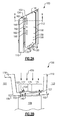
- FIG. 2A illustrates a platform 102 for a turbine flowpath component 100, such as a vane or a blade outer air seal.
- the platform 102 mounts a vane within a flowpath of a gas turbine engine. The illustrated view is drawn from a viewpoint exterior to an engine and looking radially inward.
- the turbine flowpath component 100 includes multiple connection features 110, 112 for connecting the platform 102 to an engine static structure.
- a turbine flowpath component cover 120 Positioned on a radially outward facing surface of the platform 102 is a turbine flowpath component cover 120.
- the turbine flowpath component cover 120 is a sheet metal component cut or stamped to a desired shape.
- the turbine flowpath component cover 120 can be constructed of other materials, or via other techniques and serve the same function.
- the illustrated turbine flowpath component cover 120 of Figure 2A includes multiple impingement holes 130.
- the impingement holes 130 allow cooling air to pass through the turbine flowpath component cover 120 as impingement jets and impinge on the platform 102 radially inward of the turbine flowpath component cover 120.
- the impingement jets formed by this arrangement cool the platform 102.
- Also included in the turbine flowpath component cover 120 are multiple serpentine cooling passage inlets 160 and outlets 162.
- the outlets 162 are film cooling holes. Cooling air is inlet into each of multiple serpentine passages (illustrated in Figure 3 ) contained in platform 102 through the inlets 160.
- Figure 2B illustrates a cross sectional view of the turbine flowpath component 100 along view line B-B.
- the illustrated connection features 110, 112 are generic connection features 110, 112.
- the specific geometry of each connection feature 110, 112, including any fastener holes, notches, or other intrusions or protrusions depends on the specific engine into which the turbine flowpath component 100 is being connected.
- the platform 102 defines a radially inward edge of the turbine flowpath component 100 structure, and includes a flowpath surface 106. If the turbine flowpath component 100 is a blade outer airseal, the flowpath surface 106 faces a turbine blade 108. If the turbine flowpath component 100 is a vane, flowpath surface 106 attaches to an airfoil (not shown).
- the turbine flowpath component cover 120 is positioned radially outward of an internal cooling cavity 140.
- the internal cooling cavity 140 includes multiple walls (illustrated in Figure 3 ) protruding radially outward from the platform 102, and contacting the turbine flowpath component cover 120.
- the combination of the platform 102, the walls and the turbine flowpath component cover 120 defines multiple internal cooling passages within the internal cooling cavity 140.
- the walls are integral to the platform 102. In other examples, the walls are a distinct structure or an integral part of the turbine flowpath component cover 120.
- the turbine flowpath component cover 120 defines a radially outward boundary of the internal cooling cavity 140, and a radially outward boundary of the internal passages within the internal cooling cavity 140.
- at least one of the internal cooling passages defined by the internal cooling cavity 140, the turbine flowpath component cover 120, and the radially outward protruding walls provide an impingement cooling flow into an impingement cavity.
- cooling air 150 is directed radially inward onto the turbine flowpath component cover 120.
- the cooling air 150 passes through the impingement holes 130 and impinges on the platform 102, providing cooling according to known impingement cooling principles.
- the cooling air 150 can be provided from another source and passed over the turbine flowpath component cover 120.
- Some passages defined within the internal cooling cavity 140 are serpentine cooling passages, and the cooling air 150 enters the passages through at least one cooling air inlet 160.
- the cooling air 150 passes through the serpentine passages and is outlet through a serpentine cooling passage outlet 162. As the cooling air passes through the passage the cooling air cools the platform 102 using convective cooling.
- the cooling air 150 can be provided to the serpentine passages from another source or the inlets 160 and outlets 162 can be positioned in alternating locations in alternate examples.
- Fluids passing through a passage increase in velocity as the passage is restricted in size. Furthermore, as a cooling fluid increases in velocity, the thermal transfer rates, and ability of the fluid to cool the passage may increase. As such, locally increasing the velocity of a cooling flow at an area requiring increased cooling improves the cooling effectiveness. In the illustrated example, a downstream edge 103 of the platform 102 requires increased cooling relative to an upstream edge 101. Further, locally decreasing the velocity of cooling flow at an area requiring decreased cooling transfers less heat to the cooling flow, leaving more capacity to cool subsequent areas of the cooling passage. This more efficiently uses the cooling fluid than previously known arrangements.
- the turbine flowpath component cover 120 includes three portions, 122, 124, 126.
- An upstream portion 122 defines a first radial height 123 between the platform 102 and the turbine flowpath component cover 120.
- a downstream portion 126 defines a second radial height 127. While described herein as an "upstream portion” 122 and a “downstream portion” 126, one of skill in the art, having the benefit of this disclosure will recognize that the upstream portion 122 is upstream relative to gaspath flow, and the label upstream does not reflect the position of the upstream portion 122 relative to coolant flow.
- downstream portion is downstream relative to gaspath flow, and the label downstream does not reflect the position of the downstream portion relative to coolant flow.
- a transitional portion 124 defined between the upstream portion 122 and the downstream portion 126 is a transitional portion 124.
- the radial height defined between the turbine flowpath component cover 120 and the platform 102 in the transitional portion transitions from the first radial height 123 to the second radial height 127.
- the cross-sectional area of the passage is restricted, thereby driving a localized velocity increases in the cooling fluid passing through the passage.
- the second radial height 127 is less than the first radial height 123.
- the first radial height 123 is 0.100 inches (0.254 centimeters) and the second radial height 127 is 0.080 inches (0.203 centimeters).
- the lengths of the first radial height can be within the range of 0.085 - 0.115 inches (0.216-0.292 centimeters) and the length of the second radial height can be within the range of 0.065 - 0.095 inches (0.165-0.241 centimeters).
- the difference between the first radial height 123 and the second radial height 127 is at least 0.010 inches (0.025 centimeters).
- the magnitude of the localized flow velocity increase is dependent upon the change in radial height, with a greater change resulting in a greater localized increase.
- the upstream portion 122 is closer to an upstream edge 101 of the turbine flowpath component 100 and the downstream portion 126 is closer to a downstream edge 103 of the turbine flowpath component 100.
- the angle of the transition portion 124 is aligned with, and transitions along, a direction of flow through a core flowpath of the gas turbine engine. In alternative examples, the angle of the transition portion 124 can be aligned with fluid flow through the passages defined in the internal cooling cavity 140.
- fluid flow velocity through the passages within the internal cooling cavity 140 is increased in the more restricted portions of the passages (the downstream portion) relative to the fluid flow velocity through the less restricted portions of the passages (the upstream portions).
- Such a configuration provides increased cooling to the downstream portions where the illustrated platform is more vulnerable to extreme temperatures.
- the relative radial heights 123, 127 of the turbine flowpath component cover 120 can be reversed, with the upstream portion 122 being more restricted (having a lesser radial height) than the downstream portion 124.
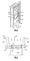
- Figure 3 illustrates the view of Figure 2A with the removal of the turbine flowpath component cover 120.
- Multiple passage defining features 180 such as walls, protrude radially outward from the platform 102. The features 180 contact the turbine flowpath component cover 120 when the turbine flowpath component cover 120 is installed.
- the illustrated passage defining features 180 define multiple serpentine passages 170, with two inlets 160 and two outlets 162.
- each of the inlets 160 is a hole, or other opening, in the turbine flowpath component cover 120 that allows the cooling air 150 to enter the internal cooling cavity.
- each of the outlets 162 is illustrated as a smaller hole or opening that allows fluid to exits the cavity.
- An impingement cavity 190 is also defined by the passage defining features 180. The impingement cavity 190 functions in the manner described above with regards to Figures 2A and 2B .
- Figure 4 illustrates the cross section of Figure 2B in an alternative arrangement. Rather than including the three discrete portions 122, 124, 126 of the turbine flowpath component cover 120, the alternative of Figure 4 utilizes a single transition region that extends from the upstream side 101 of the blade outer air seal to the downstream side 103 of the blade outer air seal.
- the restriction of the radial height of the internal cavity 140 operates similarly to the discrete portions 122, 124, 126 described above with regards to Figure 2B , with the exception that the transition region extends the full length of the internal cavity.
- the singular transition region can be achieved by utilizing a varied depth of the platform base in conjunction with a straight turbine flowpath component cover 120, or by angling the turbine flowpath component cover 120 relative to the platform 102.
Landscapes
- Engineering & Computer Science (AREA)
- Mechanical Engineering (AREA)
- General Engineering & Computer Science (AREA)
- Chemical & Material Sciences (AREA)
- Combustion & Propulsion (AREA)
- Turbine Rotor Nozzle Sealing (AREA)
Applications Claiming Priority (1)
| Application Number | Priority Date | Filing Date | Title |
|---|---|---|---|
| US201462082233P | 2014-11-20 | 2014-11-20 |
Publications (2)
| Publication Number | Publication Date |
|---|---|
| EP3023596A1 true EP3023596A1 (de) | 2016-05-25 |
| EP3023596B1 EP3023596B1 (de) | 2019-01-02 |
Family
ID=54608417
Family Applications (1)
| Application Number | Title | Priority Date | Filing Date |
|---|---|---|---|
| EP15195483.1A Active EP3023596B1 (de) | 2014-11-20 | 2015-11-19 | Innengekühlte turbinenplattform |
Country Status (2)
| Country | Link |
|---|---|
| US (1) | US10502092B2 (de) |
| EP (1) | EP3023596B1 (de) |
Families Citing this family (2)
| Publication number | Priority date | Publication date | Assignee | Title |
|---|---|---|---|---|
| US10927694B2 (en) * | 2019-03-13 | 2021-02-23 | Raytheon Technologies Corporation | BOAS carrier with cooling supply |
| US11815022B2 (en) | 2021-08-06 | 2023-11-14 | Rtx Corporation | Platform serpentine re-supply |
Citations (5)
| Publication number | Priority date | Publication date | Assignee | Title |
|---|---|---|---|---|
| EP0709550A1 (de) * | 1994-10-31 | 1996-05-01 | General Electric Company | Gekühlter Gehäusering |
| EP1176285A2 (de) * | 2000-07-27 | 2002-01-30 | General Electric Company | Kühlung für einen Turbinenmantelring |
| US20030131980A1 (en) * | 2002-01-16 | 2003-07-17 | General Electric Company | Multiple impingement cooled structure |
| US20080131260A1 (en) * | 2006-11-30 | 2008-06-05 | Ching-Pang Lee | Method and system to facilitate cooling turbine engines |
| US8814507B1 (en) * | 2013-05-28 | 2014-08-26 | Siemens Energy, Inc. | Cooling system for three hook ring segment |
Family Cites Families (20)
| Publication number | Priority date | Publication date | Assignee | Title |
|---|---|---|---|---|
| US4526226A (en) * | 1981-08-31 | 1985-07-02 | General Electric Company | Multiple-impingement cooled structure |
| US5092735A (en) | 1990-07-02 | 1992-03-03 | The United States Of America As Represented By The Secretary Of The Air Force | Blade outer air seal cooling system |
| US5486090A (en) * | 1994-03-30 | 1996-01-23 | United Technologies Corporation | Turbine shroud segment with serpentine cooling channels |
| US5538393A (en) * | 1995-01-31 | 1996-07-23 | United Technologies Corporation | Turbine shroud segment with serpentine cooling channels having a bend passage |
| US5562408A (en) * | 1995-06-06 | 1996-10-08 | General Electric Company | Isolated turbine shroud |
| JP3680167B2 (ja) * | 2001-07-11 | 2005-08-10 | エーザイ株式会社 | 味識別装置及び識別方法 |
| US6905302B2 (en) * | 2003-09-17 | 2005-06-14 | General Electric Company | Network cooled coated wall |
| US7207771B2 (en) * | 2004-10-15 | 2007-04-24 | Pratt & Whitney Canada Corp. | Turbine shroud segment seal |
| EP1990507B1 (de) * | 2006-03-02 | 2015-04-15 | IHI Corporation | Prallkühlungsstruktur |
| FR2907841B1 (fr) | 2006-10-30 | 2011-04-15 | Snecma | Secteur d'anneau de turbine de turbomachine |
| US8147192B2 (en) * | 2008-09-19 | 2012-04-03 | General Electric Company | Dual stage turbine shroud |
| US8181443B2 (en) * | 2008-12-10 | 2012-05-22 | Pratt & Whitney Canada Corp. | Heat exchanger to cool turbine air cooling flow |
| US8740551B2 (en) | 2009-08-18 | 2014-06-03 | Pratt & Whitney Canada Corp. | Blade outer air seal cooling |
| FR2955891B1 (fr) | 2010-02-02 | 2012-11-16 | Snecma | Secteur d'anneau de turbine de turbomachine |
| US9080458B2 (en) | 2011-08-23 | 2015-07-14 | United Technologies Corporation | Blade outer air seal with multi impingement plate assembly |
| US9500099B2 (en) * | 2012-07-02 | 2016-11-22 | United Techologies Corporation | Cover plate for a component of a gas turbine engine |
| US9828880B2 (en) * | 2013-03-15 | 2017-11-28 | General Electric Company | Method and apparatus to improve heat transfer in turbine sections of gas turbines |
| US9464538B2 (en) * | 2013-07-08 | 2016-10-11 | General Electric Company | Shroud block segment for a gas turbine |
| US20150198063A1 (en) * | 2014-01-14 | 2015-07-16 | Alstom Technology Ltd | Cooled stator heat shield |
| US10400627B2 (en) * | 2015-03-31 | 2019-09-03 | General Electric Company | System for cooling a turbine engine |
-
2015
- 2015-11-19 EP EP15195483.1A patent/EP3023596B1/de active Active
- 2015-11-19 US US14/945,556 patent/US10502092B2/en active Active
Patent Citations (5)
| Publication number | Priority date | Publication date | Assignee | Title |
|---|---|---|---|---|
| EP0709550A1 (de) * | 1994-10-31 | 1996-05-01 | General Electric Company | Gekühlter Gehäusering |
| EP1176285A2 (de) * | 2000-07-27 | 2002-01-30 | General Electric Company | Kühlung für einen Turbinenmantelring |
| US20030131980A1 (en) * | 2002-01-16 | 2003-07-17 | General Electric Company | Multiple impingement cooled structure |
| US20080131260A1 (en) * | 2006-11-30 | 2008-06-05 | Ching-Pang Lee | Method and system to facilitate cooling turbine engines |
| US8814507B1 (en) * | 2013-05-28 | 2014-08-26 | Siemens Energy, Inc. | Cooling system for three hook ring segment |
Also Published As
| Publication number | Publication date |
|---|---|
| EP3023596B1 (de) | 2019-01-02 |
| US10502092B2 (en) | 2019-12-10 |
| US20160146044A1 (en) | 2016-05-26 |
Similar Documents
| Publication | Publication Date | Title |
|---|---|---|
| EP2944764B1 (de) | Bauteil eines gasturbinentriebwerks, zugehöriges gasturbinentriebwerk und kühlverfahren | |
| EP3009599A1 (de) | Gasturbinenbauteil mit filmkühlungsöffnung. | |
| EP3043027B1 (de) | Gasturbinenmotorkomponente mit konformem kehlkühlungspfad | |
| EP3063388B1 (de) | Sockel mit wärmetransferverstärker | |
| EP2993304B1 (de) | Gasturbinenmotorkomponente mit filmkühlungsloch | |
| EP3042041B1 (de) | Gasturbinenmotorflügelturbulator für flügelkriechbeständigkeit | |
| EP3181823B1 (de) | Verfahren und vorrichtung zur kühlung einer gasturbinenmotorschaufel | |
| WO2014159800A1 (en) | Obtuse angle chevron trip strip | |
| EP3354853B1 (de) | Turbinenschaufel mit schlitzfilmkühlung und herstellungsverfahren | |
| EP3246524B1 (de) | Beaufschlagungsverteiler | |
| EP3266983B1 (de) | Kühlsystem für eine schaufel einer gasturbine | |
| EP2993303B1 (de) | Gasturbinenkomponente mit filmkühlloch mit tasche | |
| EP3009600A1 (de) | Turbinenschaufel mit spitzenkühlung eines gasturbinentriebwerks | |
| EP3502420B1 (de) | Bauteil für ein gasturbinentriebwerk und zugehöriges gasturbinentriebwerk | |
| EP3023596B1 (de) | Innengekühlte turbinenplattform | |
| EP3246520A2 (de) | Verfahren und vorrichtung zur verbesserung des laminarstroms für gasturbinenmotorkomponenten | |
| EP3508693B1 (de) | Segregierte kühlluftkanäle für turbinenschaufel | |
| EP2947272A1 (de) | Gasturbinen mit statorschaufel mit kühleinsatz | |
| US12065945B2 (en) | Internally cooled turbine blade | |
| EP3581762B1 (de) | Kühlkanalanordnung für gasturbinendeckband | |
| EP3502417B1 (de) | Ströumungsumlenkelemente einer plattform für gasturbinenmotorkomponenten | |
| EP3067521B1 (de) | Turbinenleitschaufel mit prallkühleinsätzen mit abdeckplatten für variierende toleranzen |
Legal Events
| Date | Code | Title | Description |
|---|---|---|---|
| AK | Designated contracting states |
Kind code of ref document: A1 Designated state(s): AL AT BE BG CH CY CZ DE DK EE ES FI FR GB GR HR HU IE IS IT LI LT LU LV MC MK MT NL NO PL PT RO RS SE SI SK SM TR |
|
| AX | Request for extension of the european patent |
Extension state: BA ME |
|
| PUAI | Public reference made under article 153(3) epc to a published international application that has entered the european phase |
Free format text: ORIGINAL CODE: 0009012 |
|
| RAP1 | Party data changed (applicant data changed or rights of an application transferred) |
Owner name: UNITED TECHNOLOGIES CORPORATION |
|
| STAA | Information on the status of an ep patent application or granted ep patent |
Free format text: STATUS: REQUEST FOR EXAMINATION WAS MADE |
|
| 17P | Request for examination filed |
Effective date: 20161122 |
|
| RBV | Designated contracting states (corrected) |
Designated state(s): AL AT BE BG CH CY CZ DE DK EE ES FI FR GB GR HR HU IE IS IT LI LT LU LV MC MK MT NL NO PL PT RO RS SE SI SK SM TR |
|
| RIC1 | Information provided on ipc code assigned before grant |
Ipc: F01D 9/04 20060101AFI20170131BHEP Ipc: F01D 25/24 20060101ALI20170131BHEP Ipc: F02C 3/04 20060101ALI20170131BHEP Ipc: F01D 11/08 20060101ALI20170131BHEP Ipc: F01D 25/12 20060101ALI20170131BHEP |
|
| STAA | Information on the status of an ep patent application or granted ep patent |
Free format text: STATUS: EXAMINATION IS IN PROGRESS |
|
| 17Q | First examination report despatched |
Effective date: 20170620 |
|
| GRAP | Despatch of communication of intention to grant a patent |
Free format text: ORIGINAL CODE: EPIDOSNIGR1 |
|
| STAA | Information on the status of an ep patent application or granted ep patent |
Free format text: STATUS: GRANT OF PATENT IS INTENDED |
|
| INTG | Intention to grant announced |
Effective date: 20180620 |
|
| GRAS | Grant fee paid |
Free format text: ORIGINAL CODE: EPIDOSNIGR3 |
|
| GRAA | (expected) grant |
Free format text: ORIGINAL CODE: 0009210 |
|
| STAA | Information on the status of an ep patent application or granted ep patent |
Free format text: STATUS: THE PATENT HAS BEEN GRANTED |
|
| AK | Designated contracting states |
Kind code of ref document: B1 Designated state(s): AL AT BE BG CH CY CZ DE DK EE ES FI FR GB GR HR HU IE IS IT LI LT LU LV MC MK MT NL NO PL PT RO RS SE SI SK SM TR |
|
| REG | Reference to a national code |
Ref country code: GB Ref legal event code: FG4D |
|
| REG | Reference to a national code |
Ref country code: CH Ref legal event code: EP Ref country code: AT Ref legal event code: REF Ref document number: 1084631 Country of ref document: AT Kind code of ref document: T Effective date: 20190115 |
|
| REG | Reference to a national code |
Ref country code: DE Ref legal event code: R096 Ref document number: 602015022683 Country of ref document: DE |
|
| REG | Reference to a national code |
Ref country code: IE Ref legal event code: FG4D |
|
| REG | Reference to a national code |
Ref country code: NL Ref legal event code: MP Effective date: 20190102 |
|
| REG | Reference to a national code |
Ref country code: LT Ref legal event code: MG4D |
|
| REG | Reference to a national code |
Ref country code: AT Ref legal event code: MK05 Ref document number: 1084631 Country of ref document: AT Kind code of ref document: T Effective date: 20190102 |
|
| PG25 | Lapsed in a contracting state [announced via postgrant information from national office to epo] |
Ref country code: NL Free format text: LAPSE BECAUSE OF FAILURE TO SUBMIT A TRANSLATION OF THE DESCRIPTION OR TO PAY THE FEE WITHIN THE PRESCRIBED TIME-LIMIT Effective date: 20190102 |
|
| PG25 | Lapsed in a contracting state [announced via postgrant information from national office to epo] |
Ref country code: SE Free format text: LAPSE BECAUSE OF FAILURE TO SUBMIT A TRANSLATION OF THE DESCRIPTION OR TO PAY THE FEE WITHIN THE PRESCRIBED TIME-LIMIT Effective date: 20190102 Ref country code: LT Free format text: LAPSE BECAUSE OF FAILURE TO SUBMIT A TRANSLATION OF THE DESCRIPTION OR TO PAY THE FEE WITHIN THE PRESCRIBED TIME-LIMIT Effective date: 20190102 Ref country code: ES Free format text: LAPSE BECAUSE OF FAILURE TO SUBMIT A TRANSLATION OF THE DESCRIPTION OR TO PAY THE FEE WITHIN THE PRESCRIBED TIME-LIMIT Effective date: 20190102 Ref country code: FI Free format text: LAPSE BECAUSE OF FAILURE TO SUBMIT A TRANSLATION OF THE DESCRIPTION OR TO PAY THE FEE WITHIN THE PRESCRIBED TIME-LIMIT Effective date: 20190102 Ref country code: NO Free format text: LAPSE BECAUSE OF FAILURE TO SUBMIT A TRANSLATION OF THE DESCRIPTION OR TO PAY THE FEE WITHIN THE PRESCRIBED TIME-LIMIT Effective date: 20190402 Ref country code: PT Free format text: LAPSE BECAUSE OF FAILURE TO SUBMIT A TRANSLATION OF THE DESCRIPTION OR TO PAY THE FEE WITHIN THE PRESCRIBED TIME-LIMIT Effective date: 20190502 Ref country code: PL Free format text: LAPSE BECAUSE OF FAILURE TO SUBMIT A TRANSLATION OF THE DESCRIPTION OR TO PAY THE FEE WITHIN THE PRESCRIBED TIME-LIMIT Effective date: 20190102 |
|
| PG25 | Lapsed in a contracting state [announced via postgrant information from national office to epo] |
Ref country code: IS Free format text: LAPSE BECAUSE OF FAILURE TO SUBMIT A TRANSLATION OF THE DESCRIPTION OR TO PAY THE FEE WITHIN THE PRESCRIBED TIME-LIMIT Effective date: 20190502 Ref country code: LV Free format text: LAPSE BECAUSE OF FAILURE TO SUBMIT A TRANSLATION OF THE DESCRIPTION OR TO PAY THE FEE WITHIN THE PRESCRIBED TIME-LIMIT Effective date: 20190102 Ref country code: GR Free format text: LAPSE BECAUSE OF FAILURE TO SUBMIT A TRANSLATION OF THE DESCRIPTION OR TO PAY THE FEE WITHIN THE PRESCRIBED TIME-LIMIT Effective date: 20190403 Ref country code: RS Free format text: LAPSE BECAUSE OF FAILURE TO SUBMIT A TRANSLATION OF THE DESCRIPTION OR TO PAY THE FEE WITHIN THE PRESCRIBED TIME-LIMIT Effective date: 20190102 Ref country code: HR Free format text: LAPSE BECAUSE OF FAILURE TO SUBMIT A TRANSLATION OF THE DESCRIPTION OR TO PAY THE FEE WITHIN THE PRESCRIBED TIME-LIMIT Effective date: 20190102 Ref country code: BG Free format text: LAPSE BECAUSE OF FAILURE TO SUBMIT A TRANSLATION OF THE DESCRIPTION OR TO PAY THE FEE WITHIN THE PRESCRIBED TIME-LIMIT Effective date: 20190402 |
|
| REG | Reference to a national code |
Ref country code: DE Ref legal event code: R097 Ref document number: 602015022683 Country of ref document: DE |
|
| PG25 | Lapsed in a contracting state [announced via postgrant information from national office to epo] |
Ref country code: RO Free format text: LAPSE BECAUSE OF FAILURE TO SUBMIT A TRANSLATION OF THE DESCRIPTION OR TO PAY THE FEE WITHIN THE PRESCRIBED TIME-LIMIT Effective date: 20190102 Ref country code: CZ Free format text: LAPSE BECAUSE OF FAILURE TO SUBMIT A TRANSLATION OF THE DESCRIPTION OR TO PAY THE FEE WITHIN THE PRESCRIBED TIME-LIMIT Effective date: 20190102 Ref country code: EE Free format text: LAPSE BECAUSE OF FAILURE TO SUBMIT A TRANSLATION OF THE DESCRIPTION OR TO PAY THE FEE WITHIN THE PRESCRIBED TIME-LIMIT Effective date: 20190102 Ref country code: AT Free format text: LAPSE BECAUSE OF FAILURE TO SUBMIT A TRANSLATION OF THE DESCRIPTION OR TO PAY THE FEE WITHIN THE PRESCRIBED TIME-LIMIT Effective date: 20190102 Ref country code: IT Free format text: LAPSE BECAUSE OF FAILURE TO SUBMIT A TRANSLATION OF THE DESCRIPTION OR TO PAY THE FEE WITHIN THE PRESCRIBED TIME-LIMIT Effective date: 20190102 Ref country code: SK Free format text: LAPSE BECAUSE OF FAILURE TO SUBMIT A TRANSLATION OF THE DESCRIPTION OR TO PAY THE FEE WITHIN THE PRESCRIBED TIME-LIMIT Effective date: 20190102 Ref country code: DK Free format text: LAPSE BECAUSE OF FAILURE TO SUBMIT A TRANSLATION OF THE DESCRIPTION OR TO PAY THE FEE WITHIN THE PRESCRIBED TIME-LIMIT Effective date: 20190102 Ref country code: AL Free format text: LAPSE BECAUSE OF FAILURE TO SUBMIT A TRANSLATION OF THE DESCRIPTION OR TO PAY THE FEE WITHIN THE PRESCRIBED TIME-LIMIT Effective date: 20190102 |
|
| PLBE | No opposition filed within time limit |
Free format text: ORIGINAL CODE: 0009261 |
|
| STAA | Information on the status of an ep patent application or granted ep patent |
Free format text: STATUS: NO OPPOSITION FILED WITHIN TIME LIMIT |
|
| PG25 | Lapsed in a contracting state [announced via postgrant information from national office to epo] |
Ref country code: SM Free format text: LAPSE BECAUSE OF FAILURE TO SUBMIT A TRANSLATION OF THE DESCRIPTION OR TO PAY THE FEE WITHIN THE PRESCRIBED TIME-LIMIT Effective date: 20190102 |
|
| 26N | No opposition filed |
Effective date: 20191003 |
|
| PG25 | Lapsed in a contracting state [announced via postgrant information from national office to epo] |
Ref country code: SI Free format text: LAPSE BECAUSE OF FAILURE TO SUBMIT A TRANSLATION OF THE DESCRIPTION OR TO PAY THE FEE WITHIN THE PRESCRIBED TIME-LIMIT Effective date: 20190102 |
|
| PG25 | Lapsed in a contracting state [announced via postgrant information from national office to epo] |
Ref country code: TR Free format text: LAPSE BECAUSE OF FAILURE TO SUBMIT A TRANSLATION OF THE DESCRIPTION OR TO PAY THE FEE WITHIN THE PRESCRIBED TIME-LIMIT Effective date: 20190102 |
|
| REG | Reference to a national code |
Ref country code: CH Ref legal event code: PL |
|
| PG25 | Lapsed in a contracting state [announced via postgrant information from national office to epo] |
Ref country code: MC Free format text: LAPSE BECAUSE OF FAILURE TO SUBMIT A TRANSLATION OF THE DESCRIPTION OR TO PAY THE FEE WITHIN THE PRESCRIBED TIME-LIMIT Effective date: 20190102 Ref country code: LI Free format text: LAPSE BECAUSE OF NON-PAYMENT OF DUE FEES Effective date: 20191130 Ref country code: CH Free format text: LAPSE BECAUSE OF NON-PAYMENT OF DUE FEES Effective date: 20191130 Ref country code: LU Free format text: LAPSE BECAUSE OF NON-PAYMENT OF DUE FEES Effective date: 20191119 |
|
| REG | Reference to a national code |
Ref country code: BE Ref legal event code: MM Effective date: 20191130 |
|
| PG25 | Lapsed in a contracting state [announced via postgrant information from national office to epo] |
Ref country code: IE Free format text: LAPSE BECAUSE OF NON-PAYMENT OF DUE FEES Effective date: 20191119 |
|
| PG25 | Lapsed in a contracting state [announced via postgrant information from national office to epo] |
Ref country code: BE Free format text: LAPSE BECAUSE OF NON-PAYMENT OF DUE FEES Effective date: 20191130 |
|
| PG25 | Lapsed in a contracting state [announced via postgrant information from national office to epo] |
Ref country code: CY Free format text: LAPSE BECAUSE OF FAILURE TO SUBMIT A TRANSLATION OF THE DESCRIPTION OR TO PAY THE FEE WITHIN THE PRESCRIBED TIME-LIMIT Effective date: 20190102 |
|
| PG25 | Lapsed in a contracting state [announced via postgrant information from national office to epo] |
Ref country code: HU Free format text: LAPSE BECAUSE OF FAILURE TO SUBMIT A TRANSLATION OF THE DESCRIPTION OR TO PAY THE FEE WITHIN THE PRESCRIBED TIME-LIMIT; INVALID AB INITIO Effective date: 20151119 Ref country code: MT Free format text: LAPSE BECAUSE OF FAILURE TO SUBMIT A TRANSLATION OF THE DESCRIPTION OR TO PAY THE FEE WITHIN THE PRESCRIBED TIME-LIMIT Effective date: 20190102 |
|
| PG25 | Lapsed in a contracting state [announced via postgrant information from national office to epo] |
Ref country code: MK Free format text: LAPSE BECAUSE OF FAILURE TO SUBMIT A TRANSLATION OF THE DESCRIPTION OR TO PAY THE FEE WITHIN THE PRESCRIBED TIME-LIMIT Effective date: 20190102 |
|
| REG | Reference to a national code |
Ref country code: DE Ref legal event code: R081 Ref document number: 602015022683 Country of ref document: DE Owner name: RAYTHEON TECHNOLOGIES CORPORATION (N.D.GES.D.S, US Free format text: FORMER OWNER: UNITED TECHNOLOGIES CORPORATION, FARMINGTON, CONN., US Ref country code: DE Ref legal event code: R081 Ref document number: 602015022683 Country of ref document: DE Owner name: RTX CORPORATION (N.D.GES.D. STAATES DELAWARE),, US Free format text: FORMER OWNER: UNITED TECHNOLOGIES CORPORATION, FARMINGTON, CONN., US |
|
| P01 | Opt-out of the competence of the unified patent court (upc) registered |
Effective date: 20230520 |
|
| REG | Reference to a national code |
Ref country code: DE Ref legal event code: R081 Ref document number: 602015022683 Country of ref document: DE Owner name: RTX CORPORATION (N.D.GES.D. STAATES DELAWARE),, US Free format text: FORMER OWNER: RAYTHEON TECHNOLOGIES CORPORATION (N.D.GES.D.STAATES DELAWARE), ARLINGTON, VA, US |
|
| PGFP | Annual fee paid to national office [announced via postgrant information from national office to epo] |
Ref country code: DE Payment date: 20251022 Year of fee payment: 11 |
|
| PGFP | Annual fee paid to national office [announced via postgrant information from national office to epo] |
Ref country code: GB Payment date: 20251023 Year of fee payment: 11 |
|
| PGFP | Annual fee paid to national office [announced via postgrant information from national office to epo] |
Ref country code: FR Payment date: 20251022 Year of fee payment: 11 |