EP3029212A2 - Hohldecke mit brandschutzgehäuse sowie brandschutzgehäuse - Google Patents
Hohldecke mit brandschutzgehäuse sowie brandschutzgehäuse Download PDFInfo
- Publication number
- EP3029212A2 EP3029212A2 EP15196518.3A EP15196518A EP3029212A2 EP 3029212 A2 EP3029212 A2 EP 3029212A2 EP 15196518 A EP15196518 A EP 15196518A EP 3029212 A2 EP3029212 A2 EP 3029212A2
- Authority
- EP
- European Patent Office
- Prior art keywords
- fire protection
- protection housing
- opening
- planking
- fire
- Prior art date
- Legal status (The legal status is an assumption and is not a legal conclusion. Google has not performed a legal analysis and makes no representation as to the accuracy of the status listed.)
- Granted
Links
Images



Classifications
-
- E—FIXED CONSTRUCTIONS
- E04—BUILDING
- E04B—GENERAL BUILDING CONSTRUCTIONS; WALLS, e.g. PARTITIONS; ROOFS; FLOORS; CEILINGS; INSULATION OR OTHER PROTECTION OF BUILDINGS
- E04B9/00—Ceilings; Construction of ceilings, e.g. false ceilings; Ceiling construction with regard to insulation
- E04B9/001—Ceilings; Construction of ceilings, e.g. false ceilings; Ceiling construction with regard to insulation characterised by provisions for heat or sound insulation
-
- F—MECHANICAL ENGINEERING; LIGHTING; HEATING; WEAPONS; BLASTING
- F21—LIGHTING
- F21S—NON-PORTABLE LIGHTING DEVICES; SYSTEMS THEREOF; VEHICLE LIGHTING DEVICES SPECIALLY ADAPTED FOR VEHICLE EXTERIORS
- F21S8/00—Lighting devices intended for fixed installation
- F21S8/02—Lighting devices intended for fixed installation of recess-mounted type, e.g. downlighters
- F21S8/026—Lighting devices intended for fixed installation of recess-mounted type, e.g. downlighters intended to be recessed in a ceiling or like overhead structure, e.g. suspended ceiling
-
- F—MECHANICAL ENGINEERING; LIGHTING; HEATING; WEAPONS; BLASTING
- F21—LIGHTING
- F21V—FUNCTIONAL FEATURES OR DETAILS OF LIGHTING DEVICES OR SYSTEMS THEREOF; STRUCTURAL COMBINATIONS OF LIGHTING DEVICES WITH OTHER ARTICLES, NOT OTHERWISE PROVIDED FOR
- F21V25/00—Safety devices structurally associated with lighting devices
- F21V25/12—Flameproof or explosion-proof arrangements
- F21V25/125—Flameproof or explosion-proof arrangements using intumescent material, i.e. using materials which swells up as a result of heat exposure
Definitions
- the invention relates to a hollow ceiling with the underside of the hollow ceiling forming planking and with a positioned behind the planking fire protection housing for electrical installations, wherein the planking has an opening in the region of the arrangement of the fire protection housing.
- a similar embodiment is from the EP 0427498 B1 known.
- such embodiments are not suitable for fire protection purposes, as they form from the opening of the hollow ceiling large free spaces in the rear area, which allow the passage of air or fire gases.
- a lamp with lamp housing is known in which the lamp housing is a usable in a perforation of a ceiling or wall molding made of elastomeric material.
- the lamp housing is a usable in a perforation of a ceiling or wall molding made of elastomeric material.
- Such a configuration makes it possible to insert and hold this light from the front in the corresponding opening of a hollow ceiling.
- the installation space provided by this embodiment is very limited and is also one such arrangement not suitable for fire protection purposes.
- the invention is based on the object to provide a hollow ceiling with a fire enclosure available in which a dimensionally stable and heat-resistant fire protection housing from the front of the hollow ceiling forth through the opening of the hollow ceiling can be mounted and positioned behind the hollow ceiling is that the opening is completely covered by the fire protection housing.
- the opening is rectangular with a length L and a width B
- the fire protection housing is dimensionally stable and forms a parallelepiped shape with a length LB, a width BB and a height HB, whose base surface in installation collage at the Rear side of the planking abuts and has an installation opening
- the width BB of the fire protection housing is equal to the length L of the opening or shorter than this length L
- the height HB of the fire enclosure equal to the width B the opening is dimensioned or shorter than this width B
- the length LB of the fire protection housing is greater than the length L of the opening and the width BB of the fire protection housing is greater than the width B of the opening dimensioned.
- the cuboid fire protection housing through the rectangular opening by the fire protection housing with a narrow front side inserted into the opening from below and pushed to behind the planking. Subsequently, the housing can be aligned parallel to the back of the planking and rotated by 90 degrees, in which case a situation is created in which the opening is completely covered by the fire protection housing, so no gap between the soffit of the opening and the fire enclosure, but that Fire enclosure completely covers the opening and its edges.
- the fire protection housing made of sheet steel, so that it is not only dimensionally stable and can withstand appropriate loads, but also sufficiently stable in temperature, so that it can withstand a fire-related time sufficient fire-induced temperature effect, even in case of fire.
- the hollow ceiling can be constructed in a conventional manner, wherein the planking example, by plasterboard or the like, preferably in multiple layers, may be formed and preferably complies with the fire safety regulations.
- the fitter may receive a template attached to the fire protection housing, which represents the dimension of the installation opening, so that the fitter can accordingly cut the installation opening into the planking of the hollow ceiling. Subsequently, the fire protection housing can be inserted and positioned. Subsequently, all peripheral edges of the installation opening are covered in such a way that they lie within the space surrounded by the fire protection housing.
- the fire enclosure can be very large dimensions. For example, dimensions of 250 mm Length, 200 mm width and 100 mm height possible. It is thus a large installation space provided within the fire enclosure, so that a whole range of electrical components can be installed in the housing.
- the supply line of supply cables can be done by appropriate wall openings preferably in the region of the end walls of the fire protection housing.
- the fire protection housing has internally a coating or an insert of intumescent material that leaves the installation opening.
- the rectangular Beplankungsausschnitt cut out of the planking which is cut out to form the opening of the hollow ceiling, after installation of the fire protection housing is inserted back into the opening and fixed to the planking or preferably on the fire protection housing.
- This Beplankungsausites may initially be a closed surface element, so that the installation opening for the installation of electrical components in the fire protection housing is not yet accessible. It is practically achieved a blind arrangement. If this item is then to install electrotechnical components to be used, at least one installation opening can be cut out of the planking cutout in a partial area. Through this installation opening installations can be fed, for example, can be installed in these installation openings electrical lights or speakers.
- the Plankungsausites can be connected after insertion into the opening, for example, with the peripheral edges of the opening, for example, be plastered. It is also possible the Cladding cut in another way to attach to the planking. It is preferably provided that the Beplankungsausites is attached to components of the fire protection housing, so that a durable and durable arrangement is achieved.
- a particularly preferred development is seen in the fact that in the area of the fire protection housing which is opposite to the planking base and forms the bottom of the fire protection housing, there is a plate on the there located intumescent coating or the area located there of the insert of intumescent material made of temperature-resistant material is fastened by means of at least one anchor, which has an area measurement that is larger than the installation opening in the planking cutout.
- a plate made of temperature-resistant material by means of at least one anchor attached can also serve several anchors for attachment.
- This plate has such a surface dimension that is at least greater than the installation opening in the planking cutout. At most, this plate could have a design that corresponds to the clear width of the fire protection housing between the components of intumescent material.
- the purpose of this embodiment is that, for example, in case of fire, if in the fire enclosure by external influences a temperature arises, which brings the intumescent material to increase in volume, due to this softening and foaming of the material, the connection is released to the anchors, so that the plate after can fall down towards the installation opening.
- the built-in device such as the lamp or the speaker
- burns or falls out of the housing thereby the resulting opening by means of the plate be closed at least so far that the intumescent intumescent material is not or hardly discharged from the housing.
- the intumescent intumescent material may condense within the housing to form a temperature insulating line.
- screws can be used as anchor for attachment, by means of which the plate is held on the intumescent material.
- a further preferred embodiment is seen in that the arranged in the fire protection housing insert is made of intumescent material shape similar to the shape of the fire protection housing, wherein between the side walls and the bottom wall of these parts, an air gap is formed.
- an air gap is formed between the wall of the fire protection housing and the use of intumescent material, which acts insulating and thus the fire protection purpose is conducive.
- flange parts are formed or formed, which protrude into the opening of the planking, wherein the inserted into the opening planking cutout with Fastening means that pass through this, is releasably or permanently attached to the flange, and / or that are formed or molded on the mouth edge of the fire enclosure for transversely outwardly or inwardly projecting flange, which rest against the back of the planking next to the opening and the means of the planking are fastened to the planking thorough fastening means.
- This configuration ensures that the fastening means for fastening the fire protection housing to the planking and the means for fastening the planking cutout in the opening of the planking is achieved by components which are formed on the fire protection housing itself.
- components which are formed on the fire protection housing itself For example, at the preferably made of sheet fire enclosure flanges or Flange parts are formed and angled at right angles, which protrude transversely into the opening of the planking, so that the subsequently re-inserted into the opening plank cutout can be applied against these flange to achieve the desired positioning and then with fasteners that pass through the Plankungsausschnitt and in the Flange parts are screwed or otherwise secured to this, a detachable or non-detachable attachment takes place.
- the flange parts can have a plurality of perforations into which fastening means can be screwed at different points.
- the same is provided with respect to the projecting transversely outward flange or even inwardly projecting flange on the mouth edge of the fire protection housing.
- These flange portions may be angled outwardly and then abut the back of the planking or they may also be angled inwardly so that they are positioned in the edge region between the edge of the side walls of the firestop box and the opening in the planking. Again, these are by screws or the like, which can be screwed from the front of the planking forth through the planking and can be screwed into the flange, fixed.
- the invention further relates to a fire protection housing for electrical installations, wherein the fire protection housing has internally a coating or an insert of intumescent material and consists of heat-resistant, dimensionally stable material, wherein the fire protection housing has a bottom and a mouth facing away from this, the mouth opening by a fire - And / or heat-resistant first plate is closed, which has at least one installation opening for the installation of electrical fittings.
- Such fire protection housings are known in the art.
- a problem is that electrical installations in particular lights or speakers, which are installed in the installation opening of the fire or heat-resistant plate, in case of fire, when acting from the bottom of a fire, although the Intumescent material which is located within the fire enclosure, foams and increases in volume, but this material at the location where the built-in device was located, which is burned by fire or falls out of the opening can escape.
- the invention has for its object here to achieve an improved fire protection.
- the invention proposes that in the area of the fire protection housing, which is adjacent to the ground, attached to the intumescent coating or the area of the insert located there by means of at least one anchor, a second plate of temperature-resistant material, which has a surface design, which corresponds to the cross section of the fire protection housing or at least greater than the installation opening of the first plate.
- the plate made of temperature-resistant material inside the fire protection housing is achieved that when temperature-induced reaction of intumescent material, the anchor connection with this material is released so that the plate can fall down (normal installation direction vertical). This plate then at least partially closes the installation opening, wherein the intumescent intumescent material can not or only slightly be discharged from the housing. Instead, the intumescent material is compacted in the housing and forms an elevated Temperaturisolierumble.
- an air gap is formed between the insert of intumescent material and the wall and the bottom of the fire protection housing.
- the first plate is releasably or permanently attached to the fire protection housing.
- the first plate must therefore not be an integral part of the fire protection housing, but they can, for example, for the purpose of installing electrical fittings the mouth of the Fire protection housing can be removed releasing and inserted only after complete or partial installation of the electrical installations in the mouth of the fire protection housing and releasably attached to the fire protection housing or inextricably attached.
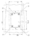
- planking 1 a bottom of a hollow ceiling forming planking 1 is shown, which consists of two layers of plasterboard. Furthermore, a positioned in the installed position behind the planking 1 fire protection housing 2 is shown, which is used for electrical installations.
- the planking 1 is provided in the region of the arrangement of the fire protection housing 2 with an opening 3, in particular in FIG. 2 is clearly visible. This opening 3 is rectangular with a length L and a width B.
- the fire protection housing 2 is dimensionally stable and consists for example of a one-piece sheet metal housing, which is easy to manufacture and can be formed from a one-piece sheet metal blank. This fire protection housing 2 forms a cuboid shape with a length LB of a width BB and a height HB.
- the fire protection housing 2 has a Installation opening 5 on.
- the width BB of the fire protection housing 2 is at most equal to the length L of the opening 3 dimensioned or even shorter than this length L.
- the height HB of the fire protection housing 2 is equal to the width B of the opening 3 dimensioned or shorter than this width B.
- the length LB of the fire protection housing 2 is greater than the length L of the opening 3.
- the width BB of the fire protection housing 2 is greater than the width B of the opening 3 dimensioned.
- the assembly of the fire enclosure 2 from the bottom of the planking 1 ago done by the fire protection housing 2 is pushed through the opening 3 of the planking 1, in such an orientation that the fire protection housing 2 with its narrow end face by the Installation opening 3 of the planking 1 is inserted from below and moved upwards.
- the fire protection box 1 can be rotated about its longitudinal axis, so that the installation target position is achieved in FIG. 1 and 2 is shown.
- the installation opening 3 is complete covered by the fire enclosure 2, so that all four boundary edges of the mounting hole 3 are within the housing components surrounded by the fire enclosure 2.
- the fire protection housing 2 is provided internally with an insert 6 made of intumescent material which leaves the installation opening 5 free. Incidentally, this use of the shape and dimensions of the fire protection housing 2 is substantially adapted.
- the rectangular Beplankungsausschnitt 7 of the planking 1 cut out to form the opening 3 in the planking 1 forms a closed surface element, wherein in the embodiment, a portion of this Beplankungsausiteses 7 an installation opening 8 for the installation of electrical fittings, such as a lamp or a speaker, having.
- a plate 10 of temperature-resistant material by means of anchoring 11 is held in the interior of the fire protection housing 2, specifically at its bottom 9 at the area of the intumescent coating or the area of the insert 6 made of intumescent material located there.
- This plate 10 has an areal extent which is greater than the installation opening 8 in the planking cutout 7.
- the plate 10 is slightly smaller than the bottom surface of the insert 6.
- This configuration serves to ensure that, in the event of fire, ie, when a high temperature is present in the fire protection housing 2, which causes the intumescent material to foam, the connection between the anchors 11 and the intumescent material, for example, of the insert 6 is dissolved.
- the plate 10 falls under gravity downward in the direction of the installation opening 8. If a fire load from below pending and possibly built into the installation opening 8 device z. As a lamp or a loudspeaker, burns or falls out of the housing, the thus released opening can be closed by the plate 10 at least so far that the foaming material is not or hardly discharged from the housing.
- the intumescent material may instead be in the Compress fire protection housing 2 and form a temperature insulation section.
- the insert 6 arranged in the fire protection housing 2 is made of intumescent material similar in shape to the shape of the fire protection housing 2, such as in FIG FIG. 1 is apparent.
- an air gap 12 is formed between the side walls of the insert 6 and the fire protection housing 2 and between the bottom wall and the bottom wall of the insert 6, so that here a Heilisolierumble is formed.
- FIG. 3 and FIG. 4 can be seen, at the mouth edge of the fire protection housing 2, which forms the voltage applied to the rear side of the planking 1 base 4, the formation of transversely projecting flange 13 is provided, which protrude into the opening 3 of the planking 1.
- the inserted into the opening 3 Plankungsausites 7 is fastened with fastening means, such as screws, which reach through this on the flange 13 detachably or non-detachably attached.
- the flange parts 13 have several Holes or the like, which can serve for the use of fastening means, in particular screws.
- FIG. 3 is also at the mouth edge projecting transversely outside the arrangement of flange 14, which rest against the opening 3 at the rear of the planking 1. It can thus be provided by the planking 1, the arrangement of fasteners, in particular screws that pass through the planking 1 and engage in holes in the flange 14, so that the fire enclosure 2 is attached to the planking 1.
- the flange 14 may also be provided that in the area of the base 4 between the flanges 13 additional mounting holes are arranged, which serve for the use of fferbefest Trentsffenn or the like, which are guided by the planking 1 and by means of which the fire protection housing 2 at the Planking is fastened.
- the invention is also a fire protection housing 2 for electrical Installations, which has internally a coating or insert 6 of intumescent material and which consists of heat-resistant, dimensionally stable material.
- the fire protection housing 2 has a bottom 9 and a mouth opening 5 facing away from the bottom.
- the mouth opening 5 can be closed by a fire and / or heat resistant first plate having at least one installation opening comparable to the opening 8 for the installation of electrical fittings.
- the cross section of the fire protection housing 2 corresponds approximately, but at least greater than the installation opening 8 in the first plate.
- an air gap 12 is formed between the insert 6 and the wall and the bottom 9 of the fire protection housing 2, which forms a HeilisolierSCH.
- the first plate which closes the opening 5 of the fire protection housing 2, is preferably releasably or non-detachably fastened to the fire protection housing 2.
Landscapes
- Engineering & Computer Science (AREA)
- Architecture (AREA)
- Physics & Mathematics (AREA)
- Electromagnetism (AREA)
- Civil Engineering (AREA)
- Structural Engineering (AREA)
- Casings For Electric Apparatus (AREA)
- Fire Alarms (AREA)
- Building Environments (AREA)
Abstract
Description
- Die Erfindung betrifft eine Hohldecke mit einer die Unterseite der Hohldecke bildenden Beplankung sowie mit einem hinter der Beplankung positionierten Brandschutzgehäuse für elektrotechnische Installationen, wobei die Beplankung im Bereich der Anordnung des Brandschutzgehäuses eine Öffnung aufweist.
- Im Stand der Technik ist es bekannt, an einer Hohldecke rückseitig ein Gehäuse anzuordnen, welches elektrotechnische Einbauten aufnimmt. Dieses Gehäuse ist rückseitig der Beplankung der Hohldecke angeordnet und zwar im Bereich einer Öffnung der Beplankung. Diese Öffnung ist zum Einsatz beispielsweise einer Leuchte geeignet und bestimmt. Die Leuchte kann in diese Öffnung eingesetzt werden und an dieser fixiert werden.
- Der Einbau des Gehäuses durch diese Öffnung ist nicht möglich, da das Gehäuse erheblich größer dimensioniert ist als diese Öffnung, die für den Einsatz der Leuchte bestimmt ist. Demzufolge ist die Installation aufwendig und nur dann möglich, wenn der hinter der Beplankung liegende Raum der Hohldecke für die Montage zugänglich ist.
- Dieser Stand der Technik ist in der
WO 2004/018934A1 angegeben und erläutert. Des Weiteren ist es bekannt, haubenartige Abdeckgehäuse für Einbauleuchten vorzusehen, die ausgehend von einer Bodenplatte Beine aufweisen, die elastisch bewegt werden können. Zum Einbau in eine Hohldecke ist eine entsprechende Öffnung in der Hohldecke vorgesehen. Durch diese Öffnung kann das Abdeckgehäuse mit zusammengedrückten Beinen eingeschoben werden. Die Beine spreizen anschließend hinter der Einbauöffnung oder in dieser auf und ermöglichen einen festen Sitz in der Einbauöffnung, wobei zusätzlich eine Einbauleuchte in diesem Element angeordnet werden kann. Beispiele für solche Ausgestaltungen sind derDE 19937617 C2 , derDE 20217028 U1 und derDE 202007012107 U1 zu entnehmen. - Eine ähnliche Ausgestaltung ist aus der
EP 0427498 B1 bekannt. Solche Ausgestaltungen sind aber für Brandschutzzwecke nicht geeignet, da sie von der Öffnung der Hohldecke ausgehend große Freiräume in den hinteren Bereich bilden, die den Durchzug von Luft oder auch Brandgasen ermöglichen. - Aus der
DE 4338841 A1 ist eine Leuchte mit Lampengehäuse bekannt, bei der das Lampengehäuse ein in eine Lochung einer Decke oder Wand einsetzbares Formteil aus gummielastischem Werkstoff ist. Eine solche Ausgestaltung ermöglicht es, diese Leuchte von der Vorderseite her in die entsprechende Öffnung einer Hohldecke einzusetzen und zu halten. Der durch diese Ausgestaltung zur Verfügung gestellte Einbauraum ist sehr begrenzt zudem ist auch eine solche Anordnung nicht für Brandschutzzwecke geeignet. - Ausgehend von diesem Stand der Technik liegt der Erfindung die Aufgabe zu Grunde, eine Hohldecke mit einem Brandschutzgehäuse zur Verfügung zu stellen, bei der ein formstabiles und hitzebeständiges Brandschutzgehäuse von der Vorderseite der Hohldecke her durch die Öffnung der Hohldecke montierbar ist und hinter der Hohldecke so positionierbar ist, dass die Öffnung insgesamt von dem Brandschutzgehäuse abgedeckt ist.
- Zur Lösung dieser Aufgabe wird vorgeschlagen, dass die Öffnung rechteckig mit einer Länge L und einer Breite B ist, dass das Brandschutzgehäuse formstabil ist und eine Quaderform mit einer Länge LB, einer Breite BB und einer Höhe HB bildet, dessen eine Grundfläche in Einbausollage an der Hinterseite der Beplankung anliegt und eine Installationsöffnung aufweist, und dass die Breite BB des Brandschutzgehäuses gleich der Länge L der Öffnung bemessen ist oder kürzer als diese Länge L, und die Höhe HB des Brandschutzgehäuses gleich der Breite B der Öffnung bemessen ist oder kürzer als diese Breite B ist, und dass die Länge LB des Brandschutzgehäuses größer als die Länge L der Öffnung und die Breite BB des Brandschutzgehäuses größer als die Breite B der Öffnung bemessen ist.
- Gemäß dieser Anordnung und Ausgestaltung ist es möglich, das quaderförmige Brandschutzgehäuse durch die rechteckige Öffnung zu montieren, indem das Brandschutzgehäuse mit einer schmalen Stirnseite voraus in die Öffnung von unten her eingeschoben und bis hinter die Beplankung geschoben wird. Anschließend kann das Gehäuse parallel zur Rückseite der Beplankung ausgerichtet und um 90 Grad gedreht werden, wobei dann eine Einbausituation erzeugt ist, in der die Öffnung vollständig von dem Brandschutzgehäuse überdeckt ist, also keine Spalte zwischen der Laibung der Öffnung und dem Brandschutzgehäuse entstehen, sondern das Brandschutzgehäuse deckt vollständig die Öffnung und deren Randkanten ab.
- Vorzugsweise besteht das Brandschutzgehäuse aus Stahlblech, sodass es nicht nur formstabil ist und entsprechenden Belastungen standhalten kann, sondern auch ausreichend temperaturstabil ist, sodass es auch im Brandfalle eine ausreichende Zeit einer brandbedingten Temperatureinwirkung standhalten kann.
- Die Hohldecke kann in üblicher Weise aufgebaut sein, wobei die Beplankung beispielsweise durch Gipskartonplatten oder dergleichen, vorzugsweise mehrlagig, gebildet sein kann und vorzugsweise den Brandschutzbestimmungen entspricht.
- Zur Montage kann der Monteur eine zu dem Brandschutzgehäuse beigefügte Schablone erhalten, die die Abmessung der Einbauöffnung darstellt, sodass der Monteur entsprechend die Einbauöffnung in die Beplankung der Hohldecke schneiden kann. Anschließend kann das Brandschutzgehäuse eingeführt und positioniert werden. Nachfolgend erfolgt eine Abdeckung aller Randkanten der Einbauöffnung in der Weise, dass sie innerhalb des von dem Brandschutzgehäuse umgebenen Raumes liegen.
- Das Brandschutzgehäuse kann sehr groß dimensioniert werden. So sind beispielsweise Abmessungen von 250 mm Länge, 200 mm Breite und 100 mm Höhe möglich. Es wird damit ein großer Installationsraum innerhalb des Brandschutzgehäuses zur Verfügung gestellt, sodass eine ganze Reihe elektrotechnischer Komponenten in das Gehäuse eingebaut werden können. Die Zuleitung von Zuleitungskabeln kann durch entsprechende Wandungsöffnungen vorzugsweise im Bereich der Stirnwandungen des Brandschutzgehäuses erfolgen.
- Eine für Brandschutzzwecke besonders bevorzugte Weiterbildung wird darin gesehen, dass das Brandschutzgehäuse innenliegend eine Beschichtung oder einen Einsatz aus intumeszierendem Material aufweist, die oder der die Installationsöffnung freilässt.
- Hierdurch wird erreicht, dass im Brandfalle eine erhebliche Volumenvergrößerung des intumeszierendem Materials bewirkt wird, was dazu führt, dass das Brandschutzgehäuse und auch die Installationsöffnung von intumeszierendem Material ausgefüllt wird, sodass das Durchziehen von Brandgasen und Rauchgasen sowie der unmittelbare Feuerdurchtritt unterbunden ist. Eine besonders bevorzugte Weiterbildung wird darin gesehen, dass der zur Bildung der Öffnung in der Beplankung aus der Beplankung ausgeschnittene rechteckige Beplankungsausschnitt in die Öffnung eingefügt und in dieser Position entweder an der Beplankung oder am Brandschutzgehäuse befestigt ist, wobei der Beplankungsausschnitt ein geschlossenes Flächenelement bildet oder ein Teilbereich mindestens eine Installationsöffnung zur Installation von elektrotechnischen Einbauten aufweist.
- Gemäß dieser Ausgestaltung wird der aus der Beplankung ausgeschnittene rechteckige Beplankungsausschnitt, der zur Bildung der Öffnung aus der Hohldecke ausgeschnitten wird, nach Montage des Brandschutzgehäuses wieder in die Öffnung eingefügt und an der Beplankung oder vorzugsweise am Brandschutzgehäuse befestigt. Dieser Beplankungsausschnitt kann zunächst ein geschlossenes Flächenelement sein, sodass die Installationsöffnung zur Installation von elektrotechnischen Bauteilen in dem Brandschutzgehäuse noch nicht zugänglich ist. Es ist praktisch eine Blindanordnung erreicht. Sofern dieses Element dann zur Installation von elektrotechnischen Bestandteilen genutzt werden soll, kann aus dem Beplankungsausschnitt in einem Teilbereich mindestens eine Installationsöffnung ausgeschnitten werden. Durch diese Installationsöffnung können Installationen zugeführt werde, beispielsweise können in diese Installationsöffnungen elektrische Leuchten oder auch Lautsprecher eingebaut werden.
- Es ist auch möglich, die Anordnung von elektrotechnischen Komponenten und die Zuordnung der elektrotechnischen Verdrahtung vorzunehmen, bevor der Beplankungsausschnitt in die Öffnung eingefügt wird, sodass anschließend die Einfügung des Beplankungsausschnittes in die Öffnung erfolgt und nachträglich nur noch die Verdrahtung der Leuchte oder des Lautsprechers oder dergleichen erfolgt, welcher in die Installationsöffnung des Beplankungsausschnittes eingesetzt werden kann.
- Der Beplankungsausschnitt kann nach dem Einfügen in die Öffnung beispielsweise mit den Randkanten der Öffnung verbunden werden, beispielsweise eingegipst werden. Es ist auch möglich, den Beplankungsausschnitt in anderer Weise an der Beplankung zu befestigen. Vorzugsweise ist vorgesehen, dass der Beplankungsausschnitt an Bestandteilen des Brandschutzgehäuses befestigt wird, sodass eine dauerhafte und haltbare Anordnung erreicht ist.
- Eine besonders bevorzugte Weiterbildung wird darin gesehen, dass im Bereich des Brandschutzgehäuses, der der an der Beplankung anliegenden Grundfläche gegenüber liegt und den Boden des Brandschutzgehäuses bildet, an der dort befindlichen innenliegenden, intumeszierenden Beschichtung oder dem dort befindlichen Bereich des Einsatzes aus intumeszierendem Material eine Platte aus temperaturbeständigem Material mittels mindestens eines Ankers befestigt ist, die eine Flächenbemessung hat, die größer als die Installationsöffnung in dem Beplankungsausschnitt ist.
- Gemäß dieser Ausgestaltung ist quasi am Boden des Brandschutzgehäuses, der dessen die Installationsöffnungen bildenden Grundfläche gegenüber liegt, und zwar an der dort befindlichen innenliegenden intumeszierenden Beschichtung oder dem dort befindlichen Bereich des Einsatzes aus intumeszierendem Material eine Platte aus temperaturbeständigem Material mittels mindestens eines Ankers befestigt. Es können auch mehrere Anker zur Befestigung dienen. Diese Platte hat eine solche Flächenbemessung, die zumindest größer ist als die Installationsöffnung in dem Beplankungsausschnitt. Maximal könnte diese Platte eine Bemessung haben, die der lichten Weite des Brandschutzgehäuses zwischen den Bestandteilen aus intumeszierendem Material entspricht. Der Sinn dieser Ausgestaltung ist, dass beispielsweise im Brandfall, wenn in dem Brandschutzgehäuse durch äußere Einflüsse eine Temperatur entsteht, die das intumeszierende Material zur Volumenvergrößerung bringt, bedingt durch diese Erweichung und Aufschäumung des Materials die Verbindung zu den Ankern gelöst wird, sodass die Platte nach unten in Richtung der Installationsöffnung fallen kann. Bei einer Brandlast von unten, durch die eventuell das eingebaute Gerät, beispielsweise die Leuchte oder der Lautsprecher, verbrennt oder aus dem Gehäuse herausfällt, kann dadurch die entstehende Öffnung mittels der Platte mindestens so weit geschlossen werden, dass das aufschäumende intumeszierenden Material nicht oder kaum aus dem Gehäuse ausgetragen wird. Das aufschäumende intumeszierende Material kann sich innerhalb des Gehäuses verdichten, sodass eine Temperaturisolierstrecke gebildet wird.
- Als Anker zur Befestigung können beispielsweise Schrauben verwendet werden, mittels derer die Platte an dem intumeszierendem Material gehalten wird.
- Eine des weiteren bevorzugte Ausgestaltung wird darin gesehen, dass der im Brandschutzgehäuse angeordnete Einsatz aus intumeszierendem Material formähnlich der Form des Brandschutzgehäuses ausgebildet ist, wobei zwischen den Seitenwänden und der Bodenwand dieser Teile ein Luftspalt ausgebildet ist.
- Gemäß dieser Ausgestaltung wird zwischen der Wandung des Brandschutzgehäuses und dem Einsatz aus intumeszierendem Material ein Luftspalt gebildet, der isolierend wirkt und damit dem Brandschutzzweck förderlich ist.
- Des Weiteren wird bevorzugt vorgesehen, dass an dem Mündungsrand des Brandschutzgehäuses , der die an der Hinterseite der Beplankung anliegende Grundfläche bildet oder Bestandteile derselben ist, Flanschteile ausgebildet oder angeformt sind, die in die Öffnung der Beplankung hineinragen, wobei der in die Öffnung eingefügte Beplankungsausschnitt mit Befestigungsmitteln, die diesen durchgreifen, an den Flanschteilen lösbar oder unlösbar befestigt ist, und/oder dass am Mündungsrand des Brandschutzgehäuses nach quer außen oder innen abragende Flanschteile ausgebildet oder angeformt sind, die an der Hinterseite der Beplankung neben der Öffnung anliegen und die mittels die Beplankung durchgreifender Befestigungsmittel an der Beplankung befestigt sind.
- Durch diese Ausgestaltung wird erreicht, dass die Befestigungsmittel zur Befestigung des Brandschutzgehäuses an der Beplankung und die Mittel zur Befestigung des Beplankungsausschnittes in der Öffnung der Beplankung durch Bestandteile erreicht wird, die am Brandschutzgehäuse selbst ausgebildet sind. Beispielsweise können an dem vorzugsweise aus Blech bestehende Brandschutzgehäuse Flansche oder Flanschteile angeformt und rechtwinklig abgewinkelt werden, die quer in die Öffnung der Beplankung hineinragen, sodass der nachfolgend in die Öffnung wieder eingefügte Beplankungsausschnitt gegen diese Flanschteile angelegt werden kann, um die gewünschte Positionierung zu erreichen und dann mit Befestigungsmitteln, die den Beplankungsausschnitt durchgreifen und in die Flanschteile eingeschraubt werden oder in anderer Weise an diesen befestigt werden, eine lösbare oder unlösbare Befestigung erfolgt. Die Flanschteile können dazu mehrere Lochungen aufweisen, in die an unterschiedlichen Stellen Befestigungsmittel eingeschraubt werden können. Gleiches ist bezüglich der nach quer außen abragenden Flanschteile oder auch nach innen abragenden Flanschteile am Mündungsrand des Brandschutzgehäuses vorgesehen. Diese Flanschteile können nach außen abgewinkelt sein und dann rückseitig auf der Beplankung anliegen oder sie können auch nach innen abgewinkelt sein, sodass sie in dem Randbereich zwischen der Kante der Seitenwandungen des Brandschutzkastens und der Öffnung in der Beplankung positioniert sind. Auch diese sind wiederum durch Schrauben oder dergleichen, die von der Vorderseite der Beplankung her durch die Beplankung geschraubt werden können und in die Flanschteile eingeschraubt werden können, fixierbar.
- Gegenstand der Erfindung ist ferner ein Brandschutzgehäuse für elektrotechnische Installationen, wobei das Brandschutzgehäuse innenliegend eine Beschichtung oder einen Einsatz aus intumeszierendem Material aufweist und aus wärmebeständigem, formstabilem Material besteht, wobei das Brandschutzgehäuse einen Boden und eine diesem abgewandte Mündungsöffnung aufweist, wobei die Mündungsöffnung durch eine feuer- und/oder hitzeresistente erste Platte verschlossen ist, die mindestens eine Installationsöffnung zur Installation von elektrotechnischen Einbauten aufweist.
- Solche Brandschutzgehäuse sind im Stand der Technik bekannt. Ein Problem besteht dabei darin, dass elektrotechnische Installationen insbesondere Leuchten oder auch Lautsprecher, die in die Installationsöffnung der feuer- oder hitzeresistenten Platte eingebaut sind, im Brandfalle, wenn von der Unterseite her eine Brandlast einwirkt, zwar das intumeszierende Material, welches innerhalb des Brandschutzgehäuses befindlich ist, aufschäumt und im Volumen vergrößert wird, jedoch dieses Material an dem Ort, an dem sich das eingebaute Gerät befunden hat, welches durch Brandeinwirkung verbrannt ist oder aus der Öffnung herausfällt, austreten kann.
- Der Erfindung liegt die Aufgabe zugrunde hier einen verbesserten Brandschutz zu erreichen. Zur Lösung dieser Aufgabe schlägt die Erfindung vor, dass im Bereich des Brandschutzgehäuses, der dem Boden benachbart ist, an der intumeszierenden Beschichtung oder dem dort befindlichen Bereich des Einsatzes mittels mindestens eines Ankers eine zweite Platte aus temperaturbeständigem Material befestigt ist, die eine Flächenbemessung hat, die dem Querschnitt des Brandschutzgehäuses entspricht oder mindestens größer ist als die Installationsöffnung der ersten Platte.
- Durch die Anordnung der Platte aus temperaturbeständigem Material im Inneren des Brandschutzgehäuses wird erreicht, dass bei temperaturbedingter Reaktion des intumeszierendem Materials die Ankerverbindung mit diesem Material gelöst wird, sodass die Platte nach unten Fallen kann (normale Einbaurichtung vertikal). Diese Platte verschließt dann zumindest teilweise die Installationsöffnung, wobei das aufschäumende intumeszierende Material nicht oder nur wenig aus dem Gehäuse ausgetragen werden kann. Stattdessen wird das intumeszierende Material im Gehäuse verdichtet und bildet eine erhöhte Temperaturisolierstrecke.
- Bevorzugt ist hierbei vorgesehen, dass zwischen dem Einsatz aus intumeszierendem Material und der Wandung sowie dem Boden des Brandschutzgehäuses ein Luftspalt ausgebildet ist.
- Hierdurch wird eine zusätzliche Isolierung erreicht.
- Bevorzugt ist zudem vorgesehen, dass die erste Platte lösbar oder unlösbar am Brandschutzgehäuse befestigt ist.
- Die erste Platte muss also nicht integraler Bestandteil des Brandschutzgehäuses sein, sondern sie kann beispielsweise zum Zwecke der Installation von elektrotechnischen Einbauten die Mündung des Brandschutzgehäuses freigebend entfernt werden und erst nach vollständigem oder teilweisen Einbau der Elektroinstallationen in die Mündung des Brandschutzgehäuses eingefügt werden und lösbar am Brandschutzgehäuse oder auch unlösbar daran befestigt werden.
- Ausführungsbeispiele der Erfindung sind in der Zeichnung dargestellt und im Folgenden näher beschrieben.
- Es zeigt:
-
Fig.1 eine Hohldecke mit Brandschutzgehäuse in einer Montagesolllage, teilweise aufgebrochen; -
Fig.2 eine Ansicht einer Hohldecke mit hinter der Hohldecke angeordnetem Brandschutzgehäuse von unten gesehen; -
Fig.3 ein Brandschutzgehäuse in Ansicht; -
Fig.4 eine alternative eines Brandschutzgehäuses ebenfalls in Ansicht; -
Fig.5 desgleichen von schräg oben gesehen. - In der Zeichnung ist eine die Unterseite einer Hohldecke bildende Beplankung 1 gezeigt, die aus zwei Lagen von Gipskartonplatten besteht. Des Weiteren ist ein in Einbaulage hinter der Beplankung 1 positioniertes Brandschutzgehäuse 2 gezeigt, welches für elektrotechnische Installationen dient. Die Beplankung 1 ist im Bereich der Anordnung des Brandschutzgehäuses 2 mit einer Öffnung 3 versehen, die insbesondere in
Figur 2 gut ersichtlich ist. Diese Öffnung 3 ist rechteckig mit einer Länge L und einer Breite B. Das Brandschutzgehäuse 2 ist formstabil und besteht beispielsweise aus einem einstückigen Blechgehäuse, welches einfach zu fertigen ist und aus einem einteiligen Blechzuschnitt geformt werden kann. Dieses Brandschutzgehäuse 2 bildet eine Quaderform mit einer Länge LB einer Breite BB und einer Höhe HB. - Wie insbesondere in
Figur 1 ersichtlich, liegt seine Grundfläche 4 an der Hinterseite der Beplankung 1 an. Des Weiteren weist das Brandschutzgehäuse 2 eine Installationsöffnung 5 auf. Die Breite BB des Brandschutzgehäuses 2 ist maximal gleich der Länge L der Öffnung 3 bemessen oder aber auch kürzer als diese Länge L. Die Höhe HB des Brandschutzgehäuses 2 ist gleich der Breite B der Öffnung 3 bemessen oder auch kürzer als diese Breite B. Die Länge LB des Brandschutzgehäuses 2 ist größer als die Länge L der Öffnung 3. Schließlich ist die Breite BB des Brandschutzgehäuses 2 größer als die Breite B der Öffnung 3 bemessen. - Entsprechend dieser Abmessung und Ausgestaltung kann die Montage des Brandschutzgehäuses 2 von der Unterseite der Beplankung 1 her erfolgen indem das Brandschutzgehäuse 2 durch die Öffnung 3 der Beplankung 1 geschoben wird, und zwar in einer solchen Orientierung, dass das Brandschutzgehäuse 2 mit seiner schmalen Stirnseite durch die Einbauöffnung 3 der Beplankung 1 von unten eingeschoben und nach oben verschoben wird. Anschließend kann der Brandschutzkasten 1 um seine Längsachse gedreht werden, sodass die Einbausolllage erreicht wird, die in
Figur 1 und2 gezeigt ist. In dieser Solllage wird die Einbauöffnung 3 vollständig vom Brandschutzgehäuse 2 überdeckt, sodass alle vier Begrenzungskanten der Einbauöffnung 3 innerhalb der vom Brandschutzgehäuse 2 umgebenen Gehäusebestandteile liegen. Im Ausführungsbeispiel ist das Brandschutzgehäuse 2 innenliegend mit einem Einsatz 6 aus intumeszierendem Material ausgestattet, der die Installationsöffnung 5 freilässt. Im Übrigen ist dieser Einsatz der Form und Abmessung des Brandschutzgehäuses 2 im Wesentlichen angepasst. - Der zur Bildung der Öffnung 3 in der Beplankung 1 aus der Beplankung 1 ausgeschnittene rechteckige Beplankungsausschnitt 7 der Beplankung 1 bildet ein geschlossenes Flächenelement, wobei im Ausführungsbeispiel ein Teilbereich dieses Beplankungsausschnittes 7 eine Installationsöffnung 8 zur Installation von elektrotechnischen Einbauten, beispielsweise einer Leuchte oder einem Lautsprecher, aufweist. Des Weiteren ist im Inneren des Brandschutzgehäuses 2 und zwar an dessen Boden 9 an dem dort befindlichen Bereich der intumeszierenden Beschichtung bzw. dem dort befindlichen Bereich des Einsatzes 6 aus intumeszierendem Material eine Platte 10 aus temperaturbeständigem Material mittels Ankern 11 gehalten ist. Diese Platte 10 hat eine Flächenerstreckung, die größer als die Installationsöffnung 8 in dem Beplankungsausschnitt 7 ist. Vorzugsweise ist die Platte 10 etwas kleiner als die Bodenfläche des Einsatzes 6.
- Diese Ausgestaltung dient dazu, dass im Brandfall, wenn also in dem Brandschutzgehäuse 2 eine hohe Temperatur ansteht, welche das intumeszierende Material zum Aufschäumen bringt, die Verbindung zwischen den Ankern 11 und dem intumeszierendem Material beispielsweise des Einsatzes 6 aufgelöst wird. In diesem Falle fällt die Platte 10 unter Schwerkrafteinwirkung nach unten in Richtung der Installationsöffnung 8. Wenn eine Brandlast von unten ansteht und möglicherweise das in die Installationsöffnung 8 eingebaute Gerät z. B. eine Leuchte oder ein Lautsprecher, verbrennt oder aus dem Gehäuse herausfällt, so kann die dadurch freigegebene Öffnung durch die Platte 10 mindestens so weit wieder verschlossen werden, dass das aufschäumende Material nicht oder kaum aus dem Gehäuse ausgetragen wird. Das intumeszierende Material kann sich stattdessen im Brandschutzgehäuse 2 verdichten und eine Temperaturisolierstrecke bilden.
- Des Weiteren ist der im Brandschutzgehäuse 2 angeordnete Einsatz 6 aus intumeszierendem Material formähnlich der Form des Brandschutzgehäuses 2 ausgebildet, wie beispielsweise in
Figur 1 ersichtlich ist. Dabei ist zwischen den Seitenwänden des Einsatzes 6 und des Brandschutzgehäuses 2 und zwischen dessen Bodenwand und der Bodenwand des Einsatzes 6 ein Luftspalt 12 ausgebildet, sodass hier eine Luftisolierstrecke gebildet ist. - Wie beispielsweise aus
Figur 3 undFigur 4 ersichtlich, ist am Mündungsrand des Brandschutzgehäuses 2, der die an der Hinterseite der Beplankung 1 anliegende Grundfläche 4 bildet, die Ausbildung von quer abragenden Flanschteilen 13 vorgesehen, die in die Öffnung 3 der Beplankung 1 hineinragen. Der in die Öffnung 3 eingefügte Beplankungsausschnitt 7 wird mit Befestigungsmitteln, beispielsweise Schrauben, die diesen durchgreifen an den Flanschteilen 13 lösbar oder auch unlösbar befestigt. Die Flanschteile 13 weisen mehrere Lochungen oder dergleichen auf, die zum Einsatz von Befestigungsmitteln, insbesondere Schrauben dienen können. - Im Ausführungsbeispiel nach
Figur 3 ist auch am Mündungsrand nach quer außen abragend die Anordnung von Flanschteilen 14 vorgesehen, die an der Hinterseite der Beplankung 1 neben der Öffnung 3 anliegen. Es kann somit durch die Beplankung 1 die Anordnung von Befestigungsmitteln, insbesondere Schrauben vorgesehen werden, die die Beplankung 1 durchgreifen und in Lochungen der Flanschteile 14 eingreifen, sodass das Brandschutzgehäuse 2 an der Beplankung 1 befestigt wird. Anstelle der Ausbildung der Flanschteile 14 kann auch vorgesehen sein, dass im Bereich der Grundfläche 4 zwischen den Flanschen 13 zusätzliche Befestigungslochungen angeordnet sind, die zum Einsatz von Schraubbefestigungsmitteln oder dergleichen dienen, die durch die Beplankung 1 geführt sind und mittels derer das Brandschutzgehäuse 2 an der Beplankung befestigbar ist. - Gegenstand der Erfindung ist zudem ein Brandschutzgehäuse 2 für elektrotechnische Installationen, welches innenliegend eine Beschichtung oder einen Einsatz 6 aus intumeszierendem Material aufweist und welches aus wärmebeständigem, formstabilem Material besteht. Das Brandschutzgehäuse 2 weist einen Boden 9 und eine dem Boden abgewandte Mündungsöffnung 5 auf. Die Mündungsöffnung 5 kann durch eine feuer- und/oder hitzeresistente erste Platte verschlossen werden, die mindestens eine Installationsöffnung vergleichbar der Öffnung 8 zur Installation von elektrotechnischen Einbauten aufweist. Bei dieser Ausgestaltung ist im Bereich des Brandschutzgehäuses 2, der dem Boden 9 benachbart ist, an der intumeszierenden Beschichtung oder an dem dort befindlichen Bereich des Einsatzes 6 mittels mindestens eines Ankers 11 eine zweite Platte 10 aus temperaturbeständigem Material befestigt, die eine Flächenbemessung hat, die dem Querschnitt des Brandschutzgehäuses 2 in etwa entspricht, mindestens aber größer ist als die Installationsöffnung 8 in der ersten Platte. Auch hierbei wird im Brandfall die Wirkung erreicht, die oben bezüglich der entsprechenden Einbauten des Brandschutzgehäuses beschrieben ist.
- Auch bei dieser Ausgestaltung ist zwischen dem Einsatz 6 sowie der Wandung und dem Boden 9 des Brandschutzgehäuses 2 ein Luftspalt 12 ausgebildet, der eine Luftisolierstrecke bildet.
- Die erste Platte, die die Öffnung 5 des Brandschutzgehäuses 2 verschließt, ist vorzugsweise lösbar oder auch unlösbar am Brandschutzgehäuse 2 befestig.
- Es wird damit ein autarkes Brandschutzgehäuse zur Verfügung gestellt, welches den Brandschutz fördert, insbesondere das Durchdringen von Rauchgasen und Flammen durch die Öffnung 8 und das Brandschutzgehäuse 2 verhindert.
- Die Erfindung ist nicht auf die Ausführungsbeispiele beschränkt, sondern im Rahmen der Offenbarung vielfach variabel.
- Alle in der Beschreibung und/oder Zeichnung offenbarten Einzel- und Kombinationsmerkmale werden als erfindungswesentlich angesehen.
-
- 1
- Beplankung
- 2
- Brandschutzgehäuse
- 3
- Öffnung in 1
- 4
- Grundfläche von 2
- 5
- Öffnung von 2
- 6
- Einsatz in 2
- 7
- Beplankungsausschnitt
- 8
- Installationsöffnung
- 9
- Boden von 2
- 10
- Platte
- 11
- Anker
- 12
- Luftspalt
- 13
- Flanschteile
- 14
- Flanschteile
Claims (9)
- Hohldecke mit einer die Unterseite der Hohldecke bildenden Beplankung (1) sowie mit einem hinter der Beplankung (1) positionierten Brandschutzgehäuse (2) für elektrotechnische Installationen, wobei die Beplankung (1) im Bereich der Anordnung des Brandschutzgehäuses (2) eine Öffnung (3) aufweist, dadurch gekennzeichnet, dass die Öffnung (3) rechteckig mit einer Länge L und einer Breite B ist, dass das Brandschutzgehäuse (2) formstabil ist und eine Quaderform mit einer Länge LB, einer Breite BB und einer Höhe HB bildet, dessen eine Grundfläche (4) in Einbausollage an der Hinterseite der Beplankung (1) anliegt und eine Installationsöffnung (5) aufweist, und dass die Breite BB des Brandschutzgehäuses (2) gleich der Länge L der Öffnung (3) bemessen ist oder kürzer als diese Länge L, und die Höhe HB des Brandschutzgehäuses (2) gleich der Breite B der Öffnung (3) bemessen ist oder kürzer als diese Breite B ist, und dass die Länge LB des Brandschutzgehäuses (2) größer als die Länge L der Öffnung (3) und die Breite BB des Brandschutzgehäuses (2) größer als die Breite B der Öffnung (3) bemessen ist.
- Hohldecke mit Brandschutzgehäuse nach Anspruch 1, dadurch gekennzeichnet, dass das Brandschutzgehäuse (2) innenliegend eine Beschichtung oder einen Einsatz (6) aus intumeszierendem Material aufweist, die oder der die Installationsöffnung (5) freilässt.
- Hohldecke mit Brandschutzgehäuse nach Anspruch 1 oder 2, dadurch gekennzeichnet, dass der zur Bildung der Öffnung (3) in der Beplankung (1) aus der Beplankung (1) ausgeschnittene rechteckige Beplankungsausschnitt (7) in die Öffnung (3) eingefügt und in dieser Position entweder an der Beplankung (1) oder am Brandschutzgehäuse (2) befestigt ist, wobei der Beplankungsausschnitt (7) ein geschlossenes Flächenelement bildet oder ein Teilbereich mindestens eine Installationsöffnung (8) zur Installation von elektrotechnischen Einbauten aufweist.
- Hohldecke mit Brandschutzgehäuse nach Anspruch 3, dadurch gekennzeichnet, dass im Bereich des Brandschutzgehäuses (2), der der an der Beplankung (1) anliegenden Grundfläche (4) gegenüber liegt und den Boden (9) des Brandschutzgehäuses (2) bildet, an der dort befindlichen innenliegenden, intumeszierenden Beschichtung oder dem dort befindlichen Bereich des Einsatzes (6) aus intumeszierendem Material eine Platte (10) aus temperaturbeständigem Material mittels mindestens eines Ankers (11) befestigt ist, die eine Flächenbemessung hat, die größer als die Installationsöffnung (8) in dem Beplankungsausschnitt (7) ist.
- Hohldecke mit Brandschutzgehäuse nach Anspruch 2 bis 4, dadurch gekennzeichnet, dass der im Brandschutzgehäuse (2) angeordnete Einsatz (6) aus intumeszierendem Material formähnlich der Form des Brandschutzgehäuses (2) ausgebildet ist, wobei zwischen den Seitenwänden und der Bodenwand dieser Teile ein Luftspalt (12) ausgebildet ist.
- Hohldecke mit Brandschutzgehäuse nach Anspruch 3 bis 5, dadurch gekennzeichnet, dass an dem Mündungsrand des Brandschutzgehäuses (2), der die an der Hinterseite der Beplankung (1) anliegende Grundfläche (4) bildet oder Bestandteile derselben ist, Flanschteile (13) ausgebildet oder angeformt sind, die in die Öffnung (3) der Beplankung (1) hineinragen, wobei der in die Öffnung (3) eingefügte Beplankungsausschnitt (7) mit Befestigungsmitteln, die diesen durchgreifen, an den Flanschteilen (13) lösbar oder unlösbar befestigt ist, und/oder dass am Mündungsrand des Brandschutzgehäuses (2) nach quer außen oder innen abragende Flanschteile (14) ausgebildet oder angeformt sind, die an der Hinterseite der Beplankung (1) neben der Öffnung (3) anliegen und die mittels die Beplankung (1) durchgreifender Befestigungsmittel an der Beplankung (1) befestigt sind.
- Brandschutzgehäuse für elektrotechnische Installationen, wobei das Brandschutzgehäuse (2) innenliegend eine Beschichtung oder einen Einsatz (6) aus intumeszierendem Material aufweist und aus wärmebeständigem, formstabilem Material besteht, wobei das Brandschutzgehäuse (2) einen Boden (9) und eine diesem abgewandte Mündungsöffnung (5) aufweist, wobei die Mündungsöffnung (5) durch eine feuer- und/oder hitzeresistente erste Platte (z.B. 7)verschlossen ist, die mindestens eine Installationsöffnung (8) zur Installation von elektrotechnischen Einbauten aufweist, dadurch gekennzeichnet, dass im Bereich des Brandschutzgehäuses (2), der dem Boden (9) benachbart ist, an der intumeszierenden Beschichtung oder dem dort befindlichen Bereich des Einsatzes (6) mittels mindestens eines Ankers (11) eine zweite Platte (10) aus temperaturbeständigem Material befestigt ist, die eine Flächenbemessung hat, die dem Querschnitt des Brandschutzgehäuses (2) entspricht oder mindestens größer ist als die Installationsöffnung (8) der ersten Platte.
- Brandschutzgehäuse nach Anspruch 7, dadurch gekennzeichnet, dass zwischen dem Einsatz (6) aus intumeszierendem Material und der Wandung sowie dem Boden (9) des Brandschutzgehäuses (2) ein Luftspalt (12) ausgebildet ist.
- Brandschutzgehäuse nach Anspruch 7 oder 8, dadurch gekennzeichnet, dass die erste Platte lösbar oder unlösbar am Brandschutzgehäuse (2) befestigt ist.
Applications Claiming Priority (1)
| Application Number | Priority Date | Filing Date | Title |
|---|---|---|---|
| DE202014105845.1U DE202014105845U1 (de) | 2014-12-04 | 2014-12-04 | Hohldecke mit Brandschutzgehäuse sowie Brandschutzgehäuse |
Publications (3)
| Publication Number | Publication Date |
|---|---|
| EP3029212A2 true EP3029212A2 (de) | 2016-06-08 |
| EP3029212A3 EP3029212A3 (de) | 2016-08-17 |
| EP3029212B1 EP3029212B1 (de) | 2021-01-27 |
Family
ID=54783356
Family Applications (1)
| Application Number | Title | Priority Date | Filing Date |
|---|---|---|---|
| EP15196518.3A Active EP3029212B1 (de) | 2014-12-04 | 2015-11-26 | Hohldecke mit brandschutzgehäuse |
Country Status (2)
| Country | Link |
|---|---|
| EP (1) | EP3029212B1 (de) |
| DE (1) | DE202014105845U1 (de) |
Cited By (1)
| Publication number | Priority date | Publication date | Assignee | Title |
|---|---|---|---|---|
| AT15488U1 (de) * | 2016-10-06 | 2017-10-15 | Dipl Ing Georg Bechter | Befestigungsvorrichtung zum Befestigen einer Beleuchtungseinrichtung |
Citations (6)
| Publication number | Priority date | Publication date | Assignee | Title |
|---|---|---|---|---|
| EP0427498B1 (de) | 1989-11-10 | 1995-05-17 | Concord Lighting Limited | In der Decke integrierte Gehäuse |
| DE4338841A1 (de) | 1993-11-13 | 1995-05-18 | Axel Dickmann | Leuchte mit Lampengehäuse vorzugsweise für Niedervolt-Halogenlampen |
| DE19937617C2 (de) | 1999-08-10 | 2001-09-20 | Industrievertretungen Reiner B | Abdeckgehäuse für eine Einbauleuchte |
| DE20217028U1 (de) | 2002-11-01 | 2003-04-10 | Werkzeugbau Kröger GmbH, 49393 Lohne | Abstandselement für eine Lichtquelle, insbesondere für eine Halogenlampe |
| WO2004018934A1 (en) | 2002-08-22 | 2004-03-04 | Ian Thomas Craig | A down light protector arrangement |
| DE202007012107U1 (de) | 2007-08-29 | 2007-11-29 | Elprothom Gmbh & Co. Kg I.G. | Abstandshalter für den Einbau in einer Leichtbauplatte |
Family Cites Families (5)
| Publication number | Priority date | Publication date | Assignee | Title |
|---|---|---|---|---|
| DE9318416U1 (de) * | 1993-12-02 | 1994-03-17 | Adelmann-Lichtsysteme Gesellschaft für Licht mbH, 80799 München | Unterdecke für Brandschutzzwecke |
| DE10223904A1 (de) * | 2002-05-29 | 2003-12-11 | Kaiser Gmbh & Co Kg | Unterdecke für Brandschutzzwecke |
| DE102004007453B4 (de) * | 2004-02-13 | 2015-12-03 | Kaiser Gmbh & Co. Kommanditgesellschaft | Formteil |
| US20080010907A1 (en) * | 2006-05-03 | 2008-01-17 | Moench John P | Recessed ceiling fixture enclosure |
| US7670033B2 (en) * | 2007-01-11 | 2010-03-02 | Tenmat Ltd. | Fire stop for light fixture |
-
2014
- 2014-12-04 DE DE202014105845.1U patent/DE202014105845U1/de not_active Expired - Lifetime
-
2015
- 2015-11-26 EP EP15196518.3A patent/EP3029212B1/de active Active
Patent Citations (6)
| Publication number | Priority date | Publication date | Assignee | Title |
|---|---|---|---|---|
| EP0427498B1 (de) | 1989-11-10 | 1995-05-17 | Concord Lighting Limited | In der Decke integrierte Gehäuse |
| DE4338841A1 (de) | 1993-11-13 | 1995-05-18 | Axel Dickmann | Leuchte mit Lampengehäuse vorzugsweise für Niedervolt-Halogenlampen |
| DE19937617C2 (de) | 1999-08-10 | 2001-09-20 | Industrievertretungen Reiner B | Abdeckgehäuse für eine Einbauleuchte |
| WO2004018934A1 (en) | 2002-08-22 | 2004-03-04 | Ian Thomas Craig | A down light protector arrangement |
| DE20217028U1 (de) | 2002-11-01 | 2003-04-10 | Werkzeugbau Kröger GmbH, 49393 Lohne | Abstandselement für eine Lichtquelle, insbesondere für eine Halogenlampe |
| DE202007012107U1 (de) | 2007-08-29 | 2007-11-29 | Elprothom Gmbh & Co. Kg I.G. | Abstandshalter für den Einbau in einer Leichtbauplatte |
Cited By (1)
| Publication number | Priority date | Publication date | Assignee | Title |
|---|---|---|---|---|
| AT15488U1 (de) * | 2016-10-06 | 2017-10-15 | Dipl Ing Georg Bechter | Befestigungsvorrichtung zum Befestigen einer Beleuchtungseinrichtung |
Also Published As
| Publication number | Publication date |
|---|---|
| EP3029212B1 (de) | 2021-01-27 |
| EP3029212A3 (de) | 2016-08-17 |
| DE202014105845U1 (de) | 2016-03-07 |
Similar Documents
| Publication | Publication Date | Title |
|---|---|---|
| DE60115148T2 (de) | Lautsprecher für Decken mit direkter Verlegung | |
| EP1911496A2 (de) | Brandschutz-Verschluss | |
| EP3029212B1 (de) | Hohldecke mit brandschutzgehäuse | |
| EP3586049B1 (de) | Brandschutzelement | |
| EP1705304A2 (de) | Unterdecke, Wand- oder Bodenplatte für Brandschutzzwecke | |
| EP2531668B9 (de) | VERSCHLIEßBARE BRANDSCHUTZÖFFNUNG FÜR DEN TROCKENBAU | |
| EP0962709B1 (de) | Hausgeräteschrank | |
| DE102012025094B4 (de) | Brandschutzmanschette | |
| EP2114200B1 (de) | Schaltpult | |
| DE202007014792U1 (de) | Nivellierungsvorrichtung zur höhenverstellbaren Montage einer Leuchte | |
| EP2456291A2 (de) | Dachlüfter und Dachentlüftung | |
| DE29804203U1 (de) | Schutzabdeckung für brandgefährdete elektrische Installationen | |
| DE20002364U1 (de) | Beleuchtungseinrichtung mit Rauchmelder | |
| EP3209934B1 (de) | Downlight | |
| EP2523281A2 (de) | Kabelkanal | |
| DE10235614A1 (de) | Revisionsklappe | |
| DE202004018083U1 (de) | Installationsdose für elektrotechnische Zwecke | |
| DE9410031U1 (de) | Unterdecke für Gebäuderäume | |
| DE10124000B4 (de) | Decke eines Raumes in Bauwerken | |
| DE102006054616A1 (de) | Rangierverteiler | |
| DE102014110429A1 (de) | Vorrichtung zum Brandschutz von Gebäudeteilen | |
| DE20220394U1 (de) | Feuergeschütztes Gehäuse | |
| EP3470718A1 (de) | Brandschutzvorrichtung | |
| CH404757A (de) | Elektrischer Unterputz-Einlasskasten | |
| DE202011004705U1 (de) | Deckensystem |
Legal Events
| Date | Code | Title | Description |
|---|---|---|---|
| PUAI | Public reference made under article 153(3) epc to a published international application that has entered the european phase |
Free format text: ORIGINAL CODE: 0009012 |
|
| AK | Designated contracting states |
Kind code of ref document: A2 Designated state(s): AL AT BE BG CH CY CZ DE DK EE ES FI FR GB GR HR HU IE IS IT LI LT LU LV MC MK MT NL NO PL PT RO RS SE SI SK SM TR |
|
| AX | Request for extension of the european patent |
Extension state: BA ME |
|
| PUAL | Search report despatched |
Free format text: ORIGINAL CODE: 0009013 |
|
| AK | Designated contracting states |
Kind code of ref document: A3 Designated state(s): AL AT BE BG CH CY CZ DE DK EE ES FI FR GB GR HR HU IE IS IT LI LT LU LV MC MK MT NL NO PL PT RO RS SE SI SK SM TR |
|
| AX | Request for extension of the european patent |
Extension state: BA ME |
|
| RIC1 | Information provided on ipc code assigned before grant |
Ipc: E04B 9/00 20060101AFI20160713BHEP |
|
| STAA | Information on the status of an ep patent application or granted ep patent |
Free format text: STATUS: REQUEST FOR EXAMINATION WAS MADE |
|
| 17P | Request for examination filed |
Effective date: 20170117 |
|
| RBV | Designated contracting states (corrected) |
Designated state(s): AL AT BE BG CH CY CZ DE DK EE ES FI FR GB GR HR HU IE IS IT LI LT LU LV MC MK MT NL NO PL PT RO RS SE SI SK SM TR |
|
| STAA | Information on the status of an ep patent application or granted ep patent |
Free format text: STATUS: EXAMINATION IS IN PROGRESS |
|
| 17Q | First examination report despatched |
Effective date: 20200122 |
|
| GRAP | Despatch of communication of intention to grant a patent |
Free format text: ORIGINAL CODE: EPIDOSNIGR1 |
|
| STAA | Information on the status of an ep patent application or granted ep patent |
Free format text: STATUS: GRANT OF PATENT IS INTENDED |
|
| INTG | Intention to grant announced |
Effective date: 20201007 |
|
| GRAS | Grant fee paid |
Free format text: ORIGINAL CODE: EPIDOSNIGR3 |
|
| GRAA | (expected) grant |
Free format text: ORIGINAL CODE: 0009210 |
|
| STAA | Information on the status of an ep patent application or granted ep patent |
Free format text: STATUS: THE PATENT HAS BEEN GRANTED |
|
| AK | Designated contracting states |
Kind code of ref document: B1 Designated state(s): AL AT BE BG CH CY CZ DE DK EE ES FI FR GB GR HR HU IE IS IT LI LT LU LV MC MK MT NL NO PL PT RO RS SE SI SK SM TR |
|
| REG | Reference to a national code |
Ref country code: GB Ref legal event code: FG4D Free format text: NOT ENGLISH |
|
| REG | Reference to a national code |
Ref country code: CH Ref legal event code: EP |
|
| REG | Reference to a national code |
Ref country code: AT Ref legal event code: REF Ref document number: 1358469 Country of ref document: AT Kind code of ref document: T Effective date: 20210215 |
|
| REG | Reference to a national code |
Ref country code: IE Ref legal event code: FG4D Free format text: LANGUAGE OF EP DOCUMENT: GERMAN |
|
| REG | Reference to a national code |
Ref country code: DE Ref legal event code: R096 Ref document number: 502015014201 Country of ref document: DE |
|
| REG | Reference to a national code |
Ref country code: CH Ref legal event code: NV Representative=s name: TROESCH SCHEIDEGGER WERNER AG, CH |
|
| REG | Reference to a national code |
Ref country code: NL Ref legal event code: MP Effective date: 20210127 |
|
| REG | Reference to a national code |
Ref country code: LT Ref legal event code: MG9D |
|
| PG25 | Lapsed in a contracting state [announced via postgrant information from national office to epo] |
Ref country code: LT Free format text: LAPSE BECAUSE OF FAILURE TO SUBMIT A TRANSLATION OF THE DESCRIPTION OR TO PAY THE FEE WITHIN THE PRESCRIBED TIME-LIMIT Effective date: 20210127 Ref country code: PT Free format text: LAPSE BECAUSE OF FAILURE TO SUBMIT A TRANSLATION OF THE DESCRIPTION OR TO PAY THE FEE WITHIN THE PRESCRIBED TIME-LIMIT Effective date: 20210527 Ref country code: FI Free format text: LAPSE BECAUSE OF FAILURE TO SUBMIT A TRANSLATION OF THE DESCRIPTION OR TO PAY THE FEE WITHIN THE PRESCRIBED TIME-LIMIT Effective date: 20210127 Ref country code: HR Free format text: LAPSE BECAUSE OF FAILURE TO SUBMIT A TRANSLATION OF THE DESCRIPTION OR TO PAY THE FEE WITHIN THE PRESCRIBED TIME-LIMIT Effective date: 20210127 Ref country code: NL Free format text: LAPSE BECAUSE OF FAILURE TO SUBMIT A TRANSLATION OF THE DESCRIPTION OR TO PAY THE FEE WITHIN THE PRESCRIBED TIME-LIMIT Effective date: 20210127 Ref country code: NO Free format text: LAPSE BECAUSE OF FAILURE TO SUBMIT A TRANSLATION OF THE DESCRIPTION OR TO PAY THE FEE WITHIN THE PRESCRIBED TIME-LIMIT Effective date: 20210427 Ref country code: BG Free format text: LAPSE BECAUSE OF FAILURE TO SUBMIT A TRANSLATION OF THE DESCRIPTION OR TO PAY THE FEE WITHIN THE PRESCRIBED TIME-LIMIT Effective date: 20210427 |
|
| PG25 | Lapsed in a contracting state [announced via postgrant information from national office to epo] |
Ref country code: SE Free format text: LAPSE BECAUSE OF FAILURE TO SUBMIT A TRANSLATION OF THE DESCRIPTION OR TO PAY THE FEE WITHIN THE PRESCRIBED TIME-LIMIT Effective date: 20210127 Ref country code: PL Free format text: LAPSE BECAUSE OF FAILURE TO SUBMIT A TRANSLATION OF THE DESCRIPTION OR TO PAY THE FEE WITHIN THE PRESCRIBED TIME-LIMIT Effective date: 20210127 Ref country code: RS Free format text: LAPSE BECAUSE OF FAILURE TO SUBMIT A TRANSLATION OF THE DESCRIPTION OR TO PAY THE FEE WITHIN THE PRESCRIBED TIME-LIMIT Effective date: 20210127 Ref country code: LV Free format text: LAPSE BECAUSE OF FAILURE TO SUBMIT A TRANSLATION OF THE DESCRIPTION OR TO PAY THE FEE WITHIN THE PRESCRIBED TIME-LIMIT Effective date: 20210127 |
|
| PG25 | Lapsed in a contracting state [announced via postgrant information from national office to epo] |
Ref country code: IS Free format text: LAPSE BECAUSE OF FAILURE TO SUBMIT A TRANSLATION OF THE DESCRIPTION OR TO PAY THE FEE WITHIN THE PRESCRIBED TIME-LIMIT Effective date: 20210527 |
|
| REG | Reference to a national code |
Ref country code: DE Ref legal event code: R097 Ref document number: 502015014201 Country of ref document: DE |
|
| PG25 | Lapsed in a contracting state [announced via postgrant information from national office to epo] |
Ref country code: EE Free format text: LAPSE BECAUSE OF FAILURE TO SUBMIT A TRANSLATION OF THE DESCRIPTION OR TO PAY THE FEE WITHIN THE PRESCRIBED TIME-LIMIT Effective date: 20210127 Ref country code: CZ Free format text: LAPSE BECAUSE OF FAILURE TO SUBMIT A TRANSLATION OF THE DESCRIPTION OR TO PAY THE FEE WITHIN THE PRESCRIBED TIME-LIMIT Effective date: 20210127 Ref country code: SM Free format text: LAPSE BECAUSE OF FAILURE TO SUBMIT A TRANSLATION OF THE DESCRIPTION OR TO PAY THE FEE WITHIN THE PRESCRIBED TIME-LIMIT Effective date: 20210127 |
|
| PG25 | Lapsed in a contracting state [announced via postgrant information from national office to epo] |
Ref country code: SK Free format text: LAPSE BECAUSE OF FAILURE TO SUBMIT A TRANSLATION OF THE DESCRIPTION OR TO PAY THE FEE WITHIN THE PRESCRIBED TIME-LIMIT Effective date: 20210127 Ref country code: RO Free format text: LAPSE BECAUSE OF FAILURE TO SUBMIT A TRANSLATION OF THE DESCRIPTION OR TO PAY THE FEE WITHIN THE PRESCRIBED TIME-LIMIT Effective date: 20210127 Ref country code: DK Free format text: LAPSE BECAUSE OF FAILURE TO SUBMIT A TRANSLATION OF THE DESCRIPTION OR TO PAY THE FEE WITHIN THE PRESCRIBED TIME-LIMIT Effective date: 20210127 Ref country code: ES Free format text: LAPSE BECAUSE OF FAILURE TO SUBMIT A TRANSLATION OF THE DESCRIPTION OR TO PAY THE FEE WITHIN THE PRESCRIBED TIME-LIMIT Effective date: 20210127 |
|
| PLBE | No opposition filed within time limit |
Free format text: ORIGINAL CODE: 0009261 |
|
| STAA | Information on the status of an ep patent application or granted ep patent |
Free format text: STATUS: NO OPPOSITION FILED WITHIN TIME LIMIT |
|
| 26N | No opposition filed |
Effective date: 20211028 |
|
| PG25 | Lapsed in a contracting state [announced via postgrant information from national office to epo] |
Ref country code: AL Free format text: LAPSE BECAUSE OF FAILURE TO SUBMIT A TRANSLATION OF THE DESCRIPTION OR TO PAY THE FEE WITHIN THE PRESCRIBED TIME-LIMIT Effective date: 20210127 |
|
| PG25 | Lapsed in a contracting state [announced via postgrant information from national office to epo] |
Ref country code: SI Free format text: LAPSE BECAUSE OF FAILURE TO SUBMIT A TRANSLATION OF THE DESCRIPTION OR TO PAY THE FEE WITHIN THE PRESCRIBED TIME-LIMIT Effective date: 20210127 |
|
| PG25 | Lapsed in a contracting state [announced via postgrant information from national office to epo] |
Ref country code: IT Free format text: LAPSE BECAUSE OF FAILURE TO SUBMIT A TRANSLATION OF THE DESCRIPTION OR TO PAY THE FEE WITHIN THE PRESCRIBED TIME-LIMIT Effective date: 20210127 |
|
| PG25 | Lapsed in a contracting state [announced via postgrant information from national office to epo] |
Ref country code: IS Free format text: LAPSE BECAUSE OF FAILURE TO SUBMIT A TRANSLATION OF THE DESCRIPTION OR TO PAY THE FEE WITHIN THE PRESCRIBED TIME-LIMIT Effective date: 20210527 |
|
| PG25 | Lapsed in a contracting state [announced via postgrant information from national office to epo] |
Ref country code: MC Free format text: LAPSE BECAUSE OF FAILURE TO SUBMIT A TRANSLATION OF THE DESCRIPTION OR TO PAY THE FEE WITHIN THE PRESCRIBED TIME-LIMIT Effective date: 20210127 |
|
| GBPC | Gb: european patent ceased through non-payment of renewal fee |
Effective date: 20211126 |
|
| PG25 | Lapsed in a contracting state [announced via postgrant information from national office to epo] |
Ref country code: LU Free format text: LAPSE BECAUSE OF NON-PAYMENT OF DUE FEES Effective date: 20211126 |
|
| PG25 | Lapsed in a contracting state [announced via postgrant information from national office to epo] |
Ref country code: IE Free format text: LAPSE BECAUSE OF NON-PAYMENT OF DUE FEES Effective date: 20211126 Ref country code: GB Free format text: LAPSE BECAUSE OF NON-PAYMENT OF DUE FEES Effective date: 20211126 |
|
| PG25 | Lapsed in a contracting state [announced via postgrant information from national office to epo] |
Ref country code: FR Free format text: LAPSE BECAUSE OF NON-PAYMENT OF DUE FEES Effective date: 20211130 |
|
| PG25 | Lapsed in a contracting state [announced via postgrant information from national office to epo] |
Ref country code: HU Free format text: LAPSE BECAUSE OF FAILURE TO SUBMIT A TRANSLATION OF THE DESCRIPTION OR TO PAY THE FEE WITHIN THE PRESCRIBED TIME-LIMIT; INVALID AB INITIO Effective date: 20151126 |
|
| PG25 | Lapsed in a contracting state [announced via postgrant information from national office to epo] |
Ref country code: CY Free format text: LAPSE BECAUSE OF FAILURE TO SUBMIT A TRANSLATION OF THE DESCRIPTION OR TO PAY THE FEE WITHIN THE PRESCRIBED TIME-LIMIT Effective date: 20210127 |
|
| PG25 | Lapsed in a contracting state [announced via postgrant information from national office to epo] |
Ref country code: GR Free format text: LAPSE BECAUSE OF FAILURE TO SUBMIT A TRANSLATION OF THE DESCRIPTION OR TO PAY THE FEE WITHIN THE PRESCRIBED TIME-LIMIT Effective date: 20210127 |
|
| PG25 | Lapsed in a contracting state [announced via postgrant information from national office to epo] |
Ref country code: MK Free format text: LAPSE BECAUSE OF FAILURE TO SUBMIT A TRANSLATION OF THE DESCRIPTION OR TO PAY THE FEE WITHIN THE PRESCRIBED TIME-LIMIT Effective date: 20210127 |
|
| PG25 | Lapsed in a contracting state [announced via postgrant information from national office to epo] |
Ref country code: MT Free format text: LAPSE BECAUSE OF FAILURE TO SUBMIT A TRANSLATION OF THE DESCRIPTION OR TO PAY THE FEE WITHIN THE PRESCRIBED TIME-LIMIT Effective date: 20210127 |
|
| PG25 | Lapsed in a contracting state [announced via postgrant information from national office to epo] |
Ref country code: TR Free format text: LAPSE BECAUSE OF FAILURE TO SUBMIT A TRANSLATION OF THE DESCRIPTION OR TO PAY THE FEE WITHIN THE PRESCRIBED TIME-LIMIT Effective date: 20210127 |
|
| REG | Reference to a national code |
Ref country code: CH Ref legal event code: U11 Free format text: ST27 STATUS EVENT CODE: U-0-0-U10-U11 (AS PROVIDED BY THE NATIONAL OFFICE) Effective date: 20251222 |
|
| PGFP | Annual fee paid to national office [announced via postgrant information from national office to epo] |
Ref country code: AT Payment date: 20251124 Year of fee payment: 11 |
|
| PGFP | Annual fee paid to national office [announced via postgrant information from national office to epo] |
Ref country code: BE Payment date: 20251119 Year of fee payment: 11 |
|
| PGFP | Annual fee paid to national office [announced via postgrant information from national office to epo] |
Ref country code: CH Payment date: 20251222 Year of fee payment: 11 |
|
| REG | Reference to a national code |
Ref country code: DE Ref legal event code: R082 Ref document number: 502015014201 Country of ref document: DE Representative=s name: KOECHLING, MARIETTA, M.SC B.ENG., DE |
|
| PGFP | Annual fee paid to national office [announced via postgrant information from national office to epo] |
Ref country code: DE Payment date: 20260131 Year of fee payment: 11 |