EP3032017A1 - Dispositif destine a influencer du mouvement d'ouverture et/ou de fermeture d'un vantail de fenetre ou battant de porte - Google Patents
Dispositif destine a influencer du mouvement d'ouverture et/ou de fermeture d'un vantail de fenetre ou battant de porte Download PDFInfo
- Publication number
- EP3032017A1 EP3032017A1 EP15187902.0A EP15187902A EP3032017A1 EP 3032017 A1 EP3032017 A1 EP 3032017A1 EP 15187902 A EP15187902 A EP 15187902A EP 3032017 A1 EP3032017 A1 EP 3032017A1
- Authority
- EP
- European Patent Office
- Prior art keywords
- piston
- driver
- wing
- sliding block
- opening
- Prior art date
- Legal status (The legal status is an assumption and is not a legal conclusion. Google has not performed a legal analysis and makes no representation as to the accuracy of the status listed.)
- Granted
Links
Images







Classifications
-
- E—FIXED CONSTRUCTIONS
- E05—LOCKS; KEYS; WINDOW OR DOOR FITTINGS; SAFES
- E05F—DEVICES FOR MOVING WINGS INTO OPEN OR CLOSED POSITION; CHECKS FOR WINGS; WING FITTINGS NOT OTHERWISE PROVIDED FOR, CONCERNED WITH THE FUNCTIONING OF THE WING
- E05F5/00—Braking devices, e.g. checks; Stops; Buffers
- E05F5/02—Braking devices, e.g. checks; Stops; Buffers specially for preventing the slamming of swinging wings during final closing movement, e.g. jamb stops
-
- E—FIXED CONSTRUCTIONS
- E05—LOCKS; KEYS; WINDOW OR DOOR FITTINGS; SAFES
- E05F—DEVICES FOR MOVING WINGS INTO OPEN OR CLOSED POSITION; CHECKS FOR WINGS; WING FITTINGS NOT OTHERWISE PROVIDED FOR, CONCERNED WITH THE FUNCTIONING OF THE WING
- E05F3/00—Closers or openers with braking devices, e.g. checks; Construction of pneumatic or liquid braking devices
- E05F3/22—Additional arrangements for closers, e.g. for holding the wing in opened or other position
- E05F3/227—Additional arrangements for closers, e.g. for holding the wing in opened or other position mounted at the top of wings, e.g. details related to closer housings, covers, end caps or rails therefor
-
- E—FIXED CONSTRUCTIONS
- E05—LOCKS; KEYS; WINDOW OR DOOR FITTINGS; SAFES
- E05F—DEVICES FOR MOVING WINGS INTO OPEN OR CLOSED POSITION; CHECKS FOR WINGS; WING FITTINGS NOT OTHERWISE PROVIDED FOR, CONCERNED WITH THE FUNCTIONING OF THE WING
- E05F5/00—Braking devices, e.g. checks; Stops; Buffers
- E05F5/02—Braking devices, e.g. checks; Stops; Buffers specially for preventing the slamming of swinging wings during final closing movement, e.g. jamb stops
- E05F5/027—Braking devices, e.g. checks; Stops; Buffers specially for preventing the slamming of swinging wings during final closing movement, e.g. jamb stops with closing action
-
- E—FIXED CONSTRUCTIONS
- E05—LOCKS; KEYS; WINDOW OR DOOR FITTINGS; SAFES
- E05F—DEVICES FOR MOVING WINGS INTO OPEN OR CLOSED POSITION; CHECKS FOR WINGS; WING FITTINGS NOT OTHERWISE PROVIDED FOR, CONCERNED WITH THE FUNCTIONING OF THE WING
- E05F15/00—Power-operated mechanisms for wings
- E05F15/60—Power-operated mechanisms for wings using electrical actuators
- E05F15/603—Power-operated mechanisms for wings using electrical actuators using rotary electromotors
- E05F15/611—Power-operated mechanisms for wings using electrical actuators using rotary electromotors for swinging wings
- E05F15/63—Power-operated mechanisms for wings using electrical actuators using rotary electromotors for swinging wings operated by swinging arms
-
- E—FIXED CONSTRUCTIONS
- E05—LOCKS; KEYS; WINDOW OR DOOR FITTINGS; SAFES
- E05F—DEVICES FOR MOVING WINGS INTO OPEN OR CLOSED POSITION; CHECKS FOR WINGS; WING FITTINGS NOT OTHERWISE PROVIDED FOR, CONCERNED WITH THE FUNCTIONING OF THE WING
- E05F3/00—Closers or openers with braking devices, e.g. checks; Construction of pneumatic or liquid braking devices
- E05F3/22—Additional arrangements for closers, e.g. for holding the wing in opened or other position
- E05F2003/228—Arrangements where the end of the closer arm is sliding in a track
-
- E—FIXED CONSTRUCTIONS
- E05—LOCKS; KEYS; WINDOW OR DOOR FITTINGS; SAFES
- E05F—DEVICES FOR MOVING WINGS INTO OPEN OR CLOSED POSITION; CHECKS FOR WINGS; WING FITTINGS NOT OTHERWISE PROVIDED FOR, CONCERNED WITH THE FUNCTIONING OF THE WING
- E05F15/00—Power-operated mechanisms for wings
- E05F15/60—Power-operated mechanisms for wings using electrical actuators
- E05F15/603—Power-operated mechanisms for wings using electrical actuators using rotary electromotors
- E05F15/611—Power-operated mechanisms for wings using electrical actuators using rotary electromotors for swinging wings
- E05F15/63—Power-operated mechanisms for wings using electrical actuators using rotary electromotors for swinging wings operated by swinging arms
- E05F2015/631—Power-operated mechanisms for wings using electrical actuators using rotary electromotors for swinging wings operated by swinging arms the end of the arm sliding in a track; Slider arms therefor
-
- E—FIXED CONSTRUCTIONS
- E05—LOCKS; KEYS; WINDOW OR DOOR FITTINGS; SAFES
- E05F—DEVICES FOR MOVING WINGS INTO OPEN OR CLOSED POSITION; CHECKS FOR WINGS; WING FITTINGS NOT OTHERWISE PROVIDED FOR, CONCERNED WITH THE FUNCTIONING OF THE WING
- E05F3/00—Closers or openers with braking devices, e.g. checks; Construction of pneumatic or liquid braking devices
- E05F3/22—Additional arrangements for closers, e.g. for holding the wing in opened or other position
-
- E—FIXED CONSTRUCTIONS
- E05—LOCKS; KEYS; WINDOW OR DOOR FITTINGS; SAFES
- E05Y—INDEXING SCHEME ASSOCIATED WITH SUBCLASSES E05D AND E05F, RELATING TO CONSTRUCTION ELEMENTS, ELECTRIC CONTROL, POWER SUPPLY, POWER SIGNAL OR TRANSMISSION, USER INTERFACES, MOUNTING OR COUPLING, DETAILS, ACCESSORIES, AUXILIARY OPERATIONS NOT OTHERWISE PROVIDED FOR, APPLICATION THEREOF
- E05Y2201/00—Constructional elements; Accessories therefor
- E05Y2201/20—Brakes; Disengaging means; Holders; Stops; Valves; Accessories therefor
- E05Y2201/21—Brakes
-
- E—FIXED CONSTRUCTIONS
- E05—LOCKS; KEYS; WINDOW OR DOOR FITTINGS; SAFES
- E05Y—INDEXING SCHEME ASSOCIATED WITH SUBCLASSES E05D AND E05F, RELATING TO CONSTRUCTION ELEMENTS, ELECTRIC CONTROL, POWER SUPPLY, POWER SIGNAL OR TRANSMISSION, USER INTERFACES, MOUNTING OR COUPLING, DETAILS, ACCESSORIES, AUXILIARY OPERATIONS NOT OTHERWISE PROVIDED FOR, APPLICATION THEREOF
- E05Y2201/00—Constructional elements; Accessories therefor
- E05Y2201/20—Brakes; Disengaging means; Holders; Stops; Valves; Accessories therefor
- E05Y2201/262—Type of motion, e.g. braking
- E05Y2201/264—Type of motion, e.g. braking linear
-
- E—FIXED CONSTRUCTIONS
- E05—LOCKS; KEYS; WINDOW OR DOOR FITTINGS; SAFES
- E05Y—INDEXING SCHEME ASSOCIATED WITH SUBCLASSES E05D AND E05F, RELATING TO CONSTRUCTION ELEMENTS, ELECTRIC CONTROL, POWER SUPPLY, POWER SIGNAL OR TRANSMISSION, USER INTERFACES, MOUNTING OR COUPLING, DETAILS, ACCESSORIES, AUXILIARY OPERATIONS NOT OTHERWISE PROVIDED FOR, APPLICATION THEREOF
- E05Y2900/00—Application of doors, windows, wings or fittings thereof
- E05Y2900/10—Application of doors, windows, wings or fittings thereof for buildings or parts thereof
- E05Y2900/13—Type of wing
- E05Y2900/132—Doors
Definitions
- the invention relates to a device for influencing the opening and / or closing movement of a wing of a door or a window, with a disposed between the wing and a fixed frame sliding arm rotatably mounted on the one hand on the wing or on the frame and on the other hand by means of a sliding block in an am Frame or wing arranged slide rail is guided.
- the invention has for its object to provide a device of the type mentioned, with a respective damping of the opening movement and / or delay the closing movement of a door or window sash feasible in a simpler manner and the respective opening loss or closing delay variable adaptable to the particular installation as well as easily retrofitted.
- the device according to the invention for influencing the opening and / or closing movement of a wing of a door or a window comprises a sliding arm arranged between the wing and a fixed frame, which rotates on the one hand on the wing or on the frame and on the other hand by means of a sliding block in a sliding frame Wing arranged slide rail is guided.
- the device comprises in the slide integrated or associated with this variably adjustable means for damping the opening movement and / or delaying the closing movement of the wing.
- the respective opening damping or closing delay is not only easier to implement, it is also variable to the particular installation customizable and easily retrofitted. For the respective user, this results in a higher level of comfort.
- the respective opening damping or closing delay can be used with all types of slide door closers, wherein the same system can be used for different door closer.
- the measures provided for the opening damping or closing delay hydraulic, valves, seals, etc. in the closer can be omitted.
- two opening damping areas are possible.
- the means for opening damping and / or closing delay comprise a housing, a piston arranged in a receiving space of the housing and a driver coupled to the piston and co-operating with the sliding block during a predeterminable phase of the opening or closing movement ., Closing movement of the wing with the sliding block is engageable.
- the driver is preferably guided in a slotted guide of the housing so that it is engaged with the sliding block during the predeterminable phase of the opening or closing movement of the blade and releases the sliding block during the remaining opening or closing movement.
- the device may in particular also be designed so that both an opening damping and a closing delay takes place.
- the driver is suitably coupled via a piston rod to the piston, which is articulated on the one hand on the driver and on the other hand on the piston.
- the piston is preferably designed without a check valve to form a respective damping chamber on both sides of the piston.
- the piston is expediently provided with a check valve to form a damping chamber on one of the two piston sides and to form a non-pressurized space on the opposite side of the piston.
- At least one throttle valve is assigned to a respective damping chamber.
- the respective damping or deceleration effect is variably adjustable.
- the device comprises a spring unit that studs the driver or the piston, in order in particular to support the closing movement of the sash.
- a damping chamber and a particular pressureless space are provided and in the damping chamber, a return spring is arranged, during the predetermined phase of the opening or closing movement of the wing , in which the driver is engaged with the sliding block for the opening damping or the closing delay, is tensioned in order to reset the driver subsequently after the release of the sliding block.
- the return spring unit may comprise, for example, a compression spring.
- the driver is pivotally hinged to a slide guided in the housing and provided with a ramp, which cooperates with a housing-fixed stop such as a bolt or the like to release the follower after the predetermined phase of the opening or closing movement of the wing of the sliding block to pivot into a release position.
- a housing-fixed stop such as a bolt or the like to release the follower after the predetermined phase of the opening or closing movement of the wing of the sliding block to pivot into a release position.
- the return spring unit is thus tensioned. After the subsequent release of the sliding block with the impact of the driver on the housing-fixed stop the return spring unit is then released, after which the driver is reset. In this phase, the sliding block is out of engagement with the driver.
- the driver is suitably coupled via a piston rod with the piston, which is articulated on the one hand on the slider and on the other hand on the piston.
- the latter additionally comprises means integrated in the slide rail or associated therewith for additional time delay or short-term interruption of the closing movement of the blade.
- these means for additional time delay of the closing movement of the wing advantageously comprise a locking wedge of which the sliding block is held after its release by the driver following the predeterminable phase of the closing movement of the wing until caused by the return spring arranged in the damping chamber in particular throttled Return of the driver is at least substantially done.
- the locking wedge is preferably displaceable transversely to the direction of movement of the piston in the housing and penetrated by the piston rod, wherein the piston rod has a portion of smaller cross-section, which is aligned with the locking wedge at the end of the provision of the driver, so that the locking wedge by the sliding block to release of the sliding block is movable out of its holding position.
- a respective damping chamber adjoining the piston can advantageously be assigned both an overpressure valve and a regulating valve.
- the regulating valve for example, contain open-pore foam, is compressed by a screw or the like.
- the driver for releasing the temporary opening delay or closing delay from the piston or the piston rod is releasably displaceable and in a neutral position, in which he no longer engages with the sliding block.
- the driver for releasing the temporary opening delay or closing delay from the piston or the piston rod is releasably displaceable and in a neutral position, in which he no longer engages with the sliding block.
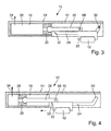
- the Fig. 1 to 28 show a schematic representation of different exemplary embodiments of a device 10 for influencing the opening and / or closing movement of a wing of a door or a window.
- the various devices 10 each comprise a between the wing and a fixed frame arranged (not shown) sliding arm which is rotatably mounted on the one hand on the wing or on the frame and on the other hand guided by a sliding block 12 in a frame or wing arranged slide rail, and in the slide integrated or assigned thereto variably adjustable means 14 for damping the opening movement and / or delaying the closing movement of the wing.
- the means 14 for the opening damping or closing delay comprise a housing 16, a arranged in a receiving space 18 of the housing 16 piston 20 and coupled to the piston 20, cooperating with the sliding block 12 driver 22, which during a predetermined phase of the opening or Closing movement of the wing with the sliding block 12 is engageable.
- the show Fig. 1 to 6 an exemplary embodiment of the device 10, wherein the driver 22 is guided in a slotted guide 24 of the housing 16 so that it is engaged during the predetermined phase of the opening or closing movement of the wing with the sliding block 12 and the sliding block 12 during the remaining opening or closing movement releases.
- the driver 22 is coupled via a piston rod 26 with the piston 20, which is articulated on the one hand on the driver 22 and on the other hand on the piston 20.
- the driver 22 is pivotally connected about an axis 66 with the piston rod 26 and pivotable by the slotted guide 24 about the axis 66 relative to the piston rod 26 to be brought into engagement with the sliding block 12 or release it again.
- the device may be double-acting, that is to be designed both for the opening damping and the closing delay, or even be single-acting, that is, either cause only an opening loss or only a closing delay.
- the piston 20 may be designed to form a respective damping chamber 28 on both sides of the piston without a check valve.
- the piston 20 in particular in a single-acting embodiment of the device 10, the piston 20 to form a damping chamber 28 on one of the two sides of the piston and to form a non-pressurized space on the opposite side of the piston to be provided with a check valve.
- a respective damping chamber 28 may in particular be assigned a throttle valve.
- a throttle valve By means of such a throttle valve, when the damping chamber 28 is acted upon by the piston 20, the medium contained in the damping chamber 28 can be throttled out of the damping chamber 28.
- Fig. 1 shows the device 10 in a phase in which the driver 22 is not yet engaged with the sliding block 12.
- the sliding block 12 hits the driver 22 and is thereby decelerated.
- Fig. 3 shows the device 10 in a Phase in which the extended by the sliding block 12 from a first slotted slope 30 driver 22 is in engagement with the sliding block 12 and the opening damping or closing delay begins.
- Fig. 4 the device 10 is shown in a phase in which the driver 22 moves into a second slotted slope 32 and the opening damping or closing delay is still active.
- Fig. 5 is the device 10 in a phase in which the driven in the second backdrop bevel 32 and corresponding donated driver 22 releases the sliding block 12 again and the opening damping or closing delay ends.
- Fig. 6 shows the device 10 in a phase in which the sliding block 12 is released. As in the Fig. 3 to 5 shown again, during a respective loading of the damping chamber 28 through the piston 20 throttle medium 34 escape from the damping chamber 28.
- the device may also comprise a spring unit (not shown) acting on the driver 22 or piston 20 in order to assist in particular the closing movement of the wing.
- a spring unit acting on the driver 22 or piston 20 in order to assist in particular the closing movement of the wing.
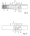
- Fig. 7 to 13 show a schematic representation of another exemplary embodiment of a device 10 according to the invention, this device 10 is provided in the present case with a provision.
- a damping chamber 28 and a particular pressureless space are provided on the opposite sides of the piston 20, wherein in the damping chamber 28, a return spring unit 36 is arranged.
- the return spring unit 36 during the predetermined phase of the opening or closing movement of the wing, in which the driver 22 for opening damping or closing delay is engaged with the sliding block 12 is tensioned to the driver 22 thereafter after the release of the sliding block 12 reset.
- the device 10 can be designed either for opening damping or for closing delay.
- the return spring unit 36 may in particular comprise a compression spring.
- the driver 22 is articulated about an axis 38 pivotally mounted on a guided in the housing 16 slider 40 and provided with a ramp 22, which with a housing fixed stop 44 (see Fig. 10 and 11 ) cooperates to pivot the driver 22 in a release position following the predetermined phase of the opening or closing movement of the wing to release the sliding block 12.
- the stop 44 may comprise, for example, a bolt or the like.
- the driver 22 is coupled via a piston rod 26 with the piston 20, which is articulated on the one hand about an axis 46 pivotally mounted on the slider 4 and on the other hand on the piston 20.
- Fig. 7 shows the device 10 in a phase in which the driver 22 is not yet engaged with the sliding block 12.
- the sliding block 12 hits the driver 22 and is thereby braked, so that the opening damping or closing delay begins.
- the device 10 is reproduced in a phase in which the opening damping or closing delay is active.
- the driver 22 runs on the stop 44.
- Fig. 11 shows the device 10 in a phase in which the driver is pivoted about the axis 38 upwards and releases the sliding block 12, whereby the opening damping or closing delay ends.
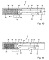
- FIGS. 14 to 26 show a schematic representation of another exemplary embodiment of an inventive device 10.
- this device 10 differs from that in connection with the Fig. 7 to 13 described device 10 at least substantially by the fact that they except the previously described caused by a motion damping closing delay means 48 for additional time delay or brief interruption of the closing movement, by which the opening movement of the wing is temporarily interrupted or stopped.
- the means 48 for additional time delay of the closing movement of the wing a locking wedge 50, of which the sliding block 12 is held after its release by the driver 22 following the predetermined phase of the closing movement of the wing until the arranged in the damping chamber 28 through Return spring unit 36 caused in particular throttled provision of the driver 22 is at least substantially done.
- the locking wedge 50 is displaceable transversely to the direction of movement of the piston 20 in the housing 16 and penetrated by the piston rod 26.
- the piston rod 26 has a portion 52 with a smaller compared to the rest of the piston rod 26 which is aligned at the end of the provision of the driver 22 with the locking wedge 50, so that acted upon by the sliding block 12 locking wedge 50 to release the sliding block 12 from is movable out of his holding position.
- the damping chamber 28 provided on the side of the piston 20 facing away from the piston rod 26 may again be assigned a throttle valve.
- Fig. 14 shows the device 10 in a phase before the wing is opened.
- the device 10 is shown in a phase in which the wing is opened and the sliding block 12 passes over the locking wedge 50.
- Fig. 16 shows the device 10 in a phase in which the wing is opened, after the driver 22 has been run over by the sliding block 12.
- Fig. 17 shows the device 10 in a phase in which the wing is closed, the sliding block 12 meets the driver 22 and is decelerated and the closing delay or damping begins.
- Fig. 18 shows the device 10 in a phase in which the driver 22 on the stopper 44 (see in particular again the Fig. 10 and 11 ) runs up. In this case, throttle medium 34 can flow out of the space 28 receiving the return spring unit 36.
- Fig. 19 the device 10 is reproduced in a phase in which the released by the driver 22 sliding block 12 is held by the locking wedge 50 and the additional time delay or interruption of the closing movement begins.
- Fig. 20 shows the device 10 in a phase in which the sliding block 12 is further held by the locking wedge 50 and the wing remains in the waiting position, and the return spring unit 36, the driver 22 in particular throttles pushed back to its original position.
- throttling medium 34 can flow into the space 28 receiving the return spring unit 36.
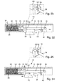
- Fig. 21 shows the locking wedge 50 and this passing through the piston rod 26 of the device 10 according to Fig. 14 in the phase according to Fig. 20 ,
- the locking wedge 50 is not penetrated by the portion 52 of smaller cross-section, but by the greater area having a cross-section remaining portion of the piston rod 26, so that this locking wedge 50 can not escape upwards.
- the return of the driver 22 caused by the return spring unit 36 can in particular be throttled.
- the return speed depends on the throttle strength.
- Fig. 22 shows the device 10 in a phase in which the driver 22 assumes its initial position and the portion 52 of smaller cross-section of the piston rod 26, the locking wedge 50 releases.
- Fig. 23 shows the locking wedge 50 and this passing through the piston rod 26 of the device according to Fig. 14 in the phase according to Fig. 22 , As can be seen from this figure, the locking wedge 50 is penetrated in the present case by the section 52 of smaller cross section of the piston rod 26, so that it can be moved in the housing 16 upwards.
- Fig. 24 shows the device 10 in a phase in which the locking wedge 50 releases the sliding block 12 and the additional time delay or interruption of the closing movement is terminated.
- Fig. 25 shows the locking wedge 50 and this passing through the piston rod 26 of the device 10 according to Fig. 14 in the phase according to Fig. 24 , As can be seen from this figure, the locking wedge is now shifted relative to the piston rod 26 upwards, which was made possible by the relatively smaller cross-section of the portion 52 of the piston rod.
- FIGS. 14 to 26 illustrated device 10 at least substantially the same structure as that in connection with the Fig. 7 to 13 have described device 10.
- Fig. 27 shows a schematic representation of another exemplary embodiment of a device 10 according to the invention for damping the opening movement and / or delaying the closing movement of a wing of a door or a window in which the opening damping or closing delay can be deactivated.
- the driver 22 for deactivating the device 10 for example, by loosening a screw 54 or the like from the piston 20 and the piston rod 26 are released and moved to a neutral position in which he no longer engages with the sliding block 12.
- This loosened screw can, for example, otherwise be plugged into the housing 16 to ensure a Verlierschutz.
- the driver 22 may for example be moved by hand to the neutral position 56.
- the relevant slider 40 can in particular run between the housing 16 and the slide rail. Before the slider 40 is released, the pressure in the housing 16 can be released, for example, by passing over a control bore or a step 58 in the housing, whereupon a sealing ring or the like can be used or a short circuit can be brought about. This avoids unwanted reset by the action of an air spring.
- Fig. 28 shows the device 10 according to Fig. 27 in a phase in which the driver 22 from the sliding block 12 can be driven over, to which the driver 22 may be provided with bevels 60.
- a respective pressure chamber 62 and a regulating valve 64 can be assigned to a respective damping chamber 28 adjacent to the piston 20.
- the regulating valve 64 may, for example, contain open-pored foam which is compressed by a screw or the like.
Landscapes
- Fluid-Damping Devices (AREA)
Applications Claiming Priority (1)
| Application Number | Priority Date | Filing Date | Title |
|---|---|---|---|
| DE102014225291.1A DE102014225291B3 (de) | 2014-12-09 | 2014-12-09 | Vorrichtung zur Beeinflussung der Öffnungs- und/oder Schließbewegung eines Tür- oder Fensterflügels |
Publications (2)
| Publication Number | Publication Date |
|---|---|
| EP3032017A1 true EP3032017A1 (fr) | 2016-06-15 |
| EP3032017B1 EP3032017B1 (fr) | 2019-02-20 |
Family
ID=54251448
Family Applications (1)
| Application Number | Title | Priority Date | Filing Date |
|---|---|---|---|
| EP15187902.0A Active EP3032017B1 (fr) | 2014-12-09 | 2015-10-01 | Dispositif destiné à influencer du mouvement d'ouverture et/ou de fermeture d'un vantail de fenêtre ou battant de porte |
Country Status (2)
| Country | Link |
|---|---|
| EP (1) | EP3032017B1 (fr) |
| DE (1) | DE102014225291B3 (fr) |
Cited By (2)
| Publication number | Priority date | Publication date | Assignee | Title |
|---|---|---|---|---|
| DE102016015376C5 (de) | 2016-12-20 | 2021-11-25 | Wilh. Schlechtendahl & Söhne GmbH & Co. KG | Öffnungsbegrenzungseinrichtung sowie Rahmen-Flügel-Anordnung mit einer solchen |
| CN115142760A (zh) * | 2022-01-23 | 2022-10-04 | 上海臻兆信息技术有限公司 | 一种基于终端互联的智能门控系统 |
Families Citing this family (4)
| Publication number | Priority date | Publication date | Assignee | Title |
|---|---|---|---|---|
| EP3626922A1 (fr) * | 2018-09-19 | 2020-03-25 | dormakaba Deutschland GmbH | Aide à l'actionnement, système d'un palier rotatif et d'au moins une aide à l'actionnement ainsi que procédé de support d'un actionnement de porte manuel à l'aide d'une force auxiliaire au moyen d'au moins une aide à l'actionnement |
| EP3626923A1 (fr) * | 2018-09-19 | 2020-03-25 | dormakaba Deutschland GmbH | Aide à l'actionnement, système d'un actionneur de porte et d'une aide à l'actionnement ainsi que procédé de support d'un actionneur de porte à l'aide d'une force auxiliaire au moyen d'au moins une aide à l'actionnement |
| DE102021214264B4 (de) | 2021-12-13 | 2025-05-22 | Geze Gmbh | Türschließer |
| DE202024101120U1 (de) * | 2024-03-07 | 2024-04-03 | Siegenia-Aubi Kg | Öffnungsbegrenzer |
Citations (5)
| Publication number | Priority date | Publication date | Assignee | Title |
|---|---|---|---|---|
| DE2207106A1 (de) * | 1972-02-16 | 1973-08-23 | M & S Metallwaren Gmbh | Schliesser und hydraulischer schlagdaempfer fuer tueren |
| EP0790381A2 (fr) * | 1995-12-22 | 1997-08-20 | E C O Schulte Gmbh & Co. Kg | Ferme porte à mouvement de fermeture contrÔlé |
| EP1705330A1 (fr) * | 2004-01-13 | 2006-09-27 | K.K. Murakoshi Seikoh | Dispositif amortisseur |
| DE202009016834U1 (de) * | 2009-12-14 | 2010-04-22 | Krischke-Lengersdorf, Christian | Einrichtung zum Dämpfen der Relativbewegung bewegter Vorrichtungsteile, insbesondere von Schiebetüren |
| DE102011087695A1 (de) * | 2011-12-05 | 2013-06-06 | Geze Gmbh | Vorrichtung zur Öffnungsdämpfung eines Flügels einer Tür oder eines Fensters |
Family Cites Families (2)
| Publication number | Priority date | Publication date | Assignee | Title |
|---|---|---|---|---|
| DE3604091A1 (de) * | 1986-02-08 | 1987-08-13 | Dorma Gmbh & Co Kg | Schliessfolgeregelvorrichtung fuer eine zweifluegelige tuer |
| DE102008056214B4 (de) * | 2008-11-06 | 2014-09-25 | Assa Abloy Sicherheitstechnik Gmbh | Arretiereinheit für einen Türschließer, Türschließsystem, Verwendung einer Arretiereinheit und Verfahren zum Arretieren einer Tür |
-
2014
- 2014-12-09 DE DE102014225291.1A patent/DE102014225291B3/de active Active
-
2015
- 2015-10-01 EP EP15187902.0A patent/EP3032017B1/fr active Active
Patent Citations (5)
| Publication number | Priority date | Publication date | Assignee | Title |
|---|---|---|---|---|
| DE2207106A1 (de) * | 1972-02-16 | 1973-08-23 | M & S Metallwaren Gmbh | Schliesser und hydraulischer schlagdaempfer fuer tueren |
| EP0790381A2 (fr) * | 1995-12-22 | 1997-08-20 | E C O Schulte Gmbh & Co. Kg | Ferme porte à mouvement de fermeture contrÔlé |
| EP1705330A1 (fr) * | 2004-01-13 | 2006-09-27 | K.K. Murakoshi Seikoh | Dispositif amortisseur |
| DE202009016834U1 (de) * | 2009-12-14 | 2010-04-22 | Krischke-Lengersdorf, Christian | Einrichtung zum Dämpfen der Relativbewegung bewegter Vorrichtungsteile, insbesondere von Schiebetüren |
| DE102011087695A1 (de) * | 2011-12-05 | 2013-06-06 | Geze Gmbh | Vorrichtung zur Öffnungsdämpfung eines Flügels einer Tür oder eines Fensters |
Cited By (2)
| Publication number | Priority date | Publication date | Assignee | Title |
|---|---|---|---|---|
| DE102016015376C5 (de) | 2016-12-20 | 2021-11-25 | Wilh. Schlechtendahl & Söhne GmbH & Co. KG | Öffnungsbegrenzungseinrichtung sowie Rahmen-Flügel-Anordnung mit einer solchen |
| CN115142760A (zh) * | 2022-01-23 | 2022-10-04 | 上海臻兆信息技术有限公司 | 一种基于终端互联的智能门控系统 |
Also Published As
| Publication number | Publication date |
|---|---|
| DE102014225291B3 (de) | 2015-12-24 |
| EP3032017B1 (fr) | 2019-02-20 |
Similar Documents
| Publication | Publication Date | Title |
|---|---|---|
| EP3032017B1 (fr) | Dispositif destiné à influencer du mouvement d'ouverture et/ou de fermeture d'un vantail de fenêtre ou battant de porte | |
| DE102014212863A1 (de) | Antriebsanordnung und Klappensteuerung | |
| DE102009017342A1 (de) | Weit öffnende Fahrzeugtür mit Zugriffserleichterungsmerkmal | |
| EP3004504B1 (fr) | Ferme-porte pour un vantail de porte ou de fenetre | |
| DE202008005721U1 (de) | Türschließer mit einer hydraulischen Schließverzögerung | |
| WO2022082238A1 (fr) | Dispositif d'entraînement pour une partie de meuble mobile | |
| DE102010008167B4 (de) | Schieberventil eines Türbetätigers | |
| DE102016208099B4 (de) | Antrieb für eine tür | |
| EP2679756B1 (fr) | Entraînement destiné à ouvrir et/ou fermer un battant mobile d'une porte ou d'une fenêtre et procédé de fonctionnement de cet entraînement | |
| EP3032018B1 (fr) | Dispositif de rétraction | |
| DE102018210277B4 (de) | Ventil | |
| EP3070246A1 (fr) | Dispositif de retenue pour un battant de porte pivotant | |
| EP3156574A1 (fr) | Systeme dote d'une porte coulissante et d'une partie fixe, sur laquelle la porte coulissante peut etre deplacee | |
| DE102016100956A1 (de) | Türantrieb mit Haupt- und Hilfsantrieb und Zusatzfunktionskomponenten | |
| DE10361085B4 (de) | Hydraulisch-mechanische Schließfolgeregelung | |
| DE102016211149B4 (de) | Vorrichtung zum Offenhalten eines Tür- oder Fensterflügels | |
| EP2735681A2 (fr) | Entraînement pour un battant de porte ou de fenêtre | |
| EP2784258A2 (fr) | Dispositif de fermeture pour un vantail d'une porte ou d'une fenêtre | |
| EP1620626B2 (fr) | Sequence de fermeture mecano-hydraulique | |
| EP1609936A2 (fr) | Dispositif pour limitation d'un ouvrant de porte ou de fenêtre | |
| EP2913469B1 (fr) | Régulation de la séquence de fermeture pour une porte comprenant un battant fixe et un battant mobile | |
| EP1544397A2 (fr) | Dispositif d'arrêt d'une aile de porte ou de fenêtre | |
| DE102018210276B4 (de) | Ventil | |
| EP2811097B1 (fr) | Entraînement pour un battant de porte ou de fenêtre | |
| DE102016002110A1 (de) | Dämpfungseinrichtung für einen parallel verschiebbaren Flügel als Schiebekippflügel oder Schiebeflügel |
Legal Events
| Date | Code | Title | Description |
|---|---|---|---|
| PUAI | Public reference made under article 153(3) epc to a published international application that has entered the european phase |
Free format text: ORIGINAL CODE: 0009012 |
|
| AK | Designated contracting states |
Kind code of ref document: A1 Designated state(s): AL AT BE BG CH CY CZ DE DK EE ES FI FR GB GR HR HU IE IS IT LI LT LU LV MC MK MT NL NO PL PT RO RS SE SI SK SM TR |
|
| AX | Request for extension of the european patent |
Extension state: BA ME |
|
| STAA | Information on the status of an ep patent application or granted ep patent |
Free format text: STATUS: REQUEST FOR EXAMINATION WAS MADE |
|
| 17P | Request for examination filed |
Effective date: 20161214 |
|
| RBV | Designated contracting states (corrected) |
Designated state(s): AL AT BE BG CH CY CZ DE DK EE ES FI FR GB GR HR HU IE IS IT LI LT LU LV MC MK MT NL NO PL PT RO RS SE SI SK SM TR |
|
| STAA | Information on the status of an ep patent application or granted ep patent |
Free format text: STATUS: EXAMINATION IS IN PROGRESS |
|
| 17Q | First examination report despatched |
Effective date: 20171102 |
|
| GRAP | Despatch of communication of intention to grant a patent |
Free format text: ORIGINAL CODE: EPIDOSNIGR1 |
|
| STAA | Information on the status of an ep patent application or granted ep patent |
Free format text: STATUS: GRANT OF PATENT IS INTENDED |
|
| INTG | Intention to grant announced |
Effective date: 20180720 |
|
| GRAS | Grant fee paid |
Free format text: ORIGINAL CODE: EPIDOSNIGR3 |
|
| RBV | Designated contracting states (corrected) |
Designated state(s): AL AT BE BG CH CY CZ DK EE ES FI FR GB GR HR HU IE IS IT LI LT LU LV MC MK MT NL NO PL PT RO RS SE SI SK SM TR |
|
| REG | Reference to a national code |
Ref country code: DE Ref legal event code: R108 |
|
| GRAA | (expected) grant |
Free format text: ORIGINAL CODE: 0009210 |
|
| STAA | Information on the status of an ep patent application or granted ep patent |
Free format text: STATUS: THE PATENT HAS BEEN GRANTED |
|
| AK | Designated contracting states |
Kind code of ref document: B1 Designated state(s): AL AT BE BG CH CY CZ DK EE ES FI FR GB GR HR HU IE IS IT LI LT LU LV MC MK MT NL NO PL PT RO RS SE SI SK SM TR |
|
| REG | Reference to a national code |
Ref country code: GB Ref legal event code: FG4D Free format text: NOT ENGLISH |
|
| REG | Reference to a national code |
Ref country code: CH Ref legal event code: EP |
|
| REG | Reference to a national code |
Ref country code: AT Ref legal event code: REF Ref document number: 1098397 Country of ref document: AT Kind code of ref document: T Effective date: 20190315 |
|
| REG | Reference to a national code |
Ref country code: IE Ref legal event code: FG4D Free format text: LANGUAGE OF EP DOCUMENT: GERMAN |
|
| REG | Reference to a national code |
Ref country code: NL Ref legal event code: MP Effective date: 20190220 |
|
| REG | Reference to a national code |
Ref country code: LT Ref legal event code: MG4D |
|
| PG25 | Lapsed in a contracting state [announced via postgrant information from national office to epo] |
Ref country code: NL Free format text: LAPSE BECAUSE OF FAILURE TO SUBMIT A TRANSLATION OF THE DESCRIPTION OR TO PAY THE FEE WITHIN THE PRESCRIBED TIME-LIMIT Effective date: 20190220 Ref country code: LT Free format text: LAPSE BECAUSE OF FAILURE TO SUBMIT A TRANSLATION OF THE DESCRIPTION OR TO PAY THE FEE WITHIN THE PRESCRIBED TIME-LIMIT Effective date: 20190220 Ref country code: SE Free format text: LAPSE BECAUSE OF FAILURE TO SUBMIT A TRANSLATION OF THE DESCRIPTION OR TO PAY THE FEE WITHIN THE PRESCRIBED TIME-LIMIT Effective date: 20190220 Ref country code: FI Free format text: LAPSE BECAUSE OF FAILURE TO SUBMIT A TRANSLATION OF THE DESCRIPTION OR TO PAY THE FEE WITHIN THE PRESCRIBED TIME-LIMIT Effective date: 20190220 Ref country code: NO Free format text: LAPSE BECAUSE OF FAILURE TO SUBMIT A TRANSLATION OF THE DESCRIPTION OR TO PAY THE FEE WITHIN THE PRESCRIBED TIME-LIMIT Effective date: 20190520 Ref country code: PT Free format text: LAPSE BECAUSE OF FAILURE TO SUBMIT A TRANSLATION OF THE DESCRIPTION OR TO PAY THE FEE WITHIN THE PRESCRIBED TIME-LIMIT Effective date: 20190620 |
|
| PG25 | Lapsed in a contracting state [announced via postgrant information from national office to epo] |
Ref country code: GR Free format text: LAPSE BECAUSE OF FAILURE TO SUBMIT A TRANSLATION OF THE DESCRIPTION OR TO PAY THE FEE WITHIN THE PRESCRIBED TIME-LIMIT Effective date: 20190521 Ref country code: BG Free format text: LAPSE BECAUSE OF FAILURE TO SUBMIT A TRANSLATION OF THE DESCRIPTION OR TO PAY THE FEE WITHIN THE PRESCRIBED TIME-LIMIT Effective date: 20190520 Ref country code: HR Free format text: LAPSE BECAUSE OF FAILURE TO SUBMIT A TRANSLATION OF THE DESCRIPTION OR TO PAY THE FEE WITHIN THE PRESCRIBED TIME-LIMIT Effective date: 20190220 Ref country code: RS Free format text: LAPSE BECAUSE OF FAILURE TO SUBMIT A TRANSLATION OF THE DESCRIPTION OR TO PAY THE FEE WITHIN THE PRESCRIBED TIME-LIMIT Effective date: 20190220 Ref country code: LV Free format text: LAPSE BECAUSE OF FAILURE TO SUBMIT A TRANSLATION OF THE DESCRIPTION OR TO PAY THE FEE WITHIN THE PRESCRIBED TIME-LIMIT Effective date: 20190220 Ref country code: IS Free format text: LAPSE BECAUSE OF FAILURE TO SUBMIT A TRANSLATION OF THE DESCRIPTION OR TO PAY THE FEE WITHIN THE PRESCRIBED TIME-LIMIT Effective date: 20190620 |
|
| PG25 | Lapsed in a contracting state [announced via postgrant information from national office to epo] |
Ref country code: SK Free format text: LAPSE BECAUSE OF FAILURE TO SUBMIT A TRANSLATION OF THE DESCRIPTION OR TO PAY THE FEE WITHIN THE PRESCRIBED TIME-LIMIT Effective date: 20190220 Ref country code: RO Free format text: LAPSE BECAUSE OF FAILURE TO SUBMIT A TRANSLATION OF THE DESCRIPTION OR TO PAY THE FEE WITHIN THE PRESCRIBED TIME-LIMIT Effective date: 20190220 Ref country code: CZ Free format text: LAPSE BECAUSE OF FAILURE TO SUBMIT A TRANSLATION OF THE DESCRIPTION OR TO PAY THE FEE WITHIN THE PRESCRIBED TIME-LIMIT Effective date: 20190220 Ref country code: ES Free format text: LAPSE BECAUSE OF FAILURE TO SUBMIT A TRANSLATION OF THE DESCRIPTION OR TO PAY THE FEE WITHIN THE PRESCRIBED TIME-LIMIT Effective date: 20190220 Ref country code: AL Free format text: LAPSE BECAUSE OF FAILURE TO SUBMIT A TRANSLATION OF THE DESCRIPTION OR TO PAY THE FEE WITHIN THE PRESCRIBED TIME-LIMIT Effective date: 20190220 Ref country code: EE Free format text: LAPSE BECAUSE OF FAILURE TO SUBMIT A TRANSLATION OF THE DESCRIPTION OR TO PAY THE FEE WITHIN THE PRESCRIBED TIME-LIMIT Effective date: 20190220 Ref country code: DK Free format text: LAPSE BECAUSE OF FAILURE TO SUBMIT A TRANSLATION OF THE DESCRIPTION OR TO PAY THE FEE WITHIN THE PRESCRIBED TIME-LIMIT Effective date: 20190220 |
|
| PG25 | Lapsed in a contracting state [announced via postgrant information from national office to epo] |
Ref country code: SM Free format text: LAPSE BECAUSE OF FAILURE TO SUBMIT A TRANSLATION OF THE DESCRIPTION OR TO PAY THE FEE WITHIN THE PRESCRIBED TIME-LIMIT Effective date: 20190220 Ref country code: PL Free format text: LAPSE BECAUSE OF FAILURE TO SUBMIT A TRANSLATION OF THE DESCRIPTION OR TO PAY THE FEE WITHIN THE PRESCRIBED TIME-LIMIT Effective date: 20190220 |
|
| PLBE | No opposition filed within time limit |
Free format text: ORIGINAL CODE: 0009261 |
|
| STAA | Information on the status of an ep patent application or granted ep patent |
Free format text: STATUS: NO OPPOSITION FILED WITHIN TIME LIMIT |
|
| 26N | No opposition filed |
Effective date: 20191121 |
|
| PG25 | Lapsed in a contracting state [announced via postgrant information from national office to epo] |
Ref country code: SI Free format text: LAPSE BECAUSE OF FAILURE TO SUBMIT A TRANSLATION OF THE DESCRIPTION OR TO PAY THE FEE WITHIN THE PRESCRIBED TIME-LIMIT Effective date: 20190220 |
|
| PG25 | Lapsed in a contracting state [announced via postgrant information from national office to epo] |
Ref country code: TR Free format text: LAPSE BECAUSE OF FAILURE TO SUBMIT A TRANSLATION OF THE DESCRIPTION OR TO PAY THE FEE WITHIN THE PRESCRIBED TIME-LIMIT Effective date: 20190220 |
|
| PG25 | Lapsed in a contracting state [announced via postgrant information from national office to epo] |
Ref country code: MC Free format text: LAPSE BECAUSE OF FAILURE TO SUBMIT A TRANSLATION OF THE DESCRIPTION OR TO PAY THE FEE WITHIN THE PRESCRIBED TIME-LIMIT Effective date: 20190220 |
|
| REG | Reference to a national code |
Ref country code: CH Ref legal event code: PL |
|
| PG25 | Lapsed in a contracting state [announced via postgrant information from national office to epo] |
Ref country code: LU Free format text: LAPSE BECAUSE OF NON-PAYMENT OF DUE FEES Effective date: 20191001 Ref country code: CH Free format text: LAPSE BECAUSE OF NON-PAYMENT OF DUE FEES Effective date: 20191031 Ref country code: LI Free format text: LAPSE BECAUSE OF NON-PAYMENT OF DUE FEES Effective date: 20191031 |
|
| REG | Reference to a national code |
Ref country code: BE Ref legal event code: MM Effective date: 20191031 |
|
| PG25 | Lapsed in a contracting state [announced via postgrant information from national office to epo] |
Ref country code: BE Free format text: LAPSE BECAUSE OF NON-PAYMENT OF DUE FEES Effective date: 20191031 |
|
| PG25 | Lapsed in a contracting state [announced via postgrant information from national office to epo] |
Ref country code: IE Free format text: LAPSE BECAUSE OF NON-PAYMENT OF DUE FEES Effective date: 20191001 |
|
| PG25 | Lapsed in a contracting state [announced via postgrant information from national office to epo] |
Ref country code: CY Free format text: LAPSE BECAUSE OF FAILURE TO SUBMIT A TRANSLATION OF THE DESCRIPTION OR TO PAY THE FEE WITHIN THE PRESCRIBED TIME-LIMIT Effective date: 20190220 |
|
| PG25 | Lapsed in a contracting state [announced via postgrant information from national office to epo] |
Ref country code: HU Free format text: LAPSE BECAUSE OF FAILURE TO SUBMIT A TRANSLATION OF THE DESCRIPTION OR TO PAY THE FEE WITHIN THE PRESCRIBED TIME-LIMIT; INVALID AB INITIO Effective date: 20151001 Ref country code: MT Free format text: LAPSE BECAUSE OF FAILURE TO SUBMIT A TRANSLATION OF THE DESCRIPTION OR TO PAY THE FEE WITHIN THE PRESCRIBED TIME-LIMIT Effective date: 20190220 |
|
| REG | Reference to a national code |
Ref country code: AT Ref legal event code: MM01 Ref document number: 1098397 Country of ref document: AT Kind code of ref document: T Effective date: 20201001 |
|
| PG25 | Lapsed in a contracting state [announced via postgrant information from national office to epo] |
Ref country code: AT Free format text: LAPSE BECAUSE OF NON-PAYMENT OF DUE FEES Effective date: 20201001 |
|
| PG25 | Lapsed in a contracting state [announced via postgrant information from national office to epo] |
Ref country code: MK Free format text: LAPSE BECAUSE OF FAILURE TO SUBMIT A TRANSLATION OF THE DESCRIPTION OR TO PAY THE FEE WITHIN THE PRESCRIBED TIME-LIMIT Effective date: 20190220 |
|
| P01 | Opt-out of the competence of the unified patent court (upc) registered |
Effective date: 20230510 |
|
| PGFP | Annual fee paid to national office [announced via postgrant information from national office to epo] |
Ref country code: GB Payment date: 20251022 Year of fee payment: 11 |
|
| PGFP | Annual fee paid to national office [announced via postgrant information from national office to epo] |
Ref country code: IT Payment date: 20251024 Year of fee payment: 11 |
|
| PGFP | Annual fee paid to national office [announced via postgrant information from national office to epo] |
Ref country code: FR Payment date: 20251030 Year of fee payment: 11 |