EP3045601A1 - Construction à poteaux-traverses - Google Patents
Construction à poteaux-traverses Download PDFInfo
- Publication number
- EP3045601A1 EP3045601A1 EP15202938.5A EP15202938A EP3045601A1 EP 3045601 A1 EP3045601 A1 EP 3045601A1 EP 15202938 A EP15202938 A EP 15202938A EP 3045601 A1 EP3045601 A1 EP 3045601A1
- Authority
- EP
- European Patent Office
- Prior art keywords
- insulating element
- insulating
- construction according
- filling elements
- mullion
- Prior art date
- Legal status (The legal status is an assumption and is not a legal conclusion. Google has not performed a legal analysis and makes no representation as to the accuracy of the status listed.)
- Granted
Links
Images





Classifications
-
- E—FIXED CONSTRUCTIONS
- E04—BUILDING
- E04B—GENERAL BUILDING CONSTRUCTIONS; WALLS, e.g. PARTITIONS; ROOFS; FLOORS; CEILINGS; INSULATION OR OTHER PROTECTION OF BUILDINGS
- E04B2/00—Walls, e.g. partitions, for buildings; Wall construction with regard to insulation; Connections specially adapted to walls
- E04B2/88—Curtain walls
- E04B2/96—Curtain walls comprising panels attached to the structure through mullions or transoms
- E04B2/967—Details of the cross-section of the mullions or transoms
Definitions
- the present invention relates to a mullion and transom construction, in particular for facades, skylights or pitched roofs, with a support profile on which two filling elements are peripherally held on sealing strips, wherein in a space between opposite end faces of the filling elements, a strip-shaped insulating member is arranged.
- the DE 203 18 083 U1 discloses a mullion and transom construction in which a respective screw channel is formed on the support profiles.
- a respective screw channel is formed on the support profiles.
- an insulating strip is inserted, which extends between the end faces of two filling elements.
- the thermal insulation can be improved by the insulating strip, but can be obtained by the protruding screw only limited a compact design.
- the screw groove of the support profile can not be used for other purposes, since this is needed for fixing the insulating strip and screws for a pressure strip.
- the DE 296 11 109 U1 discloses a steel-glass facade in which laminated glass panes are fixed via sliding blocks and bolts. To each bolt in two corner areas, a glass holder is provided, the area between the glass holders is not isolated, so that only a small thermal insulation can be achieved.
- a post-and-bolt arrangement in which a plurality of holders are inserted at a groove of a profile part.
- the holders are used for prefixing a strip-shaped insulating body, which is attached to the holder.
- additional fastening means are needed, which are fixed to the groove of the profile part and are introduced from the outside through the insulating body.
- the post-and-bolt arrangement requires comparatively many components, which makes the assembly complex.
- the strip-shaped insulating element is plugged or pushed through at least one bolt.
- the fixing of the insulating element is no longer on a screw, so that this area can be used on the support section for other functions.
- the installation of the insulating element can be done simply by plugging on one or more bolts, so that a prefixing is achieved.
- the insulating element is arranged protected anyway and exposed only to low forces.
- the at least one bolt passes through the insulating element.
- the insulating member may be formed closed prior to assembly, so that an opening is made only by attaching the insulating member to the bolt, allowing flexible adaptation to different distances from the bolt.
- the insulating element is attached to a plurality of bolts, so that the insulating is securely held on the bolt, before then the final assembly is done with the pressure bar.
- the bolt can be designed as a pin, a threaded bolt, a prismatic body with and without undercut or as a screw.
- a groove is formed on the support profile into which a head connected to the bolt is slidably inserted in order to fix a retaining strip in a clamping manner on an outer side of the filling elements.
- the bolts can protrude between the filling elements, so that during assembly, the insulating element can be easily attached to the bolt. The bolts penetrate into the insulating element, but can penetrate it.
- the insulating element extends from an outer side of the filling elements to an inner side.
- the insulating member may comprise at least one web which extends completely from the outer to the inside of the filling elements, whereby a shorter design of the insulating is possible, which does not extend completely from the outer to the inside.
- At the bridge can be at least one projection in the direction be provided the end face of the filling element, so that the gap between the insulating element and an end face of the filling element is divided into one or more chambers, even if the projection does not touch the front page. For even the reduction of air circulation and air flow in the gap between insulating and front side of the filling element can have a positive effect in terms of thermal insulation.
- the insulating element has two parallel webs which extend in the direction from an outer side to an inner side of the filling elements.
- the bolt is preferably carried out between the two webs, so that the webs have a guiding function during assembly.
- the webs can for this purpose also consist of a harder material than a filling material between the webs, so that when plugging the insulating the softer filling material can be easily displaced by the bolt, the harder webs but assume a leadership function.
- One or more filled chambers can also be provided on the insulating element.
- materials for different functions can be arranged, on the one hand for thermal insulation and on the other hand as a drainage channel or for fire protection.
- a chamber may be filled with a material that foams under heat.
- the pin or the pin or the screw can also be attached to the pressure bar and the pressure bar including strip-shaped insulating are mounted.
- the strip-shaped insulating element and the pressure strip with the fastening means form a preassembled unit, which is then fixed to the support profile with the filling elements.
- one or more sliding blocks are then mounted to the middle groove, in which then the fasteners or bolts are mounted on the pressure bar.
- an insulating element for a mullion and transom construction is also provided. With the insulating existing post and beam structures can also be retrofitted.
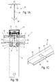
- a mullion and transom construction 1 comprises a support profile 2, which may be formed as a post or latch and has on one side a first groove 3 and a second groove 4 for receiving in each case a sealing strip 6. Between the grooves 3 and 4, a central groove 5 is formed, in which a head 9 of a bolt 8 is inserted. Over the length of the groove 5, a plurality of bolts 8 can be arranged at certain intervals.
- the support profile 2 is used to define two filling elements 7, which may be formed in particular as insulating glass panes.
- the insulating glass panes lie on each edge on a sealing strip 6 on the side facing the support profile 2 side and are fixed at the opposite side by a sealing strip 13 by clamping.
- two sealing strips 13 are held on the outside on a retaining strip 10 and the retaining strip 10 is biased to the support section 2 out.
- threads are provided on the bolt 8 on the outside, on each of which a nut 11 is turned on.
- insulating glass panes can be used, wherein in FIG. 1B two glass sheets 70 are spaced apart on the edge by a spacer 71. It is also possible to use insulating glass panes with more than two glass panes 70.
- the insulating element 20 consists of an insulating material, in particular of plastic, an elastomer, a foamed plastic or other materials and comprises a web 21 which extends substantially parallel to the end faces of the filling elements 7.
- the web 21 On the web 21, two protruding arms 22 are integrally formed on the outside, which abut with a bottom on an outer side of the filling elements 7.
- a facing to the filling elements 7 surface 23 may be coated with adhesive, but may also be free of adhesive.
- the adhesive may be provided with reflective agents such as a reflective foil.
- V-shaped projection 24 On the opposite inside of the insulating a cross-sectionally V-shaped projection 24 is formed, which extends to near the end face of the two filling elements 7.
- V-shaped projection 24 By the V-shaped projection 24, a gap between the web 21 and an end face of a filling element 7 is divided into two chambers, which improves the thermal insulation. It is also possible to provide on the web 21 a plurality of projections 24 which extend in the direction of the end face of the filling elements 7.
- the strip-shaped insulating member 20 is attached to the bolt 8, wherein accordingly Figure 1C 22 openings 25 are provided for performing a bolt 8 centrally on the arms.
- the openings 25 may be provided at regular intervals. In the area of the openings 25 is no web 21, but only a recess 26, so that the bolt 8 can be positioned in the recess 26 between the webs 21.
- the material of the insulating member 7 may be selected so that when plugging an opening for performing the bolt 8 in the arms 22 and the web 21 is generated.
- the insulating member 7 is additionally fixed by the arms 22, which are clamped between the sealing strips 13 and the outside of the filling elements 7.
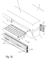
- FIG. 1D the mullion-transom construction 1 is shown during assembly.
- the filling elements 7 rest on the sealing strips 6 on the support profile 2. Between the two filling elements 7 are bolts 8 with a threaded portion, on which the retaining strip 10 is attached with slots 12.
- FIG. 1D shown insulating member 20 'is slightly modified from the insulating member 20 and additionally has on the web 21 further projections 24, which divide the space between the web 21 and an end face of the filling element 7 into individual chambers.
- the insulating member 20 ' is divided into individual sections for mounting, which are each mounted between two bolts 8 and thereby plugged onto the bolt 8, in which each section is clamped between the bolts 8.
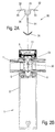
- the mullion and transom construction 1 is formed substantially identical to the support profile 2 and only one other insulating element is used. Therefore, the same components have been given the same reference numerals, and only the insulating member will be explained below with priority.
- a modified insulating member 30 is installed on a mullion-and-transom structure 1 including a ridge 31 extending parallel to the end faces of the filling members 7.
- the strip-shaped insulating member 30 is not T-shaped as in Figure 1A but only with two substantially perpendicularly projecting from the web 21 arms 32, between which a groove 35 is formed.
- the arms 32 may rest with a bottom 33 on the outside of the filling elements 7.
- the groove 35 serves with the preferred V-shaped contour serves the Screw guide in areas where no bolts are engaged.
- the web 31 is provided with a recess 37 which extends to the bottom of the groove 35, to which an opening 38 is provided.
- the insulating member 30 On the opposite inner side, the insulating member 30 has two V-shaped projections 34, which are formed of a different material than the web 31, in particular a softer material which is bendable. As a result, with tolerances with regard to the spacing of the filling elements 7, bending of the projections 34 can take place.
- a plurality of projections 34 may be integrally formed on the web 31.
- the insulating member 30 is again attached to the bolt 8, wherein the groove 35 can serve as an assembly aid to perform an end portion of the bolt 8 between the two arms 32 at the opening 38.
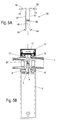
- FIG. 3A there is shown a modified insulating member 40 having two spaced lands 41 extending substantially parallel to an end face of the filling elements 7.
- the two webs 41 are each provided on the outside with a laterally projecting arm 42 which can be clamped between a sealing strip 13 and the outside of a filling element 7.
- a filling element 46 in the form of a connecting web is provided on the outside, wherein the connecting web can optionally be made of the same material as the webs 41 or of a softer material.
- the use of a softer material leads to the advantage that the insulating element can be easily attached to the bolt 8, since the filling element 46 must be pierced when plugging.
- the bolt 8 can then be guided in a gap 45 between the two webs 41.
- a filling material or one or more connecting webs may be provided in the intermediate space 45.
- Each web 41 has on the inside on the side facing the support section 2 an outwardly projecting projection 44 which projects to an end face of the filling element 7 and thus makes a subdivision of the intermediate space into individual chambers, even if these chambers are not completely separated from each other have to.
- the projections 44 may be made of the same material as the webs 41 or of a softer material.
- An underside 43 of the arms 42 can optionally also be coated with adhesive, but for the fixation it suffices to fasten the bolt 8 without the arms 42 having to be glued.
- FIG. 4A a further embodiment of an insulating element 50 is shown in which only one web 51 extends substantially parallel to the end face of the filling elements 7.
- the web 51 is no longer arranged centrally between the filling elements 7, as in the FIGS. 1 and 2 the case was, but off-center.
- a first arm 52 protrudes substantially perpendicularly, which rests with a lower side 53 on the outside of a filling element 7.
- a second shorter arm 54 protrudes on the opposite side and rests with a bottom 55 on the outside of the filling element 7.
- two projections 56 and 57 are integrally formed on the web, which preferably consist of a softer material than the web 51, wherein the projection 56 is formed longer than the projection 57.
- FIG. 5A a further insulating element 60 is shown that has two webs 61 which extend substantially parallel to the end face of the filling elements 7.
- the webs 61 are not completely straight, but slightly curved inward in the outer region.
- each web 61 is provided in the outside with an arm 62 protruding to the filling element 7, which rests with a bottom 63 on the filling element 7.
- On the inside of each web 61 is provided with a projection 64 which protrudes toward the end face of the filling elements 7.
- the webs 61 are held together by an elastic connecting web 66, which is W-shaped. Other geometries of connecting webs are of course possible.
- FIG. 6A a further insulating member 80 is shown having two outwardly projecting arms 81 having an underside 82 on the outside of a Lying filling element.
- this insulating member 80 no linear web is provided, but in the space between adjacent filling elements 7 balloon-shaped chambers 83, 84, 85 and 86 are provided, which are filled with different materials.
- a V-shaped projection 87 is formed, the webs of which extend at least obliquely to the end face of the filling elements 7.
- insulating ribs 88 are further provided, which are also provided with small projections 89 to divide the space between the end face of the filling elements 7 and the insulating web 88 into smaller chambers, which improves the thermal insulation.
- the chambers 83-86 are filled with materials that can perform various functions.
- one of the chambers may be filled with a material that foams under the action of heat and thus seals a seal of the intermediate space between the filling elements 7 in case of fire.
- one of the chambers can also be used for removing moisture or for other purposes.
- FIG. 7A a further insulating member 90 is shown that substantially the insulating member 80 of the FIG. 6a corresponds without the balloon-shaped chambers 93 are provided with a filling material.
- the Isolierstege 88 and 89 were omitted.
- the balloon-shaped chambers 93 are connected on one side with a V-shaped projection 94 and on the opposite outer side with protruding arms 91 which rest with a bottom 92 on the outside of the filling elements 7.
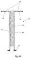
- FIG 8A another strip-shaped insulating element 100 is shown, which has two spaced webs 101, both of which extend substantially parallel to an end face of the filling elements 7. Between the webs 101 at least one filling material 104 is arranged, for example a foamed material which can be easily pierced by the bolts 8 during assembly. When using several layers of a filling material, the layers of filling material 104 may be positioned in parallel or orthogonal alignment with the web of web 101 and sandwiched. There may be hollow chambers between the individual layers of the filling materials, wherein the layer structure can also begin with a material-free area.
- a foamed material which can be easily pierced by the bolts 8 during assembly.
- the webs 101 are made of a harder material than the filling material 104 and can guide the bolt 8 from the inside to the outside.
- a substantially rectangular protruding arm 102 is integrally formed on the outside, which rests with an underside 103 on an outer side of a filling element 7 '.
- an outwardly projecting projection 105 On the inside of each web 101 is provided with an outwardly projecting projection 105, which may preferably consist of a softer material than the webs 101 and serves to improve the thermal insulation. It is also possible to provide a plurality of projections 105 on the web 101.
- FIG. 8B the installation situation of the insulating element 100 is shown that is arranged substantially between two filling elements 7 ', which are formed as insulating glass panes with three glass panes 70.
- the filling material 104 is penetrated by a plurality of bolts 8, which are mounted at certain intervals on a groove 5 of the support profile 2.
- the projections 105 extend to an end face of the filling element 7 'and serves to improve the thermal insulation, wherein a plurality of projections 105 may be provided on the webs 101.
- the insulating elements 20, 30, 40, 50, 60, 80, 90, 100 extend substantially completely from an outer side to an inner side of the filling elements 7 or 7 '. It is of course also possible that the insulating elements are slightly shorter than the end face of the filling elements 7 or 7 'are formed or even longer. Good thermal insulation is obtained when the insulating elements 20, 30, 40, 50, 60, 80, 90, 100 extend at least over 50%, preferably over at least 80%, of the length between the inside and outside of the filling elements. It is also possible that the length of the insulating elements is greater than the distance between the inside and outside of the filling elements, for example, the insulating elements can also extend to the surface of the groove 5.
- FIGS. 1 to 8 can be combined with one another in many areas.
- an insulating element with a web 21, 31, 41, 51, 61, 101 are additionally provided with balloon-shaped chambers 83, 84, 85, 86 or 93 or the web can be provided with one or more of these chambers.
- each projection 105, 56, 57 may also be useful to coat or bond each projection 105, 56, 57 but also each web 101 with a reflective material.
Landscapes
- Engineering & Computer Science (AREA)
- Architecture (AREA)
- Physics & Mathematics (AREA)
- Electromagnetism (AREA)
- Civil Engineering (AREA)
- Structural Engineering (AREA)
- Load-Bearing And Curtain Walls (AREA)
- Securing Of Glass Panes Or The Like (AREA)
Applications Claiming Priority (1)
| Application Number | Priority Date | Filing Date | Title |
|---|---|---|---|
| DE102015100526.3A DE102015100526A1 (de) | 2015-01-14 | 2015-01-14 | Pfosten-Riegel-Konstruktion |
Publications (2)
| Publication Number | Publication Date |
|---|---|
| EP3045601A1 true EP3045601A1 (fr) | 2016-07-20 |
| EP3045601B1 EP3045601B1 (fr) | 2021-04-14 |
Family
ID=55027523
Family Applications (1)
| Application Number | Title | Priority Date | Filing Date |
|---|---|---|---|
| EP15202938.5A Active EP3045601B1 (fr) | 2015-01-14 | 2015-12-29 | Construction à poteaux-traverses |
Country Status (2)
| Country | Link |
|---|---|
| EP (1) | EP3045601B1 (fr) |
| DE (1) | DE102015100526A1 (fr) |
Families Citing this family (1)
| Publication number | Priority date | Publication date | Assignee | Title |
|---|---|---|---|---|
| DE102024126268A1 (de) * | 2024-09-12 | 2026-03-12 | Hydro Extruded Solutions As | Brandschutzeinlage für den Montagestoß im Trennungsbereich von zwei aneinandergrenzenden Pfosten einer Pfosten-Riegel-Konstruktion |
Citations (7)
| Publication number | Priority date | Publication date | Assignee | Title |
|---|---|---|---|---|
| GB2159202A (en) * | 1984-05-24 | 1985-11-27 | Schuermann & Co Heinz | Prefabricated facade |
| DE3742723C1 (en) * | 1987-12-17 | 1988-09-15 | Wieland Werke Ag | Frame structure by the post/crossmember construction method, in particular for facades, roofs or the like |
| DE29611109U1 (de) | 1996-06-25 | 1996-12-12 | Kunad, Günther, Prof. Dr., 39110 Magdeburg | Stahl-Glas-Fassade |
| EP1170455A1 (fr) * | 2000-07-07 | 2002-01-09 | Technal | Joint d'étanchéité pour facade du type à mur rideau. |
| DE20318083U1 (de) | 2003-11-22 | 2004-02-12 | SCHÜCO International KG | Dichtelement zum Belüften und Entwässern von Fassadenkonstruktionen oder Lichtdächern |
| DE102012104000B4 (de) | 2012-05-07 | 2014-01-09 | Akotherm Gmbh | Halter zur Fixierung eines Isolationskörpers an einer Pfosten- und Riegelanordnung und eine solche Pfosten- und Riegelanordnung |
| EP2787139A1 (fr) * | 2013-04-02 | 2014-10-08 | Alcoa Aluminium Deutschland, Inc. | Élément d'isolation résistant au feu |
Family Cites Families (1)
| Publication number | Priority date | Publication date | Assignee | Title |
|---|---|---|---|---|
| DE3812223A1 (de) * | 1988-04-13 | 1989-11-02 | Schueco Int Gmbh & Co | Fassade mit einer aus pfosten- und riegelprofilen bestehenden tragkonstruktion und einer brandschutzverglasung |
-
2015
- 2015-01-14 DE DE102015100526.3A patent/DE102015100526A1/de not_active Withdrawn
- 2015-12-29 EP EP15202938.5A patent/EP3045601B1/fr active Active
Patent Citations (7)
| Publication number | Priority date | Publication date | Assignee | Title |
|---|---|---|---|---|
| GB2159202A (en) * | 1984-05-24 | 1985-11-27 | Schuermann & Co Heinz | Prefabricated facade |
| DE3742723C1 (en) * | 1987-12-17 | 1988-09-15 | Wieland Werke Ag | Frame structure by the post/crossmember construction method, in particular for facades, roofs or the like |
| DE29611109U1 (de) | 1996-06-25 | 1996-12-12 | Kunad, Günther, Prof. Dr., 39110 Magdeburg | Stahl-Glas-Fassade |
| EP1170455A1 (fr) * | 2000-07-07 | 2002-01-09 | Technal | Joint d'étanchéité pour facade du type à mur rideau. |
| DE20318083U1 (de) | 2003-11-22 | 2004-02-12 | SCHÜCO International KG | Dichtelement zum Belüften und Entwässern von Fassadenkonstruktionen oder Lichtdächern |
| DE102012104000B4 (de) | 2012-05-07 | 2014-01-09 | Akotherm Gmbh | Halter zur Fixierung eines Isolationskörpers an einer Pfosten- und Riegelanordnung und eine solche Pfosten- und Riegelanordnung |
| EP2787139A1 (fr) * | 2013-04-02 | 2014-10-08 | Alcoa Aluminium Deutschland, Inc. | Élément d'isolation résistant au feu |
Also Published As
| Publication number | Publication date |
|---|---|
| DE102015100526A1 (de) | 2016-07-28 |
| EP3045601B1 (fr) | 2021-04-14 |
Similar Documents
| Publication | Publication Date | Title |
|---|---|---|
| EP2584133B1 (fr) | Procédé d'étanchéification lors du nettoyage de fenêtres | |
| EP4200493B1 (fr) | Dispositif d'étanchéité pour joint de bord double ainsi que cloison pour pose à sec | |
| CH699782A2 (de) | Rahmenanschlussteil zur Befestigung an einem Rahmen. | |
| EP3477012B1 (fr) | Dispositif de retenue destiné à fixer un panneau de parapet ou de garde-corps | |
| DE2608325B2 (de) | Mehrteiliger, waermegedaemmter metallprofilstab zum befestigen von wand- und fensterelementen | |
| EP3245344B1 (fr) | Construction à montants et traverses | |
| DE202012104033U1 (de) | Haltevorrichtung für eine Brüstungs- oder Geländerplatte sowie Geländer oder Brüstung mit Scheibe | |
| EP2438248A2 (fr) | Dispositif de fixation pour éléments de façade | |
| EP0196672A2 (fr) | Panneaux pour recouvrir les murs extérieurs de bâtiments | |
| DE2904881A1 (de) | Thermisch isolierendes fassadensystem | |
| DE202014010902U1 (de) | Isolierelement für Fassaden- oder Lichtdachkonstruktionen | |
| EP4310267B1 (fr) | Façade ou toit vitré avec un profilé de verrouillage ou de poteau | |
| DE102014119021B4 (de) | Anordnung zum Befestigen eines Pfostens aus Kunststoff an einer Rahmenleiste eines Fensters oder einer Türe mittels eines Pfostenverbinders | |
| EP3889384A1 (fr) | Profilé extrudé de section creuse de fenêtre ou de porte, système doté d'un tel profilé de section creuse et cadre fabriqué à partir de celui-ci | |
| EP3045601B1 (fr) | Construction à poteaux-traverses | |
| EP2236693A1 (fr) | Support à isolation thermique pour éléments de revêtement | |
| EP3245345B1 (fr) | Construction à montants et traverses | |
| DE202007003873U1 (de) | Dichtungsprofil und Riegel-Pfosten Konstruktion | |
| DE202005013196U1 (de) | Abdichtung für Blendrahmen | |
| AT506900B1 (de) | Fassadenplattentragkonstruktion | |
| EP1342861B1 (fr) | Dispositif de fixation | |
| EP3211147A1 (fr) | Construction à poteaux-traverses | |
| WO2006074973A1 (fr) | Façade modulaire pour batiments, joint de revetement en verre et vis | |
| EP1826331A2 (fr) | Aide au montage et construction de poteau traverse | |
| DE2750351A1 (de) | Profilkonstruktion |
Legal Events
| Date | Code | Title | Description |
|---|---|---|---|
| PUAI | Public reference made under article 153(3) epc to a published international application that has entered the european phase |
Free format text: ORIGINAL CODE: 0009012 |
|
| AK | Designated contracting states |
Kind code of ref document: A1 Designated state(s): AL AT BE BG CH CY CZ DE DK EE ES FI FR GB GR HR HU IE IS IT LI LT LU LV MC MK MT NL NO PL PT RO RS SE SI SK SM TR |
|
| AX | Request for extension of the european patent |
Extension state: BA ME |
|
| STAA | Information on the status of an ep patent application or granted ep patent |
Free format text: STATUS: REQUEST FOR EXAMINATION WAS MADE |
|
| 17P | Request for examination filed |
Effective date: 20170119 |
|
| RBV | Designated contracting states (corrected) |
Designated state(s): AL AT BE BG CH CY CZ DE DK EE ES FI FR GB GR HR HU IE IS IT LI LT LU LV MC MK MT NL NO PL PT RO RS SE SI SK SM TR |
|
| STAA | Information on the status of an ep patent application or granted ep patent |
Free format text: STATUS: EXAMINATION IS IN PROGRESS |
|
| 17Q | First examination report despatched |
Effective date: 20191120 |
|
| GRAP | Despatch of communication of intention to grant a patent |
Free format text: ORIGINAL CODE: EPIDOSNIGR1 |
|
| STAA | Information on the status of an ep patent application or granted ep patent |
Free format text: STATUS: GRANT OF PATENT IS INTENDED |
|
| INTG | Intention to grant announced |
Effective date: 20201110 |
|
| GRAS | Grant fee paid |
Free format text: ORIGINAL CODE: EPIDOSNIGR3 |
|
| GRAA | (expected) grant |
Free format text: ORIGINAL CODE: 0009210 |
|
| STAA | Information on the status of an ep patent application or granted ep patent |
Free format text: STATUS: THE PATENT HAS BEEN GRANTED |
|
| AK | Designated contracting states |
Kind code of ref document: B1 Designated state(s): AL AT BE BG CH CY CZ DE DK EE ES FI FR GB GR HR HU IE IS IT LI LT LU LV MC MK MT NL NO PL PT RO RS SE SI SK SM TR |
|
| REG | Reference to a national code |
Ref country code: GB Ref legal event code: FG4D Free format text: NOT ENGLISH |
|
| REG | Reference to a national code |
Ref country code: CH Ref legal event code: EP |
|
| REG | Reference to a national code |
Ref country code: DE Ref legal event code: R096 Ref document number: 502015014550 Country of ref document: DE |
|
| REG | Reference to a national code |
Ref country code: IE Ref legal event code: FG4D Free format text: LANGUAGE OF EP DOCUMENT: GERMAN |
|
| REG | Reference to a national code |
Ref country code: AT Ref legal event code: REF Ref document number: 1382501 Country of ref document: AT Kind code of ref document: T Effective date: 20210515 |
|
| REG | Reference to a national code |
Ref country code: LT Ref legal event code: MG9D |
|
| REG | Reference to a national code |
Ref country code: NL Ref legal event code: MP Effective date: 20210414 |
|
| PG25 | Lapsed in a contracting state [announced via postgrant information from national office to epo] |
Ref country code: HR Free format text: LAPSE BECAUSE OF FAILURE TO SUBMIT A TRANSLATION OF THE DESCRIPTION OR TO PAY THE FEE WITHIN THE PRESCRIBED TIME-LIMIT Effective date: 20210414 Ref country code: BG Free format text: LAPSE BECAUSE OF FAILURE TO SUBMIT A TRANSLATION OF THE DESCRIPTION OR TO PAY THE FEE WITHIN THE PRESCRIBED TIME-LIMIT Effective date: 20210714 Ref country code: FI Free format text: LAPSE BECAUSE OF FAILURE TO SUBMIT A TRANSLATION OF THE DESCRIPTION OR TO PAY THE FEE WITHIN THE PRESCRIBED TIME-LIMIT Effective date: 20210414 Ref country code: LT Free format text: LAPSE BECAUSE OF FAILURE TO SUBMIT A TRANSLATION OF THE DESCRIPTION OR TO PAY THE FEE WITHIN THE PRESCRIBED TIME-LIMIT Effective date: 20210414 Ref country code: NL Free format text: LAPSE BECAUSE OF FAILURE TO SUBMIT A TRANSLATION OF THE DESCRIPTION OR TO PAY THE FEE WITHIN THE PRESCRIBED TIME-LIMIT Effective date: 20210414 |
|
| PG25 | Lapsed in a contracting state [announced via postgrant information from national office to epo] |
Ref country code: ES Free format text: LAPSE BECAUSE OF FAILURE TO SUBMIT A TRANSLATION OF THE DESCRIPTION OR TO PAY THE FEE WITHIN THE PRESCRIBED TIME-LIMIT Effective date: 20210414 Ref country code: PL Free format text: LAPSE BECAUSE OF FAILURE TO SUBMIT A TRANSLATION OF THE DESCRIPTION OR TO PAY THE FEE WITHIN THE PRESCRIBED TIME-LIMIT Effective date: 20210414 Ref country code: PT Free format text: LAPSE BECAUSE OF FAILURE TO SUBMIT A TRANSLATION OF THE DESCRIPTION OR TO PAY THE FEE WITHIN THE PRESCRIBED TIME-LIMIT Effective date: 20210816 Ref country code: NO Free format text: LAPSE BECAUSE OF FAILURE TO SUBMIT A TRANSLATION OF THE DESCRIPTION OR TO PAY THE FEE WITHIN THE PRESCRIBED TIME-LIMIT Effective date: 20210714 Ref country code: SE Free format text: LAPSE BECAUSE OF FAILURE TO SUBMIT A TRANSLATION OF THE DESCRIPTION OR TO PAY THE FEE WITHIN THE PRESCRIBED TIME-LIMIT Effective date: 20210414 Ref country code: RS Free format text: LAPSE BECAUSE OF FAILURE TO SUBMIT A TRANSLATION OF THE DESCRIPTION OR TO PAY THE FEE WITHIN THE PRESCRIBED TIME-LIMIT Effective date: 20210414 Ref country code: LV Free format text: LAPSE BECAUSE OF FAILURE TO SUBMIT A TRANSLATION OF THE DESCRIPTION OR TO PAY THE FEE WITHIN THE PRESCRIBED TIME-LIMIT Effective date: 20210414 Ref country code: GR Free format text: LAPSE BECAUSE OF FAILURE TO SUBMIT A TRANSLATION OF THE DESCRIPTION OR TO PAY THE FEE WITHIN THE PRESCRIBED TIME-LIMIT Effective date: 20210715 Ref country code: IS Free format text: LAPSE BECAUSE OF FAILURE TO SUBMIT A TRANSLATION OF THE DESCRIPTION OR TO PAY THE FEE WITHIN THE PRESCRIBED TIME-LIMIT Effective date: 20210814 |
|
| REG | Reference to a national code |
Ref country code: DE Ref legal event code: R097 Ref document number: 502015014550 Country of ref document: DE |
|
| PG25 | Lapsed in a contracting state [announced via postgrant information from national office to epo] |
Ref country code: RO Free format text: LAPSE BECAUSE OF FAILURE TO SUBMIT A TRANSLATION OF THE DESCRIPTION OR TO PAY THE FEE WITHIN THE PRESCRIBED TIME-LIMIT Effective date: 20210414 Ref country code: SM Free format text: LAPSE BECAUSE OF FAILURE TO SUBMIT A TRANSLATION OF THE DESCRIPTION OR TO PAY THE FEE WITHIN THE PRESCRIBED TIME-LIMIT Effective date: 20210414 Ref country code: SK Free format text: LAPSE BECAUSE OF FAILURE TO SUBMIT A TRANSLATION OF THE DESCRIPTION OR TO PAY THE FEE WITHIN THE PRESCRIBED TIME-LIMIT Effective date: 20210414 Ref country code: DK Free format text: LAPSE BECAUSE OF FAILURE TO SUBMIT A TRANSLATION OF THE DESCRIPTION OR TO PAY THE FEE WITHIN THE PRESCRIBED TIME-LIMIT Effective date: 20210414 Ref country code: EE Free format text: LAPSE BECAUSE OF FAILURE TO SUBMIT A TRANSLATION OF THE DESCRIPTION OR TO PAY THE FEE WITHIN THE PRESCRIBED TIME-LIMIT Effective date: 20210414 Ref country code: CZ Free format text: LAPSE BECAUSE OF FAILURE TO SUBMIT A TRANSLATION OF THE DESCRIPTION OR TO PAY THE FEE WITHIN THE PRESCRIBED TIME-LIMIT Effective date: 20210414 |
|
| PLBE | No opposition filed within time limit |
Free format text: ORIGINAL CODE: 0009261 |
|
| STAA | Information on the status of an ep patent application or granted ep patent |
Free format text: STATUS: NO OPPOSITION FILED WITHIN TIME LIMIT |
|
| 26N | No opposition filed |
Effective date: 20220117 |
|
| PG25 | Lapsed in a contracting state [announced via postgrant information from national office to epo] |
Ref country code: IS Free format text: LAPSE BECAUSE OF FAILURE TO SUBMIT A TRANSLATION OF THE DESCRIPTION OR TO PAY THE FEE WITHIN THE PRESCRIBED TIME-LIMIT Effective date: 20210814 Ref country code: AL Free format text: LAPSE BECAUSE OF FAILURE TO SUBMIT A TRANSLATION OF THE DESCRIPTION OR TO PAY THE FEE WITHIN THE PRESCRIBED TIME-LIMIT Effective date: 20210414 |
|
| PG25 | Lapsed in a contracting state [announced via postgrant information from national office to epo] |
Ref country code: MC Free format text: LAPSE BECAUSE OF FAILURE TO SUBMIT A TRANSLATION OF THE DESCRIPTION OR TO PAY THE FEE WITHIN THE PRESCRIBED TIME-LIMIT Effective date: 20210414 Ref country code: IT Free format text: LAPSE BECAUSE OF FAILURE TO SUBMIT A TRANSLATION OF THE DESCRIPTION OR TO PAY THE FEE WITHIN THE PRESCRIBED TIME-LIMIT Effective date: 20210414 |
|
| REG | Reference to a national code |
Ref country code: CH Ref legal event code: PL |
|
| GBPC | Gb: european patent ceased through non-payment of renewal fee |
Effective date: 20211229 |
|
| REG | Reference to a national code |
Ref country code: BE Ref legal event code: MM Effective date: 20211231 |
|
| PG25 | Lapsed in a contracting state [announced via postgrant information from national office to epo] |
Ref country code: LU Free format text: LAPSE BECAUSE OF NON-PAYMENT OF DUE FEES Effective date: 20211229 Ref country code: IE Free format text: LAPSE BECAUSE OF NON-PAYMENT OF DUE FEES Effective date: 20211229 Ref country code: GB Free format text: LAPSE BECAUSE OF NON-PAYMENT OF DUE FEES Effective date: 20211229 |
|
| PG25 | Lapsed in a contracting state [announced via postgrant information from national office to epo] |
Ref country code: FR Free format text: LAPSE BECAUSE OF NON-PAYMENT OF DUE FEES Effective date: 20211231 Ref country code: BE Free format text: LAPSE BECAUSE OF NON-PAYMENT OF DUE FEES Effective date: 20211231 |
|
| PG25 | Lapsed in a contracting state [announced via postgrant information from national office to epo] |
Ref country code: LI Free format text: LAPSE BECAUSE OF NON-PAYMENT OF DUE FEES Effective date: 20211231 Ref country code: CH Free format text: LAPSE BECAUSE OF NON-PAYMENT OF DUE FEES Effective date: 20211231 |
|
| REG | Reference to a national code |
Ref country code: AT Ref legal event code: MM01 Ref document number: 1382501 Country of ref document: AT Kind code of ref document: T Effective date: 20211229 |
|
| PG25 | Lapsed in a contracting state [announced via postgrant information from national office to epo] |
Ref country code: AT Free format text: LAPSE BECAUSE OF NON-PAYMENT OF DUE FEES Effective date: 20211229 |
|
| PG25 | Lapsed in a contracting state [announced via postgrant information from national office to epo] |
Ref country code: HU Free format text: LAPSE BECAUSE OF FAILURE TO SUBMIT A TRANSLATION OF THE DESCRIPTION OR TO PAY THE FEE WITHIN THE PRESCRIBED TIME-LIMIT; INVALID AB INITIO Effective date: 20151229 |
|
| PGFP | Annual fee paid to national office [announced via postgrant information from national office to epo] |
Ref country code: DE Payment date: 20230116 Year of fee payment: 8 |
|
| PG25 | Lapsed in a contracting state [announced via postgrant information from national office to epo] |
Ref country code: CY Free format text: LAPSE BECAUSE OF FAILURE TO SUBMIT A TRANSLATION OF THE DESCRIPTION OR TO PAY THE FEE WITHIN THE PRESCRIBED TIME-LIMIT Effective date: 20210414 |
|
| P01 | Opt-out of the competence of the unified patent court (upc) registered |
Effective date: 20230815 |
|
| PG25 | Lapsed in a contracting state [announced via postgrant information from national office to epo] |
Ref country code: MK Free format text: LAPSE BECAUSE OF FAILURE TO SUBMIT A TRANSLATION OF THE DESCRIPTION OR TO PAY THE FEE WITHIN THE PRESCRIBED TIME-LIMIT Effective date: 20210414 |
|
| PG25 | Lapsed in a contracting state [announced via postgrant information from national office to epo] |
Ref country code: TR Free format text: LAPSE BECAUSE OF FAILURE TO SUBMIT A TRANSLATION OF THE DESCRIPTION OR TO PAY THE FEE WITHIN THE PRESCRIBED TIME-LIMIT Effective date: 20210414 |
|
| REG | Reference to a national code |
Ref country code: DE Ref legal event code: R119 Ref document number: 502015014550 Country of ref document: DE |
|
| PG25 | Lapsed in a contracting state [announced via postgrant information from national office to epo] |
Ref country code: MT Free format text: LAPSE BECAUSE OF FAILURE TO SUBMIT A TRANSLATION OF THE DESCRIPTION OR TO PAY THE FEE WITHIN THE PRESCRIBED TIME-LIMIT Effective date: 20210414 |
|
| PG25 | Lapsed in a contracting state [announced via postgrant information from national office to epo] |
Ref country code: DE Free format text: LAPSE BECAUSE OF NON-PAYMENT OF DUE FEES Effective date: 20240702 |
|
| PG25 | Lapsed in a contracting state [announced via postgrant information from national office to epo] |
Ref country code: DE Free format text: LAPSE BECAUSE OF NON-PAYMENT OF DUE FEES Effective date: 20240702 |