EP3056324B1 - Schneidemesser und verarbeitungsvorrichtung - Google Patents
Schneidemesser und verarbeitungsvorrichtung Download PDFInfo
- Publication number
- EP3056324B1 EP3056324B1 EP13895189.2A EP13895189A EP3056324B1 EP 3056324 B1 EP3056324 B1 EP 3056324B1 EP 13895189 A EP13895189 A EP 13895189A EP 3056324 B1 EP3056324 B1 EP 3056324B1
- Authority
- EP
- European Patent Office
- Prior art keywords
- cutter blade
- cutting edge
- edge portion
- profiling
- resin molding
- Prior art date
- Legal status (The legal status is an assumption and is not a legal conclusion. Google has not performed a legal analysis and makes no representation as to the accuracy of the status listed.)
- Active
Links
Images



Classifications
-
- B—PERFORMING OPERATIONS; TRANSPORTING
- B23—MACHINE TOOLS; METAL-WORKING NOT OTHERWISE PROVIDED FOR
- B23D—PLANING; SLOTTING; SHEARING; BROACHING; SAWING; FILING; SCRAPING; LIKE OPERATIONS FOR WORKING METAL BY REMOVING MATERIAL, NOT OTHERWISE PROVIDED FOR
- B23D13/00—Tools or tool holders specially designed for planing or slotting machines
-
- B—PERFORMING OPERATIONS; TRANSPORTING
- B26—HAND CUTTING TOOLS; CUTTING; SEVERING
- B26D—CUTTING; DETAILS COMMON TO MACHINES FOR PERFORATING, PUNCHING, CUTTING-OUT, STAMPING-OUT OR SEVERING
- B26D1/00—Cutting through work characterised by the nature or movement of the cutting member or particular materials not otherwise provided for; Apparatus or machines therefor; Cutting members therefor
- B26D1/01—Cutting through work characterised by the nature or movement of the cutting member or particular materials not otherwise provided for; Apparatus or machines therefor; Cutting members therefor involving a cutting member which does not travel with the work
- B26D1/04—Cutting through work characterised by the nature or movement of the cutting member or particular materials not otherwise provided for; Apparatus or machines therefor; Cutting members therefor involving a cutting member which does not travel with the work having a linearly-movable cutting member
-
- B—PERFORMING OPERATIONS; TRANSPORTING
- B26—HAND CUTTING TOOLS; CUTTING; SEVERING
- B26D—CUTTING; DETAILS COMMON TO MACHINES FOR PERFORATING, PUNCHING, CUTTING-OUT, STAMPING-OUT OR SEVERING
- B26D7/00—Details of apparatus for cutting, cutting-out, stamping-out, punching, perforating, or severing by means other than cutting
- B26D7/08—Means for treating work or cutting member to facilitate cutting
- B26D7/086—Means for treating work or cutting member to facilitate cutting by vibrating, e.g. ultrasonically
-
- B—PERFORMING OPERATIONS; TRANSPORTING
- B26—HAND CUTTING TOOLS; CUTTING; SEVERING
- B26D—CUTTING; DETAILS COMMON TO MACHINES FOR PERFORATING, PUNCHING, CUTTING-OUT, STAMPING-OUT OR SEVERING
- B26D1/00—Cutting through work characterised by the nature or movement of the cutting member or particular materials not otherwise provided for; Apparatus or machines therefor; Cutting members therefor
- B26D1/0006—Cutting members therefor
- B26D2001/0053—Cutting members therefor having a special cutting edge section or blade section
-
- B—PERFORMING OPERATIONS; TRANSPORTING
- B26—HAND CUTTING TOOLS; CUTTING; SEVERING
- B26D—CUTTING; DETAILS COMMON TO MACHINES FOR PERFORATING, PUNCHING, CUTTING-OUT, STAMPING-OUT OR SEVERING
- B26D5/00—Arrangements for operating and controlling machines or devices for cutting, cutting-out, stamping-out, punching, perforating, or severing by means other than cutting
- B26D5/08—Means for actuating the cutting member to effect the cut
-
- B—PERFORMING OPERATIONS; TRANSPORTING
- B26—HAND CUTTING TOOLS; CUTTING; SEVERING
- B26F—PERFORATING; PUNCHING; CUTTING-OUT; STAMPING-OUT; SEVERING BY MEANS OTHER THAN CUTTING
- B26F2210/00—Perforating, punching, cutting-out, stamping-out, severing by means other than cutting of specific products
- B26F2210/06—Trimming plastic mouldings
Definitions
- the present invention relates to a cutter blade and a processing device for performing, e.g., deburring processing while profiling a part of a workpiece.
- Patent Literature 1
- An object of the present invention is to solve the aforementioned problems of the conventional techniques and provide a cutter blade and a processing device that enable processing of a composite material, for example, FRP without using an expensive cutter blade and employing a special processing method.
- a cutter blade according to the present invention includes the features according to claim 1 or 2. According to this configuration, the wedge angle is made to be large compared to those of the conventional techniques, enabling processing of composite materials such as FRP, CFRP and GFRP, which are difficult-to-cut materials, without damage, such as chipping, of the cutting edge portion.
- the need to use an expensive cutter blade and/or employ a special processing method for lifetime extension can be eliminated, enabling suppression of increase in costs of a processing device. Also, the provision of the profiling surface enables the cutting edge portion to be restrained from digging into the workpiece.
- the blade edge of the cutting edge portion is positioned behind the profiling portion. This configuration enables, even if there is a deformation in the workpiece, further restraint of the cutting edge portion from digging into the workpiece.
- a cutter blade body may have a flat plate shape. According to this configuration, the cutter blade body has a flat plate shape, enabling the cutter blade body to easily following the workpiece during processing and thus enabling enhancement in processability.
- a processing device is a processing device including the features according to claim 4 or 5.
- the wedge angle of the cutting edge portion included in the processing device is made to be large compared to those of the conventional techniques, enabling processing of composite materials such as FRP, CFRP and GFRP, which are difficult-to-cut materials, without damage, such as chipping, of the cutting edge portion. Therefore, the need to use an expensive cutter blade and/or employ a special processing method for lifetime extension can be eliminated, enabling suppression of increase in costs of the processing device. Also, the provision of the profiling portion enables the cutting edge portion to be restrained from digging into the workpiece.
- a wedge angle is made to be large compared to those of the conventional techniques, enabling processing of composite materials such as FRP, CFRP and GFRP, which are difficult-to-cut materials, without damage, such as chipping, of a cutting edge portion.
- Figure 1 is a diagram illustrating a processing device 1 according to a first example not according to the present invention.
- the processing device 1 is a deburring device, and includes what is called a six-axis vertical articulated robot 3, and from among joints 3A to 3F of the six-axis vertical articulated robot 3, a cutter blade 10 is held by an arm distal end portion 3G of the distal-most end joint 3F.
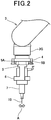
- Figure 2 is an enlarged diagram illustrating the arm distal end portion 3G of the processing device 1.
- An air-driven sliding table 4 is attached to the arm distal end portion 3G, and a sliding section 5 is movably provided on the sliding table 4.
- the sliding section 5 is driven by a pair of pneumatic cylinders 5A and 5A, which are actuated by air pressures applied to a pair of air supply ports (not illustrated) provided on opposite sides of the arm distal end portion 3G.
- Each of the pressures applied to the respective air supply ports provided on the opposite sides of the arm distal end portion 3G can independently be controlled so as to achieve a balance between the pressures. If a weight of a tool becomes a load because of a position of the tool, the pressures applied to the respective air supply ports are automatically adjusted according to the position of the tool so as to cancel the weight of the tool out.
- An ultrasonic transducer holder 6 is attached to the sliding section 5, which floats relative to a resin molding, and an ultrasonic transducer (transducer, vibrator or oscillator) 7 is attached to the ultrasonic transducer holder 6.
- the ultrasonic transducer 7 is not limited to a transducer using ultrasound.
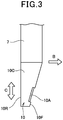
- Figure 3 is a plan view illustrating a cutter blade 10 and a part of attachment of the cutter blade 10
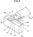
- Figure 4 is an enlarged perspective view illustrating the cutter blade 10 and the part of the attachment of the cutter blade 10 during deburring operation.
- the cutter blade 10 is fixed at a distal end of the ultrasonic transducer 7.
- the cutter blade 10 includes a front end surface 10F and a rear end surface 10R, and is brought into abutment with a base portion (root) of a burr 22 formed on a partition line 21 of a resin molding 20 of a composite material, for example, CFRP (or FRP or GFRP or the like), which is an object to be processed, and surface portions 23A and 23B of the resin molding 20 and cuts the burr 22 off.
- CFRP or FRP or GFRP or the like
- a setback angle ⁇ of the front end surface 10F which is arbitrarily set, is set to around 10°.
- the cutter blade 10 includes: a cutting edge portion 10A to be brought into abutment with the root of the burr 22 and cut the burr 22 off, the cutting edge portion 10A having a width W of, for example, around 10 mm; curved profiling portion 10B to be brought into abutment with and profile the respective surface portions 23A and 23B of the resin molding 20; and a flat plate-shaped cutter blade body 10C with the cutting edge portion 10A and the profiling portion 10B formed therein.
- the width W of the cutting edge portion 10A can arbitrarily be changed according to, e.g., the shape of the burr formed corresponding to the object to be processed.
- the cutter blade 10 can perform shaving processing of shaving a ridge, a projection or the like formed on a surface of a resin molding 20 like a chisel or the like to flatten the surface of the resin molding 20.
- the cutter blade 10 is biased against the resin molding 20, which is similar to the case described above.
- Figure 5 is a cross-sectional view illustrating a distal end part of the cutter blade 10.
- the cutting edge portion 10A of the cutter blade 10 includes a cutting edge 10g, which is a ridgeline formed by a rake surface 10e and a side surface 10f positioned on the resin molding 20 side of the cutter blade 10.
- a wedge angle ⁇ of the cutting edge portion 10A of the cutter blade 10 is set to 15° to 80°.
- the side surface 10f of the cutter blade 10 is in abutment with a surface of the resin molding 20, and a total of the wedge angle ⁇ and a positive rake angle ⁇ is 90°.
- the profiling portion 10B of the cutter blade 10 is a part to be pressed against the respective surface portions 23A and 23B (only the surface portion 23B illustrated) of the resin molding 20 by the floating mechanism, is positioned ahead of (in the vicinity of) the cutting edge 10g (blade edge) of the cutting edge portion 10A in an advancement direction (arrow B direction) and includes a rounded surface portion 10B1 that has a circular arc shape in cross section and extends forward from the cutting edge 10g of the cutting edge portion 10A in the advancement direction (arrow B direction).
- the wedge angle ⁇ of the cutting edge portion 10A exceeds 80°, the cutting edge portion 10A cuts poorly. Also, if the wedge angle ⁇ of the cutting edge portion 10A is less than 15°, damage such as chipping, breakage and/or abrasion of the cutting edge portion 10A is likely to occur.
- the cutting edge portion 10A can be restrained from digging into the material, enabling suppression of occurrence of a failure such as fracturing of the cutting edge portion 10A.
- the wedge angle ⁇ is set to 15° to 80°, the wedge angle ⁇ is desirably 30° to 80°, more desirably 40° to 60°, even more desirably 45° to 55°.
- the six-axis vertical articulated robot 3 of the processing device 1 controls operation of the joints 3A to 3F so that an orientation and a drive direction of the cutter blade 10 of the arm distal end portion 3G become optimum, for a resin molding 20, which is an object to be processed, along a deburring path corresponding to a position where a burr 22 is formed.
- the sliding section 5 of the arm distal end portion 3G floats relative to the resin molding 20.
- the pressures applied to the respective air supply ports are controlled.
- the sliding section 5 is driven by the pair of pneumatic cylinders 5A and 5A and the cutter blade 10 is pressed against the resin molding 20 at a predetermined pressure.
- the pressures applied to the respective air supply ports can automatically be changed according to the position of the cutter blade 10, and are consistently constant irrespective of the position of the cutter blade 10.
- the profiling portion 10B is pressed against surface portions 23A and 23B of the resin molding 20 and is moved to cut off a burr 22 formed on a partition line (corresponding to a deburring path) 21 of the resin molding 20 along a root of the burr 22 by means of the cutting edge portion 10A and smooth the surface after the cutting by means of the profiling portion 10B.
- the burr 22 of the resin molding 20 having an unstable shape can be removed at the root thereof without using an expensive control device, a workpiece positioning device or an expensive cutter blade and without the cutting edge portion 10A digging into the resin molding 20.
- the floating mechanism is provided and profiling control is performed, and thus, almost no work corresponding to a correction of a teaching position is required, enabling substantial processing time reduction.
- the blade edge of the cutting edge portion 10A is positioned behind the profiling portion 10B, and thus, even if there is a deformation in the resin molding 20, the cutting edge portion 10A can further be restrained from digging into the resin molding 20.
- the cutter blade body 10C has a flat plate shape, and thus, enables the cutter blade 10 to easily follow the resin molding 20, enabling enhancement in processability.
- the cutter blade 10 is used for shaving processing, enabling enhancement in accuracy of finish of a processed surface of a processed object (resin molding 20), which is of a difficult-to-cut material.
- Figure 6 is a cross-sectional view illustrating another mode of use of the cutter blade 10 according to the first example.
- a position where the profiling portion 10B abuts against a workpiece varies according to, e.g., a posture of the six-axis vertical articulated robot 3 and/or a shape of the workpiece.
- processing is performed with the side surface 10f of the cutter blade 10 away from a surface of a resin molding 20.
- a positive rake angle ⁇ ' is small compared to the mode in Figure 5 .
- the wedge angle ⁇ is set to 15° to 80°, damage such as chipping, breakage or abrasion of the cutting edge portion 10A is less likely to occur, the durability of the cutter blade 10 is enhanced and the cutter blade 10 cuts well.
- Figure 7 is a cross-sectional view illustrating a distal end part of a cutter blade 30 according to a second example not according to the present invention.
- the cutter blade 30 includes a cutting edge portion 30A to be brought into abutment with and cut off a root of a burr 22, and profiling portion 10B to be pressed against surface portions 23A and 23B (only the surface portion 23B illustrated) of a resin molding 20 by a floating mechanism.
- the cutting edge portion 30A includes a cutting edge 30g corresponding to a ridgeline formed by a rake surface 30e and a side surface 30f positioned on the resin molding 20 side of the cutter blade 30.
- a wedge angle ⁇ of the cutting edge portion 30A is set to 93° to 120°.
- the side surface 30f of the cutter blade 30 is in abutment with a surface of the resin molding 20, and an angle resulting from a negative rake angle ⁇ being subtracted from the wedge angle ⁇ is 90°.
- the profiling portion 10B is positioned ahead of the cutting edge 30g (blade edge) of the cutting edge portion 30A in an advancement direction (arrow B direction), and includes a rounded surface portion 10B1 having a circular arc shape in cross section and extending ahead from the cutting edge 30g of the cutting edge portion 30A in the advancement direction (arrow B direction).
- the cutter blade 30 can perform shaving processing of shaving a ridge, a projection or the like formed on a surface of a resin molding 20 like a chisel or the like to flatten the surface of the resin molding 20.
- the cutter blade 30 is biased against the resin molding 20, which is similar to the cases described above.
- the wedge angle ⁇ of the cutting edge portion 30A is 90° ⁇ ⁇ ⁇ 93°, a cut amount is large, which causes chatter vibration, resulting in deterioration in finish of the processed surface. If the wedge angle ⁇ exceeds 120°, the cut amount is smaller, resulting in failure to sufficiently remove the burr.
- the negative rake angle of the cutting edge portion 30A enables smoothing the surface after the removal of the burr 22, enabling the processed surface to be smoother. Also, chatter vibration is less likely to occur, ensuring a sufficient cut amount.
- the wedge angle ⁇ is set to 93° to 120°, the wedge angle ⁇ may be 95° to 120°, and is desirably 95° to 115°, more desirably 95° to 100°.
- the cutter blades 10 and 30 in Figures 5 and 6 even if the cutter blades 10 and 30 are formed so as to have a wedge angle ⁇ of 80° ⁇ ⁇ ⁇ 93°, the cutter blades 10 and 30 can be used for deburring processing, depending on, e.g., a material, a hardness and/or a shape of an object to be processed and/or the type of the cutter blade.
- a processing device 1 in which pneumatic cylinders 5A and 5A are provided in a six-axis vertical articulated robot 3 and a cutter blade 10 or 30 is provided in the six-axis vertical articulated robot 3 via the pneumatic cylinders 5A and 5A includes a cutter blade 30 that includes profiling portion 10B corresponding to a resin molding 20 and that further includes a cutting edge portion 30A including a blade edge positioned in the vicinity of the profiling portion 10B and having a wedge angle ⁇ of 15° to 120°, the profiling portion 10B and the cutting edge portion 30A being integrated, and thus, the wedge angle ⁇ of the cutting edge portion 10A or 30A included in the processing device 1 is made to be large compared to those of the conventional techniques, enabling processing of a composite material, for example, FRP, CFRP or GFRP, which is a difficult-to-cut material without damage such as chipping of the cutting edge portion 30A.
- a composite material for example, FRP, CFRP or GFRP
- the provision of the profiling portion 10B enables the cutting edge portion 10A or 30A to be restrained from digging into a resin molding 20.
- the blade edge of the cutting edge portion 30A is positioned behind the profiling portion 10B, and thus, even if there is a deformation in the resin molding 20, the cutting edge portion 30A can further be restrained from digging into the resin molding 20.
- the cutter blade 30 shaves the resin molding 20, enabling enhancement in accuracy of finish of the processed surface of the processed object (resin molding 20), which is of a difficult-to-cut material.
- Figure 8 is a cross-sectional view illustrating a distal end part of a cutter blade 35 according to a third example not according to the present invention.
- the cutter blade 35 includes a cutting edge portion 35A to be brought into abutment with and cut off a root of a burr 22, and a profiling surface 35f, which serves as a profiling portion to be pressed against surface portions 23A and 23B (only the surface portion 23B illustrated) of a resin molding 20 by a floating mechanism.
- the cutting edge portion 35A includes a cutting edge 35g corresponding to a ridgeline formed by a rake surface 35e and the profiling surface 35f.
- a wedge angle ⁇ of the cutting edge portion 35A is set to 15° to 80°.
- the profiling surface 35f includes the cutting edge 35g, and the profiling surface 35f extends rearward from the cutting edge 35g (blade edge) in an advancement direction (arrow B direction).
- the cutter blade 35 can perform shaving processing of shaving a ridge, a projection or the like formed on a surface of a resin molding 20 like a chisel or the like to flatten the surface of the resin molding 20.
- the cutter blade 35 is biased against the resin molding 20, which is similar to the cases described above.
- the cutting edge 35g (blade edge) is positioned at a distal end portion of the profiling surface 35f, allowing the profiling surface 35f, which forms a part of the cutting edge 35g, to serves as a profiling portion, and thus, the cutter blade 35 can be formed in a simple shape, enabling cost reduction.
- the wedge angle ⁇ is set to 15° to 80°, the wedge angle ⁇ is desirably 30° to 80°, more desirably 40° to 60°, even more desirably 45° to 55°.
- Figure 9 is a cross-sectional view illustrating a distal end part of a cutter blade 40 according to a fourth example not according to the present invention.
- the cutter blade 40 includes a cutting edge portion 40A to be brought into abutment with and cut off a root of a burr 22, and a profiling surface 40f, which serves as a profiling portion to be pressed against surface portions 23A and 23B (only the surface portion 23B illustrated) of a resin molding 20 by a floating mechanism.
- the cutting edge portion 40A includes a cutting edge 40g corresponding to a ridgeline formed by a rake surface 40e and the profiling surface 40f.
- a wedge angle ⁇ of the cutting edge portion 40A is set to 93° to 120°.
- the profiling surface 40f includes the cutting edge 40g, and the profiling surface 40f extends rearward from the cutting edge 40g (blade edge) in an advancement direction (arrow B direction).
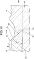
- Figure 10 is a cross-sectional view illustrating a distal end part of a cutter blade 42 according to a fifth example, which is an embodiment of the present invention.
- Components that are identical to those of the first example illustrated in Figure 5 and the third example illustrated in Figure 8 are provided with reference numerals that are the same as those of the first and third examples, and detailed description thereof will be omitted.
- the cutter blade 42 includes a cutting edge portion 42A to be brought into abutment with and cut off a root of a burr 22, and a profiling surface 42f, which serves as a profiling portion to be pressed against surface portions 23A and 23B (only the surface portion 23B illustrated) of a resin molding 20 by a floating mechanism.
- the cutting edge portion 42A includes a cutting edge 42g corresponding to a ridgeline formed by a rake surface 42e and the profiling surface 42f.
- a wedge angle ⁇ of the rake surface 42e is set to 15° to 80°.
- the profiling surface 42f includes the cutting edge 42g, and the profiling surface 42f extends rearward from the cutting edge 42g (blade edge) in an advancement direction (arrow B direction). Behind the profiling surface 42f, the cutter blade 42 includes a clearance portion 42j away from the surface portions 23A and 23B.
- the wedge angle ⁇ of the cutting edge portion 42A exceeds 80°, the cutting edge portion 42A cuts poorly. Also, if the wedge angle ⁇ of the cutting edge portion 42A is less than 15°, damage such as chipping, breakage and/or abrasion of the cutting edge portion 42A is likely to occur.
- the wedge angle ⁇ is set to 30° to 80°, more desirably 40° to 60°, even more desirably 45° to 55°.
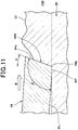
- Figure 11 is a cross-sectional view illustrating a distal end part of a cutter blade 44 according to a sixth example, which is an embodiment of the present invention.
- the cutter blade 44 includes a cutting edge portion 44A to be brought into abutment with and cut off a root of a burr 22, and a profiling surface 44f, which serves as a profiling portion to be pressed against surface portions 23A and 23B (only the surface portion 23B illustrated) of a resin molding 20 by a floating mechanism.
- the cutting edge portion 44A includes a cutting edge 44g corresponding to a ridgeline formed by a rake surface 44e and the profiling surface 44f.
- a wedge angle ⁇ of the cutting edge portion 44A is set to 93° to 120°.
- the profiling surface 44f includes the cutting edge 44g, and the profiling surface 44f extends rearward from the cutting edge 44g (blade edge) in an advancement direction (arrow B direction). Behind the profiling surface 44f, the cutter blade 44 includes a clearance portion 44j away from the surface portions 23A and 23B.
- the wedge angle ⁇ of cutting edge portion 44A is 90 ⁇ ⁇ ⁇ 93°, a cut amount is large, which causes chatter vibration, resulting in deterioration in finish of the processed surface. If the wedge angle ⁇ exceeds 120°, the cut amount is small, resulting in failure to sufficiently remove the burr.
- the cutter blade can be used for deburring processing, depending on, e.g., a material, a hardness and/or a shape of an object to be processed and/or the type of the cutter blade.
- the biasing mechanism is provided by the pneumatic cylinders 5A, but the biasing mechanism is not limited to that provided by the pneumatic cylinders 5A, and may be provided by other means such as a spring or a solenoid.
- the processing device 1 includes the six-axis vertical articulated robot 3; however, the present invention is not limited to this case, and the processing device 1 may include another type of robot.
- the above-described cutter blade 10 can be ultrasonically vibrated in a direction (arrow C direction (see Figure 3 )) substantially perpendicular to the advancement direction (arrow B direction (see Figure 3 )) of the cutter blade 10, according to vibration of the ultrasonic transducer 7.
- An ultrasonic unit (not illustrated) is connected to the ultrasonic transducer 7, enabling the cutter blade 10 to be driven with an amplitude of, for example, around 30 to 50 ⁇ m by the ultrasonic unit.
- deburring processing may be performed with the cutter blade 10 ultrasonically vibrated, depending on, e.g., a material, a hardness or a shape of an object to be processed.
Landscapes
- Engineering & Computer Science (AREA)
- Mechanical Engineering (AREA)
- Life Sciences & Earth Sciences (AREA)
- Forests & Forestry (AREA)
- Processing And Handling Of Plastics And Other Materials For Molding In General (AREA)
- Control Of Cutting Processes (AREA)
- Nonmetal Cutting Devices (AREA)
- Milling Processes (AREA)
Claims (5)
- Schneideklinge (42) zur Befestigung an einem Roboter mittels eines Vorspannmechanismus, wobei die Schneideklinge (42) umfasst:eine Profilierungsoberfläche (42f) zum Drücken gegen einen Oberflächenteil (23B) eines Werkstücks (20) mittels des Vorspannmechanismus undeinen Schneideklingenteil (42A), der eine Schneide (42g) einschließt, die auf einer Kammlinie angeordnet ist, die durch die Profilierungsoberfläche (42f) undeine Schrägoberfläche (42e) gebildet ist, wobei der Schneideklingenteil (42A) einen Abstandsteil (42j) einschließt, der, relativ zu einer Fortschrittsrichtung (B), hinter der Profilierungsoberfläche (42f) angeordnet ist, zur Vibration in Benutzung durch einen Wandler und gekennzeichnet durch das Aufweisen eines Keilwinkels (β) von 30° bis 80°, wobei die Profilierungsoberfläche (42f) und der Schneidklingenteil (42A) integriert sind.
- Schneideklinge (44) zur Befestigung an einem Roboter mittels eines Vorspannmechanismus, wobei die Schneideklinge (44) umfasst:eine Profilierungsoberfläche (44f) zum Drücken gegen einen Oberflächenteil (23B) eines Werkstücks (20) mittels des Vorspannmechanismus undeinen Schneideklingenteil (44A), der eine Schneide (44g) einschließt, die auf einer Kammlinie angeordnet ist, die durch die Profilierungsoberfläche (44f) undeine Schrägoberfläche (44e) gebildet ist, wobei der Schneideklingenteil (44A) einen Abstandsteil (44j) einschließt, der, relativ zu einer Fortschrittsrichtung (B), hinter der Profilierungsoberfläche (44f) angeordnet ist und dadurchgekennzeichnet ist, dass er einen Keilwinkel (β) von 93° bis 120° aufweist, wobei die Profilierungsoberfläche (44f) und der Schneidklingenteil (44A) integriert sind.
- Schneideklinge (42, 44) gemäß Anspruch 1 oder 2, wobei ein Schneideklingenkörper eine flache Plattenform aufweist.
- Bearbeitungsvorrichtung, die eine Schneideklinge (42) gemäß Anspruch 1 einschließt, die in einem Roboter mittels eines Vorspannmechanismus bereitgestellt ist.
- Bearbeitungsvorrichtung, die eine Schneideklinge (44) gemäß Anspruch 2 einschließt, die in einem Roboter mittels eines Vorspannmechanismus bereitgestellt ist.
Applications Claiming Priority (1)
| Application Number | Priority Date | Filing Date | Title |
|---|---|---|---|
| PCT/JP2013/077859 WO2015052846A1 (ja) | 2013-10-11 | 2013-10-11 | カッター刃、加工装置 |
Publications (3)
| Publication Number | Publication Date |
|---|---|
| EP3056324A1 EP3056324A1 (de) | 2016-08-17 |
| EP3056324A4 EP3056324A4 (de) | 2017-06-21 |
| EP3056324B1 true EP3056324B1 (de) | 2018-09-19 |
Family
ID=51579118
Family Applications (1)
| Application Number | Title | Priority Date | Filing Date |
|---|---|---|---|
| EP13895189.2A Active EP3056324B1 (de) | 2013-10-11 | 2013-10-11 | Schneidemesser und verarbeitungsvorrichtung |
Country Status (6)
| Country | Link |
|---|---|
| US (1) | US20160236287A1 (de) |
| EP (1) | EP3056324B1 (de) |
| JP (1) | JP5579332B6 (de) |
| CN (1) | CN105592988A (de) |
| ES (1) | ES2702154T3 (de) |
| WO (1) | WO2015052846A1 (de) |
Families Citing this family (11)
| Publication number | Priority date | Publication date | Assignee | Title |
|---|---|---|---|---|
| DE102013009251A1 (de) * | 2013-06-03 | 2014-12-04 | Günter Bröker | Vorrichtung zur schneidenden Bearbeitung von Material und Schneideinheit mit oszillierendem Schneidmesser und veränderlichem Schnittneigungswinkel |
| JP2017196667A (ja) * | 2014-08-01 | 2017-11-02 | 帝人株式会社 | 超音波ナイフ、及びこれを用いて切断成形体を製造する方法 |
| CN106409725B (zh) * | 2016-10-08 | 2019-04-09 | 北京无线电测量研究所 | 一种用于芯片切割实验的工装及方法 |
| US20180166294A1 (en) * | 2016-12-13 | 2018-06-14 | Intel Corporation | Apparatus and methods to achieve uniform package thickness |
| CN109176727B (zh) * | 2018-09-12 | 2024-03-19 | 海目星激光科技集团股份有限公司 | 一种用于热切割的加工装置 |
| DK4008500T3 (da) | 2020-10-19 | 2023-03-13 | Nihon Shoryoku Kikai Co Ltd | Bearbejdningsindretning |
| WO2022107201A1 (ja) * | 2020-11-17 | 2022-05-27 | スターテクノ株式会社 | ワーク加工装置及びそのワーク加工装置を備えた超音波加工装置 |
| TWI835645B (zh) * | 2022-05-11 | 2024-03-11 | 日商前川製作所股份有限公司 | 切削裝置以及工件的切削方法 |
| USD1099998S1 (en) * | 2022-06-22 | 2025-10-28 | Inland Diamond Products Company | Cutter blade for an ophthalmic lens edger |
| NL2037079B1 (en) * | 2024-02-21 | 2025-08-28 | R Van Den Hanenberg B V | Method of forming an elastomeric element. |
| CN118927309B (zh) * | 2024-10-14 | 2025-02-14 | 四川帕沃可矿物纤维制品集团有限公司 | 一种高强度玄武岩挡雪板的生产切割装置 |
Family Cites Families (18)
| Publication number | Priority date | Publication date | Assignee | Title |
|---|---|---|---|---|
| CH221326A (fr) * | 1941-08-05 | 1942-05-31 | Max Blanchod S A | Couteau pour rogneuse automatique. |
| US2936679A (en) * | 1956-07-02 | 1960-05-17 | Giddings & Lewis | Method for cutting metal |
| DE2743258A1 (de) * | 1977-09-26 | 1979-03-29 | Aiguisage Service S A | Klinge fuer papierschneidemaschinen und verfahren zu deren schleifen |
| JPS5970665U (ja) * | 1982-11-01 | 1984-05-14 | 赤司 乗二 | プラスチツク品等のバリ取り刃具 |
| EP0470730B1 (de) * | 1990-08-08 | 1996-04-17 | Oki Electric Industry Co., Ltd. | Ultraschallschleifsystem für keramisches Filter und Verfahren zum Abgleich dafür |
| CN2293410Y (zh) * | 1997-02-14 | 1998-10-07 | 张滨 | 抗崩刃硬质合金刨刀片 |
| CN1223183A (zh) * | 1997-10-21 | 1999-07-21 | 住友电气工业株式会社 | 一种高精确度切削淬火钢的方法 |
| CN2342924Y (zh) * | 1998-08-21 | 1999-10-13 | 戴礼贤 | 加工针刺状金属管、棒的护根铲刀 |
| JP3721507B2 (ja) * | 1998-11-24 | 2005-11-30 | Jfeスチール株式会社 | バリ取り方法およびその装置 |
| US6755105B2 (en) * | 2001-06-01 | 2004-06-29 | The Goodyear Tire & Rubber Company | Method and apparatus for cutting elastomeric materials and the article made by the method |
| US20030021861A1 (en) * | 2001-06-20 | 2003-01-30 | Nihon Plast Co., Ltd. | Deflashing apparatus |
| JP2003001639A (ja) * | 2001-06-20 | 2003-01-08 | Nippon Plast Co Ltd | 成形品のバリ除去装置 |
| JP4087608B2 (ja) * | 2002-01-25 | 2008-05-21 | オークマ株式会社 | 切削工具、および該切削工具を用いた切削加工方法 |
| US8057498B2 (en) * | 2007-11-30 | 2011-11-15 | Ethicon Endo-Surgery, Inc. | Ultrasonic surgical instrument blades |
| ES2833225T3 (es) * | 2007-12-27 | 2021-06-14 | Nihon Shoryoku Kikai Co Ltd | Sistema de desbarbado, aparato de desbarbado y cuchilla de cortador |
| JP4231895B2 (ja) | 2008-06-23 | 2009-03-04 | 日本省力機械株式会社 | バリ取り装置 |
| WO2012020446A1 (ja) * | 2010-08-09 | 2012-02-16 | 日本省力機械株式会社 | スクレイパー式バリ取り装置 |
| JP4955823B1 (ja) * | 2011-04-05 | 2012-06-20 | 日本省力機械株式会社 | ワーク取り出し仕上げ装置 |
-
2013
- 2013-10-11 US US15/025,125 patent/US20160236287A1/en not_active Abandoned
- 2013-10-11 EP EP13895189.2A patent/EP3056324B1/de active Active
- 2013-10-11 ES ES13895189T patent/ES2702154T3/es active Active
- 2013-10-11 JP JP2013548684A patent/JP5579332B6/ja active Active
- 2013-10-11 CN CN201380079887.1A patent/CN105592988A/zh active Pending
- 2013-10-11 WO PCT/JP2013/077859 patent/WO2015052846A1/ja not_active Ceased
Non-Patent Citations (1)
| Title |
|---|
| None * |
Also Published As
| Publication number | Publication date |
|---|---|
| ES2702154T3 (es) | 2019-02-27 |
| JPWO2015052846A1 (ja) | 2017-03-09 |
| JP5579332B6 (ja) | 2018-06-27 |
| CN105592988A (zh) | 2016-05-18 |
| WO2015052846A1 (ja) | 2015-04-16 |
| JP5579332B1 (ja) | 2014-08-27 |
| EP3056324A4 (de) | 2017-06-21 |
| EP3056324A1 (de) | 2016-08-17 |
| US20160236287A1 (en) | 2016-08-18 |
Similar Documents
| Publication | Publication Date | Title |
|---|---|---|
| EP3056324B1 (de) | Schneidemesser und verarbeitungsvorrichtung | |
| JPWO2015052846A6 (ja) | カッター刃、加工装置 | |
| WO2009084093A1 (ja) | バリ取りシステム、バリ取り装置およびカッター刃 | |
| US20240017338A1 (en) | Saw blade | |
| US9027452B2 (en) | Jab saw accessory tool for an oscillating tool | |
| JP5766493B2 (ja) | アブレイシブウォータージェット加工装置 | |
| JP4231895B2 (ja) | バリ取り装置 | |
| US10478908B2 (en) | Oscillating jig saw blade | |
| WO2010131308A1 (ja) | 樹脂製品製造システム、製造方法、樹脂成形装置、及び金型 | |
| KR20120054591A (ko) | 스트링어의 제조방법 | |
| JP4169769B2 (ja) | バリ取り装置およびカッター刃 | |
| JP4685976B1 (ja) | スクレイパー式バリ取り装置 | |
| JP4586105B2 (ja) | 樹脂製品製造システム、製造方法、樹脂成形装置、及び金型 | |
| JP7222541B2 (ja) | 電動式スクレーパーの替刃 | |
| WO2006104523A3 (en) | Waste ejecting blade assemblies for hand-held cutting tools | |
| CN101142046B (zh) | 用于具有倒行工作危险的加工作业的工具和机床 | |
| TWI530379B (zh) | 毛邊移除裝置 | |
| JP4802745B2 (ja) | 切削インサート及びインサート着脱式切削工具 | |
| CN215880760U (zh) | 一种带断屑槽的pcd铣刀夹 | |
| CN115533973B (zh) | 一种复合材料薄板的加工方法及复合材料薄板 | |
| WO2024071324A1 (ja) | キサゲ加工装置、及びキサゲ加工方法 | |
| CN204657497U (zh) | 可拆式焊接车刀 | |
| Benes | Get an edge on tool performance | |
| JP2004058634A (ja) | 替刃式鑿及び替刃 | |
| HK1186702B (en) | Cutter blade and deburring system |
Legal Events
| Date | Code | Title | Description |
|---|---|---|---|
| PUAI | Public reference made under article 153(3) epc to a published international application that has entered the european phase |
Free format text: ORIGINAL CODE: 0009012 |
|
| 17P | Request for examination filed |
Effective date: 20160510 |
|
| AK | Designated contracting states |
Kind code of ref document: A1 Designated state(s): AL AT BE BG CH CY CZ DE DK EE ES FI FR GB GR HR HU IE IS IT LI LT LU LV MC MK MT NL NO PL PT RO RS SE SI SK SM TR |
|
| AX | Request for extension of the european patent |
Extension state: BA ME |
|
| DAX | Request for extension of the european patent (deleted) | ||
| A4 | Supplementary search report drawn up and despatched |
Effective date: 20170518 |
|
| RIC1 | Information provided on ipc code assigned before grant |
Ipc: B26D 1/10 20060101AFI20170512BHEP Ipc: B26D 5/08 20060101ALI20170512BHEP Ipc: B26D 3/00 20060101ALI20170512BHEP Ipc: B26D 1/00 20060101ALN20170512BHEP |
|
| STAA | Information on the status of an ep patent application or granted ep patent |
Free format text: STATUS: EXAMINATION IS IN PROGRESS |
|
| 17Q | First examination report despatched |
Effective date: 20171211 |
|
| GRAP | Despatch of communication of intention to grant a patent |
Free format text: ORIGINAL CODE: EPIDOSNIGR1 |
|
| STAA | Information on the status of an ep patent application or granted ep patent |
Free format text: STATUS: GRANT OF PATENT IS INTENDED |
|
| RIC1 | Information provided on ipc code assigned before grant |
Ipc: B26D 1/10 20060101AFI20180425BHEP Ipc: B26D 5/08 20060101ALI20180425BHEP Ipc: B26D 3/00 20060101ALI20180425BHEP Ipc: B26D 1/00 20060101ALN20180425BHEP |
|
| INTG | Intention to grant announced |
Effective date: 20180511 |
|
| GRAS | Grant fee paid |
Free format text: ORIGINAL CODE: EPIDOSNIGR3 |
|
| GRAA | (expected) grant |
Free format text: ORIGINAL CODE: 0009210 |
|
| STAA | Information on the status of an ep patent application or granted ep patent |
Free format text: STATUS: THE PATENT HAS BEEN GRANTED |
|
| AK | Designated contracting states |
Kind code of ref document: B1 Designated state(s): AL AT BE BG CH CY CZ DE DK EE ES FI FR GB GR HR HU IE IS IT LI LT LU LV MC MK MT NL NO PL PT RO RS SE SI SK SM TR |
|
| REG | Reference to a national code |
Ref country code: GB Ref legal event code: FG4D |
|
| REG | Reference to a national code |
Ref country code: CH Ref legal event code: EP |
|
| REG | Reference to a national code |
Ref country code: DE Ref legal event code: R096 Ref document number: 602013044084 Country of ref document: DE |
|
| REG | Reference to a national code |
Ref country code: AT Ref legal event code: REF Ref document number: 1042715 Country of ref document: AT Kind code of ref document: T Effective date: 20181015 |
|
| REG | Reference to a national code |
Ref country code: IE Ref legal event code: FG4D |
|
| REG | Reference to a national code |
Ref country code: FR Ref legal event code: PLFP Year of fee payment: 6 |
|
| REG | Reference to a national code |
Ref country code: CH Ref legal event code: NV Representative=s name: TROESCH SCHEIDEGGER WERNER AG, CH |
|
| REG | Reference to a national code |
Ref country code: NL Ref legal event code: MP Effective date: 20180919 |
|
| PG25 | Lapsed in a contracting state [announced via postgrant information from national office to epo] |
Ref country code: BG Free format text: LAPSE BECAUSE OF FAILURE TO SUBMIT A TRANSLATION OF THE DESCRIPTION OR TO PAY THE FEE WITHIN THE PRESCRIBED TIME-LIMIT Effective date: 20181219 Ref country code: SE Free format text: LAPSE BECAUSE OF FAILURE TO SUBMIT A TRANSLATION OF THE DESCRIPTION OR TO PAY THE FEE WITHIN THE PRESCRIBED TIME-LIMIT Effective date: 20180919 Ref country code: NO Free format text: LAPSE BECAUSE OF FAILURE TO SUBMIT A TRANSLATION OF THE DESCRIPTION OR TO PAY THE FEE WITHIN THE PRESCRIBED TIME-LIMIT Effective date: 20181219 Ref country code: LT Free format text: LAPSE BECAUSE OF FAILURE TO SUBMIT A TRANSLATION OF THE DESCRIPTION OR TO PAY THE FEE WITHIN THE PRESCRIBED TIME-LIMIT Effective date: 20180919 Ref country code: GR Free format text: LAPSE BECAUSE OF FAILURE TO SUBMIT A TRANSLATION OF THE DESCRIPTION OR TO PAY THE FEE WITHIN THE PRESCRIBED TIME-LIMIT Effective date: 20181220 Ref country code: FI Free format text: LAPSE BECAUSE OF FAILURE TO SUBMIT A TRANSLATION OF THE DESCRIPTION OR TO PAY THE FEE WITHIN THE PRESCRIBED TIME-LIMIT Effective date: 20180919 Ref country code: RS Free format text: LAPSE BECAUSE OF FAILURE TO SUBMIT A TRANSLATION OF THE DESCRIPTION OR TO PAY THE FEE WITHIN THE PRESCRIBED TIME-LIMIT Effective date: 20180919 |
|
| REG | Reference to a national code |
Ref country code: LT Ref legal event code: MG4D |
|
| REG | Reference to a national code |
Ref country code: ES Ref legal event code: FG2A Ref document number: 2702154 Country of ref document: ES Kind code of ref document: T3 Effective date: 20190227 |
|
| PG25 | Lapsed in a contracting state [announced via postgrant information from national office to epo] |
Ref country code: HR Free format text: LAPSE BECAUSE OF FAILURE TO SUBMIT A TRANSLATION OF THE DESCRIPTION OR TO PAY THE FEE WITHIN THE PRESCRIBED TIME-LIMIT Effective date: 20180919 Ref country code: AL Free format text: LAPSE BECAUSE OF FAILURE TO SUBMIT A TRANSLATION OF THE DESCRIPTION OR TO PAY THE FEE WITHIN THE PRESCRIBED TIME-LIMIT Effective date: 20180919 Ref country code: LV Free format text: LAPSE BECAUSE OF FAILURE TO SUBMIT A TRANSLATION OF THE DESCRIPTION OR TO PAY THE FEE WITHIN THE PRESCRIBED TIME-LIMIT Effective date: 20180919 |
|
| REG | Reference to a national code |
Ref country code: AT Ref legal event code: MK05 Ref document number: 1042715 Country of ref document: AT Kind code of ref document: T Effective date: 20180919 |
|
| PG25 | Lapsed in a contracting state [announced via postgrant information from national office to epo] |
Ref country code: RO Free format text: LAPSE BECAUSE OF FAILURE TO SUBMIT A TRANSLATION OF THE DESCRIPTION OR TO PAY THE FEE WITHIN THE PRESCRIBED TIME-LIMIT Effective date: 20180919 Ref country code: EE Free format text: LAPSE BECAUSE OF FAILURE TO SUBMIT A TRANSLATION OF THE DESCRIPTION OR TO PAY THE FEE WITHIN THE PRESCRIBED TIME-LIMIT Effective date: 20180919 Ref country code: AT Free format text: LAPSE BECAUSE OF FAILURE TO SUBMIT A TRANSLATION OF THE DESCRIPTION OR TO PAY THE FEE WITHIN THE PRESCRIBED TIME-LIMIT Effective date: 20180919 Ref country code: IS Free format text: LAPSE BECAUSE OF FAILURE TO SUBMIT A TRANSLATION OF THE DESCRIPTION OR TO PAY THE FEE WITHIN THE PRESCRIBED TIME-LIMIT Effective date: 20190119 Ref country code: NL Free format text: LAPSE BECAUSE OF FAILURE TO SUBMIT A TRANSLATION OF THE DESCRIPTION OR TO PAY THE FEE WITHIN THE PRESCRIBED TIME-LIMIT Effective date: 20180919 Ref country code: PL Free format text: LAPSE BECAUSE OF FAILURE TO SUBMIT A TRANSLATION OF THE DESCRIPTION OR TO PAY THE FEE WITHIN THE PRESCRIBED TIME-LIMIT Effective date: 20180919 Ref country code: CZ Free format text: LAPSE BECAUSE OF FAILURE TO SUBMIT A TRANSLATION OF THE DESCRIPTION OR TO PAY THE FEE WITHIN THE PRESCRIBED TIME-LIMIT Effective date: 20180919 |
|
| PG25 | Lapsed in a contracting state [announced via postgrant information from national office to epo] |
Ref country code: SK Free format text: LAPSE BECAUSE OF FAILURE TO SUBMIT A TRANSLATION OF THE DESCRIPTION OR TO PAY THE FEE WITHIN THE PRESCRIBED TIME-LIMIT Effective date: 20180919 Ref country code: PT Free format text: LAPSE BECAUSE OF FAILURE TO SUBMIT A TRANSLATION OF THE DESCRIPTION OR TO PAY THE FEE WITHIN THE PRESCRIBED TIME-LIMIT Effective date: 20190119 Ref country code: SM Free format text: LAPSE BECAUSE OF FAILURE TO SUBMIT A TRANSLATION OF THE DESCRIPTION OR TO PAY THE FEE WITHIN THE PRESCRIBED TIME-LIMIT Effective date: 20180919 |
|
| REG | Reference to a national code |
Ref country code: DE Ref legal event code: R097 Ref document number: 602013044084 Country of ref document: DE |
|
| REG | Reference to a national code |
Ref country code: BE Ref legal event code: MM Effective date: 20181031 |
|
| PG25 | Lapsed in a contracting state [announced via postgrant information from national office to epo] |
Ref country code: LU Free format text: LAPSE BECAUSE OF NON-PAYMENT OF DUE FEES Effective date: 20181011 |
|
| REG | Reference to a national code |
Ref country code: IE Ref legal event code: MM4A |
|
| PLBE | No opposition filed within time limit |
Free format text: ORIGINAL CODE: 0009261 |
|
| STAA | Information on the status of an ep patent application or granted ep patent |
Free format text: STATUS: NO OPPOSITION FILED WITHIN TIME LIMIT |
|
| PG25 | Lapsed in a contracting state [announced via postgrant information from national office to epo] |
Ref country code: MC Free format text: LAPSE BECAUSE OF FAILURE TO SUBMIT A TRANSLATION OF THE DESCRIPTION OR TO PAY THE FEE WITHIN THE PRESCRIBED TIME-LIMIT Effective date: 20180919 Ref country code: DK Free format text: LAPSE BECAUSE OF FAILURE TO SUBMIT A TRANSLATION OF THE DESCRIPTION OR TO PAY THE FEE WITHIN THE PRESCRIBED TIME-LIMIT Effective date: 20180919 |
|
| 26N | No opposition filed |
Effective date: 20190620 |
|
| PG25 | Lapsed in a contracting state [announced via postgrant information from national office to epo] |
Ref country code: BE Free format text: LAPSE BECAUSE OF NON-PAYMENT OF DUE FEES Effective date: 20181031 |
|
| PG25 | Lapsed in a contracting state [announced via postgrant information from national office to epo] |
Ref country code: IE Free format text: LAPSE BECAUSE OF NON-PAYMENT OF DUE FEES Effective date: 20181011 Ref country code: SI Free format text: LAPSE BECAUSE OF FAILURE TO SUBMIT A TRANSLATION OF THE DESCRIPTION OR TO PAY THE FEE WITHIN THE PRESCRIBED TIME-LIMIT Effective date: 20180919 |
|
| PG25 | Lapsed in a contracting state [announced via postgrant information from national office to epo] |
Ref country code: MT Free format text: LAPSE BECAUSE OF NON-PAYMENT OF DUE FEES Effective date: 20181011 |
|
| PG25 | Lapsed in a contracting state [announced via postgrant information from national office to epo] |
Ref country code: TR Free format text: LAPSE BECAUSE OF FAILURE TO SUBMIT A TRANSLATION OF THE DESCRIPTION OR TO PAY THE FEE WITHIN THE PRESCRIBED TIME-LIMIT Effective date: 20180919 |
|
| PG25 | Lapsed in a contracting state [announced via postgrant information from national office to epo] |
Ref country code: HU Free format text: LAPSE BECAUSE OF FAILURE TO SUBMIT A TRANSLATION OF THE DESCRIPTION OR TO PAY THE FEE WITHIN THE PRESCRIBED TIME-LIMIT; INVALID AB INITIO Effective date: 20131011 Ref country code: MK Free format text: LAPSE BECAUSE OF NON-PAYMENT OF DUE FEES Effective date: 20180919 Ref country code: CY Free format text: LAPSE BECAUSE OF FAILURE TO SUBMIT A TRANSLATION OF THE DESCRIPTION OR TO PAY THE FEE WITHIN THE PRESCRIBED TIME-LIMIT Effective date: 20180919 |
|
| PGFP | Annual fee paid to national office [announced via postgrant information from national office to epo] |
Ref country code: ES Payment date: 20231117 Year of fee payment: 11 |
|
| PGFP | Annual fee paid to national office [announced via postgrant information from national office to epo] |
Ref country code: IT Payment date: 20231031 Year of fee payment: 11 Ref country code: CH Payment date: 20231102 Year of fee payment: 11 |
|
| PGFP | Annual fee paid to national office [announced via postgrant information from national office to epo] |
Ref country code: DE Payment date: 20241024 Year of fee payment: 12 |
|
| PGFP | Annual fee paid to national office [announced via postgrant information from national office to epo] |
Ref country code: GB Payment date: 20241121 Year of fee payment: 12 |
|
| PGFP | Annual fee paid to national office [announced via postgrant information from national office to epo] |
Ref country code: FR Payment date: 20241025 Year of fee payment: 12 |
|
| REG | Reference to a national code |
Ref country code: CH Ref legal event code: PL |
|
| PG25 | Lapsed in a contracting state [announced via postgrant information from national office to epo] |
Ref country code: CH Free format text: LAPSE BECAUSE OF NON-PAYMENT OF DUE FEES Effective date: 20241031 |
|
| PG25 | Lapsed in a contracting state [announced via postgrant information from national office to epo] |
Ref country code: IT Free format text: LAPSE BECAUSE OF NON-PAYMENT OF DUE FEES Effective date: 20241011 |
|
| REG | Reference to a national code |
Ref country code: ES Ref legal event code: FD2A Effective date: 20251128 |
|
| PG25 | Lapsed in a contracting state [announced via postgrant information from national office to epo] |
Ref country code: ES Free format text: LAPSE BECAUSE OF NON-PAYMENT OF DUE FEES Effective date: 20241012 |