EP3068678B1 - Träger mit u-förmigem profil - Google Patents
Träger mit u-förmigem profil Download PDFInfo
- Publication number
- EP3068678B1 EP3068678B1 EP14799145.9A EP14799145A EP3068678B1 EP 3068678 B1 EP3068678 B1 EP 3068678B1 EP 14799145 A EP14799145 A EP 14799145A EP 3068678 B1 EP3068678 B1 EP 3068678B1
- Authority
- EP
- European Patent Office
- Prior art keywords
- transition zone
- section
- side wall
- pillar
- beam according
- Prior art date
- Legal status (The legal status is an assumption and is not a legal conclusion. Google has not performed a legal analysis and makes no representation as to the accuracy of the status listed.)
- Active
Links
Images




Classifications
-
- B—PERFORMING OPERATIONS; TRANSPORTING
- B62—LAND VEHICLES FOR TRAVELLING OTHERWISE THAN ON RAILS
- B62D—MOTOR VEHICLES; TRAILERS
- B62D25/00—Superstructure or monocoque structure sub-units; Parts or details thereof not otherwise provided for
-
- B—PERFORMING OPERATIONS; TRANSPORTING
- B62—LAND VEHICLES FOR TRAVELLING OTHERWISE THAN ON RAILS
- B62D—MOTOR VEHICLES; TRAILERS
- B62D25/00—Superstructure or monocoque structure sub-units; Parts or details thereof not otherwise provided for
- B62D25/04—Door pillars ; windshield pillars
-
- B—PERFORMING OPERATIONS; TRANSPORTING
- B60—VEHICLES IN GENERAL
- B60R—VEHICLES, VEHICLE FITTINGS, OR VEHICLE PARTS, NOT OTHERWISE PROVIDED FOR
- B60R19/00—Wheel guards; Radiator guards, e.g. grilles; Obstruction removers; Fittings damping bouncing force in collisions
- B60R19/02—Bumpers, i.e. impact receiving or absorbing members for protecting vehicles or fending off blows from other vehicles or objects
-
- B—PERFORMING OPERATIONS; TRANSPORTING
- B60—VEHICLES IN GENERAL
- B60R—VEHICLES, VEHICLE FITTINGS, OR VEHICLE PARTS, NOT OTHERWISE PROVIDED FOR
- B60R19/00—Wheel guards; Radiator guards, e.g. grilles; Obstruction removers; Fittings damping bouncing force in collisions
- B60R19/02—Bumpers, i.e. impact receiving or absorbing members for protecting vehicles or fending off blows from other vehicles or objects
- B60R19/18—Bumpers, i.e. impact receiving or absorbing members for protecting vehicles or fending off blows from other vehicles or objects characterised by the cross-section; Means within the bumper to absorb impact
-
- B—PERFORMING OPERATIONS; TRANSPORTING
- B62—LAND VEHICLES FOR TRAVELLING OTHERWISE THAN ON RAILS
- B62D—MOTOR VEHICLES; TRAILERS
- B62D21/00—Understructures, i.e. chassis frame on which a vehicle body may be mounted
-
- B—PERFORMING OPERATIONS; TRANSPORTING
- B62—LAND VEHICLES FOR TRAVELLING OTHERWISE THAN ON RAILS
- B62D—MOTOR VEHICLES; TRAILERS
- B62D21/00—Understructures, i.e. chassis frame on which a vehicle body may be mounted
- B62D21/15—Understructures, i.e. chassis frame on which a vehicle body may be mounted having impact absorbing means, e.g. a frame designed to permanently or temporarily change shape or dimension upon impact with another body
-
- B—PERFORMING OPERATIONS; TRANSPORTING
- B62—LAND VEHICLES FOR TRAVELLING OTHERWISE THAN ON RAILS
- B62D—MOTOR VEHICLES; TRAILERS
- B62D21/00—Understructures, i.e. chassis frame on which a vehicle body may be mounted
- B62D21/15—Understructures, i.e. chassis frame on which a vehicle body may be mounted having impact absorbing means, e.g. a frame designed to permanently or temporarily change shape or dimension upon impact with another body
- B62D21/157—Understructures, i.e. chassis frame on which a vehicle body may be mounted having impact absorbing means, e.g. a frame designed to permanently or temporarily change shape or dimension upon impact with another body for side impacts
-
- B—PERFORMING OPERATIONS; TRANSPORTING
- B62—LAND VEHICLES FOR TRAVELLING OTHERWISE THAN ON RAILS
- B62D—MOTOR VEHICLES; TRAILERS
- B62D25/00—Superstructure or monocoque structure sub-units; Parts or details thereof not otherwise provided for
- B62D25/02—Side panels
- B62D25/025—Side sills thereof
-
- B—PERFORMING OPERATIONS; TRANSPORTING
- B60—VEHICLES IN GENERAL
- B60R—VEHICLES, VEHICLE FITTINGS, OR VEHICLE PARTS, NOT OTHERWISE PROVIDED FOR
- B60R19/00—Wheel guards; Radiator guards, e.g. grilles; Obstruction removers; Fittings damping bouncing force in collisions
- B60R19/02—Bumpers, i.e. impact receiving or absorbing members for protecting vehicles or fending off blows from other vehicles or objects
- B60R19/18—Bumpers, i.e. impact receiving or absorbing members for protecting vehicles or fending off blows from other vehicles or objects characterised by the cross-section; Means within the bumper to absorb impact
- B60R2019/1806—Structural beams therefor, e.g. shock-absorbing
Definitions
- the present disclosure relates beams including a portion having a substantially u-shaped cross-section.
- the present disclosure further relates to bumpers, rocker panels, side impact beams, and b-pillars and further to vehicles, such as cars comprising such components.
- Vehicles such as cars incorporate a structural skeleton designed to withstand all loads that the vehicle may be subjected to during its lifetime.
- the structural skeleton is further designed to withstand and absorb impacts, in case of e.g. collisions with other cars.
- the structural skeleton of a car in this sense may include e.g. a bumper, pillars (A-pillar, B-Pillar, C-Pillar), side impact beams, a rocker panel, and shock absorbers, as disclosed for example in GB 2 497 396 .
- These components may incorporate a beam and additional plates around such a beam. It is known to use beams having a substantially U-shaped (or "hat"-shaped cross section). Such beams may be manufactured in a variety of ways, and may be made of a variety of materials.
- UHSS ultrahigh strength steels
- 22MnB5 steel Some of these steels, such as e.g. 22MnB5 steel, are designed to attain a microstructure after heat treatment, which confers good mechanical properties and makes them especially suited for the hot stamping process used to form steel blanks into particular automobile parts.
- 22MnB5 is presented with an aluminum-silicon coating.
- Usibor ® 1500P commercially available from Arcelor Mittal, is an example of a steel used in various components, possibly involving so-called tailored and patchwork blanks.
- Usibor ® 1500P is supplied in ferritic-perlitic phase. It is a fine grain structure distributed in a homogenous pattern. The mechanical properties are related to this structure. After heat treatment during hot stamping process, a martensite microstructure is created. As a result, maximal strength and yield strength increase noticeably.
- a typical hot stamping process may include heating a blank of flat steel in a furnace to an austenitic state and hot forming the blank between a cooled pair of tools (e.g. in a die). The blank may be maintained between the tools until the blank has hardened and has rapidly cooled down.
- An essentially martensitic structure with a tensile strength of more than 1.300 Mpa, e.g. approximately 1.500 Mpa can be obtained.
- beams having a relatively thin-walled U-shaped cross-section may be advantageous since they can be manufactured using e.g. hot stamping processes and because they provide good bending stiffness per unit weight and thus enable improved performance under bending and in compression.
- additional platework may be provided, e.g. a cover plate "closing" the U-shaped cross-section. Such a closed cross-section may improve stiffness of the resulting component.
- beams having a substantially U-shaped cross-section with improved properties are provided.
- a beam comprising a first portion having a substantially U-shaped cross-section, wherein the U-shape comprises a bottom and a first and a second side wall.
- the first and/or the second side wall comprises a first substantially straight portion, a second substantially straight portion and a side transition zone between the first and the second substantially straight portion.
- a beam having improved deformation properties and control of collapse may be obtained.
- the side walls of a standard U-shaped cross-section may collapse under buckling.
- the first and/or second side wall comprises a side transition zone between a first straight portion and a second straight portion of the side walls. This side transition zone in a way interrupts the side walls.
- the buckling behavior of the side walls may thus be changed: the buckling load may be increased and the deformation under buckling is changed as well.
- a beam that has a varying cross-section along its length and incorporates such a side transition zone in one or both of the side walls is made possible by modern hot stamping techniques. It has been found that the weight of a component, such as e.g. a B-pillar may be significantly decreased (e.g. in an order of magnitude of 5 - 10 %) by incorporating such side transition zones while maintaining or improving the behavior under impact, i.e. the behavior during deformation.
- the transition zone has a variety of shapes as long as the buckling of the side walls is influenced with respect to substantially straight side walls.
- the U-shaped cross-section further comprises a first side flange extending from the first side wall, and/or a second side flange extending from the second side wall.
- Such side flanges are substantially parallel to the bottom of the "U".
- the inclusion of side flanges on the one hand has an influence on the moment of inertia and thus on the bending stiffness, and on the other hand, the side flanges may serve for attachment of plates or other components.
- the bottom of the substantially U-shaped cross-section may comprise a stiffening rib.
- a stiffening rib may include a portion that is curved inwards.
- Such a rib may cause the U-shaped cross-section to crack in a controlled manner. If, in the case of impact and collapse of the structure, a beam cracks, it is desirable that crack propagation occurs in a controlled manner.
- the rib can ensure that cracking occurs at the bottom, and furthermore, the crack behavior of such a U-beam is influenced by the side transition zones. Because of the side transition zones, it may be achieved that when the bottom cracks, the crack only extends along the bottom portion of the U-shape, and does not go beyond the bottom. This may increase passenger safety in the case of a collision.
- a first and/or a second side flange may comprise a flange transition zone, i.e. the side flanges are not substantially straight portions.
- Such flange transition zones may increase the moment of inertia around the bending neutral axis.
- the beam may further comprise a second portion having a U-shaped cross-section wherein the U-shape comprises a bottom and a first and a second side wall extending substantially perpendicular to the bottom, the side walls not having a side transition zone.
- the beam may further comprise a third portion having a U-shaped cross-section wherein the U-shape comprises a bottom and a first and a second side wall extending substantially perpendicular to the bottom, and wherein the first and/or the second side wall comprises a first substantially straight portion, a second substantially straight portion and a side transition zone between the first and the second substantially straight portion.
- the U-shaped cross-section with sidewalls having side transition zones may not be provided along the entire length of the beam.
- strength and stiffness requirements and deformation requirements are only a selection of all design requirements.
- a B-pillar needs to be complementary to the shape of a car door for example.
- an exterior cover plate may be provided that is adapted to a car door.
- the dimensions of the central beam need adaptation along its length to properly support such a cover plate.
- an interior side of the B-pillar i.e. a passenger side, cushions, rubbers, fabrics according to an interior design may need to be fitted.
- one or more interior cover plates and trim panels may be provided on the interior side of the central beam. Again, the dimensions and shape of the central beam need to properly support and fit with such an interior plates along the length of the B-pillar.
- a B-pillar may further need to fit a door locking system for example.
- a door lock may require a substantially flat surface, and in particular a substantially straight sidewall of a U-shaped cross-section.
- the shape and dimensions of the U-shaped cross-section may thus vary.
- an improved B-pillar may be obtained by providing a first portion having a U-shaped cross-section with side transition zones, a second portion that does not have such transitions (e.g. to fit a door lock), and a third portion that again has such side transition zones.
- a B-pillar comprising a beam according to any of the examples as herein disclosed is provided.
- a central B-pillar may be such a beam.
- bumpers, rocker panels and side impact beams incorporating any of the examples of the beams as herein disclosed are provided.
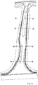
- Figure 1a schematically illustrates an example of a central beam of a B-pillar according to an implementation.
- lines A-A, B-B, C-C and D-D are indicated.
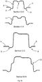
- Figure 1b schematically illustrates cross-sections of the example of the central beam of the B-pillar according to figure 1a along these lines.
- a central beam of a B-pillar such as the one illustrated in figure 1a may be made from an Ultra High Strength Steel, such as Usibor 1500.
- a hot stamping process may be used for its manufacturing.
- a so-called soft-zone (not further illustrated) may be provided along a portion of the beam.
- a soft zone is a portion of the beam that has increased ductility and deformability.
- a (central) B-pillar may generally comprise a central portion which widens both towards an upper end and towards a lower end. Such a central portion may extend along approximately 70% of the length of the B-pillar, whereas the wider lower end may extend along approximately 20% and the wider upper end may extend along approximately 10% of the length of the B-pillar. These wider portions are sometimes referred to as “lower gusset” and “upper gusset” respectively.
- figure 1b Several cross-sections at different heights of the beam of figure 1a are illustrated in figure 1b .
- the same reference signs have been used throughout the figures to indicate the same (or very similar) components. In order not to obscure all the drawings, not all reference signs have been repeated in each of the depicted cross-section.
- the beam may have a substantially U-shaped cross-section, wherein the "U” comprises a bottom portion 1, a first side wall 2, and a second side wall 3.
- the side walls may be substantially perpendicular to the bottom. Generally complete perpendicularity will not be achieved due to the need of removing the beam from a mold (or die).
- the first side wall 2 may comprise a first side portion 2a, and a second side portion 2b and a side transition zone 10 between the first and second side portions.
- the first side portion 2a extends from one end of the bottom portion towards the transition zone.
- the second side portion 2b extends from the transition zone towards a side flange 4.
- the second side wall 3 may have such first and second side portions 3a and 3b and a side transition zone 10 between them.
- Another side flange may be provided at the end of the second side wall 3.
- the side flanges 4 and 5 may be substantially parallel to the bottom portion 1.
- the side flanges may be provided in order to facilitate mounting of several items including e.g. an interior cover plate, i.e. a plate on the interior side or passenger side of the B-pillar.
- the side transition zone 10 along section D-D may comprise a substantially straight portion that is not parallel to the first and second side portions 2a and 2b, whereas these two side portions are substantially parallel.
- the side transition zone may thus be inclined (i.e. not horizontal), but with a different inclination than the first and second straight portions of the side wall. Similar arrangements may be seen in section A-A and section B-B.
- the bottom of the U-shape along section D-D comprises a stiffening rib in the form of an inwardly curved portion.
- Inwardly herein is to be understood as inwardly with respect to the U-shape.
- section A-A A different cross-section is shown for section A-A.
- the U-shaped cross-section is significantly wider than the cross-section for line D-D.
- the shape of the stiffening rib 7 may be different along section A-A.
- the side transition zones 11 in this case may comprise a first fillet radius 11a, and a second fillet radius 11b. In one practical example, such radii may be e.g. 5 mm each.
- the beam may have a substantially U-shaped cross-section, but the side walls 2 and 3 do not comprise any side transition zones.
- a portion of the central B-pillar may thus be adapted for the inclusion of a door lock.
- Such a door lock may require a substantially flat surface of side wall 2.
- each side transition zone may preferably be less than 20% of the width of the bottom of the U-shape and optionally may be from 5% - 15%, or approximately 10% or less of the width of the bottom of the U-shape. Width herein is defined as the dimension of the transition zone (and bottom) that is perpendicular to the height of the cross-section.
- the width of the bottom defined herein is the width between the connections of the bottom to the side walls.
- the side transition zone 12 in this case may comprise a first fillet radius 12a, a second fillet radius 12b and a substantially straight portion 12c in between. Such a substantially straight portion may be not parallel to either the bottom of the U or to the first and second side portions of the side walls.
- a B-pillar incorporating such a central beam as schematically illustrated in figure 1a and 1b may achieve a weight reduction as compared to a central beam that does not have the side transition zones, while satisfying the strength, stiffness and in particular deformation requirements and kinematic behavior.
- the deformation requirements under impact are particularly important for a B-pillar: as it deforms, it moves inwards, i.e. in the direction of the passengers. In order to improve safety for passengers, strict requirements as to how far inwards the beam is allowed to move have to be complied with. Movement of the beam inwards also means that energy of an impact is being absorbed. If more energy is absorbed by such a movement, less energy needs to be deformed by deformation and rupture.
- the side transition zones help e.g. a B-pillar to absorb high levels of energy while avoiding too much intrusion towards the passengers.
- the weight saving may be achieved by reducing the thickness of the beam, e.g. along portions of the beam. Patchwork blanks may be used accordingly.
- Another way in which weight saving may be obtained is that e.g. the portions of the beam along which an interior plate has to be provided may be reduced. For example, an interior plate may only need to be provided along an upper portion of the B-pillar and a lower portion of the B-pillar. This may have a further effect in that material use may be reduced.
- the height of the transition zone of the side walls has generally been indicated in sections D-D, A-A and B-B at substantially the same height, around 50% of the height, this does not necessarily need to be the case.
- the specific height of the side transition zones may be varied along the length of the beam.
- the side transition zones may be placed between 50 - 90 % of the height, in some cases between 60 - 80% of the height of the U-shape.
- 0% of the height is understood to be at the height of the side flanges (where the side flanges connect with the side walls) and 100% is to be understood as the height of the bottom portion of the U-shape.
- the side transition zones may be advantageous to provide the side transition zones closer to the bottom of the U-shape.
- the side walls buckle and the first side wall portion buckles inwards, it may make contact with the bottom portion of the U-shape and may thus support the bottom portion. This may improve the deformation behavior.
- Figure 1c schematically illustrates that a B-pillar in some examples may comprise a central beam 21, an external plate 22 and an internal plate 23.
- the internal plate 23 may serve for attaching parts of a car's interior.
- the external plate 22 may serve particularly for providing a complementary shape to a car door.
- Both an internal plate and an external plate may contribute to the structural strength and stiffness of the resulting B-pillar.
- Figure 2a schematically illustrates another example of a central beam of a B-pillar according to an implementation. Various cross-sections along the lines indicated in figure 2a are shown in figure 2b .
- a flange transition zone 8 is provided between a substantially straight portion of side flanges 4 and 5 and the first and second side walls respectively.
- the side walls may extend beyond the side flanges 4 and 5.
- Such a flange transition zone may comprise a concavity that is open towards the bottom portion of the U-shape.
- Similar flange transition zones may be provided along sections A-A, C-C and B-B. Again, the width of the transition zone may generally be 10% or less of the width of the bottom of the U-shape. For each of these sections, the moment of inertia around the neutral bending axis may be changed and the behavior under a bending moment can thus be improved.
- the weight of the U-beam may be significantly reduced.
- a synergistic effect is provided by the combination of the flange transition zones and the side transition zones, as the side transition zones enable redistributing resistance to bending moments over different cross-sections. Due to the flange transition zones, the height of the side walls increases, which would make the side walls more prone to buckling. The side transition zones compensate for this. A resulting B-pillar may thus have a reduced weight.
- a beam thus comprises a first portion with substantially U-shaped cross-section with side transition zones, a second portion having a U-shaped cross-section wherein the side walls do not have a side transition zone (around section C-C), and a third portion with substantially U-shaped cross-section with side transition zones.
- Figure 3a schematically illustrates another example of a central beam of a B-pillar according to another implementation. Various cross-sections along the lines indicated in figure 3a are shown in figure 3b .
- the sections A-A, B-B, C-C and D-D of figure 2b are generally quite comparable to the sections shown in previous figures. However, contrary to previous examples, the bottom portion of the U-shaped cross-sections C-C and B-B in this case may comprise a stiffening rib.
- section C-C wherein the side walls also incorporate side transition zones.
- the side walls did not incorporate such transition zones, because a substantially flat side wall was necessary for mounting a car door lock.
- the current example serves to illustrate that depending on the specific implementation, and e.g. depending on the precise position of a door lock, variations are possible.
- Figure 3c schematically illustrates other possible cross-sections for a central beam of a B-pillar that is comparable to the beam illustrated in figure 3a .
- D-D and A-A of figure 3c it may be seen that these substantially U-shaped cross-sections do not incorporate side transition zones.
- Sections C-C and D-D do however incorporate transition zones in their side walls.
- the incorporation of side transition zones along a portion of the lower half of the B-pillar has particularly advantageous effects.
- the B-pillar may have substantially U-shaped cross-sections with higher side walls than along the upper half. These side walls may thus be more prone to buckling. For this reason, a side transition zone along the highest cross-sections is most effective for improving the deformation and kinematic behavior.
- side transition zones may be incorporated at least along a lower half of the central portion of the central B-pillar, i.e. between a lower widening portion (generally referred to as "gusset") of the central B-pillar and about 50% of the height of the B-pillar.
- the side transition zones may be incorporated at least along a portion extending at least between approximately 20% and approximately 50% of the height of the B-pillar, i.e. extending from a lower gusset up to half the height of the B-pillar.
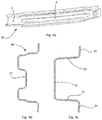
- FIG 4a schematically illustrates a three-dimensional view of a bumper beam 30.
- Bumper beams may also have a substantially U-shaped cross-section.
- the cross-section is illustrated as an open section, but in other implementations, such a U-shape may be closed by an additional plate extending at least between the side flanges of the U-shape.
- FIG. 4a Central portion A and side portion B are schematically illustrated in figure 4a.
- Figure 4b illustrates a cross-sectional view of a central portion A
- figure 4c illustrates a cross-sectional view of a side portion B.
- a bottom portion 31, a first side wall 32, a second side wall 33, and side flanges 34 and 35 are illustrated.
- the side walls do not incorporate side transition zones.
- a central portion of the bumper beam does incorporate a side transition zone 40.
- the side transition zone 40 may be arranged at a height between 50 - 80 %, particularly around a height of 70%.
- 0% of the height is understood to be at the height of the side flanges and 100% is to be understood as the height of the bottom portion of the U-shape.
- the side transition zones in a bumper beam may generally have similar advantageous effects in a bumper beam as in a B-pillar.
- a stiffening rib inwards protrusion of the bottom portion 31 along a central portion of the bumper beam.
- All illustrated examples of beams may advantageously be manufactured using hot stamping techniques.
- the cross-sections of the beams vary along their length, preferably in a substantially continuous manner.
- the non-constant cross-section along the length of the beam makes them particularly suitable for stamping.
- examples of beams have only been shown in connection with a B-pillar and in connection with a bumper beam.
- similar effects and advantages may be obtained when examples are implemented in other structural parts, such as e.g. a rocker panel, or a side impact beam.
- the side transition zones as described in examples may preferably be provided along a stretch of at least 10% or at least 20% of the length of the beam of the structural part in question in order to significantly influence the buckling behaviour of the side walls.
Landscapes
- Engineering & Computer Science (AREA)
- Mechanical Engineering (AREA)
- Chemical & Material Sciences (AREA)
- Combustion & Propulsion (AREA)
- Transportation (AREA)
- Body Structure For Vehicles (AREA)
- Vibration Dampers (AREA)
- Rod-Shaped Construction Members (AREA)
- Joining Of Building Structures In Genera (AREA)
- Golf Clubs (AREA)
- Looms (AREA)
Claims (16)
- Ein Träger umfassend einen ersten Teil, der ein im Wesentlichen U-förmiges Profil hat, wobei die U-Form einen Boden (1) und eine erste und eine zweite Seitenwand (2, 3) umfasst, und wobei
die erste und/oder die zweite Seitenwand (2,3) einen ersten im Wesentlichen geraden Teil (2a; 3a), einen zweiten im Wesentlichen geraden Teil (2b; 3b) und einen Seitenübergangsbereich (10; 11; 12) zwischen dem ersten und dem zweiten im Wesentlichen geraden Teil umfasst, dadurch gekennzeichnet, dass
der Seitenübergangsbereich (10; 11; 12) auf zwischen 50 - 90% einer Höhe der Seitenwand angeordnet ist, und wobei
der Seitenübergangsbereich (12) einen im Wesentlichen geraden Teil (12c) umfasst und wobei der erste (2a) und der zweite (2b) im Wesentlichen gerade Teil der Seitenwand im Wesentlichen parallel sind und der Seitenübergangsbereich nicht parallel zu dem ersten und dem zweiten im Wesentlichen geraden Teil sind, und wobei
der gerade Teil des Seitenübergangsbereichs geneigt bezüglich des Bodens der U-Form ist. - Ein Träger nach Anspruch 1, wobei das U-förmige Profil weiterhin einen ersten Seitenflansch (4) umfasst, der sich von der ersten Seitenwand heraus erstreckt, und/oder einen zweiten Seitenflansch (5) umfasst, der sich von der zweiten Seitenwand heraus erstreckt.
- Ein Träger nach Anspruch 2, wobei der erste und/oder der zweite Seitenflansch im Wesentlichen parallel zum Boden sind.
- Ein Träger nach Anspruch 2 oder 3, wobei der erste und/oder der zweite Seitenflansch einen Flanschübergangsbereich (8) umfassen.
- Ein Träger nach einem der Ansprüche 1 - 4, wobei der Seitenübergangsbereich (11; 12) einen ersten Rundungsradius (11a; 12a) an einem Ende des ersten im Wesentlichen geraden Teils (2a) und einen zweiten Rundungsradius (11b; 12b) an einem Ende des zweiten im Wesentlichen geraden Teils (2b) umfasst.
- Ein Träger nach einem der Ansprüche 1 - 5, wobei der Seitenübergangsbereich auf zwischen 50 - 80 % einer Höhe von einer Seitenwand angeordnet ist.
- Ein Träger nach Anspruch 6, wobei der Seitenübergangsbereich auf zwischen 50 - 70%, oder auf zwischen 60 - 80% der Höhe von einer Seitenwand angeordnet ist.
- Ein Träger nach Anspruch 7, wobei der Seitenübergangsbereich auf ca. 70% der Höhe von der Seitenwand angeordnet ist.
- Ein Träger nach einem der Ansprüche 1 - 8, wobei der Boden eine Versteifungsrippe umfasst, und wahlweise wobei die Versteifungsrippe einen Teil umfasst, der nach innen gekrümmt ist.
- Ein Träger nach einem der Ansprüche 1 - 9, weiterhin umfassend einen zweiten Teil, der ein U-förmiges Profil hat, wobei die U-Form einen Boden umfasst und eine erste und eine zweite Seitenwand umfasst, die sich im Wesentlichen senkrecht zum Boden erstrecken, wobei die Seitenwände keinen Seitenübergangsbereich haben.
- Ein Träger nach Anspruch 10, wobei sich der erste Teil entlang mindestens 10% oder entlang mindestens 20% der Länge des Trägers erstreckt.
- Ein Träger nach Anspruch 10 oder 11, weiterhin umfassend einen dritten Teil, der ein U-förmiges Profil hat, wobei die U-Form einen Boden umfasst und eine erste und eine zweite Seitenwand umfasst, die sich im Wesentlichen senkrecht zum Boden erstrecken, und wobei
die erste und/oder die zweite Seitenwand einen ersten im Wesentlichen geraden Teil, einen zweiten im Wesentlichen geraden Teil und einen Seitenübergangsbereich zwischen dem ersten und dem zweiten im Wesentlichen geraden Teil umfasst. - Ein Träger nach Anspruch 12, wobei sich der dritte Teil entlang mindestens 10% oder entlang mindestens 20% der Länge des Trägers erstreckt.
- Eine B-Säule umfassend einen mittleren Träger nach einem der Ansprüche 1 -13.
- Eine B-Säule nach Anspruch 13, wobei eine tiefere Hälfte des mittleren Trägers den ersten Teil (B-B) umfasst.
- Eine Stoßstange (30) umfassend einen Träger nach einem der Ansprüche 1 -13.
Priority Applications (2)
| Application Number | Priority Date | Filing Date | Title |
|---|---|---|---|
| PL14799145T PL3068678T3 (pl) | 2013-11-15 | 2014-11-14 | Belki o u-kształtnym przekroju poprzecznym |
| EP14799145.9A EP3068678B1 (de) | 2013-11-15 | 2014-11-14 | Träger mit u-förmigem profil |
Applications Claiming Priority (4)
| Application Number | Priority Date | Filing Date | Title |
|---|---|---|---|
| FR1361220 | 2013-11-15 | ||
| EP14382133 | 2014-04-07 | ||
| EP14799145.9A EP3068678B1 (de) | 2013-11-15 | 2014-11-14 | Träger mit u-förmigem profil |
| PCT/EP2014/074607 WO2015071412A1 (en) | 2013-11-15 | 2014-11-14 | Beams with u-shaped cross-section |
Publications (2)
| Publication Number | Publication Date |
|---|---|
| EP3068678A1 EP3068678A1 (de) | 2016-09-21 |
| EP3068678B1 true EP3068678B1 (de) | 2018-07-18 |
Family
ID=51900451
Family Applications (2)
| Application Number | Title | Priority Date | Filing Date |
|---|---|---|---|
| EP14799145.9A Active EP3068678B1 (de) | 2013-11-15 | 2014-11-14 | Träger mit u-förmigem profil |
| EP14798889.3A Not-in-force EP3068677B1 (de) | 2013-11-15 | 2014-11-14 | Träger zur herstellung eines metallgerüsts |
Family Applications After (1)
| Application Number | Title | Priority Date | Filing Date |
|---|---|---|---|
| EP14798889.3A Not-in-force EP3068677B1 (de) | 2013-11-15 | 2014-11-14 | Träger zur herstellung eines metallgerüsts |
Country Status (10)
| Country | Link |
|---|---|
| US (3) | US9849916B2 (de) |
| EP (2) | EP3068678B1 (de) |
| JP (1) | JP6313444B2 (de) |
| KR (1) | KR101935753B1 (de) |
| CN (2) | CN105722746B (de) |
| ES (2) | ES2691965T3 (de) |
| PL (1) | PL3068678T3 (de) |
| PT (1) | PT3068678T (de) |
| TR (1) | TR201815525T4 (de) |
| WO (2) | WO2015071412A1 (de) |
Families Citing this family (21)
| Publication number | Priority date | Publication date | Assignee | Title |
|---|---|---|---|---|
| WO2015071412A1 (en) | 2013-11-15 | 2015-05-21 | Autotech Engineering A.I.E. | Beams with u-shaped cross-section |
| CN107922010B (zh) * | 2015-08-20 | 2020-06-16 | 日本制铁株式会社 | 钢板部件组合构造、汽车用构造部件、中柱、保险杠及门横梁 |
| US10633031B2 (en) * | 2015-12-18 | 2020-04-28 | Autotech Engineering S.L. | B-pillar central beam and method for manufacturing |
| EP3390204B1 (de) | 2015-12-18 | 2019-10-02 | Autotech Engineering S.L. | Stützbalken mit abdeckplatte und verfahren zur herstellung |
| DE102016118366A1 (de) | 2016-09-28 | 2018-03-29 | Bayerische Motoren Werke Ag | Strukturbauteil für eine kraftfahrzeugkarosserie |
| JP6638634B2 (ja) * | 2016-12-08 | 2020-01-29 | トヨタ自動車株式会社 | 車両側部構造 |
| DE102016124100A1 (de) * | 2016-12-12 | 2018-06-14 | Benteler Automobiltechnik Gmbh | Achs- oder Fahrwerksbauteil für ein Kraftfahrzeug |
| JP6658493B2 (ja) | 2016-12-19 | 2020-03-04 | トヨタ自動車株式会社 | 車両側部構造 |
| JP6673262B2 (ja) * | 2017-02-27 | 2020-03-25 | トヨタ自動車株式会社 | 車両側部構造 |
| JP6555303B2 (ja) * | 2017-07-28 | 2019-08-07 | マツダ株式会社 | 車両の側部車体構造 |
| JP6941579B2 (ja) * | 2018-03-29 | 2021-09-29 | アイシン高丘株式会社 | 車体部品 |
| CN110466616A (zh) * | 2018-05-11 | 2019-11-19 | 宝沃汽车(中国)有限公司 | 用于车辆的立柱内板及车辆 |
| JP7200551B2 (ja) * | 2018-08-31 | 2023-01-10 | スズキ株式会社 | ハット型部材及びハット型部材の製造方法 |
| PT3867127T (pt) | 2018-10-15 | 2024-07-30 | Autotech Eng Sl | Perfil para uma viga estrutural de um veículo |
| CN109455226A (zh) * | 2018-11-23 | 2019-03-12 | 北京宏瑞汽车科技股份有限公司 | 一种纯电动车车架结构 |
| KR102644571B1 (ko) * | 2019-05-13 | 2024-03-06 | 현대자동차주식회사 | 차체 보강 장치 |
| CN112676416B (zh) * | 2019-10-17 | 2023-05-05 | 本田技研工业株式会社 | 车身骨架构件的制造方法 |
| JP7200167B2 (ja) * | 2020-04-16 | 2023-01-06 | 豊田鉄工株式会社 | 車両用強度部材 |
| FR3111320A1 (fr) * | 2020-06-16 | 2021-12-17 | Psa Automobiles Sa | Renfort de longeron pour véhicule automobile |
| JP2022152413A (ja) * | 2021-03-29 | 2022-10-12 | 本田技研工業株式会社 | 車体側部構造 |
| FR3154970A1 (fr) * | 2023-11-02 | 2025-05-09 | Stellantis Auto Sas | Tôle renforcée pour montant de carrosserie. |
Family Cites Families (46)
| Publication number | Priority date | Publication date | Assignee | Title |
|---|---|---|---|---|
| JPS5841671U (ja) | 1981-09-16 | 1983-03-18 | 三菱自動車工業株式会社 | 車両のピラ−構造 |
| JPH0456688A (ja) | 1990-06-23 | 1992-02-24 | Mazda Motor Corp | 自動車の下部車体構造 |
| JPH0796857A (ja) | 1993-09-28 | 1995-04-11 | Toyota Motor Corp | センタピラー構造 |
| JPH08188174A (ja) * | 1995-01-11 | 1996-07-23 | Nissan Diesel Motor Co Ltd | 車両の衝突緩衝装置 |
| KR20010049950A (ko) * | 1999-08-05 | 2001-06-15 | 제임스 이. 미러 | 차체의 프레임구조 |
| EP1227968B1 (de) * | 1999-10-28 | 2004-01-14 | Toyota Jidosha Kabushiki Kaisha | Struktur einer säule für kraftfahrzeuge |
| DE10007358A1 (de) * | 2000-02-18 | 2001-08-23 | Volkswagen Ag | Karosseriestruktur für ein Kraftfahrzeug |
| US6419302B2 (en) * | 2000-03-10 | 2002-07-16 | Toyota Jidosha Kabushiki Kaisha | Channel member for constructing elongated wall portion of vehicle body |
| KR100345692B1 (ko) | 2000-09-20 | 2002-07-27 | 기아자동차주식회사 | 차량의 센터필러 |
| KR100392086B1 (ko) * | 2000-11-24 | 2003-07-23 | 현대자동차주식회사 | 차량의 카울 사이드부 t형 박스구조 |
| US8033070B2 (en) | 2001-06-29 | 2011-10-11 | M.I.C. Industries, Inc. | Building panel and panel crimping machine |
| JP4057846B2 (ja) | 2002-06-07 | 2008-03-05 | 株式会社アステア | バンパ構造材 |
| DE10332633B4 (de) * | 2003-07-18 | 2007-10-25 | Audi Ag | Tragsäule für einen Fahrzeug-Karosserierahmen |
| US6986536B1 (en) * | 2004-06-25 | 2006-01-17 | Shape Corporation | Vehicle bumper beam |
| US7857377B2 (en) * | 2006-10-09 | 2010-12-28 | Ford Global Technologies, Llc | Tubular B-pillar to stamped rocker joint and method of assembling the same |
| JP4535084B2 (ja) * | 2007-05-10 | 2010-09-01 | トヨタ自動車株式会社 | 構造部材の断面構造 |
| JP5131065B2 (ja) * | 2008-07-14 | 2013-01-30 | トヨタ自動車株式会社 | 車両のピラー構造及びその製造方法。 |
| JP5041064B2 (ja) * | 2008-12-01 | 2012-10-03 | トヨタ自動車株式会社 | 車両側部構造 |
| KR20110008760A (ko) | 2009-07-21 | 2011-01-27 | 현대자동차주식회사 | 센터 필러 구조 |
| DE102009047956A1 (de) | 2009-10-01 | 2011-04-07 | Daimler Ag | Säule für einen Kraftwagen |
| SE533528C2 (sv) * | 2009-12-13 | 2010-10-19 | Gestamp Hardtech Ab | B-stolpe för fordon |
| CN102198843B (zh) * | 2010-03-23 | 2013-02-20 | 本田技研工业株式会社 | 车身侧部构造 |
| JP5459029B2 (ja) | 2010-04-08 | 2014-04-02 | トヨタ自動車株式会社 | 車両用のピラー構造および車両用ピラー製造方法 |
| JP5120409B2 (ja) * | 2010-04-13 | 2013-01-16 | トヨタ自動車株式会社 | 車両用センターピラー |
| DE102010036450B9 (de) | 2010-07-16 | 2020-09-03 | Thyssenkrupp Steel Europe Ag | B-Säulenverstärkung eines Kraftfahrzeugs |
| KR101210086B1 (ko) * | 2010-11-12 | 2012-12-07 | 현대자동차주식회사 | 아우터 어퍼센터필러 레인포스와 시트벨트 브래킷의 결합구조 |
| JP2012136190A (ja) | 2010-12-27 | 2012-07-19 | Toyota Motor Corp | 車両用センターピラー |
| KR101370729B1 (ko) | 2011-01-26 | 2014-03-06 | 도요타지도샤가부시키가이샤 | 센터 필러 상부 결합 구조 |
| US20120256445A1 (en) * | 2011-04-05 | 2012-10-11 | Ridha Baccouche | Vehicle roof support pillar |
| JP2013091458A (ja) * | 2011-10-26 | 2013-05-16 | Toyota Motor East Japan Inc | センターピラー構造 |
| DE102011120519A1 (de) * | 2011-12-08 | 2013-06-13 | GM Global Technology Operations LLC (n. d. Gesetzen des Staates Delaware) | Verstärkung für eine Fahrzeugsäule, insbesodnere die B-Säule eines Fahrzeuges |
| US8491047B1 (en) * | 2012-01-23 | 2013-07-23 | Nissan North America, Inc. | Vehicle body structure |
| JP5935494B2 (ja) * | 2012-05-08 | 2016-06-15 | マツダ株式会社 | 車両用フレーム構造 |
| JP5929594B2 (ja) * | 2012-07-30 | 2016-06-08 | マツダ株式会社 | 車体の側部構造 |
| WO2015071412A1 (en) * | 2013-11-15 | 2015-05-21 | Autotech Engineering A.I.E. | Beams with u-shaped cross-section |
| ES2853490T3 (es) * | 2014-02-17 | 2021-09-16 | Gestamp Hardtech Ab | Una soldadura alargada y una viga que incluye dicha soldadura |
| JP5975058B2 (ja) * | 2014-04-15 | 2016-08-23 | トヨタ自動車株式会社 | ピラー構造及び車両側部構造 |
| US9718966B2 (en) * | 2014-07-15 | 2017-08-01 | E I Du Pont De Nemours And Company | Polymer thick film silver conductor with inverted cure profile behavior |
| DE102014110320B4 (de) * | 2014-07-22 | 2016-11-24 | Benteler Automobiltechnik Gmbh | Verfahren zur Herstellung eines Leichtmetall Blechbauteils |
| JP6172079B2 (ja) * | 2014-07-24 | 2017-08-02 | マツダ株式会社 | 自動車の側部車体構造 |
| JP6344126B2 (ja) * | 2014-08-05 | 2018-06-20 | スズキ株式会社 | センターピラー構造 |
| JP6384203B2 (ja) * | 2014-08-29 | 2018-09-05 | スズキ株式会社 | 車両用センターピラー |
| US9616935B2 (en) * | 2014-10-10 | 2017-04-11 | Toyota Motor Engineering & Manufacturing North America, Inc. | Vehicle structures and methods of assembling the same |
| DE102015106812B4 (de) * | 2015-04-30 | 2018-11-08 | Benteler Automobiltechnik Gmbh | Kraftfahrzeugsäule mit Verstärkungsblech sowie Verfahren zu dessen Herstellung |
| JP6306543B2 (ja) * | 2015-08-05 | 2018-04-04 | トヨタ自動車株式会社 | 車両側部構造 |
| DE102016114062B3 (de) * | 2016-07-29 | 2017-06-22 | Benteler Automobiltechnik Gmbh | Säule für ein Kraftfahrzeug und Verfahren zur Herstellung einer Säule |
-
2014
- 2014-11-14 WO PCT/EP2014/074607 patent/WO2015071412A1/en not_active Ceased
- 2014-11-14 KR KR1020187002193A patent/KR101935753B1/ko active Active
- 2014-11-14 US US15/035,207 patent/US9849916B2/en active Active
- 2014-11-14 CN CN201480062506.3A patent/CN105722746B/zh not_active Expired - Fee Related
- 2014-11-14 EP EP14799145.9A patent/EP3068678B1/de active Active
- 2014-11-14 US US15/035,706 patent/US10023237B2/en not_active Expired - Fee Related
- 2014-11-14 ES ES14799145.9T patent/ES2691965T3/es active Active
- 2014-11-14 PL PL14799145T patent/PL3068678T3/pl unknown
- 2014-11-14 ES ES14798889T patent/ES2715380T3/es active Active
- 2014-11-14 JP JP2016530913A patent/JP6313444B2/ja active Active
- 2014-11-14 CN CN201480061906.2A patent/CN105722745B/zh active Active
- 2014-11-14 EP EP14798889.3A patent/EP3068677B1/de not_active Not-in-force
- 2014-11-14 WO PCT/EP2014/074689 patent/WO2015071444A2/fr not_active Ceased
- 2014-11-14 PT PT14799145T patent/PT3068678T/pt unknown
- 2014-11-14 TR TR2018/15525T patent/TR201815525T4/tr unknown
-
2017
- 2017-11-17 US US15/816,985 patent/US10279844B2/en active Active
Non-Patent Citations (1)
| Title |
|---|
| None * |
Also Published As
| Publication number | Publication date |
|---|---|
| TR201815525T4 (tr) | 2018-11-21 |
| CN105722746A (zh) | 2016-06-29 |
| JP6313444B2 (ja) | 2018-04-18 |
| ES2715380T3 (es) | 2019-06-04 |
| EP3068677A2 (de) | 2016-09-21 |
| WO2015071444A2 (fr) | 2015-05-21 |
| EP3068677B1 (de) | 2019-01-09 |
| PT3068678T (pt) | 2018-11-22 |
| US10279844B2 (en) | 2019-05-07 |
| US20180072350A1 (en) | 2018-03-15 |
| CN105722745A (zh) | 2016-06-29 |
| US20160280270A1 (en) | 2016-09-29 |
| US10023237B2 (en) | 2018-07-17 |
| WO2015071412A1 (en) | 2015-05-21 |
| CN105722745B (zh) | 2018-10-26 |
| JP2016540678A (ja) | 2016-12-28 |
| US20160288840A1 (en) | 2016-10-06 |
| EP3068678A1 (de) | 2016-09-21 |
| WO2015071444A3 (fr) | 2015-09-24 |
| PL3068678T3 (pl) | 2019-03-29 |
| CN105722746B (zh) | 2018-06-01 |
| KR20180014177A (ko) | 2018-02-07 |
| US9849916B2 (en) | 2017-12-26 |
| KR101935753B1 (ko) | 2019-01-04 |
| ES2691965T3 (es) | 2018-11-29 |
Similar Documents
| Publication | Publication Date | Title |
|---|---|---|
| US10279844B2 (en) | Beams with U-shaped cross-section | |
| US9555835B2 (en) | Body structure, in particular floor structure, for a motor vehicle | |
| RU2718651C2 (ru) | Центральная балка центральной стойки кузова и способ ее изготовления | |
| JP5894081B2 (ja) | 車両用bピラー | |
| EP2424769B1 (de) | Energieabsorbierende seitenschiene für ein fahrzeug | |
| JP2023531973A (ja) | 車両用ロッカー補強材及びロッカー | |
| US20240262425A1 (en) | Structural members for a vehicle and methods | |
| KR20160070828A (ko) | U형상 횡단면을 갖는 빔 | |
| JP2025532331A (ja) | 車両のための一体型後部レール構造および方法 | |
| EP4590452A1 (de) | Strukturkomponenten für ein fahrzeug und verfahren | |
| CN110087977B (zh) | 用于车厢的后面的加强结构 | |
| WO2025125596A1 (en) | Reinforcement for vehicle door and methods of manufacture | |
| CN120153100A (zh) | 用于车辆的结构部件及方法 | |
| BR112018010480B1 (pt) | Viga central de pilar-b e seu método de fabricação |
Legal Events
| Date | Code | Title | Description |
|---|---|---|---|
| PUAI | Public reference made under article 153(3) epc to a published international application that has entered the european phase |
Free format text: ORIGINAL CODE: 0009012 |
|
| 17P | Request for examination filed |
Effective date: 20160615 |
|
| AK | Designated contracting states |
Kind code of ref document: A1 Designated state(s): AL AT BE BG CH CY CZ DE DK EE ES FI FR GB GR HR HU IE IS IT LI LT LU LV MC MK MT NL NO PL PT RO RS SE SI SK SM TR |
|
| AX | Request for extension of the european patent |
Extension state: BA ME |
|
| RIN1 | Information on inventor provided before grant (corrected) |
Inventor name: VALENCIA CARRIO, XAVIER Inventor name: ESPANA DE JUAN, LLUIS Inventor name: LEROY, EMMANUEL Inventor name: NIESS, MATTHIEU Inventor name: DUNAND, MATTHIEU Inventor name: CAZES, CHRISTOPHE Inventor name: GATARD, GREGORY Inventor name: BARELLI, VINCENT Inventor name: MARQUEZ DURAN, SERGI |
|
| DAX | Request for extension of the european patent (deleted) | ||
| GRAP | Despatch of communication of intention to grant a patent |
Free format text: ORIGINAL CODE: EPIDOSNIGR1 |
|
| STAA | Information on the status of an ep patent application or granted ep patent |
Free format text: STATUS: GRANT OF PATENT IS INTENDED |
|
| INTG | Intention to grant announced |
Effective date: 20180424 |
|
| GRAS | Grant fee paid |
Free format text: ORIGINAL CODE: EPIDOSNIGR3 |
|
| GRAA | (expected) grant |
Free format text: ORIGINAL CODE: 0009210 |
|
| STAA | Information on the status of an ep patent application or granted ep patent |
Free format text: STATUS: THE PATENT HAS BEEN GRANTED |
|
| AK | Designated contracting states |
Kind code of ref document: B1 Designated state(s): AL AT BE BG CH CY CZ DE DK EE ES FI FR GB GR HR HU IE IS IT LI LT LU LV MC MK MT NL NO PL PT RO RS SE SI SK SM TR |
|
| REG | Reference to a national code |
Ref country code: GB Ref legal event code: FG4D |
|
| REG | Reference to a national code |
Ref country code: CH Ref legal event code: EP |
|
| REG | Reference to a national code |
Ref country code: IE Ref legal event code: FG4D |
|
| REG | Reference to a national code |
Ref country code: AT Ref legal event code: REF Ref document number: 1019021 Country of ref document: AT Kind code of ref document: T Effective date: 20180815 |
|
| REG | Reference to a national code |
Ref country code: DE Ref legal event code: R096 Ref document number: 602014028805 Country of ref document: DE |
|
| REG | Reference to a national code |
Ref country code: NL Ref legal event code: MP Effective date: 20180718 |
|
| REG | Reference to a national code |
Ref country code: PT Ref legal event code: SC4A Ref document number: 3068678 Country of ref document: PT Date of ref document: 20181122 Kind code of ref document: T Free format text: AVAILABILITY OF NATIONAL TRANSLATION Effective date: 20181108 Ref country code: RO Ref legal event code: EPE |
|
| REG | Reference to a national code |
Ref country code: ES Ref legal event code: FG2A Ref document number: 2691965 Country of ref document: ES Kind code of ref document: T3 Effective date: 20181129 |
|
| REG | Reference to a national code |
Ref country code: LT Ref legal event code: MG4D |
|
| REG | Reference to a national code |
Ref country code: AT Ref legal event code: MK05 Ref document number: 1019021 Country of ref document: AT Kind code of ref document: T Effective date: 20180718 |
|
| PG25 | Lapsed in a contracting state [announced via postgrant information from national office to epo] |
Ref country code: NL Free format text: LAPSE BECAUSE OF FAILURE TO SUBMIT A TRANSLATION OF THE DESCRIPTION OR TO PAY THE FEE WITHIN THE PRESCRIBED TIME-LIMIT Effective date: 20180718 |
|
| PG25 | Lapsed in a contracting state [announced via postgrant information from national office to epo] |
Ref country code: NO Free format text: LAPSE BECAUSE OF FAILURE TO SUBMIT A TRANSLATION OF THE DESCRIPTION OR TO PAY THE FEE WITHIN THE PRESCRIBED TIME-LIMIT Effective date: 20181018 Ref country code: BG Free format text: LAPSE BECAUSE OF FAILURE TO SUBMIT A TRANSLATION OF THE DESCRIPTION OR TO PAY THE FEE WITHIN THE PRESCRIBED TIME-LIMIT Effective date: 20181018 Ref country code: IS Free format text: LAPSE BECAUSE OF FAILURE TO SUBMIT A TRANSLATION OF THE DESCRIPTION OR TO PAY THE FEE WITHIN THE PRESCRIBED TIME-LIMIT Effective date: 20181118 Ref country code: RS Free format text: LAPSE BECAUSE OF FAILURE TO SUBMIT A TRANSLATION OF THE DESCRIPTION OR TO PAY THE FEE WITHIN THE PRESCRIBED TIME-LIMIT Effective date: 20180718 Ref country code: LT Free format text: LAPSE BECAUSE OF FAILURE TO SUBMIT A TRANSLATION OF THE DESCRIPTION OR TO PAY THE FEE WITHIN THE PRESCRIBED TIME-LIMIT Effective date: 20180718 Ref country code: AT Free format text: LAPSE BECAUSE OF FAILURE TO SUBMIT A TRANSLATION OF THE DESCRIPTION OR TO PAY THE FEE WITHIN THE PRESCRIBED TIME-LIMIT Effective date: 20180718 Ref country code: GR Free format text: LAPSE BECAUSE OF FAILURE TO SUBMIT A TRANSLATION OF THE DESCRIPTION OR TO PAY THE FEE WITHIN THE PRESCRIBED TIME-LIMIT Effective date: 20181019 Ref country code: FI Free format text: LAPSE BECAUSE OF FAILURE TO SUBMIT A TRANSLATION OF THE DESCRIPTION OR TO PAY THE FEE WITHIN THE PRESCRIBED TIME-LIMIT Effective date: 20180718 Ref country code: SE Free format text: LAPSE BECAUSE OF FAILURE TO SUBMIT A TRANSLATION OF THE DESCRIPTION OR TO PAY THE FEE WITHIN THE PRESCRIBED TIME-LIMIT Effective date: 20180718 |
|
| PG25 | Lapsed in a contracting state [announced via postgrant information from national office to epo] |
Ref country code: AL Free format text: LAPSE BECAUSE OF FAILURE TO SUBMIT A TRANSLATION OF THE DESCRIPTION OR TO PAY THE FEE WITHIN THE PRESCRIBED TIME-LIMIT Effective date: 20180718 Ref country code: HR Free format text: LAPSE BECAUSE OF FAILURE TO SUBMIT A TRANSLATION OF THE DESCRIPTION OR TO PAY THE FEE WITHIN THE PRESCRIBED TIME-LIMIT Effective date: 20180718 Ref country code: LV Free format text: LAPSE BECAUSE OF FAILURE TO SUBMIT A TRANSLATION OF THE DESCRIPTION OR TO PAY THE FEE WITHIN THE PRESCRIBED TIME-LIMIT Effective date: 20180718 |
|
| REG | Reference to a national code |
Ref country code: SK Ref legal event code: T3 Ref document number: E 29136 Country of ref document: SK |
|
| REG | Reference to a national code |
Ref country code: DE Ref legal event code: R097 Ref document number: 602014028805 Country of ref document: DE |
|
| PG25 | Lapsed in a contracting state [announced via postgrant information from national office to epo] |
Ref country code: EE Free format text: LAPSE BECAUSE OF FAILURE TO SUBMIT A TRANSLATION OF THE DESCRIPTION OR TO PAY THE FEE WITHIN THE PRESCRIBED TIME-LIMIT Effective date: 20180718 Ref country code: IT Free format text: LAPSE BECAUSE OF FAILURE TO SUBMIT A TRANSLATION OF THE DESCRIPTION OR TO PAY THE FEE WITHIN THE PRESCRIBED TIME-LIMIT Effective date: 20180718 |
|
| PLBE | No opposition filed within time limit |
Free format text: ORIGINAL CODE: 0009261 |
|
| STAA | Information on the status of an ep patent application or granted ep patent |
Free format text: STATUS: NO OPPOSITION FILED WITHIN TIME LIMIT |
|
| PG25 | Lapsed in a contracting state [announced via postgrant information from national office to epo] |
Ref country code: SM Free format text: LAPSE BECAUSE OF FAILURE TO SUBMIT A TRANSLATION OF THE DESCRIPTION OR TO PAY THE FEE WITHIN THE PRESCRIBED TIME-LIMIT Effective date: 20180718 Ref country code: DK Free format text: LAPSE BECAUSE OF FAILURE TO SUBMIT A TRANSLATION OF THE DESCRIPTION OR TO PAY THE FEE WITHIN THE PRESCRIBED TIME-LIMIT Effective date: 20180718 |
|
| 26N | No opposition filed |
Effective date: 20190423 |
|
| REG | Reference to a national code |
Ref country code: CH Ref legal event code: PL |
|
| PG25 | Lapsed in a contracting state [announced via postgrant information from national office to epo] |
Ref country code: LU Free format text: LAPSE BECAUSE OF NON-PAYMENT OF DUE FEES Effective date: 20181114 Ref country code: MC Free format text: LAPSE BECAUSE OF FAILURE TO SUBMIT A TRANSLATION OF THE DESCRIPTION OR TO PAY THE FEE WITHIN THE PRESCRIBED TIME-LIMIT Effective date: 20180718 |
|
| REG | Reference to a national code |
Ref country code: BE Ref legal event code: MM Effective date: 20181130 |
|
| REG | Reference to a national code |
Ref country code: IE Ref legal event code: MM4A |
|
| PG25 | Lapsed in a contracting state [announced via postgrant information from national office to epo] |
Ref country code: SI Free format text: LAPSE BECAUSE OF FAILURE TO SUBMIT A TRANSLATION OF THE DESCRIPTION OR TO PAY THE FEE WITHIN THE PRESCRIBED TIME-LIMIT Effective date: 20180718 Ref country code: CH Free format text: LAPSE BECAUSE OF NON-PAYMENT OF DUE FEES Effective date: 20181130 Ref country code: LI Free format text: LAPSE BECAUSE OF NON-PAYMENT OF DUE FEES Effective date: 20181130 |
|
| PG25 | Lapsed in a contracting state [announced via postgrant information from national office to epo] |
Ref country code: IE Free format text: LAPSE BECAUSE OF NON-PAYMENT OF DUE FEES Effective date: 20181114 |
|
| PG25 | Lapsed in a contracting state [announced via postgrant information from national office to epo] |
Ref country code: BE Free format text: LAPSE BECAUSE OF NON-PAYMENT OF DUE FEES Effective date: 20181130 |
|
| PG25 | Lapsed in a contracting state [announced via postgrant information from national office to epo] |
Ref country code: MT Free format text: LAPSE BECAUSE OF NON-PAYMENT OF DUE FEES Effective date: 20181114 |
|
| PGFP | Annual fee paid to national office [announced via postgrant information from national office to epo] |
Ref country code: PT Payment date: 20191021 Year of fee payment: 6 Ref country code: SK Payment date: 20191021 Year of fee payment: 6 Ref country code: CZ Payment date: 20191101 Year of fee payment: 6 Ref country code: HU Payment date: 20191031 Year of fee payment: 6 Ref country code: RO Payment date: 20191022 Year of fee payment: 6 |
|
| PGFP | Annual fee paid to national office [announced via postgrant information from national office to epo] |
Ref country code: PL Payment date: 20191022 Year of fee payment: 6 |
|
| PGFP | Annual fee paid to national office [announced via postgrant information from national office to epo] |
Ref country code: TR Payment date: 20191030 Year of fee payment: 6 |
|
| PG25 | Lapsed in a contracting state [announced via postgrant information from national office to epo] |
Ref country code: CY Free format text: LAPSE BECAUSE OF FAILURE TO SUBMIT A TRANSLATION OF THE DESCRIPTION OR TO PAY THE FEE WITHIN THE PRESCRIBED TIME-LIMIT Effective date: 20180718 Ref country code: MK Free format text: LAPSE BECAUSE OF NON-PAYMENT OF DUE FEES Effective date: 20180718 |
|
| REG | Reference to a national code |
Ref country code: SK Ref legal event code: MM4A Ref document number: E 29136 Country of ref document: SK Effective date: 20201114 |
|
| PG25 | Lapsed in a contracting state [announced via postgrant information from national office to epo] |
Ref country code: CZ Free format text: LAPSE BECAUSE OF NON-PAYMENT OF DUE FEES Effective date: 20201114 Ref country code: PT Free format text: LAPSE BECAUSE OF NON-PAYMENT OF DUE FEES Effective date: 20210517 Ref country code: SK Free format text: LAPSE BECAUSE OF NON-PAYMENT OF DUE FEES Effective date: 20201114 Ref country code: RO Free format text: LAPSE BECAUSE OF NON-PAYMENT OF DUE FEES Effective date: 20201114 |
|
| PG25 | Lapsed in a contracting state [announced via postgrant information from national office to epo] |
Ref country code: HU Free format text: LAPSE BECAUSE OF NON-PAYMENT OF DUE FEES Effective date: 20201115 |
|
| PG25 | Lapsed in a contracting state [announced via postgrant information from national office to epo] |
Ref country code: TR Free format text: LAPSE BECAUSE OF NON-PAYMENT OF DUE FEES Effective date: 20201114 |
|
| PG25 | Lapsed in a contracting state [announced via postgrant information from national office to epo] |
Ref country code: PL Free format text: LAPSE BECAUSE OF NON-PAYMENT OF DUE FEES Effective date: 20201114 |
|
| PGFP | Annual fee paid to national office [announced via postgrant information from national office to epo] |
Ref country code: FR Payment date: 20221123 Year of fee payment: 9 |
|
| PG25 | Lapsed in a contracting state [announced via postgrant information from national office to epo] |
Ref country code: FR Free format text: LAPSE BECAUSE OF NON-PAYMENT OF DUE FEES Effective date: 20231130 |
|
| PG25 | Lapsed in a contracting state [announced via postgrant information from national office to epo] |
Ref country code: FR Free format text: LAPSE BECAUSE OF NON-PAYMENT OF DUE FEES Effective date: 20231130 |
|
| PGFP | Annual fee paid to national office [announced via postgrant information from national office to epo] |
Ref country code: GB Payment date: 20241127 Year of fee payment: 11 |
|
| PGFP | Annual fee paid to national office [announced via postgrant information from national office to epo] |
Ref country code: DE Payment date: 20251128 Year of fee payment: 12 |
|
| PGFP | Annual fee paid to national office [announced via postgrant information from national office to epo] |
Ref country code: ES Payment date: 20251201 Year of fee payment: 12 |