EP3070209A1 - Corps de robinetterie pour une armature sanitaire et procede de fabrication - Google Patents
Corps de robinetterie pour une armature sanitaire et procede de fabrication Download PDFInfo
- Publication number
- EP3070209A1 EP3070209A1 EP16000557.5A EP16000557A EP3070209A1 EP 3070209 A1 EP3070209 A1 EP 3070209A1 EP 16000557 A EP16000557 A EP 16000557A EP 3070209 A1 EP3070209 A1 EP 3070209A1
- Authority
- EP
- European Patent Office
- Prior art keywords
- shell
- sub
- molding compound
- fitting
- fitting body
- Prior art date
- Legal status (The legal status is an assumption and is not a legal conclusion. Google has not performed a legal analysis and makes no representation as to the accuracy of the status listed.)
- Granted
Links
Images
Classifications
-
- E—FIXED CONSTRUCTIONS
- E03—WATER SUPPLY; SEWERAGE
- E03C—DOMESTIC PLUMBING INSTALLATIONS FOR FRESH WATER OR WASTE WATER; SINKS
- E03C1/00—Domestic plumbing installations for fresh water or waste water; Sinks
- E03C1/02—Plumbing installations for fresh water
- E03C1/04—Water-basin installations specially adapted to wash-basins or baths
- E03C1/0404—Constructional or functional features of the spout
Definitions
- the present invention relates to a fitting body for a sanitary fitting and a method for producing a fitting body for a sanitary fitting.
- the fitting body is in particular a part or a component of a sanitary fitting.
- Sanitary fittings are, in particular, thermostatic fittings and / or mixing fittings, in particular thermostatic mixing valves, for bathtubs, wall basins, hand showers or the like.
- the sanitary fittings regularly have a hot water supply for hot water and a cold water supply for cold water.
- the sanitary fittings regularly have an outlet opening for mixed water.
- the hot water and the cold water can be mixed within the sanitary fitting by means of a thermostatic valve to achieve a predeterminable water temperature.
- the water flow or the amount of water can be adjusted by means of a volume control valve.
- the valves can be actuated by means of separate actuators or by means of a common actuator.
- water fittings in which the water channels or the waterways are formed in a body.
- a base body is formed for example of metal, plastic or the like.
- the water channels are introduced during the manufacturing process, in particular during a casting process or injection molding, by means of appropriate molding tools in the body.
- the present invention has the object, at least partially solve the problems described with reference to the prior art.
- a fitting body for a sanitary fitting are specified, which is easy to manufacture, requires a small space and has as few sealing points.
- the Entform stresses to be facilitated and undercuts are avoided in Entformungscardi.
- the dashboard body should act in one piece from the outside.
- a manufacturing method for a fitting body is to be specified, which allows the simplest possible manufacture of a compact fitting body with as few sealing points or high density.
- a slight demolding of the individual components is to be made possible and undercuts are avoided.
- the present invention provides a fitting body for a sanitary fitting.
- the fitting body has an outer side, which is formed with at least a first partial shell and at least one second partial shell.
- the at least one first sub-shell and the at least one second sub-shell are arranged to match each other.
- At least one waterway is formed between the at least one first subshell and the at least one second subshell.
- the outside is predominantly covered by a molding compound.
- the outside of the fitting body is formed with the at least one first sub-shell and the at least one second sub-shell, wherein the sub-shells together form virtually the entire outer side (possibly excluding sensors, connections, openings, etc.).
- the outside is in this case on the side facing away from the at least one waterway side of the partial shells.
- the outer side can also be understood here as the outer surface of the partial shells.
- the fitting body is usually not visible from the outside in the fitting housing, so that the outside mentioned here is not basically equated with an outer surface of the sanitary fitting itself.
- the at least one first subshell and the at least one second subshell are each a half shell of the fitting body.
- An upper or lower half shell relates in particular to an upper or lower half of a fitting body. If the partial shells are formed as half-shells, then the separation or lie the separation surfaces of the half-shells in a plane, in particular a division plane or parting plane. Such a design
- upper and lower half-shell is not mandatory, because a plurality of first and / or second partial shells may be present, whereby the separating surfaces of the respective partial shells in several, in particular inclined to each other, levels.
- the subshells are arranged to match each other at their respective separation surfaces and / or interconnected. In this case, the separating surfaces may be brought into contact with one another, for example, and / or brought into a mold engagement by means of positioning elements, for example.
- At least one waterway is formed between the at least one first subshell and the at least one second subshell. In other words, this also means that the waterway is enclosed along the flow direction of the water by means of the partial shells.
- a plurality of water paths are provided which guide, for example, cold water, hot water and / or mixed water through the fitting body.
- the outside of the fitting body - after composite partial shells - is predominantly covered by a molding compound, ie in particular at least 70% or 80%. Very particular preference is that the outside is completely covered by the molding compound. In particular, all border areas of the two partial switching with each other (sealing surfaces) are detected. Preferably, the outside is almost completely covered with the molding compound, wherein openings of the fitting body, such as. B. inlet openings, outlet openings, connecting pieces or the like are not covered by the molding compound. In other words, this means in particular that the outer surface of the partial shells can also be (completely) covered by the molding compound.
- the at least one first subshell and the at least one second subshell are encapsulated with the molding compound.
- the partial shells, which were previously connected to one another are encapsulated in an injection molding tool by means of a liquid molding compound.
- the half shells are designed and connected together so that they the high injection pressure in Withstand injection mold and are tight against the liquid molding compound.
- the covering with the molding compound can advantageously take place as quickly as possible and in particular in series maturity.
- At least the at least one first subshell which is or are formed with at least one second subshell or the molding compound with a plastic or silicone.
- the subshells themselves can be formed by means of a casting process, in particular by means of an injection molding process. However, it is not mandatory that all shells are made of the same plastic.
- the molding compound is formed with or from a particularly firm or dimensionally stable plastic. This leads advantageously to the fact that the component strength of the fitting body is determined to a large extent by the molding material.
- the at least one first sub-shell and the at least one second sub-shell are connected to each other by means of a spring-groove connection.
- a spring-groove connection is, for example, formed with at least one groove in a parting surface of a second sub-shell and with at least one projection corresponding to the groove on an associated parting surface of a first sub-shell.
- the separating surfaces in each case relate to the contact surfaces or contact surfaces of contacting partial shells.
- the respective projection at least partially engages in the corresponding groove.
- a partial shell may have a plurality of grooves and / or projections.
- the spring-groove connection not only serves to form-fit the partial shells together, but also to seal the waterways between or within the subshells.
- a leak-tightness from the outside to the inside is required, which is necessary for the joining connected downstream process, the covering and in particular encapsulation with the molding compound.
- Such a downstream process can be carried out, for example, in a second tool mold, wherein the individual sub-shells can be previously cast in a first tool mold.
- the tightness of the joints of the partial shells for the later application in a sanitary fitting is of minor importance, because all outgoing sealing points are formed only when covering and especially during encapsulation with the molding compound.
- a spring-groove connection between the partial shells is not mandatory (to be provided alone), because the partial shells can also be joined by means of an adhesive bond or a material connection, in particular under the influence of heat.
- adhesive here compounds are referred to, in which the connection partners are held together by atomic or molecular forces.
- a cavity is formed in the region of an outlet opening of the at least one water path by means of the molding compound.
- the cavity extends beyond an end region of the at least one first partial shell and the at least one second partial shell.
- the cavity may also extend in a direction transverse to the conveying direction or flow direction of the water path via the outlet opening of the water path or over the end region of the partial shells addition. In other words, this means in particular that a diameter of the cavity is greater than a diameter of the waterway.
- a cross section of the waterway or the cavity is understood here essentially perpendicular to a flow direction or conveying direction of the waterway.
- the waterway and / or the cavity can be circular, oval or angular in cross section.
- the cavity is designed with at least one sealant or a connecting means.
- a connecting means can be designed here in the manner of a thread, by means of locking tongues or by means of at least one clip or the like.
- a sealant may be embodied here in the manner of an additional seal, such as, for example, an O-ring seal or a disk seal or the like.
- the cavity can also be regarded as a sealing region, wherein, for example, a projection formed with the molding compound extends further inwards from an inner circumference of the sealing region.
- the cavity may also be adapted to receive an insert formed with or made of metal or plastic.
- an insert can serve, for example, for connection to a valve or a water connection.
- Such an application can also and In particular, in a process step with the partial shells covered with the molding compound and preferably encapsulated.
- step a) the provision of the partial shells preferably takes place by means of a casting process, preferably by means of an injection molding process and very particularly preferably by means of a plastic injection molding process.
- the provision in step a) can take place in a first process step and in particular in a first tool mold.
- step b) the arranging or connecting of the partial shells takes place in particular by means of laying on and / or connecting the respective separating surfaces of the individual partial shells. If the partial shells are arranged aligned with each other, an outside of the fitting body is formed. This outside can also be considered the outer surface of the individual part shells be understood.
- the waterway is here formed by the fact that the sub-shells bound in the interior of a cavity, which is traversed by an inlet to an outlet of a water.
- step c) a predominant portion of the outside is covered with the molding compound.
- the outer surface of the partial shells is completely covered so that only the openings of the fitting body, in particular the water inlets, water outlets, valve connections or the like, are free of molding material.
- connection in step b) takes place by means of a spring-groove connection.
- a spring-groove connection is not mandatory, because the connection in step b) can also take place by means of an adhesive bond, or a cohesive connection, in particular by means of a welding operation.
- step c) at least a portion of the at least one first sub-shell and the at least one second sub-shell is overmolded with the molding compound.
- the encapsulation in step c) can be carried out in a second process step and in particular in a second mold.
- step c) a cavity is formed in the region of an outlet opening of the at least one waterway by means of the molding compound, wherein the cavity extends beyond an end region of the at least one first partial shell and the at least one second partial shell.
- the formation of the cavity and in particular of a sealing region can also take place here in a second process step and in particular in a second tool mold.
- all sealing points which make the fitting body releasably connectable to the outside or with external devices, are formed by means of the molding compound.
- the second mold is preferably formed as a plastic injection molding tool.
- the partial shells which are already connected to one another are furthermore preferably held and are injection-molded with the molding compound from the outside.
- the second tool shape can also be designed to allow an encapsulation of a cavity, which is upstream or downstream of the subshells in or against a flow direction of the waterway.
- the second tool shape for example, may include a casting core, an inner body corresponding to the cavity, or the like.
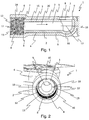
- Fig. 1 shows a fitting body 1 in a sectional view.
- the fitting body 1 has an outer side 2.
- the outer side 2 is here formed with a first partial shell 3 and a second partial shell 4. Since there are two subshells, the first subshell 3 is, for example, an upper half shell 15 and the second subshell 4 is a lower half shell 16.
- the first subshell 3 and the second subshell 4 are connected to one another at an interface 17.
- a waterway 5 is formed between the first sub-shell 3 and the second sub-shell 4, a waterway 5 is formed.
- the waterway 5 has two outlet openings 7. In the left part of the Fig. 1 is the outlet opening 7 to the left, and in the right part of the Fig. 1 the outlet opening 7 is directed upward. Whether or not the outlet 7 is an influence or outflow for water depends on the direction of flow of the water in the waterway 5.
- the outside 2 is predominantly covered by a molding compound 6.
- the first partial shell 3 and the second partial shell 4 are encapsulated with the molding compound.
- the molding compound 6 surrounds the outer surface of the upper half shell 15 and the lower half shell 16.
- the molding compound 6 allows a particularly homogeneous outer contour of the fitting body. 1
- first sub-shell 3 and the second sub-shell 4 are almost completely encapsulated with the molding compound, but the outlet openings 7 of the waterways 5 are not closed by the molding compound 6.
- the upper half shell 15 and the lower half shell 16 are each formed with plastic.
- the upper half shell 15 and the lower half shell 16 are produced in a plastic injection molding tool.
- the molding compound 6 is also formed here with plastic.
- the upper half-shell 15 and the lower half-shell 16 were overmolded in a connected state with the molding compound 6, namely the plastic.
- Fig. 1 It can also be seen that the separation of the upper half-shell 15 and the lower half-shell 16 lies in one plane. Thus, the separation surface 17 is formed in this plane.
- the upper half shell 15 and the lower half shell 16 are connected to each other by means of a tongue and groove connection 10.
- the Fig. 1 shows in the left area further that subsequently and / or in alignment with the outlet opening 7 of the waterway 5 by means of the molding compound 6, a cavity 8 is formed.
- the cavity 8 extends beyond an end region 9 of the first partial shell 3 and the second partial shell 4.
- an inner diameter of the cavity 8 is larger than an inner diameter of the waterway 5.
- the in Fig. 1 Cavity 8 shown on the left is designed with a sealing means 11 or a connecting means 12.
- the cavity 8 has an internal shaping in the manner of a thread 13.
- the left cavity 8 is also a sealing area 14.
- the cavity 8 extends beyond the outlet opening 7 and the end region 9.
- the inner diameter of the cavity 8 is greater than an inner diameter of the upwardly directed outlet opening 7 of the waterway 5. Due to this configuration can be realized that all outgoing or directed to an external device sealing points or joints by means of the molding compound. 6 are formed.
- Fig. 2 is a perspective view of the fitting body 1 for a sanitary fitting shown.
- the outside 2 of the fitting body is predominantly covered by the molding compound 6.
- the outer side 2 is formed with a first partial shell 3 and a second partial shell 4. Since two partial shells are provided here, the first subshell 3 is an upper half shroud 15 and the second subshell 4 is a lower half shroud 16 connected to its respective one Dividing surfaces 17 are interconnected.
- the connection of the upper half shell 15 and the lower half shell 16 by means of a tongue and groove connection 10.
- a tongue and groove connection 10 is shown.
- the spring-groove connection 10 extends along the parting surface 17 of the two partial shells.
- the upper half-shell 15 has a projection 18 on the left and on the right
- the lower half-shell 16 has a groove 19 on the left and on the right.
- the projections 18 engage in the grooves 19.
- the projections 18 and the grooves 19 extend here in or against a flow direction or propagation direction of the water path. 5
- FIG. 2 The perspective view of Fig. 2 is from the outside on the in Fig. 1 directed cavity 8 shown on the left.
- the cavity 8 is provided with a connecting means 12, namely an internal forming in the manner of a thread 13, executed.
- a connecting means 12 namely an internal forming in the manner of a thread 13 executed.
- a corresponding water supply with an external thread can be connected.
- a fitting body and a method for producing a fitting body for a sanitary fitting are shown, wherein the fitting body is formed with as few sealing points and acts in one piece to the outside.
- the fitting body is easy and especially in the context of a mass production produced and requires a small space.
Landscapes
- Health & Medical Sciences (AREA)
- Life Sciences & Earth Sciences (AREA)
- Engineering & Computer Science (AREA)
- Hydrology & Water Resources (AREA)
- Public Health (AREA)
- Water Supply & Treatment (AREA)
- Injection Moulding Of Plastics Or The Like (AREA)
- Moulds For Moulding Plastics Or The Like (AREA)
Applications Claiming Priority (1)
| Application Number | Priority Date | Filing Date | Title |
|---|---|---|---|
| DE102015002898.7A DE102015002898A1 (de) | 2015-03-09 | 2015-03-09 | Armaturenkörper für eine Sanitärarmatur und Herstellungsverfahren |
Publications (2)
| Publication Number | Publication Date |
|---|---|
| EP3070209A1 true EP3070209A1 (fr) | 2016-09-21 |
| EP3070209B1 EP3070209B1 (fr) | 2020-02-12 |
Family
ID=55521334
Family Applications (1)
| Application Number | Title | Priority Date | Filing Date |
|---|---|---|---|
| EP16000557.5A Active EP3070209B1 (fr) | 2015-03-09 | 2016-03-08 | Corps de robinetterie pour une armature sanitaire et procede de fabrication |
Country Status (2)
| Country | Link |
|---|---|
| EP (1) | EP3070209B1 (fr) |
| DE (1) | DE102015002898A1 (fr) |
Cited By (4)
| Publication number | Priority date | Publication date | Assignee | Title |
|---|---|---|---|---|
| EP3698898A1 (fr) * | 2019-02-04 | 2020-08-26 | Grohe AG | Procédé de fabrication d'une robinetterie sanitaire et robinetterie sanitaire dotée d'un noyau en matière plastique |
| CN116249851A (zh) * | 2020-11-20 | 2023-06-09 | 骊住株式会社 | 输水工具 |
| DE102022104381A1 (de) | 2022-02-24 | 2023-08-24 | Grohe Ag | Verfahren zur Herstellung eines Armaturengehäuses für eine Sanitärarmatur und Sanitärarmatur mit einem Armaturengehäuse |
| DE102022104380A1 (de) | 2022-02-24 | 2023-08-24 | Grohe Ag | Verfahren zur Herstellung eines Armaturengehäuses für eine Sanitärarmatur und Sanitärarmatur mit einem Armaturengehäuse |
Families Citing this family (2)
| Publication number | Priority date | Publication date | Assignee | Title |
|---|---|---|---|---|
| DE102016007359A1 (de) * | 2016-06-17 | 2017-12-21 | Grohe Ag | Armaturenkörper für eine Sanitärarmatur, aufweisend einen Deckel mit einem Hohlraum |
| JP7222198B2 (ja) * | 2018-08-09 | 2023-02-15 | Toto株式会社 | 湯水混合水栓 |
Citations (2)
| Publication number | Priority date | Publication date | Assignee | Title |
|---|---|---|---|---|
| US2367809A (en) * | 1942-12-03 | 1945-01-23 | Sears Roebuck & Co | Spout |
| US4649958A (en) * | 1982-06-28 | 1987-03-17 | Masco Corporation Of Indiana | Faucet and spout construction |
Family Cites Families (3)
| Publication number | Priority date | Publication date | Assignee | Title |
|---|---|---|---|---|
| US2795844A (en) * | 1954-04-21 | 1957-06-18 | Jacobs Co F L | Method of making a hollow article |
| TWM277839U (en) * | 2005-05-12 | 2005-10-11 | Ways Technical Corp | Faucet of composite structure |
| EP2420629B1 (fr) * | 2010-07-28 | 2015-11-04 | Grohe AG | Armature sanitaire |
-
2015
- 2015-03-09 DE DE102015002898.7A patent/DE102015002898A1/de not_active Withdrawn
-
2016
- 2016-03-08 EP EP16000557.5A patent/EP3070209B1/fr active Active
Patent Citations (2)
| Publication number | Priority date | Publication date | Assignee | Title |
|---|---|---|---|---|
| US2367809A (en) * | 1942-12-03 | 1945-01-23 | Sears Roebuck & Co | Spout |
| US4649958A (en) * | 1982-06-28 | 1987-03-17 | Masco Corporation Of Indiana | Faucet and spout construction |
Cited By (4)
| Publication number | Priority date | Publication date | Assignee | Title |
|---|---|---|---|---|
| EP3698898A1 (fr) * | 2019-02-04 | 2020-08-26 | Grohe AG | Procédé de fabrication d'une robinetterie sanitaire et robinetterie sanitaire dotée d'un noyau en matière plastique |
| CN116249851A (zh) * | 2020-11-20 | 2023-06-09 | 骊住株式会社 | 输水工具 |
| DE102022104381A1 (de) | 2022-02-24 | 2023-08-24 | Grohe Ag | Verfahren zur Herstellung eines Armaturengehäuses für eine Sanitärarmatur und Sanitärarmatur mit einem Armaturengehäuse |
| DE102022104380A1 (de) | 2022-02-24 | 2023-08-24 | Grohe Ag | Verfahren zur Herstellung eines Armaturengehäuses für eine Sanitärarmatur und Sanitärarmatur mit einem Armaturengehäuse |
Also Published As
| Publication number | Publication date |
|---|---|
| EP3070209B1 (fr) | 2020-02-12 |
| DE102015002898A1 (de) | 2016-09-15 |
Similar Documents
| Publication | Publication Date | Title |
|---|---|---|
| EP3070209B1 (fr) | Corps de robinetterie pour une armature sanitaire et procede de fabrication | |
| EP2003343B1 (fr) | Boîtier de turbo-compresseur en matière synthétique et son procédé de fabrication | |
| DE10314209B3 (de) | Gehäuse für einen Radialverdichter und Verfahren zum Herstellen des Gehäuses | |
| EP2051892B1 (fr) | Dispositif d'alimentation en air comprimé pour un véhicule utilitaire et cartouche de dessiccateur | |
| DE2457316A1 (de) | Verfahren zur herstellung von ejektor-vorrichtungen | |
| DE102014019117B4 (de) | Druckluftversorgungseinrichtung für Fahrzeug-Druckluftanlagen mit wenigstens einem Gehäuse aus Kunststoff | |
| DE10114566A1 (de) | Schieberventil | |
| EP3070210B1 (fr) | Corps de robinetterie pour une armature sanitaire et procede de fabrication | |
| DE102008057517A1 (de) | Verteilerrohr und Verfahren zum Herstellen eines solchen Verteilerrohres | |
| EP3012084B1 (fr) | Raccord | |
| EP2837861B1 (fr) | Boîtier de soupape d'arrêt et soupape d'arrêt | |
| WO2003022554A1 (fr) | Procede de fabrication d'un boitier tubulaire de clapet d'etranglement et d'un clapet d'etranglement | |
| DE112016005186B4 (de) | Thermostatkartusche zum Regeln von zu mischenden warmen und kalten Fluiden | |
| DE10337723B4 (de) | Abgaseinleitvorrichtung für eine Brennkraftmaschine | |
| DE102011003537A1 (de) | Ventilgehäusekörper | |
| DE102007056664B3 (de) | Bauteil mit mindestens einem Fluidkanal und Verfahren zu seiner Herstellung | |
| DE102009003198A1 (de) | Verfahren zur Herstellung eines Anschlussteils eines Heizkörpers sowie Anschlussteil eines Heizkörpers | |
| DE202004009722U1 (de) | Rückschlagventil | |
| DE102016120759B3 (de) | Verfahren zur Herstellung eines Ventilgehäuses, Ventilgehäuse und Mehrwegeventil | |
| DE102007017420B4 (de) | Verfahren und Vorrichtung zur Herstellung eines Hohlprofils | |
| EP3286473B1 (fr) | Pièce de raccordement servant à relier une extrémité, dont la surface est structurée et qui comporte au moins un renfoncement à sa surface, d'un tuyau flexible s'étendant le long d'une direction longitudinale à une sortie de fluide ; système équipé d'une pièce de raccordement de ce type et utilisation d'une pièce de raccordement de ce type | |
| WO2016097096A1 (fr) | Dispositif à agent d'air comprimé à liaisons fluidiques variables en raison de joints d'étanchéité | |
| EP1300580A1 (fr) | Collecteur d'admission en resine synthetique et procédé de fabrication | |
| EP3427859A1 (fr) | Noyau de coulée pour une armature sanitaire et armature sanitaire | |
| DE10064976A1 (de) | Armatur mit Anschlussadapter |
Legal Events
| Date | Code | Title | Description |
|---|---|---|---|
| PUAI | Public reference made under article 153(3) epc to a published international application that has entered the european phase |
Free format text: ORIGINAL CODE: 0009012 |
|
| AK | Designated contracting states |
Kind code of ref document: A1 Designated state(s): AL AT BE BG CH CY CZ DE DK EE ES FI FR GB GR HR HU IE IS IT LI LT LU LV MC MK MT NL NO PL PT RO RS SE SI SK SM TR |
|
| AX | Request for extension of the european patent |
Extension state: BA ME |
|
| STAA | Information on the status of an ep patent application or granted ep patent |
Free format text: STATUS: REQUEST FOR EXAMINATION WAS MADE |
|
| 17P | Request for examination filed |
Effective date: 20170321 |
|
| RBV | Designated contracting states (corrected) |
Designated state(s): AL AT BE BG CH CY CZ DE DK EE ES FI FR GB GR HR HU IE IS IT LI LT LU LV MC MK MT NL NO PL PT RO RS SE SI SK SM TR |
|
| STAA | Information on the status of an ep patent application or granted ep patent |
Free format text: STATUS: EXAMINATION IS IN PROGRESS |
|
| 17Q | First examination report despatched |
Effective date: 20180725 |
|
| GRAP | Despatch of communication of intention to grant a patent |
Free format text: ORIGINAL CODE: EPIDOSNIGR1 |
|
| STAA | Information on the status of an ep patent application or granted ep patent |
Free format text: STATUS: GRANT OF PATENT IS INTENDED |
|
| INTG | Intention to grant announced |
Effective date: 20190830 |
|
| GRAS | Grant fee paid |
Free format text: ORIGINAL CODE: EPIDOSNIGR3 |
|
| GRAA | (expected) grant |
Free format text: ORIGINAL CODE: 0009210 |
|
| STAA | Information on the status of an ep patent application or granted ep patent |
Free format text: STATUS: THE PATENT HAS BEEN GRANTED |
|
| AK | Designated contracting states |
Kind code of ref document: B1 Designated state(s): AL AT BE BG CH CY CZ DE DK EE ES FI FR GB GR HR HU IE IS IT LI LT LU LV MC MK MT NL NO PL PT RO RS SE SI SK SM TR |
|
| REG | Reference to a national code |
Ref country code: GB Ref legal event code: FG4D Free format text: NOT ENGLISH |
|
| REG | Reference to a national code |
Ref country code: CH Ref legal event code: EP |
|
| REG | Reference to a national code |
Ref country code: AT Ref legal event code: REF Ref document number: 1232272 Country of ref document: AT Kind code of ref document: T Effective date: 20200215 |
|
| REG | Reference to a national code |
Ref country code: DE Ref legal event code: R096 Ref document number: 502016008672 Country of ref document: DE |
|
| REG | Reference to a national code |
Ref country code: IE Ref legal event code: FG4D Free format text: LANGUAGE OF EP DOCUMENT: GERMAN |
|
| PG25 | Lapsed in a contracting state [announced via postgrant information from national office to epo] |
Ref country code: FI Free format text: LAPSE BECAUSE OF FAILURE TO SUBMIT A TRANSLATION OF THE DESCRIPTION OR TO PAY THE FEE WITHIN THE PRESCRIBED TIME-LIMIT Effective date: 20200212 Ref country code: NO Free format text: LAPSE BECAUSE OF FAILURE TO SUBMIT A TRANSLATION OF THE DESCRIPTION OR TO PAY THE FEE WITHIN THE PRESCRIBED TIME-LIMIT Effective date: 20200512 Ref country code: RS Free format text: LAPSE BECAUSE OF FAILURE TO SUBMIT A TRANSLATION OF THE DESCRIPTION OR TO PAY THE FEE WITHIN THE PRESCRIBED TIME-LIMIT Effective date: 20200212 |
|
| REG | Reference to a national code |
Ref country code: LT Ref legal event code: MG4D |
|
| REG | Reference to a national code |
Ref country code: NL Ref legal event code: MP Effective date: 20200212 |
|
| PG25 | Lapsed in a contracting state [announced via postgrant information from national office to epo] |
Ref country code: GR Free format text: LAPSE BECAUSE OF FAILURE TO SUBMIT A TRANSLATION OF THE DESCRIPTION OR TO PAY THE FEE WITHIN THE PRESCRIBED TIME-LIMIT Effective date: 20200513 Ref country code: BG Free format text: LAPSE BECAUSE OF FAILURE TO SUBMIT A TRANSLATION OF THE DESCRIPTION OR TO PAY THE FEE WITHIN THE PRESCRIBED TIME-LIMIT Effective date: 20200512 Ref country code: HR Free format text: LAPSE BECAUSE OF FAILURE TO SUBMIT A TRANSLATION OF THE DESCRIPTION OR TO PAY THE FEE WITHIN THE PRESCRIBED TIME-LIMIT Effective date: 20200212 Ref country code: IS Free format text: LAPSE BECAUSE OF FAILURE TO SUBMIT A TRANSLATION OF THE DESCRIPTION OR TO PAY THE FEE WITHIN THE PRESCRIBED TIME-LIMIT Effective date: 20200612 Ref country code: SE Free format text: LAPSE BECAUSE OF FAILURE TO SUBMIT A TRANSLATION OF THE DESCRIPTION OR TO PAY THE FEE WITHIN THE PRESCRIBED TIME-LIMIT Effective date: 20200212 Ref country code: LV Free format text: LAPSE BECAUSE OF FAILURE TO SUBMIT A TRANSLATION OF THE DESCRIPTION OR TO PAY THE FEE WITHIN THE PRESCRIBED TIME-LIMIT Effective date: 20200212 |
|
| PG25 | Lapsed in a contracting state [announced via postgrant information from national office to epo] |
Ref country code: NL Free format text: LAPSE BECAUSE OF FAILURE TO SUBMIT A TRANSLATION OF THE DESCRIPTION OR TO PAY THE FEE WITHIN THE PRESCRIBED TIME-LIMIT Effective date: 20200212 |
|
| PG25 | Lapsed in a contracting state [announced via postgrant information from national office to epo] |
Ref country code: SM Free format text: LAPSE BECAUSE OF FAILURE TO SUBMIT A TRANSLATION OF THE DESCRIPTION OR TO PAY THE FEE WITHIN THE PRESCRIBED TIME-LIMIT Effective date: 20200212 Ref country code: LT Free format text: LAPSE BECAUSE OF FAILURE TO SUBMIT A TRANSLATION OF THE DESCRIPTION OR TO PAY THE FEE WITHIN THE PRESCRIBED TIME-LIMIT Effective date: 20200212 Ref country code: RO Free format text: LAPSE BECAUSE OF FAILURE TO SUBMIT A TRANSLATION OF THE DESCRIPTION OR TO PAY THE FEE WITHIN THE PRESCRIBED TIME-LIMIT Effective date: 20200212 Ref country code: DK Free format text: LAPSE BECAUSE OF FAILURE TO SUBMIT A TRANSLATION OF THE DESCRIPTION OR TO PAY THE FEE WITHIN THE PRESCRIBED TIME-LIMIT Effective date: 20200212 Ref country code: EE Free format text: LAPSE BECAUSE OF FAILURE TO SUBMIT A TRANSLATION OF THE DESCRIPTION OR TO PAY THE FEE WITHIN THE PRESCRIBED TIME-LIMIT Effective date: 20200212 Ref country code: ES Free format text: LAPSE BECAUSE OF FAILURE TO SUBMIT A TRANSLATION OF THE DESCRIPTION OR TO PAY THE FEE WITHIN THE PRESCRIBED TIME-LIMIT Effective date: 20200212 Ref country code: CZ Free format text: LAPSE BECAUSE OF FAILURE TO SUBMIT A TRANSLATION OF THE DESCRIPTION OR TO PAY THE FEE WITHIN THE PRESCRIBED TIME-LIMIT Effective date: 20200212 Ref country code: PT Free format text: LAPSE BECAUSE OF FAILURE TO SUBMIT A TRANSLATION OF THE DESCRIPTION OR TO PAY THE FEE WITHIN THE PRESCRIBED TIME-LIMIT Effective date: 20200705 Ref country code: SK Free format text: LAPSE BECAUSE OF FAILURE TO SUBMIT A TRANSLATION OF THE DESCRIPTION OR TO PAY THE FEE WITHIN THE PRESCRIBED TIME-LIMIT Effective date: 20200212 |
|
| REG | Reference to a national code |
Ref country code: DE Ref legal event code: R097 Ref document number: 502016008672 Country of ref document: DE |
|
| PG25 | Lapsed in a contracting state [announced via postgrant information from national office to epo] |
Ref country code: MC Free format text: LAPSE BECAUSE OF FAILURE TO SUBMIT A TRANSLATION OF THE DESCRIPTION OR TO PAY THE FEE WITHIN THE PRESCRIBED TIME-LIMIT Effective date: 20200212 |
|
| PLBE | No opposition filed within time limit |
Free format text: ORIGINAL CODE: 0009261 |
|
| STAA | Information on the status of an ep patent application or granted ep patent |
Free format text: STATUS: NO OPPOSITION FILED WITHIN TIME LIMIT |
|
| REG | Reference to a national code |
Ref country code: BE Ref legal event code: MM Effective date: 20200331 |
|
| PG25 | Lapsed in a contracting state [announced via postgrant information from national office to epo] |
Ref country code: LU Free format text: LAPSE BECAUSE OF NON-PAYMENT OF DUE FEES Effective date: 20200308 |
|
| 26N | No opposition filed |
Effective date: 20201113 |
|
| PG25 | Lapsed in a contracting state [announced via postgrant information from national office to epo] |
Ref country code: IE Free format text: LAPSE BECAUSE OF NON-PAYMENT OF DUE FEES Effective date: 20200308 Ref country code: FR Free format text: LAPSE BECAUSE OF NON-PAYMENT OF DUE FEES Effective date: 20200412 Ref country code: IT Free format text: LAPSE BECAUSE OF FAILURE TO SUBMIT A TRANSLATION OF THE DESCRIPTION OR TO PAY THE FEE WITHIN THE PRESCRIBED TIME-LIMIT Effective date: 20200212 |
|
| PG25 | Lapsed in a contracting state [announced via postgrant information from national office to epo] |
Ref country code: SI Free format text: LAPSE BECAUSE OF FAILURE TO SUBMIT A TRANSLATION OF THE DESCRIPTION OR TO PAY THE FEE WITHIN THE PRESCRIBED TIME-LIMIT Effective date: 20200212 Ref country code: BE Free format text: LAPSE BECAUSE OF NON-PAYMENT OF DUE FEES Effective date: 20200331 Ref country code: PL Free format text: LAPSE BECAUSE OF FAILURE TO SUBMIT A TRANSLATION OF THE DESCRIPTION OR TO PAY THE FEE WITHIN THE PRESCRIBED TIME-LIMIT Effective date: 20200212 |
|
| GBPC | Gb: european patent ceased through non-payment of renewal fee |
Effective date: 20200512 |
|
| PG25 | Lapsed in a contracting state [announced via postgrant information from national office to epo] |
Ref country code: GB Free format text: LAPSE BECAUSE OF NON-PAYMENT OF DUE FEES Effective date: 20200512 |
|
| REG | Reference to a national code |
Ref country code: AT Ref legal event code: MM01 Ref document number: 1232272 Country of ref document: AT Kind code of ref document: T Effective date: 20210308 |
|
| PG25 | Lapsed in a contracting state [announced via postgrant information from national office to epo] |
Ref country code: TR Free format text: LAPSE BECAUSE OF FAILURE TO SUBMIT A TRANSLATION OF THE DESCRIPTION OR TO PAY THE FEE WITHIN THE PRESCRIBED TIME-LIMIT Effective date: 20200212 Ref country code: MT Free format text: LAPSE BECAUSE OF FAILURE TO SUBMIT A TRANSLATION OF THE DESCRIPTION OR TO PAY THE FEE WITHIN THE PRESCRIBED TIME-LIMIT Effective date: 20200212 Ref country code: CY Free format text: LAPSE BECAUSE OF FAILURE TO SUBMIT A TRANSLATION OF THE DESCRIPTION OR TO PAY THE FEE WITHIN THE PRESCRIBED TIME-LIMIT Effective date: 20200212 |
|
| PG25 | Lapsed in a contracting state [announced via postgrant information from national office to epo] |
Ref country code: MK Free format text: LAPSE BECAUSE OF FAILURE TO SUBMIT A TRANSLATION OF THE DESCRIPTION OR TO PAY THE FEE WITHIN THE PRESCRIBED TIME-LIMIT Effective date: 20200212 Ref country code: AL Free format text: LAPSE BECAUSE OF FAILURE TO SUBMIT A TRANSLATION OF THE DESCRIPTION OR TO PAY THE FEE WITHIN THE PRESCRIBED TIME-LIMIT Effective date: 20200212 |
|
| PG25 | Lapsed in a contracting state [announced via postgrant information from national office to epo] |
Ref country code: AT Free format text: LAPSE BECAUSE OF NON-PAYMENT OF DUE FEES Effective date: 20210308 |
|
| P01 | Opt-out of the competence of the unified patent court (upc) registered |
Effective date: 20230526 |
|
| PGFP | Annual fee paid to national office [announced via postgrant information from national office to epo] |
Ref country code: CH Payment date: 20250401 Year of fee payment: 10 |
|
| REG | Reference to a national code |
Ref country code: CH Ref legal event code: U11 Free format text: ST27 STATUS EVENT CODE: U-0-0-U10-U11 (AS PROVIDED BY THE NATIONAL OFFICE) Effective date: 20260401 |
|
| PGFP | Annual fee paid to national office [announced via postgrant information from national office to epo] |
Ref country code: DE Payment date: 20260317 Year of fee payment: 11 |