EP3073143B1 - Embrayage électromagnétique - Google Patents
Embrayage électromagnétique Download PDFInfo
- Publication number
- EP3073143B1 EP3073143B1 EP16160566.2A EP16160566A EP3073143B1 EP 3073143 B1 EP3073143 B1 EP 3073143B1 EP 16160566 A EP16160566 A EP 16160566A EP 3073143 B1 EP3073143 B1 EP 3073143B1
- Authority
- EP
- European Patent Office
- Prior art keywords
- rotor
- portions
- input shaft
- bearing
- connecting member
- Prior art date
- Legal status (The legal status is an assumption and is not a legal conclusion. Google has not performed a legal analysis and makes no representation as to the accuracy of the status listed.)
- Not-in-force
Links
Images


Classifications
-
- F—MECHANICAL ENGINEERING; LIGHTING; HEATING; WEAPONS; BLASTING
- F16—ENGINEERING ELEMENTS AND UNITS; GENERAL MEASURES FOR PRODUCING AND MAINTAINING EFFECTIVE FUNCTIONING OF MACHINES OR INSTALLATIONS; THERMAL INSULATION IN GENERAL
- F16D—COUPLINGS FOR TRANSMITTING ROTATION; CLUTCHES; BRAKES
- F16D67/00—Combinations of couplings and brakes; Combinations of clutches and brakes
- F16D67/02—Clutch-brake combinations
- F16D67/06—Clutch-brake combinations electromagnetically actuated
-
- F—MECHANICAL ENGINEERING; LIGHTING; HEATING; WEAPONS; BLASTING
- F16—ENGINEERING ELEMENTS AND UNITS; GENERAL MEASURES FOR PRODUCING AND MAINTAINING EFFECTIVE FUNCTIONING OF MACHINES OR INSTALLATIONS; THERMAL INSULATION IN GENERAL
- F16D—COUPLINGS FOR TRANSMITTING ROTATION; CLUTCHES; BRAKES
- F16D27/00—Magnetically- or electrically- actuated clutches; Control or electric circuits therefor
- F16D27/10—Magnetically- or electrically- actuated clutches; Control or electric circuits therefor with an electromagnet not rotating with a clutching member, i.e. without collecting rings
- F16D27/108—Magnetically- or electrically- actuated clutches; Control or electric circuits therefor with an electromagnet not rotating with a clutching member, i.e. without collecting rings with axially movable clutching members
- F16D27/112—Magnetically- or electrically- actuated clutches; Control or electric circuits therefor with an electromagnet not rotating with a clutching member, i.e. without collecting rings with axially movable clutching members with flat friction surfaces, e.g. discs
-
- F—MECHANICAL ENGINEERING; LIGHTING; HEATING; WEAPONS; BLASTING
- F16—ENGINEERING ELEMENTS AND UNITS; GENERAL MEASURES FOR PRODUCING AND MAINTAINING EFFECTIVE FUNCTIONING OF MACHINES OR INSTALLATIONS; THERMAL INSULATION IN GENERAL
- F16D—COUPLINGS FOR TRANSMITTING ROTATION; CLUTCHES; BRAKES
- F16D27/00—Magnetically- or electrically- actuated clutches; Control or electric circuits therefor
- F16D27/14—Details
-
- F—MECHANICAL ENGINEERING; LIGHTING; HEATING; WEAPONS; BLASTING
- F16—ENGINEERING ELEMENTS AND UNITS; GENERAL MEASURES FOR PRODUCING AND MAINTAINING EFFECTIVE FUNCTIONING OF MACHINES OR INSTALLATIONS; THERMAL INSULATION IN GENERAL
- F16D—COUPLINGS FOR TRANSMITTING ROTATION; CLUTCHES; BRAKES
- F16D27/00—Magnetically- or electrically- actuated clutches; Control or electric circuits therefor
- F16D2027/007—Bias of an armature of an electromagnetic clutch by flexing of substantially flat springs, e.g. leaf springs
Definitions
- the present invention relates to an electromagnetic clutch including a braking mechanism that prevents an inertial rotation and slip on the output side after power transmission is cut off.
- the electromagnetic clutch disclosed in this literature includes a rotor that rotates integrally with an input shaft portion, an armature facing the rotor, and a braking member located on the opposite side of the rotor when viewed from the armature.
- the input shaft portion rotates upon receiving transmitted power.
- the rotor forms part of a magnetic circuit that passes a magnetic flux of an exciting coil.
- the armature is supported, via a plurality of leaf springs, by a pulley that is rotatably supported by the input shaft portion via a bearing.
- the pulley includes a cylindrical portion fitted on the outer ring of the above-described bearing, and an inner flange radially extending inward from the cylindrical portion.
- the inner flange is located between the bearing and the rotor in the axial direction.
- One-end portions of the above-described leaf springs are fixed to the inner flange by rivets. The end of each rivet projects inside the cylindrical portion.
- a plurality of projections that abut against the outer ring of the bearing from the rotor side are formed on the inner flange. These projections abut against the outer ring of the bearing, thereby holding the pulley unmovable in a direction opposite to the rotor.
- the plurality of projections are arranged in the rotation direction of the pulley. Holes used to insert the rivets through the inner flange cannot be formed at portions where the projections are formed, and are therefore formed between the projections adjacent to each other.
- An electromagnetic clutch including a brake that works in a non-excitation state is required to further increase the braking force of the brake and a holding force to hold the pulley at a standstill.
- the braking force or holding force can probably be increased by increasing the number of leaf springs.
- the projections are formed on the inner flange of the pulley, and portions where leaf springs can be attached are narrow, the number of leaf springs cannot be increased.
- the present invention has been made to solve the above-described problem, and has as its object to increase the number of spring members that bias the armature of an electromagnetic clutch.
- an electromagnetic clutch comprising an input shaft portion that rotates upon receiving transmitted power, a rotor that radially extends outward from the input shaft portion and rotates integrally with the input shaft portion, a field core that includes an exciting coil and is provided at a position where a magnetic flux of the exciting coil passes through the rotor on one side of the rotor in an axial direction in a state in which rotation is regulated, a braking member arranged on the other side of the rotor in the axial direction in the state in which rotation is regulated, a bearing provided on the other side of the rotor in the axial direction on the input shaft portion, a rotation transmission member that includes a movement regulating portion that abuts against the bearing from a side of the rotor and regulates movement of the rotation transmission member to the one side in the axial direction and is rotatably supported by the input shaft portion via the bearing, the movement regulating portion including a plurality of abutment portions that are formed
- FIG. 1 An electromagnetic clutch shown in Fig. 1 is attached to an input shaft 2 that extends in the left/right direction in Fig. 1 .
- the distal end side (the right side in Fig. 1 ) of the input shaft 2 is the front side of an electromagnetic clutch 1, and the opposite side as the rear side of the electromagnetic clutch 1 for the descriptive convenience.
- the input shaft 2 is driven by a driving apparatus, for example, an engine (not shown) or a motor (not shown) and rotates.
- a boss portion 4 of a rotor 3 (to be described later) is attached to the input shaft 2.
- the boss portion 4 includes a concave portion 4a fitted in a key groove 2a of the input shaft 2, and rotates integrally with the input shaft 2 by key fitting.
- a cylindrical bearing collar 5 is welded to the distal end of the boss portion 4.
- the input shaft 2, the boss portion 4, and the bearing collar 5 form an input shaft portion 6 that rotates upon receiving transmitted power.
- the rotor 3 includes a disc portion 7 that is fixed to the outer surface of the boss portion 4 and radially extends outward from the boss portion 4, and an inner cylindrical portion 9 and an outer cylindrical portion 10, which form, on the rear side of the disc portion 7, an annular groove 8 opening to the rear side of the electromagnetic clutch 1.
- the rotor 3 rotates integrally with the input shaft portion 6.
- a plurality of arcuated slits 11 are formed in the disc portion 7 of the rotor 3.
- the slits 11 extend in the circumferential direction of the rotor 3 and extend through the disc portion 7 in the axial direction of the input shaft 2.
- the slits 11 are arranged in pairs in the radial direction of the disc portion 7 and formed at a plurality of portions in the circumferential direction of the disc portion 7.
- a field core 13 is supported, via a first bearing 12, by the rear end of the above-described boss portion 4.
- the field core 13 is formed into an annular shape.
- An annular groove 14 opening to the front side of the electromagnetic clutch 1 is formed in the field core 13.
- An exciting coil 15 is stored in the annular groove 14.
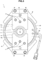
- the exciting coil 15 is fed by power cables 15a derived from a rear end face 13a (see Fig. 3 ) of the field core 13.
- the field core 13 is inserted in the annular groove 8 of the rotor 3. That is, the field core 13 is arranged at a position on the rear side of the rotor 3 (on one side in the axial direction), where a magnetic flux ⁇ of the exciting coil 15 passes through the rotor 3.
- a pair of locking members 16 for preventing the field core 13 from rotating together with the input shaft 2 are fixed to the rear end of the field core 13 by rivets 17.
- Each of the locking members 16 is formed by bending a rectangular metal plate material into a predetermined shape by press work. That is, as shown in Figs. 1 and 3 , the locking members 16 include flat portions 16a extending in the radial direction of the field core 13 along the rear end face 13a of the field core 13, and two arm portions 16b (see Fig. 1 ) extending from the ends of the flat portions 16a in parallel to the axial direction of the input shaft 2.
- a hole 19 used to insert a connecting member 18 that connects the locking member 16 and a fixed housing (not shown) is formed at each of the ends of the flat portions 16a.
- the two arm portions 16b are located outside in the radial direction of the rotor 3 and project from the rotor 3 to the front side of the electromagnetic clutch 1.
- the distal end portion of each arm portion 16b is bent outward in the radial direction of the rotor 3 to form a mounting plate 20.
- Braking plates 21 are attached to the mounting plates 20 by mounting bolts 22, respectively. Rotation of the braking plates 21 is also regulated like the field core 13.
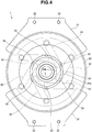
- the braking plates 21 are used to break an armature 23 inserted between the rotor 3 and the braking plates 21 by a frictional resistance generated upon contact with the armature 23 (to be described later). As shown in Figs. 3 and 4 , each the braking plate 21 is formed into a shape that extends from the locking member 16 in the circumferential direction of the rotor 3.
- the braking plates 21 are arranged on the front side of the rotor 3 (the other side in the axial direction), and an interval capable of inserting the armature 23 (to be described later) is formed between the rotor 3 and the braking plates 21, as shown in Fig. 1 .
- the braking plate 21 corresponds to a "braking member" of the present invention.
- a second bearing 24 is provided at the front end of the bearing collar 5 welded to the front end of the boss portion 4 of the rotor 3.
- the second bearing 24 is provided on the front side of the rotor 3 (the other side in the axial direction) on the input shaft portion 6.
- the second bearing 24 corresponds to a "bearing" of the present invention.
- a cylindrical portion 26 of a pulley 25 (to be described later) is fitted on an outer ring 24a of the second bearing 24. That is, the pulley 25 is rotatably supported by the input shaft portion 6 via the second bearing 24.
- An inner ring 24b of the second bearing 24 is pressed backward from the front side by a press plate 27.
- the press plate 27 is pressed against the inner ring 24b by a fixing bolt 28 screwed into the input shaft 2.
- the pulley 25 is a so-called steel pulley, and includes the above-described cylindrical portion 26, a pulley body 31 radially extending outward from the front end of the cylindrical portion 26, and an inner flange 32 connected to the rear end (one end in the axial direction) of the cylindrical portion 26, as shown in Figs. 1 , 2 , and 5 .
- the pulley 25 forms a "rotation transmission member" of the present invention.
- a V belt (not shown) is looped over the pulley body 31.
- a caulking piece 33 is formed at the front end of the cylindrical portion 26 to prevent the pulley 25 from moving backward with respect to the second bearing 24.
- the caulking piece 33 is formed by making part of the inner surface of the cylindrical portion 26 radially project inward by press work, and pressed against the front end face of the outer ring 24a from the front side.
- the inner flange 32 has two functions.
- the first function is the function of regulating forward movement of the pulley 25 with respect to the second bearing 24.
- the inner flange 32 is provided with a plurality of abutment portions 34.
- the abutment portions 34 are arranged at intervals in the rotation direction of the pulley 25.
- the abutment portions 34 are provided at positions to equally divide the pulley 25 into three parts in the rotation direction.
- the abutment portions 34 are formed by making part of the outer edge of the inner flange 32 and part of the cylindrical portion 26 partially plastically deform frontward by press. That is, the abutment portions 34 according to this embodiment are formed by plastically deformed portions 35 provided on the inner flange 32.
- the abutment portions 34 abut against the outer ring 24a of the second bearing 24 from behind (from the side of the rotor 3). That is, the inner flange 32 forms a movement regulating portion 36 that abuts against the second bearing 24 from the side of the rotor 3 in the axial direction and regulates forward movement of the pulley 25.
- the abutment portions 34 are formed on the outer periphery of the inner flange 32, thereby forming a plurality of concave portions 37 (see Figs. 1 , 2 , and 6 ).
- Regions that are not used to implement the first function are formed between the abutment portions 34 of the inner flange 32. These regions are called “non-effective portions 38". That is, the inner flange 32 includes a plurality of non-effective portions 38 located between the abutment portions 34 adjacent to each other in the rotation direction of the pulley 25. A through hole 39 is formed in each of the plurality of non-effective portions 38. In this embodiment, the through hole 39 corresponds to a "third hole" of the present invention.
- the second function of the inner flange 32 is the function of supporting the armature 23 (to be described later).
- a connecting member 41 overlaid on the rear end face (the surface on the other side in the axial direction) of the inner flange 32 and a plurality of first leaf springs 42 and second leaf springs 43 radially extending outward from the connecting member 41 are used.
- the armature 23 is formed into an annular shape with a through hole 23a at the center.
- the armature 23 is arranged between the disc portion 7 of the rotor 3 and the braking plates 21 in a state in which the input shaft portion 6 is inserted in the through hole 23a, and supported by the first leaf springs 42 and the second leaf springs 43 so as to be movable in the axial direction.
- the first leaf springs 42 and the second leaf springs 43 support the armature 23 biased toward the braking plates 21.
- the first leaf springs 42 and the second leaf springs 43 according to this embodiment have the same shape.
- Each leaf spring is formed into a thin strip shape.
- the first leaf spring 42 forms a "first spring member" of the present invention
- the second leaf spring 43 forms a "second spring member" of the present invention.
- first rivet 45 and the second rivet 46 correspond to a "first fixing member” and a "second fixing member” of the present invention, respectively.
- the fixing member not only a rivet but also a bolt, a nut, or a screw can be used.
- the armature 23 can move in the axial direction by a distance corresponding to an air gap G between the disc portion 7 and the braking plates 21 when the first leaf springs 42 and the second leaf springs 43 bend.
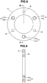
- the connecting member 41 is formed into an annular plate shape.
- a plurality of first rivet insertion holes 47 and a plurality of second rivet insertion holes 48 are formed in the connecting member 41.
- the first rivet insertion holes 47 are each formed from a large-diameter hole 47a and a small-diameter hole 47b, as shown in Fig. 9 , and provided at positions to equally divide the connecting member 41 into three parts in the circumferential direction, as shown in Fig. 8 . More specifically, the first rivet insertion holes 47 are provided at positions facing the plurality of abutment portions 34 of the inner flange 32, as shown in Fig. 2 . In this embodiment, the first rivet insertion hole 47 corresponds to a "first hole" of the present invention.
- the first rivets 45 are inserted into the first rivet insertion holes 47.
- the first rivets 45 extend through the connecting member 41 and the other-end portions 42b of the first leaf springs 42, and fix the other-end portions 42b of the first leaf springs 42 to the rear surface of the connecting member 41. That is, the other-end portions 42b of the first leaf springs 42 are attached to the connecting member 41 by the first rivets 45 inserted into the first rivet insertion holes 47 and fixed to the inner flange 32 via the connecting member 41.
- Proximal-side large-diameter portions 45a (front ends) of the first rivets 45 are stored in the large-diameter holes 47a of the first rivet insertion holes 47, and face the above-described concave portions 37 of the inner flange 32.
- the second rivet insertion holes 48 are each formed from a through hole having a predetermined diameter, as shown in Fig. 9 , and provided between the first rivet insertion holes 47 adjacent to each other at positions to equally divide the connecting member 41 into three parts in the circumferential direction, as shown in Fig. 8 .
- the second rivet insertion holes 48 are provided at positions (portions facing the non-effective portions 38 of the inner flange 32) facing the through holes 39 of the above-described inner flange 32, as shown in Fig. 2 .
- the second rivet insertion hole 48 corresponds to a "second hole" of the present invention.
- the second rivets 46 are inserted into the second rivet insertion holes 48 and the through holes 39 of the inner flange 32.
- the second rivets 46 extend through the inner flange 32, the connecting member 41, and the other-end portions 43b of the second leaf springs 43, and fix the other-end portions 43b of the second leaf springs 43 and the connecting member 41 to the inner flange 32.
- the second rivets 46 fix the connecting member 41 to the rear surface of the inner flange 32, and also fix the other-end portions 43b of the second leaf springs 43 to the rear surface of the connecting member 41.
- the other-end portions 43b of the second leaf springs 43 are fixed to the non-effective portions 38 of the inner flange 32 by a fixing structure 49 including the second rivets 46 inserted into the second rivet insertion holes 48.
- the fixing structure 49 according to this embodiment is formed from the second rivets 46 and the connecting member 41.
- the first leaf springs 42 and the second leaf springs 43 are provided between the armature 23 and the connecting member 41 in a state in which they tilt with respect to the radial direction of the pulley 25 viewed from the front side, as shown in Fig. 4 .
- the first leaf springs 42 are arranged at positions to equally divide the pulley 25 into three parts in the rotation direction.
- the second leaf springs 43 are located between pairs of first leaf springs 42 adjacent to each other.
- the exciting coil 15 when the exciting coil 15 is excited, the armature 23 is magnetically attracted by the rotor 3 and rotates integrally with the rotor 3. The rotation of the armature 23 is transmitted to the pulley 25 via the first leaf springs 42, the second leaf springs 43, and the connecting member 41. For this reason, power is transmitted from the input shaft 2 to the pulley 25 via the electromagnetic clutch 1.
- the armature 23 When the exciting coil 15 changes to a non-excitation state, the armature 23 is separated from the rotor 3 by the spring force of the first leaf springs 42 and the second leaf springs 43 and pressed against the braking plates 21. When the armature 23 is pressed against the braking plates 21 in this way, a braking force is generated, and the pulley 25 that is inertially rotating is stopped and held in the stop state.
- the magnitudes of the braking force and the force to hold the pulley 25 in the stop state depend on the magnitude of the spring force of the first leaf springs 42 and the second leaf springs 43.
- the other-end portions 42b of the first leaf springs 42 are fixed to the connecting member 41 at positions corresponding to the abutment portions 34 provided on the inner flange 32 of the pulley 25. For this reason, when fixing the other-end portions 42b and 43b of the first leaf springs 42 and the second leaf springs 43 to the inner flange 32, attachable positions are not restricted by the abutment portions 34 of the inner flange 32.
- the electromagnetic clutch 1 having the above-described arrangement, the number of spring members that bias the armature 23 against the braking plates 21 increases by the number of first leaf springs 42, as compared to, for example, the electromagnetic clutch described in the literature. Hence, according to this embodiment, since the number of spring members that bias the armature 23 can be increased, the braking force and the holding force to hold the standstill state can be increased.
- the pulley 25 includes the cylindrical portion 26 in which the second bearing 24 is fitted, and the inner flange 32 radially extending inward from the cylindrical portion 26 and forming the movement regulating portion 36.
- the abutment portions 34 are formed from the plastically deformed portions 35 that are formed by making part of the inner flange 32 project toward the second bearing 24.
- the proximal-side large-diameter portions 45a as one-end portions of the first rivets 45 face the concave portions 37 made by forming the abutment portions 34 on the inner flange 32. It is therefore possible to form the pulley 25 using the steel pulley 25 and reduce the weight of the pulley 25. Hence, the time until the pulley 25 stops can be shortened without changing the spring force of the first leaf springs 42 and the second leaf springs 43 and the arrangement of the braking plates 21.
- the other-end portions 43b of the second leaf springs 43 are fixed to the inner flange 32 via the connecting member 41. It is therefore possible to form the first leaf springs 42 and the second leaf springs 43 into the same shape and reduce the cost.
Landscapes
- Engineering & Computer Science (AREA)
- General Engineering & Computer Science (AREA)
- Mechanical Engineering (AREA)
- Physics & Mathematics (AREA)
- Electromagnetism (AREA)
- Braking Arrangements (AREA)
Claims (4)
- Embrayage électromagnétique (1) comprenant :une portion d'arbre d'entrée (6) qui tourne lors de la réception d'une puissance émise ;un rotor (3) qui s'étend radialement vers l'extérieur à partir de la portion d'arbre d'entrée (6) et tourne en un seul tenant avec la portion d'arbre d'entrée (6) ;un noyau inducteur (13) qui inclut une bobine d'excitation (15) et est prévu à une position où un flux magnétique de la bobine d'excitation (15) passe à travers le rotor (3) sur un côté du rotor (3) dans une direction axiale dans un état dans lequel la rotation est régulée ;un élément de freinage (21) disposé sur l'autre côté du rotor (3) dans la direction axiale dans l'état dans lequel la rotation est régulée ;un palier (24) prévu sur l'autre côté du rotor (3) dans la direction axiale sur la portion d'arbre d'entrée (6) ;un élément de transmission de rotation (25) qui inclut une portion de régulation de mouvement (36) qui bute contre le palier (24) à partir d'un côté du rotor (3) et régule le mouvement de l'élément de transmission de rotation (25) sur un côté dans la direction axiale et est soutenue rotativement par la portion d'arbre d'entrée (6) via le palier (24), la portion de régulation de mouvement (36) incluant une pluralité de portions de butée (34) qui sont formées à des intervalles dans une direction de rotation de l'élément de transmission de rotation (25) et butent contre le palier (24) ;un élément de raccordement (41) qui est superposé sur une surface de la portion de régulation de mouvement (36) dans la direction axiale, l'élément de raccordement (41) incluant une pluralité de premiers trous (47) respectivement prévus au niveau de portions faisant face à la pluralité de portions de butée (34) et une pluralité de seconds trous (48) prévus au niveau de portions faisant face à des régions (38) entre la pluralité de portions de butée (34) ;une armature (23) qui est formée dans une forme annulaire avec un trou traversant (23a) au niveau d'un centre et disposée entre le rotor (3) et l'élément de freinage (21) dans un état dans lequel la portion d'arbre d'entrée (6) est insérée dans le trou traversant (23a) et est déplaçable dans la direction axiale par une distance correspondant à un entrefer ;une pluralité de premiers éléments de ressort (42) et une pluralité de seconds éléments de ressort (43) qui incluent des portions terminales (42a, 43a) fixées à l'armature (23) et d'autres portions terminales (42b, 43b) et soutiennent l'armature (23) tout en sollicitant l'armature (23) dans la direction de l'élément de freinage (21) ;une pluralité de premiers éléments de fixation (45) qui sont insérés dans la pluralité de premiers trous (47) de l'élément de raccordement (41), respectivement, et fixent les autres portions terminales (42b) de la pluralité de premiers éléments de ressort (42) à l'élément de raccordement (41) ; et une pluralité de seconds éléments de fixation (46) qui sont insérés dans la pluralité de seconds trous (48) de l'élément de raccordement (41), respectivement, et fixent les autres portions terminales (43b) de la pluralité de seconds éléments de ressort (43) et l'élément de raccordement (41) aux régions (38) de la portion de régulation de mouvement (36).
- Embrayage électromagnétique (1) selon la revendication 1, dans lequel l'élément de transmission de rotation (25) inclut en outre une portion cylindrique (26) dans laquelle le palier (24) est ajusté,
la portion de régulation de mouvement (36) est formée à partir d'une bride extérieure (32) s'étendant radialement vers l'intérieur à partir de la portion cylindrique (26),
chacune des portions de butée (34) est formée à partir d'une portion déformée plastiquement (35) formée en amenant une partie de la bride intérieure (32) à se projeter vers le palier (24), et
une portion terminale de chacun des premiers éléments de fixation (45) fait face à une portion concave (37) réalisée en formant la portion de butée (34) sur la bride intérieure (32). - Embrayage électromagnétique (1) selon la revendication 1, dans lequel la portion de régulation de mouvement (36) inclut en outre une pluralité de troisièmes trous (39) prévus dans des régions (38), et
la pluralité de seconds éléments de fixation (46) sont insérés dans la pluralité de seconds trous (48) et la pluralité de troisièmes trous (39). - Embrayage électromagnétique (1) selon la revendication 1, dans lequel chacun de la pluralité de premiers éléments de fixation (45) et la pluralité de seconds éléments de fixation (46) est formé d'un rivet.
Applications Claiming Priority (1)
| Application Number | Priority Date | Filing Date | Title |
|---|---|---|---|
| JP2015059467A JP6402057B2 (ja) | 2015-03-23 | 2015-03-23 | 電磁クラッチ |
Publications (3)
| Publication Number | Publication Date |
|---|---|
| EP3073143A2 EP3073143A2 (fr) | 2016-09-28 |
| EP3073143A3 EP3073143A3 (fr) | 2016-10-05 |
| EP3073143B1 true EP3073143B1 (fr) | 2017-09-13 |
Family
ID=55542480
Family Applications (1)
| Application Number | Title | Priority Date | Filing Date |
|---|---|---|---|
| EP16160566.2A Not-in-force EP3073143B1 (fr) | 2015-03-23 | 2016-03-16 | Embrayage électromagnétique |
Country Status (4)
| Country | Link |
|---|---|
| US (1) | US9631688B2 (fr) |
| EP (1) | EP3073143B1 (fr) |
| JP (1) | JP6402057B2 (fr) |
| CN (1) | CN105987095B (fr) |
Families Citing this family (4)
| Publication number | Priority date | Publication date | Assignee | Title |
|---|---|---|---|---|
| JP6857967B2 (ja) * | 2016-04-05 | 2021-04-14 | 小倉クラッチ株式会社 | 電磁石用リード線のシール構造 |
| US10995803B2 (en) * | 2018-12-04 | 2021-05-04 | Means Industries, Inc. | Electromagnetic system for controlling the operating mode of a non friction coupling assembly and coupling and magnetic control assembly having same |
| US10883552B2 (en) * | 2019-04-10 | 2021-01-05 | Warner Electric Technology Llc | Rotational coupling device with flux conducting bearing shield |
| US12203519B1 (en) | 2024-03-12 | 2025-01-21 | Warner Electric Technology Llc | Rotational coupling device with bearing shield |
Family Cites Families (9)
| Publication number | Priority date | Publication date | Assignee | Title |
|---|---|---|---|---|
| US3082933A (en) * | 1960-12-16 | 1963-03-26 | Gen Motors Corp | Electromagnetic clutch |
| JPS5947538A (ja) * | 1982-09-10 | 1984-03-17 | Shinko Electric Co Ltd | 電磁クラツチ・ブレ−キ |
| JPS59133840A (ja) * | 1983-01-21 | 1984-08-01 | Ogura Clutch Co Ltd | 電磁クラツチ・ブレ−キ |
| US5119918A (en) * | 1991-10-11 | 1992-06-09 | Dana Corporation | Electromagnetic clutch with permanent magnet brake |
| US5971121A (en) * | 1998-04-30 | 1999-10-26 | Pardee; James Alain | Mag stop clutch with center pole |
| DE10059747A1 (de) * | 2000-12-01 | 2002-06-06 | Hilti Ag | Elektrohandwerkzeug mit Sicherheitskupplung |
| US7732959B2 (en) * | 2005-06-10 | 2010-06-08 | Warner Electric Technology, Llc | Rotational coupling device |
| JP2013234723A (ja) * | 2012-05-10 | 2013-11-21 | Ogura Clutch Co Ltd | 電磁クラッチ |
| DE102012221369A1 (de) * | 2012-11-22 | 2014-05-22 | Schaeffler Technologies Gmbh & Co. Kg | Wälzlager |
-
2015
- 2015-03-23 JP JP2015059467A patent/JP6402057B2/ja active Active
-
2016
- 2016-03-16 EP EP16160566.2A patent/EP3073143B1/fr not_active Not-in-force
- 2016-03-21 US US15/076,262 patent/US9631688B2/en active Active
- 2016-03-23 CN CN201610168110.8A patent/CN105987095B/zh not_active Expired - Fee Related
Non-Patent Citations (1)
| Title |
|---|
| None * |
Also Published As
| Publication number | Publication date |
|---|---|
| JP2016180415A (ja) | 2016-10-13 |
| CN105987095B (zh) | 2018-08-21 |
| CN105987095A (zh) | 2016-10-05 |
| JP6402057B2 (ja) | 2018-10-10 |
| EP3073143A2 (fr) | 2016-09-28 |
| US20160281809A1 (en) | 2016-09-29 |
| EP3073143A3 (fr) | 2016-10-05 |
| US9631688B2 (en) | 2017-04-25 |
Similar Documents
| Publication | Publication Date | Title |
|---|---|---|
| EP3073143B1 (fr) | Embrayage électromagnétique | |
| JP3125160B2 (ja) | 電磁継手用アーマチュア・アセンブリ | |
| EP2952767B1 (fr) | Dispositif de transmission de mouvement de rotation | |
| US20120111690A1 (en) | Electromagnetic clutch | |
| CN105934601A (zh) | 旋转传递装置 | |
| JP2008008460A (ja) | デファレンシャル装置 | |
| EP3141772B1 (fr) | Embrayage électromagnétique | |
| EP3550167B1 (fr) | Dispositif de connexion électromagnétique | |
| US8973727B1 (en) | Electromagnetic clutch | |
| JP6684187B2 (ja) | 電磁クラッチ | |
| US7604105B2 (en) | Rotation transmission device | |
| JP2013234723A (ja) | 電磁クラッチ | |
| JP5509052B2 (ja) | 電磁クラッチ | |
| JP4541178B2 (ja) | 回転伝達装置 | |
| JP2006226366A (ja) | 回転伝達装置 | |
| JP2006226350A (ja) | 回転伝達装置 | |
| JPH0642105Y2 (ja) | 電磁連結装置 | |
| JP2011112060A (ja) | 電磁連結装置 | |
| JP2005054907A (ja) | 無励磁作動型の電磁ブレーキ | |
| JPH0126907Y2 (fr) | ||
| JP2009144867A (ja) | 回転伝達装置 | |
| JP2006233847A (ja) | 圧縮機の電磁クラッチ | |
| JP2007187246A (ja) | 回転伝達装置 | |
| JP2008095734A (ja) | 回転伝達装置 | |
| JPH0734232U (ja) | 電磁連結装置 |
Legal Events
| Date | Code | Title | Description |
|---|---|---|---|
| PUAI | Public reference made under article 153(3) epc to a published international application that has entered the european phase |
Free format text: ORIGINAL CODE: 0009012 |
|
| PUAL | Search report despatched |
Free format text: ORIGINAL CODE: 0009013 |
|
| AK | Designated contracting states |
Kind code of ref document: A2 Designated state(s): AL AT BE BG CH CY CZ DE DK EE ES FI FR GB GR HR HU IE IS IT LI LT LU LV MC MK MT NL NO PL PT RO RS SE SI SK SM TR |
|
| AX | Request for extension of the european patent |
Extension state: BA ME |
|
| AK | Designated contracting states |
Kind code of ref document: A3 Designated state(s): AL AT BE BG CH CY CZ DE DK EE ES FI FR GB GR HR HU IE IS IT LI LT LU LV MC MK MT NL NO PL PT RO RS SE SI SK SM TR |
|
| AX | Request for extension of the european patent |
Extension state: BA ME |
|
| RIC1 | Information provided on ipc code assigned before grant |
Ipc: F16D 67/06 20060101ALI20160830BHEP Ipc: F16D 27/112 20060101AFI20160830BHEP Ipc: F16D 27/00 20060101ALN20160830BHEP |
|
| STAA | Information on the status of an ep patent application or granted ep patent |
Free format text: STATUS: REQUEST FOR EXAMINATION WAS MADE |
|
| 17P | Request for examination filed |
Effective date: 20161130 |
|
| RBV | Designated contracting states (corrected) |
Designated state(s): AL AT BE BG CH CY CZ DE DK EE ES FI FR GB GR HR HU IE IS IT LI LT LU LV MC MK MT NL NO PL PT RO RS SE SI SK SM TR |
|
| GRAP | Despatch of communication of intention to grant a patent |
Free format text: ORIGINAL CODE: EPIDOSNIGR1 |
|
| STAA | Information on the status of an ep patent application or granted ep patent |
Free format text: STATUS: GRANT OF PATENT IS INTENDED |
|
| RIC1 | Information provided on ipc code assigned before grant |
Ipc: F16D 27/00 20060101ALN20170317BHEP Ipc: F16D 67/06 20060101ALI20170317BHEP Ipc: F16D 27/112 20060101AFI20170317BHEP |
|
| INTG | Intention to grant announced |
Effective date: 20170405 |
|
| GRAS | Grant fee paid |
Free format text: ORIGINAL CODE: EPIDOSNIGR3 |
|
| GRAA | (expected) grant |
Free format text: ORIGINAL CODE: 0009210 |
|
| STAA | Information on the status of an ep patent application or granted ep patent |
Free format text: STATUS: THE PATENT HAS BEEN GRANTED |
|
| AK | Designated contracting states |
Kind code of ref document: B1 Designated state(s): AL AT BE BG CH CY CZ DE DK EE ES FI FR GB GR HR HU IE IS IT LI LT LU LV MC MK MT NL NO PL PT RO RS SE SI SK SM TR |
|
| REG | Reference to a national code |
Ref country code: GB Ref legal event code: FG4D |
|
| REG | Reference to a national code |
Ref country code: CH Ref legal event code: EP |
|
| REG | Reference to a national code |
Ref country code: IE Ref legal event code: FG4D |
|
| REG | Reference to a national code |
Ref country code: AT Ref legal event code: REF Ref document number: 928464 Country of ref document: AT Kind code of ref document: T Effective date: 20171015 |
|
| REG | Reference to a national code |
Ref country code: DE Ref legal event code: R096 Ref document number: 602016000368 Country of ref document: DE |
|
| REG | Reference to a national code |
Ref country code: NL Ref legal event code: MP Effective date: 20170913 |
|
| REG | Reference to a national code |
Ref country code: LT Ref legal event code: MG4D |
|
| PG25 | Lapsed in a contracting state [announced via postgrant information from national office to epo] |
Ref country code: SE Free format text: LAPSE BECAUSE OF FAILURE TO SUBMIT A TRANSLATION OF THE DESCRIPTION OR TO PAY THE FEE WITHIN THE PRESCRIBED TIME-LIMIT Effective date: 20170913 Ref country code: FI Free format text: LAPSE BECAUSE OF FAILURE TO SUBMIT A TRANSLATION OF THE DESCRIPTION OR TO PAY THE FEE WITHIN THE PRESCRIBED TIME-LIMIT Effective date: 20170913 Ref country code: NO Free format text: LAPSE BECAUSE OF FAILURE TO SUBMIT A TRANSLATION OF THE DESCRIPTION OR TO PAY THE FEE WITHIN THE PRESCRIBED TIME-LIMIT Effective date: 20171213 Ref country code: HR Free format text: LAPSE BECAUSE OF FAILURE TO SUBMIT A TRANSLATION OF THE DESCRIPTION OR TO PAY THE FEE WITHIN THE PRESCRIBED TIME-LIMIT Effective date: 20170913 Ref country code: LT Free format text: LAPSE BECAUSE OF FAILURE TO SUBMIT A TRANSLATION OF THE DESCRIPTION OR TO PAY THE FEE WITHIN THE PRESCRIBED TIME-LIMIT Effective date: 20170913 |
|
| REG | Reference to a national code |
Ref country code: AT Ref legal event code: MK05 Ref document number: 928464 Country of ref document: AT Kind code of ref document: T Effective date: 20170913 |
|
| PG25 | Lapsed in a contracting state [announced via postgrant information from national office to epo] |
Ref country code: RS Free format text: LAPSE BECAUSE OF FAILURE TO SUBMIT A TRANSLATION OF THE DESCRIPTION OR TO PAY THE FEE WITHIN THE PRESCRIBED TIME-LIMIT Effective date: 20170913 Ref country code: GR Free format text: LAPSE BECAUSE OF FAILURE TO SUBMIT A TRANSLATION OF THE DESCRIPTION OR TO PAY THE FEE WITHIN THE PRESCRIBED TIME-LIMIT Effective date: 20171214 Ref country code: BG Free format text: LAPSE BECAUSE OF FAILURE TO SUBMIT A TRANSLATION OF THE DESCRIPTION OR TO PAY THE FEE WITHIN THE PRESCRIBED TIME-LIMIT Effective date: 20171213 Ref country code: LV Free format text: LAPSE BECAUSE OF FAILURE TO SUBMIT A TRANSLATION OF THE DESCRIPTION OR TO PAY THE FEE WITHIN THE PRESCRIBED TIME-LIMIT Effective date: 20170913 Ref country code: ES Free format text: LAPSE BECAUSE OF FAILURE TO SUBMIT A TRANSLATION OF THE DESCRIPTION OR TO PAY THE FEE WITHIN THE PRESCRIBED TIME-LIMIT Effective date: 20170913 |
|
| PG25 | Lapsed in a contracting state [announced via postgrant information from national office to epo] |
Ref country code: NL Free format text: LAPSE BECAUSE OF FAILURE TO SUBMIT A TRANSLATION OF THE DESCRIPTION OR TO PAY THE FEE WITHIN THE PRESCRIBED TIME-LIMIT Effective date: 20170913 |
|
| PG25 | Lapsed in a contracting state [announced via postgrant information from national office to epo] |
Ref country code: CZ Free format text: LAPSE BECAUSE OF FAILURE TO SUBMIT A TRANSLATION OF THE DESCRIPTION OR TO PAY THE FEE WITHIN THE PRESCRIBED TIME-LIMIT Effective date: 20170913 Ref country code: RO Free format text: LAPSE BECAUSE OF FAILURE TO SUBMIT A TRANSLATION OF THE DESCRIPTION OR TO PAY THE FEE WITHIN THE PRESCRIBED TIME-LIMIT Effective date: 20170913 Ref country code: PL Free format text: LAPSE BECAUSE OF FAILURE TO SUBMIT A TRANSLATION OF THE DESCRIPTION OR TO PAY THE FEE WITHIN THE PRESCRIBED TIME-LIMIT Effective date: 20170913 |
|
| PG25 | Lapsed in a contracting state [announced via postgrant information from national office to epo] |
Ref country code: SK Free format text: LAPSE BECAUSE OF FAILURE TO SUBMIT A TRANSLATION OF THE DESCRIPTION OR TO PAY THE FEE WITHIN THE PRESCRIBED TIME-LIMIT Effective date: 20170913 Ref country code: SM Free format text: LAPSE BECAUSE OF FAILURE TO SUBMIT A TRANSLATION OF THE DESCRIPTION OR TO PAY THE FEE WITHIN THE PRESCRIBED TIME-LIMIT Effective date: 20170913 Ref country code: IS Free format text: LAPSE BECAUSE OF FAILURE TO SUBMIT A TRANSLATION OF THE DESCRIPTION OR TO PAY THE FEE WITHIN THE PRESCRIBED TIME-LIMIT Effective date: 20180113 Ref country code: AT Free format text: LAPSE BECAUSE OF FAILURE TO SUBMIT A TRANSLATION OF THE DESCRIPTION OR TO PAY THE FEE WITHIN THE PRESCRIBED TIME-LIMIT Effective date: 20170913 Ref country code: EE Free format text: LAPSE BECAUSE OF FAILURE TO SUBMIT A TRANSLATION OF THE DESCRIPTION OR TO PAY THE FEE WITHIN THE PRESCRIBED TIME-LIMIT Effective date: 20170913 |
|
| REG | Reference to a national code |
Ref country code: DE Ref legal event code: R097 Ref document number: 602016000368 Country of ref document: DE |
|
| PLBE | No opposition filed within time limit |
Free format text: ORIGINAL CODE: 0009261 |
|
| STAA | Information on the status of an ep patent application or granted ep patent |
Free format text: STATUS: NO OPPOSITION FILED WITHIN TIME LIMIT |
|
| PG25 | Lapsed in a contracting state [announced via postgrant information from national office to epo] |
Ref country code: DK Free format text: LAPSE BECAUSE OF FAILURE TO SUBMIT A TRANSLATION OF THE DESCRIPTION OR TO PAY THE FEE WITHIN THE PRESCRIBED TIME-LIMIT Effective date: 20170913 |
|
| 26N | No opposition filed |
Effective date: 20180614 |
|
| PG25 | Lapsed in a contracting state [announced via postgrant information from national office to epo] |
Ref country code: MC Free format text: LAPSE BECAUSE OF FAILURE TO SUBMIT A TRANSLATION OF THE DESCRIPTION OR TO PAY THE FEE WITHIN THE PRESCRIBED TIME-LIMIT Effective date: 20170913 Ref country code: SI Free format text: LAPSE BECAUSE OF FAILURE TO SUBMIT A TRANSLATION OF THE DESCRIPTION OR TO PAY THE FEE WITHIN THE PRESCRIBED TIME-LIMIT Effective date: 20170913 |
|
| REG | Reference to a national code |
Ref country code: BE Ref legal event code: MM Effective date: 20180331 |
|
| REG | Reference to a national code |
Ref country code: IE Ref legal event code: MM4A |
|
| PG25 | Lapsed in a contracting state [announced via postgrant information from national office to epo] |
Ref country code: LU Free format text: LAPSE BECAUSE OF NON-PAYMENT OF DUE FEES Effective date: 20180316 |
|
| PG25 | Lapsed in a contracting state [announced via postgrant information from national office to epo] |
Ref country code: IE Free format text: LAPSE BECAUSE OF NON-PAYMENT OF DUE FEES Effective date: 20180316 |
|
| PG25 | Lapsed in a contracting state [announced via postgrant information from national office to epo] |
Ref country code: BE Free format text: LAPSE BECAUSE OF NON-PAYMENT OF DUE FEES Effective date: 20180331 |
|
| PG25 | Lapsed in a contracting state [announced via postgrant information from national office to epo] |
Ref country code: FR Free format text: LAPSE BECAUSE OF NON-PAYMENT OF DUE FEES Effective date: 20180331 |
|
| PGFP | Annual fee paid to national office [announced via postgrant information from national office to epo] |
Ref country code: IT Payment date: 20190331 Year of fee payment: 4 Ref country code: DE Payment date: 20190331 Year of fee payment: 4 |
|
| REG | Reference to a national code |
Ref country code: CH Ref legal event code: PL |
|
| PG25 | Lapsed in a contracting state [announced via postgrant information from national office to epo] |
Ref country code: CH Free format text: LAPSE BECAUSE OF NON-PAYMENT OF DUE FEES Effective date: 20190331 Ref country code: LI Free format text: LAPSE BECAUSE OF NON-PAYMENT OF DUE FEES Effective date: 20190331 Ref country code: MT Free format text: LAPSE BECAUSE OF NON-PAYMENT OF DUE FEES Effective date: 20180316 |
|
| PG25 | Lapsed in a contracting state [announced via postgrant information from national office to epo] |
Ref country code: TR Free format text: LAPSE BECAUSE OF FAILURE TO SUBMIT A TRANSLATION OF THE DESCRIPTION OR TO PAY THE FEE WITHIN THE PRESCRIBED TIME-LIMIT Effective date: 20170913 |
|
| PG25 | Lapsed in a contracting state [announced via postgrant information from national office to epo] |
Ref country code: PT Free format text: LAPSE BECAUSE OF FAILURE TO SUBMIT A TRANSLATION OF THE DESCRIPTION OR TO PAY THE FEE WITHIN THE PRESCRIBED TIME-LIMIT Effective date: 20170913 |
|
| PG25 | Lapsed in a contracting state [announced via postgrant information from national office to epo] |
Ref country code: HU Free format text: LAPSE BECAUSE OF FAILURE TO SUBMIT A TRANSLATION OF THE DESCRIPTION OR TO PAY THE FEE WITHIN THE PRESCRIBED TIME-LIMIT; INVALID AB INITIO Effective date: 20160316 Ref country code: MK Free format text: LAPSE BECAUSE OF NON-PAYMENT OF DUE FEES Effective date: 20170913 Ref country code: CY Free format text: LAPSE BECAUSE OF FAILURE TO SUBMIT A TRANSLATION OF THE DESCRIPTION OR TO PAY THE FEE WITHIN THE PRESCRIBED TIME-LIMIT Effective date: 20170913 |
|
| PG25 | Lapsed in a contracting state [announced via postgrant information from national office to epo] |
Ref country code: AL Free format text: LAPSE BECAUSE OF FAILURE TO SUBMIT A TRANSLATION OF THE DESCRIPTION OR TO PAY THE FEE WITHIN THE PRESCRIBED TIME-LIMIT Effective date: 20170913 |
|
| REG | Reference to a national code |
Ref country code: DE Ref legal event code: R119 Ref document number: 602016000368 Country of ref document: DE |
|
| PG25 | Lapsed in a contracting state [announced via postgrant information from national office to epo] |
Ref country code: DE Free format text: LAPSE BECAUSE OF NON-PAYMENT OF DUE FEES Effective date: 20201001 |
|
| GBPC | Gb: european patent ceased through non-payment of renewal fee |
Effective date: 20200316 |
|
| PG25 | Lapsed in a contracting state [announced via postgrant information from national office to epo] |
Ref country code: GB Free format text: LAPSE BECAUSE OF NON-PAYMENT OF DUE FEES Effective date: 20200316 |
|
| PG25 | Lapsed in a contracting state [announced via postgrant information from national office to epo] |
Ref country code: IT Free format text: LAPSE BECAUSE OF NON-PAYMENT OF DUE FEES Effective date: 20200316 |