EP3075704B1 - Four pour le reformage a la vapeur d'hydrocarbures dote de tubes chauffables par combustion et electriquement - Google Patents
Four pour le reformage a la vapeur d'hydrocarbures dote de tubes chauffables par combustion et electriquement Download PDFInfo
- Publication number
- EP3075704B1 EP3075704B1 EP16000387.7A EP16000387A EP3075704B1 EP 3075704 B1 EP3075704 B1 EP 3075704B1 EP 16000387 A EP16000387 A EP 16000387A EP 3075704 B1 EP3075704 B1 EP 3075704B1
- Authority
- EP
- European Patent Office
- Prior art keywords
- reactor tubes
- furnace
- reactor
- furnace according
- feed stream
- Prior art date
- Legal status (The legal status is an assumption and is not a legal conclusion. Google has not performed a legal analysis and makes no representation as to the accuracy of the status listed.)
- Active
Links
Images


Classifications
-
- B—PERFORMING OPERATIONS; TRANSPORTING
- B01—PHYSICAL OR CHEMICAL PROCESSES OR APPARATUS IN GENERAL
- B01J—CHEMICAL OR PHYSICAL PROCESSES, e.g. CATALYSIS OR COLLOID CHEMISTRY; THEIR RELEVANT APPARATUS
- B01J8/00—Chemical or physical processes in general, conducted in the presence of fluids and solid particles; Apparatus for such processes
- B01J8/02—Chemical or physical processes in general, conducted in the presence of fluids and solid particles; Apparatus for such processes with stationary particles, e.g. in fixed beds
- B01J8/06—Chemical or physical processes in general, conducted in the presence of fluids and solid particles; Apparatus for such processes with stationary particles, e.g. in fixed beds in tube reactors; the solid particles being arranged in tubes
- B01J8/067—Heating or cooling the reactor
-
- B—PERFORMING OPERATIONS; TRANSPORTING
- B01—PHYSICAL OR CHEMICAL PROCESSES OR APPARATUS IN GENERAL
- B01J—CHEMICAL OR PHYSICAL PROCESSES, e.g. CATALYSIS OR COLLOID CHEMISTRY; THEIR RELEVANT APPARATUS
- B01J19/00—Chemical, physical or physico-chemical processes in general; Their relevant apparatus
- B01J19/08—Processes employing the direct application of electric or wave energy, or particle radiation; Apparatus therefor
-
- B—PERFORMING OPERATIONS; TRANSPORTING
- B01—PHYSICAL OR CHEMICAL PROCESSES OR APPARATUS IN GENERAL
- B01J—CHEMICAL OR PHYSICAL PROCESSES, e.g. CATALYSIS OR COLLOID CHEMISTRY; THEIR RELEVANT APPARATUS
- B01J8/00—Chemical or physical processes in general, conducted in the presence of fluids and solid particles; Apparatus for such processes
- B01J8/02—Chemical or physical processes in general, conducted in the presence of fluids and solid particles; Apparatus for such processes with stationary particles, e.g. in fixed beds
- B01J8/06—Chemical or physical processes in general, conducted in the presence of fluids and solid particles; Apparatus for such processes with stationary particles, e.g. in fixed beds in tube reactors; the solid particles being arranged in tubes
-
- B—PERFORMING OPERATIONS; TRANSPORTING
- B01—PHYSICAL OR CHEMICAL PROCESSES OR APPARATUS IN GENERAL
- B01J—CHEMICAL OR PHYSICAL PROCESSES, e.g. CATALYSIS OR COLLOID CHEMISTRY; THEIR RELEVANT APPARATUS
- B01J8/00—Chemical or physical processes in general, conducted in the presence of fluids and solid particles; Apparatus for such processes
- B01J8/02—Chemical or physical processes in general, conducted in the presence of fluids and solid particles; Apparatus for such processes with stationary particles, e.g. in fixed beds
- B01J8/06—Chemical or physical processes in general, conducted in the presence of fluids and solid particles; Apparatus for such processes with stationary particles, e.g. in fixed beds in tube reactors; the solid particles being arranged in tubes
- B01J8/062—Chemical or physical processes in general, conducted in the presence of fluids and solid particles; Apparatus for such processes with stationary particles, e.g. in fixed beds in tube reactors; the solid particles being arranged in tubes being installed in a furnace
-
- C—CHEMISTRY; METALLURGY
- C01—INORGANIC CHEMISTRY
- C01B—NON-METALLIC ELEMENTS; COMPOUNDS THEREOF; METALLOIDS OR COMPOUNDS THEREOF NOT COVERED BY SUBCLASS C01C
- C01B3/00—Hydrogen; Gaseous mixtures containing hydrogen; Separation of hydrogen from mixtures containing it; Purification of hydrogen; Reversible storage of hydrogen
- C01B3/02—Production of hydrogen; Production of gaseous mixtures containing hydrogen
- C01B3/32—Production of hydrogen; Production of gaseous mixtures containing hydrogen by reaction of gaseous or liquid organic compounds with gasifying agents, e.g. water, carbon dioxide or air
- C01B3/34—Production of hydrogen; Production of gaseous mixtures containing hydrogen by reaction of gaseous or liquid organic compounds with gasifying agents, e.g. water, carbon dioxide or air by reaction of hydrocarbons with gasifying agents
- C01B3/38—Production of hydrogen; Production of gaseous mixtures containing hydrogen by reaction of gaseous or liquid organic compounds with gasifying agents, e.g. water, carbon dioxide or air by reaction of hydrocarbons with gasifying agents using catalysts
-
- C—CHEMISTRY; METALLURGY
- C01—INORGANIC CHEMISTRY
- C01B—NON-METALLIC ELEMENTS; COMPOUNDS THEREOF; METALLOIDS OR COMPOUNDS THEREOF NOT COVERED BY SUBCLASS C01C
- C01B3/00—Hydrogen; Gaseous mixtures containing hydrogen; Separation of hydrogen from mixtures containing it; Purification of hydrogen; Reversible storage of hydrogen
- C01B3/02—Production of hydrogen; Production of gaseous mixtures containing hydrogen
- C01B3/32—Production of hydrogen; Production of gaseous mixtures containing hydrogen by reaction of gaseous or liquid organic compounds with gasifying agents, e.g. water, carbon dioxide or air
- C01B3/34—Production of hydrogen; Production of gaseous mixtures containing hydrogen by reaction of gaseous or liquid organic compounds with gasifying agents, e.g. water, carbon dioxide or air by reaction of hydrocarbons with gasifying agents
- C01B3/38—Production of hydrogen; Production of gaseous mixtures containing hydrogen by reaction of gaseous or liquid organic compounds with gasifying agents, e.g. water, carbon dioxide or air by reaction of hydrocarbons with gasifying agents using catalysts
- C01B3/384—Production of hydrogen; Production of gaseous mixtures containing hydrogen by reaction of gaseous or liquid organic compounds with gasifying agents, e.g. water, carbon dioxide or air by reaction of hydrocarbons with gasifying agents using catalysts with external heating of the catalyst
-
- B—PERFORMING OPERATIONS; TRANSPORTING
- B01—PHYSICAL OR CHEMICAL PROCESSES OR APPARATUS IN GENERAL
- B01J—CHEMICAL OR PHYSICAL PROCESSES, e.g. CATALYSIS OR COLLOID CHEMISTRY; THEIR RELEVANT APPARATUS
- B01J2208/00—Processes carried out in the presence of solid particles; Reactors therefor
- B01J2208/00008—Controlling the process
- B01J2208/00017—Controlling the temperature
- B01J2208/00106—Controlling the temperature by indirect heat exchange
- B01J2208/00168—Controlling the temperature by indirect heat exchange with heat exchange elements outside the bed of solid particles
-
- B—PERFORMING OPERATIONS; TRANSPORTING
- B01—PHYSICAL OR CHEMICAL PROCESSES OR APPARATUS IN GENERAL
- B01J—CHEMICAL OR PHYSICAL PROCESSES, e.g. CATALYSIS OR COLLOID CHEMISTRY; THEIR RELEVANT APPARATUS
- B01J2208/00—Processes carried out in the presence of solid particles; Reactors therefor
- B01J2208/00008—Controlling the process
- B01J2208/00017—Controlling the temperature
- B01J2208/00389—Controlling the temperature using electric heating or cooling elements
- B01J2208/00407—Controlling the temperature using electric heating or cooling elements outside the reactor bed
-
- B—PERFORMING OPERATIONS; TRANSPORTING
- B01—PHYSICAL OR CHEMICAL PROCESSES OR APPARATUS IN GENERAL
- B01J—CHEMICAL OR PHYSICAL PROCESSES, e.g. CATALYSIS OR COLLOID CHEMISTRY; THEIR RELEVANT APPARATUS
- B01J2208/00—Processes carried out in the presence of solid particles; Reactors therefor
- B01J2208/00008—Controlling the process
- B01J2208/00017—Controlling the temperature
- B01J2208/00389—Controlling the temperature using electric heating or cooling elements
- B01J2208/00415—Controlling the temperature using electric heating or cooling elements electric resistance heaters
-
- B—PERFORMING OPERATIONS; TRANSPORTING
- B01—PHYSICAL OR CHEMICAL PROCESSES OR APPARATUS IN GENERAL
- B01J—CHEMICAL OR PHYSICAL PROCESSES, e.g. CATALYSIS OR COLLOID CHEMISTRY; THEIR RELEVANT APPARATUS
- B01J2208/00—Processes carried out in the presence of solid particles; Reactors therefor
- B01J2208/00008—Controlling the process
- B01J2208/00017—Controlling the temperature
- B01J2208/00504—Controlling the temperature by means of a burner
-
- B—PERFORMING OPERATIONS; TRANSPORTING
- B01—PHYSICAL OR CHEMICAL PROCESSES OR APPARATUS IN GENERAL
- B01J—CHEMICAL OR PHYSICAL PROCESSES, e.g. CATALYSIS OR COLLOID CHEMISTRY; THEIR RELEVANT APPARATUS
- B01J2208/00—Processes carried out in the presence of solid particles; Reactors therefor
- B01J2208/06—Details of tube reactors containing solid particles
- B01J2208/065—Heating or cooling the reactor
-
- C—CHEMISTRY; METALLURGY
- C01—INORGANIC CHEMISTRY
- C01B—NON-METALLIC ELEMENTS; COMPOUNDS THEREOF; METALLOIDS OR COMPOUNDS THEREOF NOT COVERED BY SUBCLASS C01C
- C01B2203/00—Integrated processes for the production of hydrogen or synthesis gas
- C01B2203/02—Processes for making hydrogen or synthesis gas
- C01B2203/0205—Processes for making hydrogen or synthesis gas containing a reforming step
- C01B2203/0227—Processes for making hydrogen or synthesis gas containing a reforming step containing a catalytic reforming step
- C01B2203/0233—Processes for making hydrogen or synthesis gas containing a reforming step containing a catalytic reforming step the reforming step being a steam reforming step
-
- C—CHEMISTRY; METALLURGY
- C01—INORGANIC CHEMISTRY
- C01B—NON-METALLIC ELEMENTS; COMPOUNDS THEREOF; METALLOIDS OR COMPOUNDS THEREOF NOT COVERED BY SUBCLASS C01C
- C01B2203/00—Integrated processes for the production of hydrogen or synthesis gas
- C01B2203/08—Methods of heating or cooling
- C01B2203/0805—Methods of heating the process for making hydrogen or synthesis gas
- C01B2203/0811—Methods of heating the process for making hydrogen or synthesis gas by combustion of fuel
-
- C—CHEMISTRY; METALLURGY
- C01—INORGANIC CHEMISTRY
- C01B—NON-METALLIC ELEMENTS; COMPOUNDS THEREOF; METALLOIDS OR COMPOUNDS THEREOF NOT COVERED BY SUBCLASS C01C
- C01B2203/00—Integrated processes for the production of hydrogen or synthesis gas
- C01B2203/08—Methods of heating or cooling
- C01B2203/0805—Methods of heating the process for making hydrogen or synthesis gas
- C01B2203/0811—Methods of heating the process for making hydrogen or synthesis gas by combustion of fuel
- C01B2203/0816—Heating by flames
-
- C—CHEMISTRY; METALLURGY
- C01—INORGANIC CHEMISTRY
- C01B—NON-METALLIC ELEMENTS; COMPOUNDS THEREOF; METALLOIDS OR COMPOUNDS THEREOF NOT COVERED BY SUBCLASS C01C
- C01B2203/00—Integrated processes for the production of hydrogen or synthesis gas
- C01B2203/08—Methods of heating or cooling
- C01B2203/0805—Methods of heating the process for making hydrogen or synthesis gas
- C01B2203/085—Methods of heating the process for making hydrogen or synthesis gas by electric heating
-
- C—CHEMISTRY; METALLURGY
- C01—INORGANIC CHEMISTRY
- C01B—NON-METALLIC ELEMENTS; COMPOUNDS THEREOF; METALLOIDS OR COMPOUNDS THEREOF NOT COVERED BY SUBCLASS C01C
- C01B2203/00—Integrated processes for the production of hydrogen or synthesis gas
- C01B2203/08—Methods of heating or cooling
- C01B2203/0805—Methods of heating the process for making hydrogen or synthesis gas
- C01B2203/0866—Methods of heating the process for making hydrogen or synthesis gas by combination of different heating methods
Definitions
- the invention relates to an oven, e.g. for carrying out a steam reforming of a hydrocarbon-containing feed gas stream, and a corresponding method.
- Steam reforming especially methane, is a widely used and established technology for producing synthesis gas. Also currently steam reforming is preferred to other processes, especially for the production of hydrogen.
- Steam reforming is an allothermal reaction which, for example in the case of natural gas or methane, takes place in the presence of a suitable catalyst according to the following reaction equation: CH 4 + H 2 O -> CO + 3H 2 .
- To carry out hot steam is preferably mixed with the use to be reformed (for example, natural gas or methane) and reacted under constant supply of energy, which is provided by burning a fuel in the presence of the catalyst in the gas phase to synthesis gas or hydrogen.
- to be reformed for example, natural gas or methane
- the object of the invention is to provide a device or a method for producing synthesis gas, in particular hydrogen, which is improved with regard to the aforementioned problem.
- the furnace M outer conductor L1, ..., LM, wherein the at least one voltage source is adapted to the M outer conductors L1, ..., LM depending on an AC voltage where M is a natural number greater than or equal to two, and wherein those AC voltages are out of phase with each other by 2 ⁇ / M.
- the reactor tubes discharge into a collector via which a crude product or crude synthesis gas stream of steam reforming taking place in the reactor tubes in the presence of a suitable catalyst can be withdrawn from the reactor tubes.
- the reactor tubes are arranged parallel to each other and each extend along a longitudinal or cylindrical axis which is parallel to the vertical.
- the collector is arranged relative to the vertical below and outside the combustion chamber and preferably extends transversely to the reactor tubes or along the horizontal.
- the reactor tubes and / or the collector may be at least partially hollow cylindrical, preferably hollow cylindrical. Other cross-sectional shapes are also conceivable.
- the reactor tubes and the collector of an electrically conductive material or have at least such a material, so that the heating of the reactor tubes by generating an electric current or Joulscher heat in the reactor tubes is possible.
- the outer conductors L1, ..., LM are each connected to an associated reactor tube.
- each outer conductor is electrically conductively connected to a separate reactor tube, so that the outer conductors are distributed over a corresponding number of reactor tubes.
- the outer conductors are preferably connected to the M reactor tubes, that a star connection is formed, in which the star point is advantageously formed by the collector or the collector has the star point.
- the star point can be grounded.
- said reactor tubes are configured, i. created so that the currents in the neutral point, i. at the collector, pick up.
- the prepared, electrically conductive connections (each comprising at least a portion of the respective reactor tube) between the respective outer conductor of the at least one voltage source and the star point or collector to the same ohmic resistance, so that in the star point or At the collector the individual currents cancel and the collector remains current-free.
- An advantage of the technical teaching according to the invention is that a conventional steam reformer or furnace can be retrofitted with the power heater according to the invention.
- the currents occurring in the heating of the reactor tubes can be in the range of 6000 to 8000 amperes.
- the voltages provided on the outer conductors may be in the range of 30 volts to 50 volts and may be e.g. be controlled by upstream thyristor.
- M 3, i.e., the at least one voltage source is designed as a three-phase AC voltage source, so that the current generated in the respective reactor tube for direct Joule heating of the respective reactor tube is a three-phase alternating current, which is often referred to as a three-phase current.
- U L 1 U 0 cos .omega.t .
- U L 2 U 0 cos .omega.t - 120 ° .
- U L 3 U 0 cos .omega.t - 240 ° . which are mutually shifted in their phase angles by 120 °, ie, 2 ⁇ / 3.
- the AC voltages reach their maximum deflection in time by a third period offset in succession.
- the time shift of these so-called outer conductor voltages to each other is described by a phase shift angle.
- the three conductors are referred to as outer conductors and usually abbreviated to L1, L2 and L3. Any existing neutral conductor is designated N.
- each M e.g., three
- M reactor tubes can be supplied by means of their own, assigned voltage source (for example transformer) (thus several voltage sources can be used).
- voltage source for example transformer
- At the collector then, in turn, preferably neutralize all streams, so that the collector remains current-free (so-called star point).
- each outer conductor has an end region, via which it is electrically conductively connected to a contact region of the associated reactor tube.
- each outer conductor at least in sections a first and a parallel thereto has switched second electrical conductor, wherein the two electrical conductors each have an end portion which is electrically conductively connected to a contact region of the respective associated reactor tube.
- the respective end region is e.g. is connected via a press connection, weld or other suitable connection with the contact region of the associated reactor tube.
- the contact regions of the reactor tubes in each case protrude transversely to the longitudinal axis of the respective reactor tube from a jacket of the respective reactor tube.
- the two end regions of the respective first and second conductors can be determined in each case.
- the contact regions of the reactor tubes extend outside the combustion chamber along the vertical or along the longitudinal axes of the reactor tubes above the combustion chamber.
- the reactor tubes in the region of the respective contact portion sections have a cross-sectional thickening, for example an enlarged outer diameter at a constant inner diameter, wherein the thickness of the tube in the region of the cross-sectional thickening, for example, may be twice as large as outside the cross-section thickened pipe section.
- the cross-sectional thickening may be, for example, a circumferential flange.
- the respective cross-sectional thickening comprises the respective contact region of the relevant reactor tube and is preferably provided above an upper or the uppermost wall of the combustion chamber. Due to the cross-sectional thickening, the resistance of the reactor tube is reduced in this reactor tube section outside the furnace, so that the Joule heat, which is undesirable in this section, is lower.
- a cooling device which is configured to cool the outer conductors or the respective first and the second electrical conductors by means of a fluid coolant, which is, for example, water.
- a fluid coolant is meant here a flowable, preferably a liquid and / or gaseous cooling medium.
- the outer conductor or the first and the second conductor each form a flow channel which is adapted to guide the fluid coolant.
- the outer conductor or the first and the second conductor are each surrounded by a preferably designed as an electrical insulation sheath, in which case the respective sheath bounds a flow channel, which is adapted to the to conduct fluid coolant.
- the flow channel associated with the respective first conductor is in flow connection with the flow channel adjacent to the respective second conductor adjacent to the relevant contact region, so that the fluid coolant can be led to the contact region via the one flow path and via the other flow path from the contact area is wegwoodbar.
- a first and a second conductor (connected in parallel therewith) is connected to a contact region of the associated reactor tube, wherein the flow channel assigned to the first conductor is used to guide the fluid coolant toward the contact region, and then the latter second conduit associated flow channel is used to guide the fluid coolant away from the contact area (the role of the two flow channels can of course also be reversed).
- a coolant circuit can be created, which enables a continuous cooling of the respective outer conductor or of the outer conductor representing the first and second conductors.
- Another aspect of the invention relates to a process for steam reforming according to claim 15.
- the method according to the invention preferably uses a furnace according to the invention and can be developed by resorting to the features described above.
- the outer conductors are preferably cooled by means of a fluid coolant, for example water (see above).
- a fluid coolant for example water (see above).
- Hotspots on the reactor tubes in the region of the contact regions are preferably avoided by providing a corresponding cross-sectional thickening of the reactor tubes or a corresponding reactor tube section with a lower resistance (see above).
- FIG. 1 shows in connection with FIG. 2 a furnace 1 according to the invention for steam reforming of a hydrocarbon-containing feed stream E, which preferably comprises methane.
- the furnace 1 has a combustion chamber 10 which has a radiation zone 11 and a convection zone 12.
- burners 30 are provided on an upper horizontal wall 13 of the combustion chamber 10 and are designed to burn a fuel in the presence of oxygen in the combustion chamber 10 or radiation zone 11, the heat produced being applied to a plurality of reactor tubes 20 is transmitted, of which only three are shown here for the sake of simplicity.
- the reactor tubes 20 each extend along a vertical longitudinal axis z through the radiation zone 11 of the combustion chamber 10.
- a catalyst K is provided in the reactor tubes 20, a catalyst K is provided.
- the heat generated in the radiation zone 11 is such that the feed stream E introduced into the reactor tubes 20, which was previously preheated in the convection zone 12 of the furnace 1 or the combustion chamber 10, is steam-reformed in the reactor tubes 20 using said heat a crude synthesis gas stream R is reacted, which has CO and H 2 .
- the reactor tubes 20 open into a collector 21 provided below the combustion chamber 10, via which the generated raw synthesis gas stream R can be withdrawn from the furnace 1 or the reactor tubes 20.
- the reformed gas R leaves the radiant zone 11 of the reformer furnace 1 usually e.g. in a temperature range of 780 ° C to 1050 ° C, preferably 820 ° C to 950 ° C.
- the pressure range of the gas is preferably in the range of 10 bar to 50 bar, preferably 15 to 40 bar.
- the furnace 1 now has, in addition to the burners 30, at least one voltage source 2, which in the present case is a three-phase alternating voltage source.
- This is electrically conductively connected via its outer conductor L1, L2, L3 or two parallel power cables 51, 52, each with a reactor tube 20, so that at applied voltages each an electric current in the corresponding reactor tube 20 is generated, the reactor tubes 20 for Heating the feed stream E heated.
- the electrical energy can thus be used for heating the feed stream E.
- the electrical energy is excess energy, for example in the form of renewable energy (e.g., solar or wind energy).
- a combustible material such as CO, CH 4 , and / or H 2 -containing tail or exhaust gas is burned together with natural gas, natural gas here preferably 10% to 30% of the total, burned fuel in the first mode of operation and further used as an insert for steam reforming.
- natural gas here preferably 10% to 30% of the total, burned fuel in the first mode of operation and further used as an insert for steam reforming.
- the tail or exhaust gas originates from a pressure swing adsorption which serves to purify a hydrogen product recovered during steam reforming.
- the furnace 1 can furthermore be brought into a second (electrical) operating mode, in which the tail or exhaust gas is preferably further burned as fuel, and instead of the natural gas combustion, the reactor tubes 20 are additionally heated by the electric heater according to the invention.
- the furnace 1 can be driven daily, for example, between 0 and 6 hours in the second mode of operation, so that with advantage reliably excess, existing in the network energy can be consumed.
- one or more voltage sources 2 are used, which provide a three-phase AC voltage to three outer conductors L1, L2, L3.
- Each phase L1, L2, L3 is assigned to a separate reactor tube 20.
- a star connection is formed, in which the star point S is formed by the collector 21, in which the pipes 20 open (the reactor tubes 20 are thus electrically connected to the collector 21).
- the collector 21 preferably remains power-free with advantage.
- this principle can be applied to a larger number of reactor tubes 20 by, for example, assigning three reactor tubes 20 to the phases L1, L2, L3 of a three-phase AC voltage source 2 (if there are M phases, these are distributed to M reactor tubes, see above).
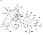
- each outer conductor L1, L2, L3 ( FIG. 1 shows the example with reference to L1) at least in sections by a first and a second electrical conductor 41, 42 connected in parallel thereto.
- the first conductor 41 forms an inner conductor of a first power cable 51
- the second conductor 42 forms an inner conductor of a second power cable 52.
- the two electrical conductors 41, 42 each have an end region 41a, 42a, which is connected to a contact region 23 of the respective associated reactor tube 20 (cf. FIG. 2 ) is electrically connected.
- the respective end region 41a, 42a is in this case preferably electrically conductively connected via a press or welded connection to the contact region 23 of the associated reactor tube 20.
- the individual contact regions 23 of the reactor tubes 20 each protrude transversely to a longitudinal axis z of the respective reactor tube 20 from a jacket 24 of the respective reactor tube 20 and can be integrally formed on the respective jacket 24 or welded thereto.
- the contact regions 23 are provided outside the combustion chamber 10 on the reactor tubes 20, along the vertical above the combustion chamber 10.
- the reactor tubes 20 and their shells 24 in the region of the respective contact region 23 and above the said wall 13 of the combustion chamber 10th a cross-sectional thickening 25, which in the FIG. 1 is recognizable.
- the resistance of the reactor tubes 20 decreases in the region of the contact regions 23 of the reactor tubes 20, so that excessive heating of the reactor tubes 20 can advantageously be suppressed there.
- first and second conductors 41, 42 For controlling a heat development in the outer conductors L1, L2, L3 or in the first and second conductors 41, 42 (power cable 51, 52) is preferably provided, this with a cooling device K 'or with a fluid coolant W, preferably water, to cool constantly.
- a fluid coolant W preferably water
- the first and second conductors 41, 42 may each themselves form a flow channel S1, S2, which is designed to guide the fluid coolant W.
- the first and the second conductors 41, 42 are each surrounded by a shell 41b, 42b, expediently in the form of insulation of the respective power cable 51, 52.
- the inner conductors 41, 42 and the respective sheath 41b, 42b may define a flow channel S1 or S2, which is adapted to guide the fluid coolant W.
- the two flow channels S1, S2 are at the respective contact region 23 or in the vicinity in flow communication, so that a cooling circuit can be provided for each outer conductor L1, L2, L3, in which the coolant W to the respective contact region 23 out (eg power cable 51 in Fig. 1 ) and away again (eg power cable 52 in Fig. 1 ) can be transported.
- FIG. 3 shows by way of example a possible voltage supply of a furnace according to the invention, wherein the vertical dashed line represents the separation between the region of the furnace 1 and, for example, a switching station.
- a transformer 503 is present, which has, for example, a primary voltage of 690 V and a secondary voltage of 50 V for the respective phase (power consumption 630 kVA).
- the primary voltage eg 690V
- the primary voltage is provided in each case via a line 501 and via a three-phase thyristor 502 to the relevant transformer 503, so that the secondary voltage can be regulated in each case in the range from 30V to 50V.
- the stepped-down three-phase alternating voltage can be determined by means of the said Power cable 51, 52 are provided on the respective reactor tube 20 and contact area 23.
- the length of the power cables 51, 52 may be, for example, in a range of 10m to 20m. Other supply voltage concepts are of course also conceivable.
- the furnace 1 according to the invention is particularly suitable for carrying out the method according to the invention.
- the technical teaching of the present invention makes it possible for the feed stream E in the reactor tubes 20 to be temporarily heated in addition to the furnace, for example, by generating an electric current in the reactor tubes 20 in the manner described above, which heats the reactor tubes 20 for heating the reactor tubes 20 Feed stream E is heated. Furthermore, an electric current can be temporarily generated instead of the furnace, which heats the reactor tubes 20 for heating the feed stream E.
- the invention thus advantageously makes it possible to include excess energy, in particular renewable (electrical) energy, in the process of steam reforming.
Landscapes
- Chemical & Material Sciences (AREA)
- Chemical Kinetics & Catalysis (AREA)
- Organic Chemistry (AREA)
- Health & Medical Sciences (AREA)
- General Health & Medical Sciences (AREA)
- Engineering & Computer Science (AREA)
- Combustion & Propulsion (AREA)
- Inorganic Chemistry (AREA)
- Toxicology (AREA)
- Hydrogen, Water And Hydrids (AREA)
- Devices And Processes Conducted In The Presence Of Fluids And Solid Particles (AREA)
Claims (15)
- Four de reformage à la vapeur d'un flux de charge (E) contenant un hydrocarbure, de préférence du méthane, comprenant :- une chambre de combustion (10),- une pluralité de tubes de réacteur (20) disposés dans la chambre de combustion (10) pour accueillir un catalyseur (K) ainsi que pour faire passer le flux de charge (E) à travers les tubes de réacteur (20),- au moins un brûleur (30) qui est configuré pour brûler un combustible dans la chambre de combustion (10) en vue de chauffer les tubes de réacteur (20),caractérisé en ce que
le four, en plus de l'au moins un brûleur (30), possède au moins une source de tension (2) qui est reliée à la pluralité de tubes de réacteur (20) de telle sorte qu'un courant électrique peut à chaque fois être généré dans les tubes de réacteur (20), lequel chauffe les tubes de réacteur (20) en vue de chauffer la charge (E). - Four selon la revendication 1, caractérisé en ce que le four possède M conducteurs extérieurs, l'au moins une source de tension (2) étant configurée pour délivrer une tension alternative aux M conducteurs extérieurs (L1, ..., LM), M étant un nombre entier naturel supérieur ou égal à deux, et les tensions alternatives respectives étant déphasées de 2π/M les unes par rapport aux autres.
- Four selon l'une des revendications précédentes, caractérisé en ce que les tubes de réacteur (20) débouchent dans un collecteur (21).
- Four selon l'une des revendications 2 et 3, caractérisé en ce que les conducteurs extérieurs (L1, ..., LM) sont respectivement reliés de manière électriquement conductrice avec un tube de réacteur (20) associé de la pluralité de tubes de réacteur (20), de manière à former un circuit en étoile dans lequel le point central (S) est formé par le collecteur (21).
- Four selon la revendication 2 ou l'une des revendications 3 à 4 en référence à la revendication 2, caractérisé en ce que chaque conducteur extérieur (L1, ..., LM) possède une zone d'extrémité par le biais de laquelle il est relié de manière électriquement conductrice avec une zone de contact (23) du tube de réacteur (20) associé.
- Four selon la revendication 2 ou l'une des revendications 3 à 5 dans le mesure où elle se réfère à la revendication 2, caractérisé en ce que chaque conducteur extérieur (L1, ..., LM) possède au moins dans certaines portions un premier conducteur électrique et un deuxième conducteur électrique (41, 42) branché en parallèle à celui-ci, les deux conducteurs électriques (41, 42) possédant respectivement une zone d'extrémité (41a, 42a) qui est reliée de manière électriquement conductrice avec une zone de contact (23) du tube de réacteur (20) associé.
- Four selon la revendication 5 ou 6, caractérisé en ce que la zone d'extrémité (41a, 42a) correspondante est reliée à la zone de contact (23) du tube de réacteur (20) associé par le biais d'une liaison par pressage ou d'une liaison soudée.
- Four selon l'une des revendications 5 à 7, caractérisé en ce que les zones de contact (23) font respectivement saillie d'une enveloppe (24) du tube de réacteur (20) correspondant transversalement par rapport à un axe longitudinal (z) du tube de réacteur (20) correspondant.
- Four selon l'une des revendications 5 à 8, caractérisé en ce que les zones de contact (23) se trouvent en-dehors de la chambre de combustion (10) ainsi qu'au-dessus de la chambre de combustion (10), sur les tubes de réacteur (23).
- Four selon l'une des revendications précédentes, caractérisé en ce que les tubes de réacteur (20) possèdent un épaississement de la section transversale (25) au niveau de la zone de contact (23) correspondante.
- Four selon l'une des revendications précédentes, caractérisé en ce qu'il existe un dispositif de refroidissement (K') qui est configuré pour refroidir les conducteurs extérieurs (L1, ..., L2) ou les premier et deuxième conducteurs électriques (41, 42) au moyen d'un agent réfrigérant (W) fluide.
- Four selon la revendication 11, caractérisé en ce que les conducteurs extérieurs (L1, ..., L3) ou les premier et deuxième conducteurs (41, 42) forment respectivement un canal d'écoulement qui est configuré pour conduire l'agent réfrigérant (W) fluide.
- Four selon la revendication 11, caractérisé en ce que les conducteurs extérieurs (L1, ..., L3) ou les premier et deuxième conducteurs électriques (41, 42) sont respectivement entouré par une gaine (41b, 42b) sous la forme d'une isolation, les gaines (41b, 42b) correspondantes délimitant un canal d'écoulement (S1, S2) qui est configuré pour conduire l'agent réfrigérant (W) fluide.
- Four selon la revendication 6 et selon la revendication 12 ou 13, caractérisé en ce que le canal d'écoulement (S1) associé au premier conducteur (41) respectif se trouve en liaison fluidique avec le canal d'écoulement (S2) associé au deuxième conducteur (42) respectif de manière adjacente à la zone de contact (23), de sorte que l'agent réfrigérant (W) fluide puisse être acheminé vers la zone de contact (23) par le biais d'un canal d'écoulement (S1, S2) et puisse. être évacué de la zone de contact (23) par le biais de l'autre chemin d'écoulement (S2, S1).
- Procédé de reformage à la vapeur en utilisant un four (1) selon l'une des revendications précédentes, un flux de charge (E) contenant un hydrocarbure, de préférence du méthane, possédant de la vapeur d'eau étant conduit à travers les tubes de réacteur (20) d'un four (1) où, en présence d'un catalyseur (K) disposé dans les tubes de réacteur (20), il est convertit en un flux de gaz synthétique brut (R), le flux de charge (E) dans les tubes de réacteur (20) étant conduit à travers une chambre de combustion (10) dans laquelle est brûlé un combustible en vue de chauffer le flux de charge (E),
caractérisé en ce- que le flux de charge (E) est en plus chauffé au moins temporairement dans les tubes de réacteur (20) en ce qu'un courant électrique est respectivement généré dans les tubes de réacteur (20), lequel chauffe les tubes de réacteur (20) en vue de chauffer le flux de charge (E), ou- qu'au lieu du chauffage du flux de charge (E) par la combustion du combustible dans les tubes de réacteur (20), un courant électrique est respectivement généré au moins temporairement, lequel chauffe les tubes de réacteur (20) en vue de chauffer le flux de charge (E).
Applications Claiming Priority (1)
| Application Number | Priority Date | Filing Date | Title |
|---|---|---|---|
| DE102015004121.5A DE102015004121A1 (de) | 2015-03-31 | 2015-03-31 | Ofen mit elektrisch sowie mittels Brennstoff beheizbaren Reaktorrohren zur Dampfreformierung eines kohlenwasserstoffhaltigen Einsatzes |
Publications (2)
| Publication Number | Publication Date |
|---|---|
| EP3075704A1 EP3075704A1 (fr) | 2016-10-05 |
| EP3075704B1 true EP3075704B1 (fr) | 2017-10-11 |
Family
ID=55802147
Family Applications (1)
| Application Number | Title | Priority Date | Filing Date |
|---|---|---|---|
| EP16000387.7A Active EP3075704B1 (fr) | 2015-03-31 | 2016-02-16 | Four pour le reformage a la vapeur d'hydrocarbures dote de tubes chauffables par combustion et electriquement |
Country Status (5)
| Country | Link |
|---|---|
| US (1) | US9908091B2 (fr) |
| EP (1) | EP3075704B1 (fr) |
| CA (1) | CA2921466C (fr) |
| DE (1) | DE102015004121A1 (fr) |
| RU (1) | RU2712608C2 (fr) |
Cited By (1)
| Publication number | Priority date | Publication date | Assignee | Title |
|---|---|---|---|---|
| US12403439B2 (en) | 2020-10-30 | 2025-09-02 | Gti Energy | Electrically heated reforming reactor for reforming of methane and other hydrocarbons |
Families Citing this family (37)
| Publication number | Priority date | Publication date | Assignee | Title |
|---|---|---|---|---|
| US12455034B2 (en) | 2018-06-26 | 2025-10-28 | Thyssenkrupp Uhde Gmbh | Method for providing synthesis gas by means of an additional electric heater |
| DE102018213463A1 (de) * | 2018-08-10 | 2020-02-13 | Thyssenkrupp Ag | Verfahren zur Bereitstellung von Synthesegas mit Hilfe einer zusätzlichen elektrischen Heizung |
| DE102018210409A1 (de) * | 2018-06-26 | 2020-01-02 | Thyssenkrupp Ag | Verfahren zur Bereitstellung von Synthesegas mit Hilfe einer zusätzlichen induktiven Heizung |
| EP3814274B1 (fr) * | 2018-06-29 | 2022-05-04 | Shell Internationale Research Maatschappij B.V. | Réacteur chauffé électriquement et procédé de conversion de gaz au moyen dudit réacteur |
| AR115969A1 (es) * | 2018-08-31 | 2021-03-17 | Dow Global Technologies Llc | Sistemas y procesos para transferir calor mediante sal fundida durante la mejora de hidrocarburos |
| EP3730456A1 (fr) * | 2019-04-24 | 2020-10-28 | SABIC Global Technologies B.V. | Utilisation d'énergie renouvelable dans la synthèse de l'ammoniac |
| EP3730457A1 (fr) * | 2019-04-24 | 2020-10-28 | SABIC Global Technologies B.V. | Utilisation d'énergie renouvelable dans la synthèse de l'ammoniac |
| EP4081337A1 (fr) * | 2019-12-23 | 2022-11-02 | Shell Internationale Research Maatschappij B.V. | Réacteur chauffé électriquement, et four comprenant ledit réacteur et procédé de conversion de gaz utilisant ledit réacteur |
| EP3862076A1 (fr) | 2020-02-10 | 2021-08-11 | Linde GmbH | Réacteur et procédé de réalisation d'une réaction chimique |
| EP3878546A1 (fr) * | 2020-03-13 | 2021-09-15 | Linde GmbH | Réacteur et procédé de réalisation d'une réaction chimique |
| EP3878547A1 (fr) * | 2020-03-13 | 2021-09-15 | Linde GmbH | Réacteur et procédé de réalisation d'une réaction chimique |
| EP3900818A1 (fr) | 2020-04-23 | 2021-10-27 | Linde GmbH | Réacteur et procédé de réalisation d'une réaction chimique |
| EP3900817A1 (fr) * | 2020-04-23 | 2021-10-27 | Linde GmbH | Réacteur et procédé de réalisation d'une réaction chimique |
| HUE061649T2 (hu) * | 2020-08-07 | 2023-08-28 | Linde Gmbh | Reaktor és eljárás kémiai reakció végrehajtásához |
| EP3974051A1 (fr) * | 2020-09-28 | 2022-03-30 | Linde GmbH | Dispositif et procédé de réalisation réglable d'une réaction chimique |
| ES2947469T3 (es) * | 2020-09-28 | 2023-08-09 | Linde Gmbh | Dispositivo para la realización de una reacción química en un fluido de proceso en una instalación de producción |
| ES2951414T3 (es) * | 2020-11-06 | 2023-10-20 | Linde Gmbh | Reactor para realizar una reacción química |
| WO2022171603A1 (fr) * | 2021-02-10 | 2022-08-18 | Shell Internationale Research Maatschappij B.V. | Appareil chauffé électriquement |
| EP4043100A1 (fr) * | 2021-02-11 | 2022-08-17 | Linde GmbH | Réacteur destiné à la réalisation d'une réaction chimique dans un fluide de processus et procédé |
| EP4056894A1 (fr) | 2021-03-10 | 2022-09-14 | Linde GmbH | Procédé et système pour unité de craquage à vapeur |
| EP4056893A1 (fr) | 2021-03-10 | 2022-09-14 | Linde GmbH | Procédé et système pour unité de craquage à vapeur |
| EP4056892A1 (fr) | 2021-03-10 | 2022-09-14 | Linde GmbH | Procédé et système de vapocraquage |
| CA3212640A1 (fr) * | 2021-04-07 | 2022-10-13 | Linde Gmbh | Procede pour mettre en uvre une reaction chimique et agencement de reacteur |
| CA3215719A1 (fr) | 2021-04-15 | 2022-10-20 | Shell Internationale Research Maatschappij B.V. | Configuration de reacteur modulaire pour la production de produits chimiques avec chauffage electrique pour la mise en oeuvre de reactions |
| US12409426B2 (en) * | 2021-11-22 | 2025-09-09 | Schneider Electric Systems Usa, Inc. | Direct electrical heating of process heater tubes using galvanic isolation techniques |
| US11697099B2 (en) * | 2021-11-22 | 2023-07-11 | Schneider Electric Systems Usa, Inc. | Direct electrical heating of catalytic reactive system |
| CN120769774A (zh) | 2022-12-27 | 2025-10-10 | 根特大学 | 用于热裂化和加热的冲击波反应器 |
| EP4428095A1 (fr) | 2023-03-09 | 2024-09-11 | L'air Liquide, Societe Anonyme Pour L'etude Et L'exploitation Des Procedes Georges Claude | Procédé de production d'hydrogène avec reformage de méthane à la vapeur chauffé électriquement |
| KR20250160180A (ko) | 2023-03-09 | 2025-11-11 | 레르 리키드 쏘시에떼 아노님 뿌르 레뜌드 에렉스뿔라따시옹 데 프로세데 조르즈 클로드 | 전기 가열식 증기 메탄 개질을 이용한 수소 생산 방법 |
| EP4428096A1 (fr) | 2023-03-09 | 2024-09-11 | L'air Liquide, Societe Anonyme Pour L'etude Et L'exploitation Des Procedes Georges Claude | Procédé de production d'hydrogène avec reformage de méthane à la vapeur chauffé électriquement |
| US12302477B2 (en) | 2023-03-24 | 2025-05-13 | Schneider Electric Systems Usa, Inc. | Induction heating for process electrification |
| EP4688648A1 (fr) * | 2023-03-24 | 2026-02-11 | SABIC Global Technologies B.V. | Four électrique à contre-courant et méthodes |
| KR20240175156A (ko) * | 2023-06-12 | 2024-12-19 | 주식회사 엘지화학 | 전기 가열 반응기 |
| WO2025162758A1 (fr) | 2024-01-30 | 2025-08-07 | Shell Internationale Research Maatschappij B.V. | Procédé de production de gaz de synthèse à l'aide de gaz riche en méthane résiduaire comme charge d'alimentation |
| EP4635617A1 (fr) | 2024-04-16 | 2025-10-22 | Linde GmbH | Appareil et procédé de production d'un produit de réaction |
| WO2026068772A1 (fr) | 2024-09-27 | 2026-04-02 | Universiteit Gent | Ensemble de guidage pour turboréacteur à ondes de choc et turboréacteur à ondes de choc comprenant ledit ensemble |
| DK202530282A1 (en) * | 2025-05-06 | 2026-04-23 | Topsoe As | Electrical heating in low carbon processes |
Family Cites Families (12)
| Publication number | Priority date | Publication date | Assignee | Title |
|---|---|---|---|---|
| US3453087A (en) * | 1964-06-25 | 1969-07-01 | Girdler Corp | Modular reformer furnace |
| US3479143A (en) * | 1964-07-13 | 1969-11-18 | Girdler Corp | Means for conducting endothermic catalytic reactions,including electrical heating means |
| US3419362A (en) * | 1965-06-25 | 1968-12-31 | Chemical Construction Corp | Fluid heater |
| CH645318A5 (de) * | 1978-11-21 | 1984-09-28 | Silberring Ludwig | Verfahren und vorrichtung zur herstellung von wasserstoff. |
| US4690743A (en) * | 1985-05-02 | 1987-09-01 | Al-Chem Fuels, Inc. | Method for gas synthesis |
| JPH0913955A (ja) * | 1995-06-27 | 1997-01-14 | Komatsu Ltd | ディーゼルエンジンの排気ガス浄化装置 |
| WO2005001960A2 (fr) * | 2003-06-27 | 2005-01-06 | Ultracell Corporation | Prechauffage de combustible dans des piles a combustible et electronique portable |
| US20050244682A1 (en) * | 2004-04-28 | 2005-11-03 | Meacham G B K | Thermally integrated internal reforming fuel cells |
| JP5055734B2 (ja) * | 2005-09-27 | 2012-10-24 | カシオ計算機株式会社 | 燃料電池用燃料改質器 |
| WO2009102760A1 (fr) * | 2008-02-12 | 2009-08-20 | Genesis Fueltech, Inc. | Reformeur et procédé de démarrage |
| US9011560B2 (en) * | 2009-06-09 | 2015-04-21 | Sundrop Fuels, Inc. | Various methods and apparatuses for an ultra-high heat flux chemical reactor |
| KR101213046B1 (ko) * | 2012-09-18 | 2012-12-18 | 국방과학연구소 | 연료 개질기의 제어 방법 |
-
2015
- 2015-03-31 DE DE102015004121.5A patent/DE102015004121A1/de not_active Withdrawn
-
2016
- 2016-02-16 EP EP16000387.7A patent/EP3075704B1/fr active Active
- 2016-02-22 CA CA2921466A patent/CA2921466C/fr active Active
- 2016-03-03 US US15/059,330 patent/US9908091B2/en active Active
- 2016-03-30 RU RU2016111730A patent/RU2712608C2/ru active
Non-Patent Citations (1)
| Title |
|---|
| None * |
Cited By (1)
| Publication number | Priority date | Publication date | Assignee | Title |
|---|---|---|---|---|
| US12403439B2 (en) | 2020-10-30 | 2025-09-02 | Gti Energy | Electrically heated reforming reactor for reforming of methane and other hydrocarbons |
Also Published As
| Publication number | Publication date |
|---|---|
| RU2016111730A3 (fr) | 2019-07-30 |
| RU2016111730A (ru) | 2017-10-05 |
| CA2921466C (fr) | 2023-03-21 |
| CA2921466A1 (fr) | 2016-09-30 |
| DE102015004121A1 (de) | 2016-10-06 |
| EP3075704A1 (fr) | 2016-10-05 |
| US20160288074A1 (en) | 2016-10-06 |
| RU2712608C2 (ru) | 2020-01-29 |
| US9908091B2 (en) | 2018-03-06 |
Similar Documents
| Publication | Publication Date | Title |
|---|---|---|
| EP3075704B1 (fr) | Four pour le reformage a la vapeur d'hydrocarbures dote de tubes chauffables par combustion et electriquement | |
| EP3837476B1 (fr) | Dispositif et procédé de chauffage d'un fluide dans une conduite avec courant continu | |
| EP3661322B1 (fr) | Procédé de chauffage d'un fluide dans une conduite à courant triphasé | |
| EP4424411B1 (fr) | Réacteur pour réactions endothermiques à haute température | |
| EP4104643A1 (fr) | Dispositif et procédé de chauffage d'un fluide dans un pipeline avec un courant alternatif monophasé | |
| EP4117811B1 (fr) | Réacteur et procédé de réalisation d'une réaction chimique | |
| EP3249027A1 (fr) | Procédé à émissions réduites pour la fabrication d'oléfines | |
| EP4291326B1 (fr) | Réacteur destiné à la réalisation d'une réaction chimique dans un fluide de processus et procédé | |
| EP3153466A1 (fr) | Chauffage inductif d'un four de dispositif de vaporeformage | |
| EP4221886A1 (fr) | Intégration thermique d'un réacteur chauffé électriquement | |
| WO2023046943A1 (fr) | Cylindres multiples | |
| WO2022029270A1 (fr) | Réacteur et procédé pour effectuer une réaction chimique | |
| EP4292700B1 (fr) | Procédé de pyrolyse d'hydrocarbures avec zones de chauffage et de réaction spatialement séparées à l'intérieur de la chambre du réacteur | |
| EP3075705A1 (fr) | Procédé et installation de reformage à la vapeur | |
| DE102015219861A1 (de) | Vorrichtung und Verfahren zur Erzeugung von Synthesegas | |
| WO2024027948A1 (fr) | Procédé et installation pour la mise en œuvre d'une réaction en phase gazeuse | |
| WO2023017121A1 (fr) | Élément en forme de plaque pour modules ou systèmes de réaction et procédés associés | |
| EP4670459A1 (fr) | Dispositif de chauffage de charge d'alimentation | |
| EP4585558A1 (fr) | Procédé et installation de fabrication d'un produit de processus | |
| WO2026077633A1 (fr) | Procédé et installation de reformage à la vapeur et procédé de conversion d'une installation de reformage à la vapeur | |
| EP4316640A1 (fr) | Procédé et installation destinés à la mise en uvre d'une réaction catalytique en phase gazeuse |
Legal Events
| Date | Code | Title | Description |
|---|---|---|---|
| PUAI | Public reference made under article 153(3) epc to a published international application that has entered the european phase |
Free format text: ORIGINAL CODE: 0009012 |
|
| AK | Designated contracting states |
Kind code of ref document: A1 Designated state(s): AL AT BE BG CH CY CZ DE DK EE ES FI FR GB GR HR HU IE IS IT LI LT LU LV MC MK MT NL NO PL PT RO RS SE SI SK SM TR |
|
| AX | Request for extension of the european patent |
Extension state: BA ME |
|
| 17P | Request for examination filed |
Effective date: 20170323 |
|
| RBV | Designated contracting states (corrected) |
Designated state(s): AL AT BE BG CH CY CZ DE DK EE ES FI FR GB GR HR HU IE IS IT LI LT LU LV MC MK MT NL NO PL PT RO RS SE SI SK SM TR |
|
| GRAP | Despatch of communication of intention to grant a patent |
Free format text: ORIGINAL CODE: EPIDOSNIGR1 |
|
| RIC1 | Information provided on ipc code assigned before grant |
Ipc: C01B 3/38 20060101AFI20170524BHEP Ipc: B01J 8/06 20060101ALI20170524BHEP |
|
| INTG | Intention to grant announced |
Effective date: 20170622 |
|
| GRAS | Grant fee paid |
Free format text: ORIGINAL CODE: EPIDOSNIGR3 |
|
| GRAA | (expected) grant |
Free format text: ORIGINAL CODE: 0009210 |
|
| AK | Designated contracting states |
Kind code of ref document: B1 Designated state(s): AL AT BE BG CH CY CZ DE DK EE ES FI FR GB GR HR HU IE IS IT LI LT LU LV MC MK MT NL NO PL PT RO RS SE SI SK SM TR |
|
| REG | Reference to a national code |
Ref country code: GB Ref legal event code: FG4D Free format text: NOT ENGLISH |
|
| REG | Reference to a national code |
Ref country code: CH Ref legal event code: EP |
|
| REG | Reference to a national code |
Ref country code: IE Ref legal event code: FG4D Free format text: LANGUAGE OF EP DOCUMENT: GERMAN |
|
| REG | Reference to a national code |
Ref country code: AT Ref legal event code: REF Ref document number: 935830 Country of ref document: AT Kind code of ref document: T Effective date: 20171115 |
|
| REG | Reference to a national code |
Ref country code: DE Ref legal event code: R096 Ref document number: 502016000185 Country of ref document: DE |
|
| REG | Reference to a national code |
Ref country code: FR Ref legal event code: PLFP Year of fee payment: 3 |
|
| REG | Reference to a national code |
Ref country code: NL Ref legal event code: MP Effective date: 20171011 |
|
| REG | Reference to a national code |
Ref country code: LT Ref legal event code: MG4D |
|
| PG25 | Lapsed in a contracting state [announced via postgrant information from national office to epo] |
Ref country code: NL Free format text: LAPSE BECAUSE OF FAILURE TO SUBMIT A TRANSLATION OF THE DESCRIPTION OR TO PAY THE FEE WITHIN THE PRESCRIBED TIME-LIMIT Effective date: 20171011 |
|
| PG25 | Lapsed in a contracting state [announced via postgrant information from national office to epo] |
Ref country code: LT Free format text: LAPSE BECAUSE OF FAILURE TO SUBMIT A TRANSLATION OF THE DESCRIPTION OR TO PAY THE FEE WITHIN THE PRESCRIBED TIME-LIMIT Effective date: 20171011 Ref country code: NO Free format text: LAPSE BECAUSE OF FAILURE TO SUBMIT A TRANSLATION OF THE DESCRIPTION OR TO PAY THE FEE WITHIN THE PRESCRIBED TIME-LIMIT Effective date: 20180111 Ref country code: SE Free format text: LAPSE BECAUSE OF FAILURE TO SUBMIT A TRANSLATION OF THE DESCRIPTION OR TO PAY THE FEE WITHIN THE PRESCRIBED TIME-LIMIT Effective date: 20171011 Ref country code: FI Free format text: LAPSE BECAUSE OF FAILURE TO SUBMIT A TRANSLATION OF THE DESCRIPTION OR TO PAY THE FEE WITHIN THE PRESCRIBED TIME-LIMIT Effective date: 20171011 Ref country code: ES Free format text: LAPSE BECAUSE OF FAILURE TO SUBMIT A TRANSLATION OF THE DESCRIPTION OR TO PAY THE FEE WITHIN THE PRESCRIBED TIME-LIMIT Effective date: 20171011 |
|
| PG25 | Lapsed in a contracting state [announced via postgrant information from national office to epo] |
Ref country code: BG Free format text: LAPSE BECAUSE OF FAILURE TO SUBMIT A TRANSLATION OF THE DESCRIPTION OR TO PAY THE FEE WITHIN THE PRESCRIBED TIME-LIMIT Effective date: 20180111 Ref country code: LV Free format text: LAPSE BECAUSE OF FAILURE TO SUBMIT A TRANSLATION OF THE DESCRIPTION OR TO PAY THE FEE WITHIN THE PRESCRIBED TIME-LIMIT Effective date: 20171011 Ref country code: HR Free format text: LAPSE BECAUSE OF FAILURE TO SUBMIT A TRANSLATION OF THE DESCRIPTION OR TO PAY THE FEE WITHIN THE PRESCRIBED TIME-LIMIT Effective date: 20171011 Ref country code: GR Free format text: LAPSE BECAUSE OF FAILURE TO SUBMIT A TRANSLATION OF THE DESCRIPTION OR TO PAY THE FEE WITHIN THE PRESCRIBED TIME-LIMIT Effective date: 20180112 Ref country code: RS Free format text: LAPSE BECAUSE OF FAILURE TO SUBMIT A TRANSLATION OF THE DESCRIPTION OR TO PAY THE FEE WITHIN THE PRESCRIBED TIME-LIMIT Effective date: 20171011 Ref country code: IS Free format text: LAPSE BECAUSE OF FAILURE TO SUBMIT A TRANSLATION OF THE DESCRIPTION OR TO PAY THE FEE WITHIN THE PRESCRIBED TIME-LIMIT Effective date: 20180211 |
|
| REG | Reference to a national code |
Ref country code: DE Ref legal event code: R097 Ref document number: 502016000185 Country of ref document: DE |
|
| PG25 | Lapsed in a contracting state [announced via postgrant information from national office to epo] |
Ref country code: EE Free format text: LAPSE BECAUSE OF FAILURE TO SUBMIT A TRANSLATION OF THE DESCRIPTION OR TO PAY THE FEE WITHIN THE PRESCRIBED TIME-LIMIT Effective date: 20171011 Ref country code: DK Free format text: LAPSE BECAUSE OF FAILURE TO SUBMIT A TRANSLATION OF THE DESCRIPTION OR TO PAY THE FEE WITHIN THE PRESCRIBED TIME-LIMIT Effective date: 20171011 Ref country code: SK Free format text: LAPSE BECAUSE OF FAILURE TO SUBMIT A TRANSLATION OF THE DESCRIPTION OR TO PAY THE FEE WITHIN THE PRESCRIBED TIME-LIMIT Effective date: 20171011 Ref country code: CZ Free format text: LAPSE BECAUSE OF FAILURE TO SUBMIT A TRANSLATION OF THE DESCRIPTION OR TO PAY THE FEE WITHIN THE PRESCRIBED TIME-LIMIT Effective date: 20171011 |
|
| PLBE | No opposition filed within time limit |
Free format text: ORIGINAL CODE: 0009261 |
|
| STAA | Information on the status of an ep patent application or granted ep patent |
Free format text: STATUS: NO OPPOSITION FILED WITHIN TIME LIMIT |
|
| PG25 | Lapsed in a contracting state [announced via postgrant information from national office to epo] |
Ref country code: PL Free format text: LAPSE BECAUSE OF FAILURE TO SUBMIT A TRANSLATION OF THE DESCRIPTION OR TO PAY THE FEE WITHIN THE PRESCRIBED TIME-LIMIT Effective date: 20171011 Ref country code: IT Free format text: LAPSE BECAUSE OF FAILURE TO SUBMIT A TRANSLATION OF THE DESCRIPTION OR TO PAY THE FEE WITHIN THE PRESCRIBED TIME-LIMIT Effective date: 20171011 Ref country code: SM Free format text: LAPSE BECAUSE OF FAILURE TO SUBMIT A TRANSLATION OF THE DESCRIPTION OR TO PAY THE FEE WITHIN THE PRESCRIBED TIME-LIMIT Effective date: 20171011 Ref country code: RO Free format text: LAPSE BECAUSE OF FAILURE TO SUBMIT A TRANSLATION OF THE DESCRIPTION OR TO PAY THE FEE WITHIN THE PRESCRIBED TIME-LIMIT Effective date: 20171011 |
|
| 26N | No opposition filed |
Effective date: 20180712 |
|
| PG25 | Lapsed in a contracting state [announced via postgrant information from national office to epo] |
Ref country code: MC Free format text: LAPSE BECAUSE OF FAILURE TO SUBMIT A TRANSLATION OF THE DESCRIPTION OR TO PAY THE FEE WITHIN THE PRESCRIBED TIME-LIMIT Effective date: 20171011 Ref country code: MT Free format text: LAPSE BECAUSE OF FAILURE TO SUBMIT A TRANSLATION OF THE DESCRIPTION OR TO PAY THE FEE WITHIN THE PRESCRIBED TIME-LIMIT Effective date: 20171011 |
|
| REG | Reference to a national code |
Ref country code: IE Ref legal event code: MM4A |
|
| REG | Reference to a national code |
Ref country code: BE Ref legal event code: MM Effective date: 20180228 |
|
| PG25 | Lapsed in a contracting state [announced via postgrant information from national office to epo] |
Ref country code: SI Free format text: LAPSE BECAUSE OF FAILURE TO SUBMIT A TRANSLATION OF THE DESCRIPTION OR TO PAY THE FEE WITHIN THE PRESCRIBED TIME-LIMIT Effective date: 20171011 Ref country code: LU Free format text: LAPSE BECAUSE OF NON-PAYMENT OF DUE FEES Effective date: 20180216 |
|
| PG25 | Lapsed in a contracting state [announced via postgrant information from national office to epo] |
Ref country code: IE Free format text: LAPSE BECAUSE OF NON-PAYMENT OF DUE FEES Effective date: 20180216 |
|
| PG25 | Lapsed in a contracting state [announced via postgrant information from national office to epo] |
Ref country code: BE Free format text: LAPSE BECAUSE OF NON-PAYMENT OF DUE FEES Effective date: 20180228 |
|
| REG | Reference to a national code |
Ref country code: CH Ref legal event code: PL |
|
| PG25 | Lapsed in a contracting state [announced via postgrant information from national office to epo] |
Ref country code: LI Free format text: LAPSE BECAUSE OF NON-PAYMENT OF DUE FEES Effective date: 20190228 Ref country code: CH Free format text: LAPSE BECAUSE OF NON-PAYMENT OF DUE FEES Effective date: 20190228 |
|
| PG25 | Lapsed in a contracting state [announced via postgrant information from national office to epo] |
Ref country code: TR Free format text: LAPSE BECAUSE OF FAILURE TO SUBMIT A TRANSLATION OF THE DESCRIPTION OR TO PAY THE FEE WITHIN THE PRESCRIBED TIME-LIMIT Effective date: 20171011 |
|
| PG25 | Lapsed in a contracting state [announced via postgrant information from national office to epo] |
Ref country code: PT Free format text: LAPSE BECAUSE OF FAILURE TO SUBMIT A TRANSLATION OF THE DESCRIPTION OR TO PAY THE FEE WITHIN THE PRESCRIBED TIME-LIMIT Effective date: 20171011 |
|
| PG25 | Lapsed in a contracting state [announced via postgrant information from national office to epo] |
Ref country code: CY Free format text: LAPSE BECAUSE OF FAILURE TO SUBMIT A TRANSLATION OF THE DESCRIPTION OR TO PAY THE FEE WITHIN THE PRESCRIBED TIME-LIMIT Effective date: 20171011 Ref country code: HU Free format text: LAPSE BECAUSE OF FAILURE TO SUBMIT A TRANSLATION OF THE DESCRIPTION OR TO PAY THE FEE WITHIN THE PRESCRIBED TIME-LIMIT; INVALID AB INITIO Effective date: 20160216 Ref country code: MK Free format text: LAPSE BECAUSE OF NON-PAYMENT OF DUE FEES Effective date: 20171011 |
|
| REG | Reference to a national code |
Ref country code: DE Ref legal event code: R081 Ref document number: 502016000185 Country of ref document: DE Owner name: LINDE GMBH, DE Free format text: FORMER OWNER: LINDE AKTIENGESELLSCHAFT, 80331 MUENCHEN, DE |
|
| PG25 | Lapsed in a contracting state [announced via postgrant information from national office to epo] |
Ref country code: AL Free format text: LAPSE BECAUSE OF FAILURE TO SUBMIT A TRANSLATION OF THE DESCRIPTION OR TO PAY THE FEE WITHIN THE PRESCRIBED TIME-LIMIT Effective date: 20171011 |
|
| GBPC | Gb: european patent ceased through non-payment of renewal fee |
Effective date: 20200216 |
|
| PG25 | Lapsed in a contracting state [announced via postgrant information from national office to epo] |
Ref country code: GB Free format text: LAPSE BECAUSE OF NON-PAYMENT OF DUE FEES Effective date: 20200216 |
|
| REG | Reference to a national code |
Ref country code: AT Ref legal event code: MM01 Ref document number: 935830 Country of ref document: AT Kind code of ref document: T Effective date: 20210216 |
|
| PG25 | Lapsed in a contracting state [announced via postgrant information from national office to epo] |
Ref country code: AT Free format text: LAPSE BECAUSE OF NON-PAYMENT OF DUE FEES Effective date: 20210216 |
|
| PGFP | Annual fee paid to national office [announced via postgrant information from national office to epo] |
Ref country code: DE Payment date: 20260217 Year of fee payment: 11 |
|
| PGFP | Annual fee paid to national office [announced via postgrant information from national office to epo] |
Ref country code: FR Payment date: 20260223 Year of fee payment: 11 |