EP3078516A1 - Endanschlagsystem der federung eines fahrzeugs, das die last des fahrzeugs misst - Google Patents
Endanschlagsystem der federung eines fahrzeugs, das die last des fahrzeugs misst Download PDFInfo
- Publication number
- EP3078516A1 EP3078516A1 EP16159102.9A EP16159102A EP3078516A1 EP 3078516 A1 EP3078516 A1 EP 3078516A1 EP 16159102 A EP16159102 A EP 16159102A EP 3078516 A1 EP3078516 A1 EP 3078516A1
- Authority
- EP
- European Patent Office
- Prior art keywords
- base
- suspension
- stop system
- support plate
- vehicle
- Prior art date
- Legal status (The legal status is an assumption and is not a legal conclusion. Google has not performed a legal analysis and makes no representation as to the accuracy of the status listed.)
- Withdrawn
Links
- 239000000725 suspension Substances 0.000 title claims abstract description 41
- 229920001971 elastomer Polymers 0.000 claims abstract description 7
- 239000000806 elastomer Substances 0.000 claims abstract description 6
- 238000004891 communication Methods 0.000 claims abstract description 4
- 238000005259 measurement Methods 0.000 claims description 8
- 238000006073 displacement reaction Methods 0.000 description 6
- 230000006835 compression Effects 0.000 description 3
- 238000007906 compression Methods 0.000 description 3
- 239000006185 dispersion Substances 0.000 description 2
- 239000013536 elastomeric material Substances 0.000 description 2
- 230000006870 function Effects 0.000 description 2
- 239000000463 material Substances 0.000 description 2
- 229920002635 polyurethane Polymers 0.000 description 2
- 239000004814 polyurethane Substances 0.000 description 2
- 230000000284 resting effect Effects 0.000 description 2
- 230000033228 biological regulation Effects 0.000 description 1
- 230000005489 elastic deformation Effects 0.000 description 1
- 238000011156 evaluation Methods 0.000 description 1
- 230000014759 maintenance of location Effects 0.000 description 1
- 238000004519 manufacturing process Methods 0.000 description 1
- 238000012544 monitoring process Methods 0.000 description 1
- 230000000149 penetrating effect Effects 0.000 description 1
- 239000004033 plastic Substances 0.000 description 1
- 229920003023 plastic Polymers 0.000 description 1
- 230000002035 prolonged effect Effects 0.000 description 1
- 230000001105 regulatory effect Effects 0.000 description 1
- 230000000630 rising effect Effects 0.000 description 1
- 238000007789 sealing Methods 0.000 description 1
- 230000005236 sound signal Effects 0.000 description 1
Images

Classifications
-
- B—PERFORMING OPERATIONS; TRANSPORTING
- B60—VEHICLES IN GENERAL
- B60G—VEHICLE SUSPENSION ARRANGEMENTS
- B60G7/00—Pivoted suspension arms; Accessories thereof
- B60G7/04—Buffer means for limiting movement of arms
-
- B—PERFORMING OPERATIONS; TRANSPORTING
- B60—VEHICLES IN GENERAL
- B60G—VEHICLE SUSPENSION ARRANGEMENTS
- B60G11/00—Resilient suspensions characterised by arrangement, location or kind of springs
- B60G11/32—Resilient suspensions characterised by arrangement, location or kind of springs having springs of different kinds
- B60G11/48—Resilient suspensions characterised by arrangement, location or kind of springs having springs of different kinds not including leaf springs
- B60G11/56—Resilient suspensions characterised by arrangement, location or kind of springs having springs of different kinds not including leaf springs having helical, spiral or coil springs, and also fluid springs
- B60G11/58—Resilient suspensions characterised by arrangement, location or kind of springs having springs of different kinds not including leaf springs having helical, spiral or coil springs, and also fluid springs arranged coaxially
-
- B—PERFORMING OPERATIONS; TRANSPORTING
- B60—VEHICLES IN GENERAL
- B60G—VEHICLE SUSPENSION ARRANGEMENTS
- B60G17/00—Resilient suspensions having means for adjusting the spring or vibration-damper characteristics, for regulating the distance between a supporting surface and a sprung part of vehicle or for locking suspension during use to meet varying vehicular or surface conditions, e.g. due to speed or load
- B60G17/015—Resilient suspensions having means for adjusting the spring or vibration-damper characteristics, for regulating the distance between a supporting surface and a sprung part of vehicle or for locking suspension during use to meet varying vehicular or surface conditions, e.g. due to speed or load the regulating means comprising electric or electronic elements
- B60G17/019—Resilient suspensions having means for adjusting the spring or vibration-damper characteristics, for regulating the distance between a supporting surface and a sprung part of vehicle or for locking suspension during use to meet varying vehicular or surface conditions, e.g. due to speed or load the regulating means comprising electric or electronic elements characterised by the type of sensor or the arrangement thereof
-
- B—PERFORMING OPERATIONS; TRANSPORTING
- B60—VEHICLES IN GENERAL
- B60T—VEHICLE BRAKE CONTROL SYSTEMS OR PARTS THEREOF; BRAKE CONTROL SYSTEMS OR PARTS THEREOF, IN GENERAL; ARRANGEMENT OF BRAKING ELEMENTS ON VEHICLES IN GENERAL; PORTABLE DEVICES FOR PREVENTING UNWANTED MOVEMENT OF VEHICLES; VEHICLE MODIFICATIONS TO FACILITATE COOLING OF BRAKES
- B60T8/00—Arrangements for adjusting wheel-braking force to meet varying vehicular or ground-surface conditions, e.g. limiting or varying distribution of braking force
- B60T8/18—Arrangements for adjusting wheel-braking force to meet varying vehicular or ground-surface conditions, e.g. limiting or varying distribution of braking force responsive to vehicle weight or load, e.g. load distribution
- B60T8/1837—Arrangements for adjusting wheel-braking force to meet varying vehicular or ground-surface conditions, e.g. limiting or varying distribution of braking force responsive to vehicle weight or load, e.g. load distribution characterised by the load-detecting arrangements
- B60T8/1856—Arrangements for detecting suspension spring load
- B60T8/1862—Arrangements for detecting suspension spring load comprising sensors of the type providing a fluid output signal representing the load on the vehicle suspension
-
- B—PERFORMING OPERATIONS; TRANSPORTING
- B60—VEHICLES IN GENERAL
- B60G—VEHICLE SUSPENSION ARRANGEMENTS
- B60G2204/00—Indexing codes related to suspensions per se or to auxiliary parts
- B60G2204/40—Auxiliary suspension parts; Adjustment of suspensions
- B60G2204/45—Stops limiting travel
- B60G2204/4502—Stops limiting travel using resilient buffer
-
- B—PERFORMING OPERATIONS; TRANSPORTING
- B60—VEHICLES IN GENERAL
- B60G—VEHICLE SUSPENSION ARRANGEMENTS
- B60G2400/00—Indexing codes relating to detected, measured or calculated conditions or factors
- B60G2400/50—Pressure
- B60G2400/51—Pressure in suspension unit
-
- B—PERFORMING OPERATIONS; TRANSPORTING
- B60—VEHICLES IN GENERAL
- B60G—VEHICLE SUSPENSION ARRANGEMENTS
- B60G2400/00—Indexing codes relating to detected, measured or calculated conditions or factors
- B60G2400/50—Pressure
- B60G2400/51—Pressure in suspension unit
- B60G2400/512—Pressure in suspension unit in spring
- B60G2400/5122—Fluid spring
- B60G2400/51222—Pneumatic
Definitions
- the present invention relates to a driving abutment of a suspension of a motor vehicle, giving an indication of the load of the vehicle, and a motor vehicle equipped with such abutments.
- Motor vehicles generally comprise for each wheel a suspension comprising a suspension spring, a damper that slows the movement of the suspension, and a stop on which the body comes to support when it reaches the end of the race, to slow down this race then stop it.
- certain vehicles in particular commercial vehicles, may include a system for estimating the total load, making it possible in particular to check whether the load does not exceed the total permissible laden mass, in order to respect this load and to ensure security.
- This measurement system can be produced as an aftermarket kit on the vehicle, including the sensors and wiring for connection to an electronic control unit providing load level information.
- Another known load measurement system comprises a load sensor placed on a support of a helical suspension spring, which makes it possible to measure the actual load applied to this suspension. It is thus possible to evaluate the total load of the vehicle.
- this system comprising a load sensor has a high cost.
- Another type of known load measurement system presented in particular by the document FR-A1-3000701 , comprises a thrust bearing formed by an elastomer block containing a closed cavity, and a means for measuring the pressure in this cavity.
- the present invention is intended to avoid these disadvantages of the prior art, by providing a simple and effective means for estimating the load of a vehicle.
- a stop system for the suspension of a motor vehicle the abutment provided to be surrounded by a helical suspension spring, comprising an elastomer block having a closed upper chamber having a stiffness intended for braking the end of travel of a support of the vehicle body, this chamber being connected to a means for measuring the internal pressure, remarkable in that it comprises a base forming a second chamber in communication with the upper chamber, which is disposed below the support of the suspension spring to be compressed by the load of this spring.
- An advantage of the drive stop system according to the invention is that by measuring the pressure in the two cavities, and from the laws giving the load as a function of the pressure, a simple way is obtained without a displacement sensor. comprising friction, an accurate measurement of the mass of the vehicle applying to both the elements transmitting this load, the spring and the attack stop.
- the drive stop system according to the invention may further comprise one or more of the following features, which may be combined with each other.
- the abutment comprises a support plate inserted between the base of the spring and the base.
- the base of the upper chamber is supported on the support plate.
- the support plate comprises a centering means of the base of the upper chamber.
- the centering means may comprise a circular inner rim of the support plate, forming a cylindrical portion facing upwards.
- the base comprises a centering element of the support plate.
- This centering element can form a cup centered within the base, comprising an upwardly facing circular outer flange, which is fitted into the circular inner flange of the backing plate.
- the upper chamber comprises at its base an outer circular groove receiving the first turn of the suspension spring, to achieve an axial wedging of the spring.
- the pressure measuring means can be connected to that of at least one other stop system to measure the average pressure in these stops connected to each other.
- the invention also relates to a motor vehicle comprising drive stop systems for the suspension, comprising any one of the preceding features
- the figure 1 has a stop system 4 disposed along a principal axis presented vertically in this drawing, comprising an upper closed chamber 10 resting on a base 6, via a support plate 12.
- the chamber 10 and the base 6 are made of elastomer, such as a polyurethane or a rubber.
- a helical suspension spring 2 has an upper end supporting the vehicle body, and a lower end resting on the base 6 of the driving abutment 4, which is itself placed on a surface of the axle of the vehicle 8.
- the support plate 12 comprises a horizontal flat portion forming a washer, comprising in the center an upwardly cylindrical shape forming an inner rim 14 made by folding of this sheet.
- the base of the upper chamber 10 comprises an annular flat portion bearing on the upper face of the washer of the support plate 12, which surrounds an axial bore tightly receiving the cylindrical inner rim 14, to ensure a centering and sealing of this upper chamber.
- the base of the suspension spring 2 surrounding the upper chamber 10 bears on the support plate 12 around this chamber, penetrating radially inwards in the elastomeric material through an outer annular groove 16 formed around this chamber .
- the base of the suspension spring 2 having a first horizontal tightened turn forming almost a complete turn, is introduced into this annular groove 16 by an elastic deformation of the elastomer, which ensures a retention of this spring.
- the base 6 forms a lower chamber having a substantially constant thickness of material, having an annular upper face entirely covered by the support plate 12, and a cylindrical outer contour fitted to the outer diameter of this washer.
- the lower face of the base 6 has, starting from the axis, a vertical tube 20 which goes down through the surface of the axle 8, a part horizontal inner ring 22 forming a slightly raised plateau with respect to this surface, and a substantially planar outer annular portion placed on this surface of the axle, which has a slightly conical shape rising to the sides.
- the inner annular portion 22 supports above a cup 26 comprising a central bore receiving the upper end of the tube 20, and an outer flange 30 facing upwards forming a cylindrical portion having at its base a row of bores 28.
- the cylindrical outer rim 30 of the cup 26 is fitted inside the inner rim 14 of the support plate 12, allowing relative axial sliding, the row of bores 28 remaining above this sheet now permanently communication between the base 6 and the upper chamber 10.
- This guidance of the support plate 12 allows in particular its centering and that of the upper chamber 10, avoiding a lateral sliding during deflections of the suspension.
- the cup 26 can be made of plastics material.
- the vertical tube 20 is extended downwards by a duct connected to a not shown pressure sensor, which sends a signal to an electronic control unit representing the pressure in the set of two closed volumes connected together, the upper volume 10 and the base 6.
- the figure 2 presents the stop system for the unladen vehicle, exerting a moderate load on the suspension.
- the weakly compressed suspension spring 2 transmits the load F0 to the base 6, which applies it to the surface of the axle 8, via the support plate 12.
- the vehicle body is not in contact with the superior room 10.
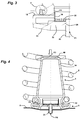
- the figure 3 presents the stop system for the medium-loaded vehicle, exerting a greater load F1 on the suspension, without reaching the upper chamber 10.
- the moderately compressed suspension spring 2 transmits this load to the base 6 by deforming more, which reduces its volume more strongly while the volume of the upper chamber 10 still does not change.
- the reduction of volume of the base 6 causes an average pressure P1 in the stop system 4, which is recorded by the pressure sensor and its electronic box.
- the figure 4 presents the stop system for a heavily loaded vehicle, the body of this vehicle 40 coming into contact above the upper chamber 10 by compressing this volume, in order to deliver an additional support force F3 to this box in addition to that F2 suspension spring 2.
- the electronic box can be connected to driver information means, such as an indicator on the dashboard, or a sound signal.
- the system can signal only an exceeding of the load threshold, keeping in memory the pressure value corresponding to this threshold which has been previously calibrated.
- the system can give a precise indication of the level of charge, if the complete curve of relationship between the pressure and the load has been calibrated.
- Such a type of system can give a precision on the load of the vehicle significantly lower than 50kg, which will be necessary to meet regulatory requirements for monitoring the overload.
Landscapes
- Engineering & Computer Science (AREA)
- Mechanical Engineering (AREA)
- Transportation (AREA)
- Vehicle Body Suspensions (AREA)
- Force Measurement Appropriate To Specific Purposes (AREA)
Applications Claiming Priority (1)
| Application Number | Priority Date | Filing Date | Title |
|---|---|---|---|
| FR1552962A FR3034711B1 (fr) | 2015-04-07 | 2015-04-07 | Systeme de butee d’attaque pour la suspension d'un vehicule mesurant la charge de ce vehicule |
Publications (1)
| Publication Number | Publication Date |
|---|---|
| EP3078516A1 true EP3078516A1 (de) | 2016-10-12 |
Family
ID=53274680
Family Applications (1)
| Application Number | Title | Priority Date | Filing Date |
|---|---|---|---|
| EP16159102.9A Withdrawn EP3078516A1 (de) | 2015-04-07 | 2016-03-08 | Endanschlagsystem der federung eines fahrzeugs, das die last des fahrzeugs misst |
Country Status (2)
| Country | Link |
|---|---|
| EP (1) | EP3078516A1 (de) |
| FR (1) | FR3034711B1 (de) |
Citations (8)
| Publication number | Priority date | Publication date | Assignee | Title |
|---|---|---|---|---|
| FR2554060A1 (fr) * | 1983-10-28 | 1985-05-03 | Renault | Butee de choc additionnelle autogonflable, notamment pour suspension de vehicule automobile |
| EP0262999A1 (de) * | 1986-09-18 | 1988-04-06 | BENDIX France | Lastabhängiges Bremsventil für Fahrzeuge |
| DE3702732A1 (de) * | 1987-01-30 | 1988-08-11 | Teves Gmbh Alfred | Hydraulische ansteuerung, insbesondere fuer bremskraftverteiler mit lastabhaengiger umschaltdruckerhoehung in kraftfahrzeugen |
| EP0283328A1 (de) * | 1987-02-26 | 1988-09-21 | BENDIX France | Lastabhängiges Fahrzeugbremsventil |
| US5467970A (en) * | 1994-06-06 | 1995-11-21 | General Motors Corporation | Vehicle suspension system with jounce bumper |
| JPH09236498A (ja) | 1996-02-29 | 1997-09-09 | Nippon Soken Inc | 荷重検出装置 |
| DE102013210556A1 (de) * | 2012-08-01 | 2014-05-15 | Ford Global Technologies, Llc | Vorrichtung zur Höhenverstellung eines Fahrzeugaufbaus |
| FR3000701A1 (fr) | 2013-01-10 | 2014-07-11 | Peugeot Citroen Automobiles Sa | Butee d'attaque pour la suspension d'un vehicule automobile, comprenant un capteur de pression |
-
2015
- 2015-04-07 FR FR1552962A patent/FR3034711B1/fr active Active
-
2016
- 2016-03-08 EP EP16159102.9A patent/EP3078516A1/de not_active Withdrawn
Patent Citations (8)
| Publication number | Priority date | Publication date | Assignee | Title |
|---|---|---|---|---|
| FR2554060A1 (fr) * | 1983-10-28 | 1985-05-03 | Renault | Butee de choc additionnelle autogonflable, notamment pour suspension de vehicule automobile |
| EP0262999A1 (de) * | 1986-09-18 | 1988-04-06 | BENDIX France | Lastabhängiges Bremsventil für Fahrzeuge |
| DE3702732A1 (de) * | 1987-01-30 | 1988-08-11 | Teves Gmbh Alfred | Hydraulische ansteuerung, insbesondere fuer bremskraftverteiler mit lastabhaengiger umschaltdruckerhoehung in kraftfahrzeugen |
| EP0283328A1 (de) * | 1987-02-26 | 1988-09-21 | BENDIX France | Lastabhängiges Fahrzeugbremsventil |
| US5467970A (en) * | 1994-06-06 | 1995-11-21 | General Motors Corporation | Vehicle suspension system with jounce bumper |
| JPH09236498A (ja) | 1996-02-29 | 1997-09-09 | Nippon Soken Inc | 荷重検出装置 |
| DE102013210556A1 (de) * | 2012-08-01 | 2014-05-15 | Ford Global Technologies, Llc | Vorrichtung zur Höhenverstellung eines Fahrzeugaufbaus |
| FR3000701A1 (fr) | 2013-01-10 | 2014-07-11 | Peugeot Citroen Automobiles Sa | Butee d'attaque pour la suspension d'un vehicule automobile, comprenant un capteur de pression |
Also Published As
| Publication number | Publication date |
|---|---|
| FR3034711A1 (fr) | 2016-10-14 |
| FR3034711B1 (fr) | 2017-04-28 |
Similar Documents
| Publication | Publication Date | Title |
|---|---|---|
| EP3084371B1 (de) | Verfahren und fahrzeug mit einrichtung zur schätzung des gewichts des fahrzeugs | |
| FR2862571A1 (fr) | Systeme pour surveiller un vehicule monte sur pneumatiques, procede d'analyse des signaux ainsi que pneumatique pour vehicule | |
| FR2977831A1 (fr) | Pneu plein de roue d'engin | |
| EP2895826B1 (de) | Vorrichtung und verfahren zur schätzung der ladung eines kraftfahrzeugs | |
| CA2283136A1 (fr) | Insert de securite generant un signal vibratoire transversal et dispositif de detection de la mise en appui d'un pneumatique sur un insert | |
| FR3001541A1 (fr) | Procede de caracterisation du comportement d'un vehicule et application au choix des pneumatiques du vehicule | |
| EP1894800B1 (de) | Fahrzeug mit Mitteln zum Ermitteln einer Neigung, auf die es sich bewegt | |
| EP0606511B1 (de) | Warnvorrichtung und -anlage für Reifenunterdruck und speziell dafür ausgebildetes Rad | |
| FR3072165A1 (fr) | Procede de determination de l'epaisseur d'un pneumatique de vehicule automobile | |
| EP1847823A2 (de) | Reifen versehen mit einem Sensor zwischen der Gehäuseeinlage und dem Innengummi | |
| EP0220115A1 (de) | Verfahren und Vorrichtung zur Überwachung einer Fahrzeugaufhängung mittels Messung des Reibungskoeffizienten des Stossdämpfers | |
| FR3113877A1 (fr) | Procédé pour faire fonctionner un système de détection de poids pour un véhicule à moteur ou une remorque, système de détection de poids correspondant et véhicule à moteur ou remorque | |
| EP3078516A1 (de) | Endanschlagsystem der federung eines fahrzeugs, das die last des fahrzeugs misst | |
| FR2946602A1 (fr) | Procede de commande d'un systeme de freinage. | |
| WO2010116095A1 (fr) | Evaluation d'une deformation peripherique d'un pneumatique en cours d'utilisation | |
| FR3000701A1 (fr) | Butee d'attaque pour la suspension d'un vehicule automobile, comprenant un capteur de pression | |
| FR2996615A1 (fr) | Butee d'attaque pour la suspension d'un vehicule, comportant une premiere raideur lineaire sans hysteresis | |
| EP1673256B1 (de) | Sitzlehnenanordnung für kraftfahrzeug | |
| EP2082939A2 (de) | Verfahren und System zur Abschätzung der Haftung in einem Kraftfahrzeug | |
| EP0220116A1 (de) | Verfahren und Vorrichtung zum Überwachen einer Fahrzeugaufhängung mittels Messung des Reibungskoeffizienten des Dämpfers | |
| FR3144282A1 (fr) | Procédé et dispositif de détection d’un défaut de parallélisme d’un train d’un véhicule. | |
| FR2693273A1 (fr) | Procédé et dispositif pour la détermination de l'accélération d'une superstructure de véhicule. | |
| FR2996637A1 (fr) | Capteur de charge pour une butee d'attaque de suspension, comportant un support coulissant et un capteur | |
| FR2956203A1 (fr) | Dispositif de pesee en temps reel de la charge utile d'un vehicule | |
| FR3055248B1 (fr) | Suspension pour vehicule automobile comportant des jauges de contrainte pour evaluation de la charge |
Legal Events
| Date | Code | Title | Description |
|---|---|---|---|
| PUAI | Public reference made under article 153(3) epc to a published international application that has entered the european phase |
Free format text: ORIGINAL CODE: 0009012 |
|
| AK | Designated contracting states |
Kind code of ref document: A1 Designated state(s): AL AT BE BG CH CY CZ DE DK EE ES FI FR GB GR HR HU IE IS IT LI LT LU LV MC MK MT NL NO PL PT RO RS SE SI SK SM TR |
|
| AX | Request for extension of the european patent |
Extension state: BA ME |
|
| RAP1 | Party data changed (applicant data changed or rights of an application transferred) |
Owner name: PSA AUTOMOBILES SA |
|
| STAA | Information on the status of an ep patent application or granted ep patent |
Free format text: STATUS: THE APPLICATION IS DEEMED TO BE WITHDRAWN |
|
| 18D | Application deemed to be withdrawn |
Effective date: 20170413 |