EP3079451B1 - Ensemble de conversion de puissance refroidie - Google Patents
Ensemble de conversion de puissance refroidie Download PDFInfo
- Publication number
- EP3079451B1 EP3079451B1 EP15162914.4A EP15162914A EP3079451B1 EP 3079451 B1 EP3079451 B1 EP 3079451B1 EP 15162914 A EP15162914 A EP 15162914A EP 3079451 B1 EP3079451 B1 EP 3079451B1
- Authority
- EP
- European Patent Office
- Prior art keywords
- chamber
- cooling
- power conversion
- conversion assembly
- cooling element
- Prior art date
- Legal status (The legal status is an assumption and is not a legal conclusion. Google has not performed a legal analysis and makes no representation as to the accuracy of the status listed.)
- Not-in-force
Links
- 238000006243 chemical reaction Methods 0.000 title claims description 39
- 238000001816 cooling Methods 0.000 claims description 157
- 239000002826 coolant Substances 0.000 claims description 37
- 238000011144 upstream manufacturing Methods 0.000 claims description 3
- 239000003990 capacitor Substances 0.000 claims description 2
- 238000005192 partition Methods 0.000 description 3
- 230000001419 dependent effect Effects 0.000 description 1
- 238000001914 filtration Methods 0.000 description 1
- 239000007788 liquid Substances 0.000 description 1
- 239000004065 semiconductor Substances 0.000 description 1
Images
Classifications
-
- H—ELECTRICITY
- H02—GENERATION; CONVERSION OR DISTRIBUTION OF ELECTRIC POWER
- H02M—APPARATUS FOR CONVERSION BETWEEN AC AND AC, BETWEEN AC AND DC, OR BETWEEN DC AND DC, AND FOR USE WITH MAINS OR SIMILAR POWER SUPPLY SYSTEMS; CONVERSION OF DC OR AC INPUT POWER INTO SURGE OUTPUT POWER; CONTROL OR REGULATION THEREOF
- H02M1/00—Details of apparatus for conversion
-
- H—ELECTRICITY
- H02—GENERATION; CONVERSION OR DISTRIBUTION OF ELECTRIC POWER
- H02M—APPARATUS FOR CONVERSION BETWEEN AC AND AC, BETWEEN AC AND DC, OR BETWEEN DC AND DC, AND FOR USE WITH MAINS OR SIMILAR POWER SUPPLY SYSTEMS; CONVERSION OF DC OR AC INPUT POWER INTO SURGE OUTPUT POWER; CONTROL OR REGULATION THEREOF
- H02M7/00—Conversion of AC power input into DC power output; Conversion of DC power input into AC power output
- H02M7/003—Constructional details, e.g. physical layout, assembly, wiring or busbar connections
-
- H—ELECTRICITY
- H05—ELECTRIC TECHNIQUES NOT OTHERWISE PROVIDED FOR
- H05K—PRINTED CIRCUITS; CASINGS OR CONSTRUCTIONAL DETAILS OF ELECTRIC APPARATUS; MANUFACTURE OF ASSEMBLAGES OF ELECTRICAL COMPONENTS
- H05K7/00—Constructional details common to different types of electric apparatus
- H05K7/20—Modifications to facilitate cooling, ventilating, or heating
- H05K7/20536—Modifications to facilitate cooling, ventilating, or heating for racks or cabinets of standardised dimensions, e.g. electronic racks for aircraft or telecommunication equipment
- H05K7/206—Air circulating in closed loop within cabinets wherein heat is removed through air-to-air heat-exchanger
-
- H—ELECTRICITY
- H05—ELECTRIC TECHNIQUES NOT OTHERWISE PROVIDED FOR
- H05K—PRINTED CIRCUITS; CASINGS OR CONSTRUCTIONAL DETAILS OF ELECTRIC APPARATUS; MANUFACTURE OF ASSEMBLAGES OF ELECTRICAL COMPONENTS
- H05K7/00—Constructional details common to different types of electric apparatus
- H05K7/20—Modifications to facilitate cooling, ventilating, or heating
- H05K7/2089—Modifications to facilitate cooling, ventilating, or heating for power electronics, e.g. for inverters for controlling motor
- H05K7/209—Heat transfer by conduction from internal heat source to heat radiating structure
-
- H—ELECTRICITY
- H05—ELECTRIC TECHNIQUES NOT OTHERWISE PROVIDED FOR
- H05K—PRINTED CIRCUITS; CASINGS OR CONSTRUCTIONAL DETAILS OF ELECTRIC APPARATUS; MANUFACTURE OF ASSEMBLAGES OF ELECTRICAL COMPONENTS
- H05K7/00—Constructional details common to different types of electric apparatus
- H05K7/20—Modifications to facilitate cooling, ventilating, or heating
- H05K7/2089—Modifications to facilitate cooling, ventilating, or heating for power electronics, e.g. for inverters for controlling motor
- H05K7/20909—Forced ventilation, e.g. on heat dissipaters coupled to components
-
- H—ELECTRICITY
- H05—ELECTRIC TECHNIQUES NOT OTHERWISE PROVIDED FOR
- H05K—PRINTED CIRCUITS; CASINGS OR CONSTRUCTIONAL DETAILS OF ELECTRIC APPARATUS; MANUFACTURE OF ASSEMBLAGES OF ELECTRICAL COMPONENTS
- H05K7/00—Constructional details common to different types of electric apparatus
- H05K7/20—Modifications to facilitate cooling, ventilating, or heating
- H05K7/20709—Modifications to facilitate cooling, ventilating, or heating for server racks or cabinets; for data centers, e.g. 19-inch computer racks
- H05K7/20754—Air circulating in closed loop within cabinets
-
- H—ELECTRICITY
- H05—ELECTRIC TECHNIQUES NOT OTHERWISE PROVIDED FOR
- H05K—PRINTED CIRCUITS; CASINGS OR CONSTRUCTIONAL DETAILS OF ELECTRIC APPARATUS; MANUFACTURE OF ASSEMBLAGES OF ELECTRICAL COMPONENTS
- H05K7/00—Constructional details common to different types of electric apparatus
- H05K7/20—Modifications to facilitate cooling, ventilating, or heating
- H05K7/20845—Modifications to facilitate cooling, ventilating, or heating for automotive electronic casings
- H05K7/20854—Heat transfer by conduction from internal heat source to heat radiating structure
-
- H—ELECTRICITY
- H05—ELECTRIC TECHNIQUES NOT OTHERWISE PROVIDED FOR
- H05K—PRINTED CIRCUITS; CASINGS OR CONSTRUCTIONAL DETAILS OF ELECTRIC APPARATUS; MANUFACTURE OF ASSEMBLAGES OF ELECTRICAL COMPONENTS
- H05K7/00—Constructional details common to different types of electric apparatus
- H05K7/20—Modifications to facilitate cooling, ventilating, or heating
- H05K7/20845—Modifications to facilitate cooling, ventilating, or heating for automotive electronic casings
- H05K7/20863—Forced ventilation, e.g. on heat dissipaters coupled to components
Definitions
- the present invention relates to a cooled power conversion assembly.
- a known power conversion assembly comprises heat generating devices in a housing, and at least one heat exchanger adapted to transfer heat out of the housing, the at least one heat exchanger utilizing circulation of liquid coolant.
- document WO 2014/068651 A1 discloses a cooled power conversion assembly adapted to convert electric energy from one form to another, the cooled conversion assembly comprising a chamber, an inverter located in the chamber, cooling means comprising a heat sink adapted to transfer heat out of the chamber and in direct contact with the inverter, wherein the cooled power conversion assembly further comprises a cooling channel extending through the housing, and cooling channel fan means for providing a cooling channel cooling medium flow between a first end of the cooling channel and a second end of the cooling channel.
- An object of the present invention is to provide a cooled power conversion assembly having simple cooling means.
- the objects of the invention are achieved by a cooled power conversion assembly which is characterized by what is stated in the independent claim.
- the preferred embodiments of the invention are disclosed in the dependent claims.
- the invention is based on the idea of using base-to-air cooling elements for cooling high heat density devices of a cooled power conversion assembly, and using air-to-air cooling elements for cooling low heat density devices of the cooled power conversion assembly.
- the cooled power conversion assembly of the invention is simple and inexpensive.
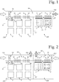
- Figure 1 shows a principle structure of a cooled power conversion assembly comprising a housing 6, a first chamber 100, a second chamber 200, two first type devices 1, six second type devices 2, cooling means for cooling the first chamber and the second chamber, a cooling channel 64, cooling channel fan means 76 and second chamber fan means 72.
- the first chamber 100 and the second chamber 200 are located inside the housing 6.
- the first type devices 1 are located in the first chamber 100, and the second type devices 2 are located in the second chamber 200.
- the cooling means comprises two first cooling elements 3 and two second cooling elements 4. Each first cooling element 3 is adapted to transfer heat out of the first chamber 100. Each first cooling element 3 comprises a first portion 31 located in the first chamber 100 and a second portion 32 located outside the first chamber 100. The first portion 31 of each first cooling element 3 is in direct contact with a corresponding first type device 1. Heat transfer between the first type device 1 and corresponding first cooling element 3 is adapted to take place through heat conduction.
- At least one of the second cooling elements comprises a plurality of individual cooling elements stacked together.
- Each of the plurality of individual cooling elements is adapted to be cooled with substantially the same cooling medium flow.
- the cooling channel 64 extends through the housing 6.
- the cooling channel 64 has a first end 641 and a second end 642.
- the cooling channel fan means 76 is adapted for providing a cooling channel cooling medium flow between the first end 641 of the cooling channel and the second end 642 of the cooling channel.
- the cooling channel cooling medium flow is directed from the first end 641 of the cooling channel towards the second end 642 of the cooling channel.
- the gaseous cooling medium inside the second chamber 200 is air. There is also air inside the first chamber 100 and inside the cooling channel 64.
- the cooling channel fan means 76 sucks air from outside of the housing 6 to the first end 641 of the cooling channel, and blows air to the outside of the housing 6 from the second end 642 of the cooling channel. Since there is air in the cooling channel 64, it can be said that each first cooling element 3 is adapted to function as a base-to-air cooling element, and each second cooling element 4 is adapted to function exclusively as an air-to-air cooling element.
- the second chamber 200 is separated from the first chamber 100 by a separating wall 62. There is substantially no cooling medium flow between the first chamber 100 and the second chamber 200. Each of the first chamber 100 and the second chamber 200 is also separated from the cooling channel 64 and from the outside of the housing 6. The first chamber 100 and the second chamber 200 are ingress protected chambers. There is substantially no cooling medium flow between the first chamber 100 and the cooling channel 64, or between the first chamber 100 and the outside of the housing 6. Also, there is substantially no cooling medium flow between the second chamber 200 and the cooling channel 64, or between the second chamber 200 and the outside of the housing 6. The cooling channel 64 is not an ingress protected channel. In an alternative embodiment a second chamber is only partially separated from the first chamber.
- the second portions 32 of the first cooling elements 3 and the second portions 42 of the second cooling elements 4 are located in the cooling channel 64.
- the second portions 42 of the second cooling elements 4 are located upstream of the second portions 32 of the first cooling elements 3, which means that the second portions 42 of the second cooling elements 4 are located nearer the first end 641 of the cooling channel than the second portions 32 of the first cooling elements 3.
- the second chamber fan means 72 is adapted for providing a second chamber cooling medium flow inside the second chamber 200.
- the second chamber cooling medium flow is adapted to enhance heat transfer from the second type devices 2 to the first portions 41 of the second cooling elements 4. Since the second chamber 200 is separated from the first chamber 100, the second chamber fan means 72 is not adapted for providing a cooling medium flow in the first chamber 100.
- the cooled power conversion assembly of Figure 1 is a cooled frequency converter.
- the first type device 1 on the left comprises a diode module 11 of a rectifier unit.
- the diode module 11 comprises diodes of the rectifier unit, the diodes being adapted to rectify input current of the rectifier unit.
- the diode module 11 is in direct heat transfer contact with the first portion 31 of the first cooling element 3 on the left.
- the first type device 1 on the right comprises a switch module 12 of an inverter unit.
- the switch module 12 comprises controllable switches of the inverter unit, the controllable switches being adapted to invert input current of the inverter unit.
- the controllable switches have high heat density and therefore they require efficient cooling.
- the controllable switches comprise known semiconductor switches such as insulated-gate bipolar transistors, or IGBTs.
- a cooled power conversion assembly is a DC-to-DC converter, an inverter, or some other assembly adapted to convert electric energy from one form to another.
- a DC-to-DC converter, or direct-current converter comprises controllable switches having high heat density.
- heat density of the at least one first type device is higher than heat density of the at least one second type device.
- the at least one first type device comprises a switch module of an inverter unit adapted to feed power from photovoltaic cell means to an electrical network.
- the connection means is adapted for connecting the inverter unit to the photovoltaic cell means and to the electrical network.
- the photovoltaic cell means acts as a supply for the inverter unit, and the electrical network acts as a load for the inverter unit.
- the connection means comprises at least one of the following: a contactor, a switch, a connector and a breaker.
- Each of the first cooling elements 3 and each of the second cooling elements 4 comprises a cooling fin whose second portion is located in the cooling channel 64.
- the cooling fins are adapted to transfer heat into the cooling channel cooling medium flow.
- at least one of the first cooling elements and second cooling elements comprises a thermosiphon such as a compact thermosiphon, or cothex. It is also possible to use a heat pipe of another type.
- the cooling channel 64 is common for the first chamber 100 and the second chamber 200.
- Figure 2 shows a cooled power conversion assembly according to another embodiment of the invention.
- the cooled power conversion assembly of Figure 2 comprises two cooling channels, a first cooling channel 65' for the first chamber 100', and a second cooling channel 66' for the second chamber 200'.
- the first cooling channel 65' is separated from the second cooling channel 66'.
- the cooled power conversion assembly of Figure 2 is similar to the cooled power conversion assembly of Figure 1 .
- the second cooling channel 66' has a first end 661' and a second end 662'. There is a second cooling channel fan means 78' adapted for providing a cooling medium flow between the first end 661' and the second end 662'. The cooling medium flow inside the second cooling channel 66' is directed from the first end 661' towards the second end 662'.
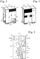
- FIG 3 shows a power converter cabinet comprising a cooled power conversion assembly according to yet another embodiment of the invention.
- the power converter cabinet is depicted from the direction of a first end 641" of a cooling channel.
- the housing 6 comprises a second type device section 702", a control component section 703", an AC cabling section 704", a DC component section 705", a DC cabling section 706", and a cooling channel section 764".
- the second type device section 702" and the DC component section 705" comprise the second chamber 200".
- the cooling channel section 764" comprises the cooling channel.
- FIG 4 the power converter cabinet of Figure 3 is depicted from the direction of a second end 642" of the cooling channel.
- Figure 4 shows that the housing 6" comprises a first chamber section 701 and a filter means section 707".
- the first chamber section 701 comprises a first chamber.
- the power converter cabinet of Figure 3 is a scalable cabinet.
- An end portion comprising the control component section 703" and the AC cabling section 704" is a common part of the cabinet while the rest of the cabinet forms a duplication part which may be duplicated, or multiplied.
- bus bars extend from one duplication part to another.
- FIG 5 shows a simplified internal structure of the power converter cabinet of Figure 3 .
- the power converter cabinet comprises a housing 6", a first chamber 100", a second chamber 200", a third chamber 300", a first type device 1", two second type devices 2", filter means, bus bar means, cooling means for cooling the first chamber and the second chamber, a cooling channel 64" and cooling channel fan means 76".
- the first chamber 100" and the second chamber 200" are located inside the housing 6".
- the first type device 1" is located in the first chamber 100", and the second type devices 2" are located in the second chamber 200".
- the second chamber 200" comprises a partition wall dividing the second chamber 200" into the second type device section 702" and the DC component section 705".
- Figure 5 shows the second type device section of the second chamber 200".
- the partition wall is not depicted in Figure 5 .
- the partition wall extends in a plane parallel to the image plane of Figure 5 .
- the cooling means comprises a first cooling element 3" and a second cooling element 4".
- the first cooling element 3" is adapted to transfer heat out of the first type device 1".
- the first cooling element 3" comprises a first portion 31" located in the first chamber 100" and a second portion 32" located in the cooling channel 64".
- the first portion 31" of the first cooling element 3" is in direct contact with the first type device 1 ".
- the second cooling element 4" is adapted to transfer heat out of the second chamber 200".
- the second cooling element 4" comprises a first portion 41" located in the second chamber 200" and a second portion 42" located in the cooling channel 64".
- the first portion 41" is located between the first chamber 100" and the second chamber 200".
- the second cooling element 4" is in a heat transfer connection with the second type devices 2" exclusively through a gaseous cooling medium.
- the cooling channel 64" extends through the housing 6".
- the cooling channel 64" has a first end 641" and a second end 642".
- the cooling channel fan means 76" is adapted for providing a cooling channel cooling medium flow between the first end 641" of the cooling channel and the second end 642" of the cooling channel.
- the gaseous cooling medium inside the housing 6" is air.
- the cooling channel fan means 76" sucks air from the outside of the housing 6" to the first end 641" of the cooling channel, and blows air to the outside of the housing 6" from the second end 642" of the cooling channel.
- the first cooling element 3" is adapted to function as a base-to-air cooling element
- the second cooling element 4" is adapted to function as an air-to-air cooling element.
- the bus bar means comprises DC bus bars 86" and AC bus bars 88". Both the DC bus bars 86" and the AC bus bars 88" are located in the first chamber 100", in an air circulation channel formed by the first chamber 100".
- Each of the first chamber 100" and the second chamber 200" is separated from the cooling channel 64" and from the outside of the housing 6".
- the first chamber 100" and the second chamber 200" are ingress protected chambers.
- the cooling channel 64" is not an ingress protected channel.
- the second portion 32" of the first cooling element 3" and the second portion 42" of the second cooling element 4" are located in the cooling channel 64".
- the second portion 42" of the second cooling element 4" is located upstream of the second portion 32" of the first cooling element 3".
- the third chamber 300" is separated from the first chamber 100".
- the third chamber 300" comprises a first sub-chamber 301" and a second sub-chamber 302" separated from the first sub-chamber 301".
- the third chamber 300" comprises a third cooling element 303" adapted to transfer heat from the second sub-chamber 302" to the first sub-chamber 301".
- the third cooling element 303" is an air-to-air cooling element.
- the filter means is adapted to improve the quality of power fed from the power conversion assembly by filtering switching frequencies of the power conversion assembly.
- the filter means comprises an LCL filter which is known in the art.
- a capacitor assembly 84" of the filter means is located in the first chamber 100", and is adapted to be cooled by a forced cooling medium flow circulating between the first chamber 100" and the second chamber 200".
- An inductor assembly 82" of the filter means is located in the second sub-chamber 302" of the third chamber 300".
- the forced cooling medium flow circulating between the first chamber 100" and the second chamber 200" is also adapted to cool the second type devices 2" and the bus bar means.
- the forced cooling medium flow also participates, to some extent, in cooling the first type device 1".
- Means for providing the forced cooling medium flow is not depicted in Figure 5 .
Landscapes
- Engineering & Computer Science (AREA)
- Microelectronics & Electronic Packaging (AREA)
- Physics & Mathematics (AREA)
- Thermal Sciences (AREA)
- Power Engineering (AREA)
- Aviation & Aerospace Engineering (AREA)
- Inverter Devices (AREA)
- Cooling Or The Like Of Electrical Apparatus (AREA)
Claims (9)
- Ensemble de conversion de puissance refroidi comprenant :une première chambre (100) ;une deuxième chambre (200) qui est au moins partiellement séparée de la première chambre (100) ;un logement (6) à l'intérieur duquel la première chambre (100) et la deuxième chambre (200) sont situées ;au moins un dispositif de premier type (1) qui est situé dans la première chambre (100) ;au moins un dispositif de second type (2) qui est situé dans la deuxième chambre (200) ; etun moyen de refroidissement qui comprend un premier élément de refroidissement (3) et un deuxième élément de refroidissement (4), le premier élément de refroidissement (3) étant adapté de manière à transférer la chaleur hors de la première chambre (100) et comprenant une première section (31) qui est située dans la première chambre (100) et une seconde section (32) qui est située à l'extérieur de la première chambre (100), le deuxième élément de refroidissement (4) étant adapté de manière à transférer la chaleur hors de la deuxième chambre (200) et comprenant une première section (41) qui est située dans la deuxième chambre (200) et une seconde section (42) qui est située à l'extérieur de la deuxième chambre (200), dans lequel :le premier élément de refroidissement (3) est en contact de transfert thermique direct avec l'au moins un dispositif de premier type (1), et le deuxième élément de refroidissement (4) est en connexion de transfert thermique avec l'au moins un dispositif de second type (2) par l'intermédiaire d'un milieu de refroidissement gazeux ; etl'ensemble de conversion de puissance refroidi comprend un canal de refroidissement (64) qui s'étend au travers du logement (6), et un moyen de ventilateur de canal de refroidissement (76) pour assurer un flux de milieu de refroidissement de canal de refroidissement entre une première extrémité (641) du canal de refroidissement et une seconde extrémité (642) du canal de refroidissement, la seconde section (32) du premier élément de refroidissement (3) étant située au niveau d'un premier site dans le canal de refroidissement (64), la seconde section (42) du deuxième élément de refroidissement (4) étant située au niveau d'un second site dans le canal de refroidissement (64) en amont du premier site ; etl'ensemble de conversion de puissance refroidi est adapté de manière à convertir l'énergie électrique d'une forme selon une autre forme, et une densité thermique de l'au moins un dispositif de premier type (1) est plus élevée qu'une densité thermique de l'au moins un dispositif de second type (2) ; etle premier élément de refroidissement (3) comprend un caloduc ou tube de chauffe ou une ailette de refroidissement, et le deuxième élément de refroidissement (4) comprend un caloduc ou tube de chauffe ou une ailette de refroidissement.
- Ensemble de conversion de puissance refroidi selon la revendication 1, caractérisé en ce que la première chambre (100) et la deuxième chambre (200) sont situées de manière à être adjacentes l'une à l'autre et sont au moins partiellement séparées l'une de l'autre par une paroi de séparation (62).
- Ensemble de conversion de puissance refroidi selon l'une quelconque des revendications précédentes, caractérisé en ce que l'ensemble de conversion de puissance refroidi comprend un moyen de ventilateur de deuxième chambre (72) pour alimenter un flux de milieu de refroidissement de deuxième chambre à l'intérieur de la deuxième chambre (200), le flux de milieu de refroidissement de deuxième chambre étant adapté de manière à augmenter le transfert thermique depuis l'au moins un dispositif de second type (2) jusqu'à la première section (41) du deuxième élément de refroidissement (4).
- Ensemble de conversion de puissance refroidi selon l'une quelconque des revendications précédentes, caractérisé en ce que l'au moins un dispositif de premier type (1) comprend un module de diodes (11) d'une unité de redresseur et/ou un module de commutateurs (12) d'une unité d'inverseur.
- Ensemble de conversion de puissance refroidi selon l'une quelconque des revendications précédentes, caractérisé en ce que l'au moins un dispositif de second type (2) comprend un moyen de protection et/ou un moyen de connexion, le moyen de protection étant adapté pour protéger l'au moins un dispositif de premier type (1), et le moyen de connexion étant adapté pour connecter l'au moins un dispositif de premier type (1) à une alimentation et/ou à une charge.
- Ensemble de conversion de puissance refroidi selon l'une quelconque des revendications précédentes, caractérisé en ce que la première chambre (100) et la deuxième chambre (200) sont des chambres protégées contre les infiltrations.
- Ensemble de conversion de puissance refroidi selon l'une quelconque des revendications précédentes, caractérisé en ce que le premier élément de refroidissement (3) comprend un thermosiphon, et/ou le deuxième élément de refroidissement (4) comprend un thermosiphon.
- Ensemble de conversion de puissance refroidi selon l'une quelconque des revendications précédentes, caractérisé en ce que l'ensemble de conversion de puissance refroidi comprend un moyen de filtre et une troisième chambre (300") qui comprend une première sous-chambre (301"), une seconde sous-chambre (302") qui est séparée de la première sous-chambre (301"), un troisième élément de refroidissement (303") qui est adapté de manière à transférer la chaleur depuis la seconde sous-chambre (302") jusqu' à la première sous-chambre (301"), et un moyen pour assurer un flux de milieu de refroidissement forcé entre l'extérieur du logement (6") et la première sous-chambre (301"), dans lequel un ensemble d'inducteurs (82") du moyen de filtre est situé dans la seconde sous-chambre (302"), et le troisième élément de refroidissement (303") est un élément de refroidissement air-air.
- Ensemble de conversion de puissance refroidi selon la revendication 8, caractérisé en ce que l'ensemble de conversion de puissance refroidi comprend un moyen pour assurer un flux de milieu de refroidissement forcé qui circule entre la première chambre (100") et la deuxième chambre (200"), dans lequel un ensemble de condensateurs (84") du moyen de filtre est situé dans la première chambre (100"), et est adapté de manière à être refroidi par le flux de milieu de refroidissement forcé qui circule entre la première chambre (100"') et la deuxième chambre (200").
Priority Applications (5)
| Application Number | Priority Date | Filing Date | Title |
|---|---|---|---|
| EP15162914.4A EP3079451B1 (fr) | 2015-04-09 | 2015-04-09 | Ensemble de conversion de puissance refroidie |
| US15/082,566 US9974214B2 (en) | 2015-04-09 | 2016-03-28 | Cooled power conversion assembly |
| BR102016007236A BR102016007236A8 (pt) | 2015-04-09 | 2016-03-31 | Montagem de conversão de potência refrigerada |
| CN201610206218.1A CN106059257B (zh) | 2015-04-09 | 2016-04-05 | 冷却式功率转换组件 |
| JP2016077220A JP2016201988A (ja) | 2015-04-09 | 2016-04-07 | 冷却式電力変換アセンブリ |
Applications Claiming Priority (1)
| Application Number | Priority Date | Filing Date | Title |
|---|---|---|---|
| EP15162914.4A EP3079451B1 (fr) | 2015-04-09 | 2015-04-09 | Ensemble de conversion de puissance refroidie |
Publications (2)
| Publication Number | Publication Date |
|---|---|
| EP3079451A1 EP3079451A1 (fr) | 2016-10-12 |
| EP3079451B1 true EP3079451B1 (fr) | 2017-08-02 |
Family
ID=52874975
Family Applications (1)
| Application Number | Title | Priority Date | Filing Date |
|---|---|---|---|
| EP15162914.4A Not-in-force EP3079451B1 (fr) | 2015-04-09 | 2015-04-09 | Ensemble de conversion de puissance refroidie |
Country Status (5)
| Country | Link |
|---|---|
| US (1) | US9974214B2 (fr) |
| EP (1) | EP3079451B1 (fr) |
| JP (1) | JP2016201988A (fr) |
| CN (1) | CN106059257B (fr) |
| BR (1) | BR102016007236A8 (fr) |
Families Citing this family (22)
| Publication number | Priority date | Publication date | Assignee | Title |
|---|---|---|---|---|
| US9795067B2 (en) * | 2015-04-03 | 2017-10-17 | Mitsubishi Electric Corporation | Electronic apparatus |
| JP6768340B2 (ja) * | 2016-04-28 | 2020-10-14 | 株式会社東芝 | 鉄道車両の電力変換装置 |
| US10143116B2 (en) * | 2016-05-13 | 2018-11-27 | Toshiba International Corporation | Outdoor UPS unit system and method |
| JP6927383B2 (ja) * | 2016-06-07 | 2021-08-25 | 富士電機株式会社 | 鉄道車両用電力変換装置 |
| US20180220551A1 (en) * | 2017-01-27 | 2018-08-02 | Vertiv Energy Systems, Inc. | Telecommunications equipment enclosures having heat exchangers |
| JP6828516B2 (ja) * | 2017-03-02 | 2021-02-10 | ダイキン工業株式会社 | 電力変換装置 |
| CN109039493B (zh) | 2017-09-08 | 2020-06-16 | 华为技术有限公司 | Rssi测量方法及网络设备、终端设备 |
| JP7122184B2 (ja) * | 2018-07-13 | 2022-08-19 | 株式会社日立インダストリアルプロダクツ | 電力変換装置 |
| US11240932B1 (en) * | 2018-07-27 | 2022-02-01 | Waymo Llc | Cold plate |
| BR112021018207A2 (pt) * | 2019-03-18 | 2021-11-23 | Dcbel Inc | Sistema de resfriamento para uso em conversores de potência |
| US11503746B2 (en) * | 2019-06-14 | 2022-11-15 | Dmytro KHACHATUROV | Variable frequency drive and method of its air cooling |
| EP3859914A1 (fr) * | 2020-01-29 | 2021-08-04 | ABB Schweiz AG | Compartiment destiné à un appareillage de commutation moyenne tension isolé par air ou par gaz |
| WO2021223106A1 (fr) * | 2020-05-06 | 2021-11-11 | 华为数字能源技术有限公司 | Armoire de dissipation de chaleur et dispositif de communication |
| CN212970506U (zh) * | 2020-05-27 | 2021-04-13 | 阳光电源股份有限公司 | 散热系统及功率柜 |
| US11330734B2 (en) * | 2020-05-28 | 2022-05-10 | Htc Corporation | Case assembly and electronic device |
| CN112217264B (zh) * | 2020-10-21 | 2024-11-19 | 阳光电源股份有限公司 | 一种充电桩及其充电单元 |
| CN112449555A (zh) * | 2020-10-23 | 2021-03-05 | 远景能源有限公司 | 一种大功率逆变器用主动热虹吸散热系统 |
| EP4254782A4 (fr) * | 2020-12-22 | 2024-01-17 | Huawei Digital Power Technologies Co., Ltd. | Convertisseur de courant, échangeurs de chaleur, dissipateurs de chaleur et système de production d'énergie photovoltaïque |
| US11342731B1 (en) | 2021-01-19 | 2022-05-24 | Peopleflo Manufacturing, Inc. | Electrical control panel with cooling system |
| CN112867366A (zh) * | 2021-02-19 | 2021-05-28 | 阳光电源股份有限公司 | 机柜风道、机柜总成及光伏逆变器 |
| CN112996327B (zh) * | 2021-02-19 | 2023-08-15 | 阳光电源股份有限公司 | 一种功率柜 |
| FR3149750B1 (fr) | 2023-06-12 | 2025-06-20 | Staubli Sa Ets | Armoire de contrôleur de robot et robot comprenant une telle armoire |
Family Cites Families (14)
| Publication number | Priority date | Publication date | Assignee | Title |
|---|---|---|---|---|
| US3829740A (en) * | 1973-07-09 | 1974-08-13 | Buehler Corp | Cooling arrangement for a direct current power supply |
| JPS52127771U (fr) * | 1976-03-26 | 1977-09-28 | ||
| JPS52127771A (en) | 1976-04-20 | 1977-10-26 | Matsushita Electric Ind Co Ltd | Patern formation method of tin oxide film |
| JPH02118379A (ja) | 1988-10-26 | 1990-05-02 | Fanuc Ltd | 電子機器の冷却装置 |
| DE9111434U1 (de) * | 1991-09-12 | 1991-12-05 | Elpro AG Berlin - Industrieelektronik und Anlagenbau -, O-1140 Berlin | Einrichtung zum Wärmetransport aus Gefäßen |
| JPH09246767A (ja) | 1996-03-05 | 1997-09-19 | Hitachi Ltd | 電気車用電力変換装置 |
| JP3739486B2 (ja) * | 1996-06-13 | 2006-01-25 | 富士通株式会社 | 屋外設置型キャビネット |
| US5934079A (en) * | 1997-09-09 | 1999-08-10 | Samsung Electronics Co., Ltd. | Base station heat management system |
| JP5210997B2 (ja) | 2009-08-28 | 2013-06-12 | 株式会社日立製作所 | 冷却システム、及び、それを用いる電子装置 |
| US8335081B2 (en) * | 2010-07-16 | 2012-12-18 | Rockwell Automation Technologies, Inc. | Heat sink cooling arrangement for multiple power electronic circuits |
| CN102355149A (zh) * | 2011-10-18 | 2012-02-15 | 华为技术有限公司 | 逆变器、密封风道和散热系统 |
| JP2013193632A (ja) | 2012-03-22 | 2013-09-30 | Mitsubishi Heavy Ind Ltd | 冷却システム |
| JP5914689B2 (ja) * | 2012-10-30 | 2016-05-11 | 株式会社三社電機製作所 | ファン制御装置及びパワーコンディショナー |
| KR20150011176A (ko) | 2013-07-22 | 2015-01-30 | 엘에스산전 주식회사 | 냉각 장치 |
-
2015
- 2015-04-09 EP EP15162914.4A patent/EP3079451B1/fr not_active Not-in-force
-
2016
- 2016-03-28 US US15/082,566 patent/US9974214B2/en active Active
- 2016-03-31 BR BR102016007236A patent/BR102016007236A8/pt not_active Application Discontinuation
- 2016-04-05 CN CN201610206218.1A patent/CN106059257B/zh active Active
- 2016-04-07 JP JP2016077220A patent/JP2016201988A/ja active Pending
Non-Patent Citations (1)
| Title |
|---|
| None * |
Also Published As
| Publication number | Publication date |
|---|---|
| CN106059257B (zh) | 2019-06-21 |
| CN106059257A (zh) | 2016-10-26 |
| BR102016007236A2 (pt) | 2016-11-01 |
| US9974214B2 (en) | 2018-05-15 |
| US20160302330A1 (en) | 2016-10-13 |
| BR102016007236A8 (pt) | 2017-12-19 |
| JP2016201988A (ja) | 2016-12-01 |
| EP3079451A1 (fr) | 2016-10-12 |
Similar Documents
| Publication | Publication Date | Title |
|---|---|---|
| EP3079451B1 (fr) | Ensemble de conversion de puissance refroidie | |
| CN101834560B (zh) | 用于电动机控制器的装置 | |
| US6822850B2 (en) | Laminated bus bar for use with a power conversion configuration | |
| EP2830404B1 (fr) | Dispositif de refroidissement | |
| US6885553B2 (en) | Bus bar assembly for use with a compact power conversion assembly | |
| US6721181B1 (en) | Elongated heat sink for use in converter assemblies | |
| US7068507B2 (en) | Compact liquid converter assembly | |
| US8169780B2 (en) | Power conversion device | |
| JP5407275B2 (ja) | 電力変換装置 | |
| US8854807B2 (en) | Converter arrangement with an air cooling system | |
| JP6631431B2 (ja) | 電力変換装置 | |
| CN110520982A (zh) | 半导体布置 | |
| US6956742B2 (en) | Compact liquid converter assembly | |
| JPWO2006103721A1 (ja) | 電力変換装置の冷却構造 | |
| JPH08294266A (ja) | パワーモジュール及び電力変換装置 | |
| JP5712750B2 (ja) | 電力変換装置 | |
| JP5787105B2 (ja) | 電力変換装置 | |
| KR102653325B1 (ko) | 전기자동차 또는 하이브리드 자동차의 전력변환장치 하우징 | |
| JP2019221048A (ja) | 電力変換装置 | |
| JP6115430B2 (ja) | 電力変換装置 | |
| WO2019244502A1 (fr) | Convertisseur de courant électrique | |
| CN103687441A (zh) | 带有足够精确测定的热交换器的冷却回路 | |
| JP3186715U (ja) | 大電流用整流器 | |
| CA3244492A1 (fr) | Moteur électrique | |
| WO2021220640A1 (fr) | Dispositif de conversion d'énergie |
Legal Events
| Date | Code | Title | Description |
|---|---|---|---|
| PUAI | Public reference made under article 153(3) epc to a published international application that has entered the european phase |
Free format text: ORIGINAL CODE: 0009012 |
|
| 17P | Request for examination filed |
Effective date: 20160901 |
|
| AK | Designated contracting states |
Kind code of ref document: A1 Designated state(s): AL AT BE BG CH CY CZ DE DK EE ES FI FR GB GR HR HU IE IS IT LI LT LU LV MC MK MT NL NO PL PT RO RS SE SI SK SM TR |
|
| AX | Request for extension of the european patent |
Extension state: BA ME |
|
| GRAP | Despatch of communication of intention to grant a patent |
Free format text: ORIGINAL CODE: EPIDOSNIGR1 |
|
| INTG | Intention to grant announced |
Effective date: 20170222 |
|
| RAP1 | Party data changed (applicant data changed or rights of an application transferred) |
Owner name: ABB SCHWEIZ AG |
|
| GRAS | Grant fee paid |
Free format text: ORIGINAL CODE: EPIDOSNIGR3 |
|
| GRAA | (expected) grant |
Free format text: ORIGINAL CODE: 0009210 |
|
| AK | Designated contracting states |
Kind code of ref document: B1 Designated state(s): AL AT BE BG CH CY CZ DE DK EE ES FI FR GB GR HR HU IE IS IT LI LT LU LV MC MK MT NL NO PL PT RO RS SE SI SK SM TR |
|
| REG | Reference to a national code |
Ref country code: CH Ref legal event code: EP Ref country code: AT Ref legal event code: REF Ref document number: 915760 Country of ref document: AT Kind code of ref document: T Effective date: 20170815 |
|
| REG | Reference to a national code |
Ref country code: IE Ref legal event code: FG4D |
|
| REG | Reference to a national code |
Ref country code: DE Ref legal event code: R096 Ref document number: 602015003814 Country of ref document: DE |
|
| REG | Reference to a national code |
Ref country code: NL Ref legal event code: MP Effective date: 20170802 |
|
| REG | Reference to a national code |
Ref country code: AT Ref legal event code: MK05 Ref document number: 915760 Country of ref document: AT Kind code of ref document: T Effective date: 20170802 |
|
| REG | Reference to a national code |
Ref country code: LT Ref legal event code: MG4D |
|
| PG25 | Lapsed in a contracting state [announced via postgrant information from national office to epo] |
Ref country code: HR Free format text: LAPSE BECAUSE OF FAILURE TO SUBMIT A TRANSLATION OF THE DESCRIPTION OR TO PAY THE FEE WITHIN THE PRESCRIBED TIME-LIMIT Effective date: 20170802 Ref country code: NO Free format text: LAPSE BECAUSE OF FAILURE TO SUBMIT A TRANSLATION OF THE DESCRIPTION OR TO PAY THE FEE WITHIN THE PRESCRIBED TIME-LIMIT Effective date: 20171102 Ref country code: NL Free format text: LAPSE BECAUSE OF FAILURE TO SUBMIT A TRANSLATION OF THE DESCRIPTION OR TO PAY THE FEE WITHIN THE PRESCRIBED TIME-LIMIT Effective date: 20170802 Ref country code: LT Free format text: LAPSE BECAUSE OF FAILURE TO SUBMIT A TRANSLATION OF THE DESCRIPTION OR TO PAY THE FEE WITHIN THE PRESCRIBED TIME-LIMIT Effective date: 20170802 Ref country code: AT Free format text: LAPSE BECAUSE OF FAILURE TO SUBMIT A TRANSLATION OF THE DESCRIPTION OR TO PAY THE FEE WITHIN THE PRESCRIBED TIME-LIMIT Effective date: 20170802 Ref country code: SE Free format text: LAPSE BECAUSE OF FAILURE TO SUBMIT A TRANSLATION OF THE DESCRIPTION OR TO PAY THE FEE WITHIN THE PRESCRIBED TIME-LIMIT Effective date: 20170802 Ref country code: FI Free format text: LAPSE BECAUSE OF FAILURE TO SUBMIT A TRANSLATION OF THE DESCRIPTION OR TO PAY THE FEE WITHIN THE PRESCRIBED TIME-LIMIT Effective date: 20170802 |
|
| PG25 | Lapsed in a contracting state [announced via postgrant information from national office to epo] |
Ref country code: ES Free format text: LAPSE BECAUSE OF FAILURE TO SUBMIT A TRANSLATION OF THE DESCRIPTION OR TO PAY THE FEE WITHIN THE PRESCRIBED TIME-LIMIT Effective date: 20170802 Ref country code: IS Free format text: LAPSE BECAUSE OF FAILURE TO SUBMIT A TRANSLATION OF THE DESCRIPTION OR TO PAY THE FEE WITHIN THE PRESCRIBED TIME-LIMIT Effective date: 20171202 Ref country code: PL Free format text: LAPSE BECAUSE OF FAILURE TO SUBMIT A TRANSLATION OF THE DESCRIPTION OR TO PAY THE FEE WITHIN THE PRESCRIBED TIME-LIMIT Effective date: 20170802 Ref country code: LV Free format text: LAPSE BECAUSE OF FAILURE TO SUBMIT A TRANSLATION OF THE DESCRIPTION OR TO PAY THE FEE WITHIN THE PRESCRIBED TIME-LIMIT Effective date: 20170802 Ref country code: RS Free format text: LAPSE BECAUSE OF FAILURE TO SUBMIT A TRANSLATION OF THE DESCRIPTION OR TO PAY THE FEE WITHIN THE PRESCRIBED TIME-LIMIT Effective date: 20170802 Ref country code: BG Free format text: LAPSE BECAUSE OF FAILURE TO SUBMIT A TRANSLATION OF THE DESCRIPTION OR TO PAY THE FEE WITHIN THE PRESCRIBED TIME-LIMIT Effective date: 20171102 Ref country code: GR Free format text: LAPSE BECAUSE OF FAILURE TO SUBMIT A TRANSLATION OF THE DESCRIPTION OR TO PAY THE FEE WITHIN THE PRESCRIBED TIME-LIMIT Effective date: 20171103 |
|
| REG | Reference to a national code |
Ref country code: FR Ref legal event code: PLFP Year of fee payment: 4 |
|
| PG25 | Lapsed in a contracting state [announced via postgrant information from national office to epo] |
Ref country code: DK Free format text: LAPSE BECAUSE OF FAILURE TO SUBMIT A TRANSLATION OF THE DESCRIPTION OR TO PAY THE FEE WITHIN THE PRESCRIBED TIME-LIMIT Effective date: 20170802 Ref country code: CZ Free format text: LAPSE BECAUSE OF FAILURE TO SUBMIT A TRANSLATION OF THE DESCRIPTION OR TO PAY THE FEE WITHIN THE PRESCRIBED TIME-LIMIT Effective date: 20170802 |
|
| REG | Reference to a national code |
Ref country code: DE Ref legal event code: R097 Ref document number: 602015003814 Country of ref document: DE |
|
| PG25 | Lapsed in a contracting state [announced via postgrant information from national office to epo] |
Ref country code: SM Free format text: LAPSE BECAUSE OF FAILURE TO SUBMIT A TRANSLATION OF THE DESCRIPTION OR TO PAY THE FEE WITHIN THE PRESCRIBED TIME-LIMIT Effective date: 20170802 Ref country code: SK Free format text: LAPSE BECAUSE OF FAILURE TO SUBMIT A TRANSLATION OF THE DESCRIPTION OR TO PAY THE FEE WITHIN THE PRESCRIBED TIME-LIMIT Effective date: 20170802 Ref country code: EE Free format text: LAPSE BECAUSE OF FAILURE TO SUBMIT A TRANSLATION OF THE DESCRIPTION OR TO PAY THE FEE WITHIN THE PRESCRIBED TIME-LIMIT Effective date: 20170802 |
|
| PLBE | No opposition filed within time limit |
Free format text: ORIGINAL CODE: 0009261 |
|
| STAA | Information on the status of an ep patent application or granted ep patent |
Free format text: STATUS: NO OPPOSITION FILED WITHIN TIME LIMIT |
|
| 26N | No opposition filed |
Effective date: 20180503 |
|
| PG25 | Lapsed in a contracting state [announced via postgrant information from national office to epo] |
Ref country code: SI Free format text: LAPSE BECAUSE OF FAILURE TO SUBMIT A TRANSLATION OF THE DESCRIPTION OR TO PAY THE FEE WITHIN THE PRESCRIBED TIME-LIMIT Effective date: 20170802 |
|
| PG25 | Lapsed in a contracting state [announced via postgrant information from national office to epo] |
Ref country code: MC Free format text: LAPSE BECAUSE OF FAILURE TO SUBMIT A TRANSLATION OF THE DESCRIPTION OR TO PAY THE FEE WITHIN THE PRESCRIBED TIME-LIMIT Effective date: 20170802 |
|
| REG | Reference to a national code |
Ref country code: BE Ref legal event code: MM Effective date: 20180430 |
|
| REG | Reference to a national code |
Ref country code: IE Ref legal event code: MM4A |
|
| PG25 | Lapsed in a contracting state [announced via postgrant information from national office to epo] |
Ref country code: LU Free format text: LAPSE BECAUSE OF NON-PAYMENT OF DUE FEES Effective date: 20180409 |
|
| PG25 | Lapsed in a contracting state [announced via postgrant information from national office to epo] |
Ref country code: BE Free format text: LAPSE BECAUSE OF NON-PAYMENT OF DUE FEES Effective date: 20180430 |
|
| PG25 | Lapsed in a contracting state [announced via postgrant information from national office to epo] |
Ref country code: IE Free format text: LAPSE BECAUSE OF NON-PAYMENT OF DUE FEES Effective date: 20180409 |
|
| PG25 | Lapsed in a contracting state [announced via postgrant information from national office to epo] |
Ref country code: MT Free format text: LAPSE BECAUSE OF NON-PAYMENT OF DUE FEES Effective date: 20180409 |
|
| PG25 | Lapsed in a contracting state [announced via postgrant information from national office to epo] |
Ref country code: TR Free format text: LAPSE BECAUSE OF FAILURE TO SUBMIT A TRANSLATION OF THE DESCRIPTION OR TO PAY THE FEE WITHIN THE PRESCRIBED TIME-LIMIT Effective date: 20170802 |
|
| PG25 | Lapsed in a contracting state [announced via postgrant information from national office to epo] |
Ref country code: PT Free format text: LAPSE BECAUSE OF FAILURE TO SUBMIT A TRANSLATION OF THE DESCRIPTION OR TO PAY THE FEE WITHIN THE PRESCRIBED TIME-LIMIT Effective date: 20170802 |
|
| PG25 | Lapsed in a contracting state [announced via postgrant information from national office to epo] |
Ref country code: MK Free format text: LAPSE BECAUSE OF NON-PAYMENT OF DUE FEES Effective date: 20170802 Ref country code: RO Free format text: LAPSE BECAUSE OF FAILURE TO SUBMIT A TRANSLATION OF THE DESCRIPTION OR TO PAY THE FEE WITHIN THE PRESCRIBED TIME-LIMIT Effective date: 20170802 Ref country code: HU Free format text: LAPSE BECAUSE OF FAILURE TO SUBMIT A TRANSLATION OF THE DESCRIPTION OR TO PAY THE FEE WITHIN THE PRESCRIBED TIME-LIMIT; INVALID AB INITIO Effective date: 20150409 Ref country code: CY Free format text: LAPSE BECAUSE OF FAILURE TO SUBMIT A TRANSLATION OF THE DESCRIPTION OR TO PAY THE FEE WITHIN THE PRESCRIBED TIME-LIMIT Effective date: 20170802 |
|
| PG25 | Lapsed in a contracting state [announced via postgrant information from national office to epo] |
Ref country code: AL Free format text: LAPSE BECAUSE OF FAILURE TO SUBMIT A TRANSLATION OF THE DESCRIPTION OR TO PAY THE FEE WITHIN THE PRESCRIBED TIME-LIMIT Effective date: 20170802 |
|
| PGFP | Annual fee paid to national office [announced via postgrant information from national office to epo] |
Ref country code: CH Payment date: 20200420 Year of fee payment: 6 Ref country code: FR Payment date: 20200420 Year of fee payment: 6 |
|
| PGFP | Annual fee paid to national office [announced via postgrant information from national office to epo] |
Ref country code: GB Payment date: 20200427 Year of fee payment: 6 |
|
| REG | Reference to a national code |
Ref country code: DE Ref legal event code: R081 Ref document number: 602015003814 Country of ref document: DE Owner name: MARICI HOLDINGS THE NETHERLANDS B.V., NL Free format text: FORMER OWNER: ABB SCHWEIZ AG, BADEN, CH |
|
| PGFP | Annual fee paid to national office [announced via postgrant information from national office to epo] |
Ref country code: DE Payment date: 20210420 Year of fee payment: 7 Ref country code: IT Payment date: 20210427 Year of fee payment: 7 |
|
| GBPC | Gb: european patent ceased through non-payment of renewal fee |
Effective date: 20210409 |
|
| PG25 | Lapsed in a contracting state [announced via postgrant information from national office to epo] |
Ref country code: CH Free format text: LAPSE BECAUSE OF NON-PAYMENT OF DUE FEES Effective date: 20210430 Ref country code: LI Free format text: LAPSE BECAUSE OF NON-PAYMENT OF DUE FEES Effective date: 20210430 Ref country code: GB Free format text: LAPSE BECAUSE OF NON-PAYMENT OF DUE FEES Effective date: 20210409 Ref country code: FR Free format text: LAPSE BECAUSE OF NON-PAYMENT OF DUE FEES Effective date: 20210430 |
|
| REG | Reference to a national code |
Ref country code: DE Ref legal event code: R119 Ref document number: 602015003814 Country of ref document: DE |
|
| PG25 | Lapsed in a contracting state [announced via postgrant information from national office to epo] |
Ref country code: DE Free format text: LAPSE BECAUSE OF NON-PAYMENT OF DUE FEES Effective date: 20221103 |
|
| PG25 | Lapsed in a contracting state [announced via postgrant information from national office to epo] |
Ref country code: IT Free format text: LAPSE BECAUSE OF NON-PAYMENT OF DUE FEES Effective date: 20220409 |