EP3088901B1 - Dispositif d'analyse automatique et procédé d'analyse - Google Patents
Dispositif d'analyse automatique et procédé d'analyse Download PDFInfo
- Publication number
- EP3088901B1 EP3088901B1 EP14875287.6A EP14875287A EP3088901B1 EP 3088901 B1 EP3088901 B1 EP 3088901B1 EP 14875287 A EP14875287 A EP 14875287A EP 3088901 B1 EP3088901 B1 EP 3088901B1
- Authority
- EP
- European Patent Office
- Prior art keywords
- blood clotting
- sample
- reagent
- reference value
- signal reference
- Prior art date
- Legal status (The legal status is an assumption and is not a legal conclusion. Google has not performed a legal analysis and makes no representation as to the accuracy of the status listed.)
- Active
Links
Images


Classifications
-
- G—PHYSICS
- G01—MEASURING; TESTING
- G01N—INVESTIGATING OR ANALYSING MATERIALS BY DETERMINING THEIR CHEMICAL OR PHYSICAL PROPERTIES
- G01N33/00—Investigating or analysing materials by specific methods not covered by groups G01N1/00 - G01N31/00
- G01N33/48—Biological material, e.g. blood, urine; Haemocytometers
- G01N33/50—Chemical analysis of biological material, e.g. blood, urine; Testing involving biospecific ligand binding methods; Immunological testing
- G01N33/86—Chemical analysis of biological material, e.g. blood, urine; Testing involving biospecific ligand binding methods; Immunological testing involving blood coagulating time or factors, or their receptors
-
- G—PHYSICS
- G01—MEASURING; TESTING
- G01N—INVESTIGATING OR ANALYSING MATERIALS BY DETERMINING THEIR CHEMICAL OR PHYSICAL PROPERTIES
- G01N35/00—Automatic analysis not limited to methods or materials provided for in any single one of groups G01N1/00 - G01N33/00; Handling materials therefor
- G01N35/00584—Control arrangements for automatic analysers
- G01N35/00722—Communications; Identification
-
- G—PHYSICS
- G01—MEASURING; TESTING
- G01N—INVESTIGATING OR ANALYSING MATERIALS BY DETERMINING THEIR CHEMICAL OR PHYSICAL PROPERTIES
- G01N35/00—Automatic analysis not limited to methods or materials provided for in any single one of groups G01N1/00 - G01N33/00; Handling materials therefor
- G01N35/10—Devices for transferring samples or any liquids to, in, or from, the analysis apparatus, e.g. suction devices, injection devices
- G01N35/1065—Multiple transfer devices
-
- G—PHYSICS
- G01—MEASURING; TESTING
- G01N—INVESTIGATING OR ANALYSING MATERIALS BY DETERMINING THEIR CHEMICAL OR PHYSICAL PROPERTIES
- G01N35/00—Automatic analysis not limited to methods or materials provided for in any single one of groups G01N1/00 - G01N33/00; Handling materials therefor
- G01N35/00584—Control arrangements for automatic analysers
- G01N35/00594—Quality control, including calibration or testing of components of the analyser
- G01N35/00693—Calibration
- G01N2035/00702—Curve-fitting; Parameter matching; Calibration constants
-
- G—PHYSICS
- G01—MEASURING; TESTING
- G01N—INVESTIGATING OR ANALYSING MATERIALS BY DETERMINING THEIR CHEMICAL OR PHYSICAL PROPERTIES
- G01N35/00—Automatic analysis not limited to methods or materials provided for in any single one of groups G01N1/00 - G01N33/00; Handling materials therefor
- G01N35/00584—Control arrangements for automatic analysers
- G01N35/00722—Communications; Identification
- G01N35/00732—Identification of carriers, materials or components in automatic analysers
- G01N2035/00821—Identification of carriers, materials or components in automatic analysers nature of coded information
-
- G—PHYSICS
- G01—MEASURING; TESTING
- G01N—INVESTIGATING OR ANALYSING MATERIALS BY DETERMINING THEIR CHEMICAL OR PHYSICAL PROPERTIES
- G01N35/00—Automatic analysis not limited to methods or materials provided for in any single one of groups G01N1/00 - G01N33/00; Handling materials therefor
- G01N35/00584—Control arrangements for automatic analysers
- G01N35/00722—Communications; Identification
- G01N2035/00891—Displaying information to the operator
- G01N2035/009—Displaying information to the operator alarms, e.g. audible
-
- G—PHYSICS
- G01—MEASURING; TESTING
- G01N—INVESTIGATING OR ANALYSING MATERIALS BY DETERMINING THEIR CHEMICAL OR PHYSICAL PROPERTIES
- G01N35/00—Automatic analysis not limited to methods or materials provided for in any single one of groups G01N1/00 - G01N33/00; Handling materials therefor
- G01N35/00584—Control arrangements for automatic analysers
- G01N35/00722—Communications; Identification
- G01N2035/00891—Displaying information to the operator
- G01N2035/0091—GUI [graphical user interfaces]
-
- G—PHYSICS
- G01—MEASURING; TESTING
- G01N—INVESTIGATING OR ANALYSING MATERIALS BY DETERMINING THEIR CHEMICAL OR PHYSICAL PROPERTIES
- G01N35/00—Automatic analysis not limited to methods or materials provided for in any single one of groups G01N1/00 - G01N33/00; Handling materials therefor
- G01N35/00584—Control arrangements for automatic analysers
- G01N2035/0097—Control arrangements for automatic analysers monitoring reactions as a function of time
-
- G—PHYSICS
- G01—MEASURING; TESTING
- G01N—INVESTIGATING OR ANALYSING MATERIALS BY DETERMINING THEIR CHEMICAL OR PHYSICAL PROPERTIES
- G01N35/00—Automatic analysis not limited to methods or materials provided for in any single one of groups G01N1/00 - G01N33/00; Handling materials therefor
- G01N35/02—Automatic analysis not limited to methods or materials provided for in any single one of groups G01N1/00 - G01N33/00; Handling materials therefor using a plurality of sample containers moved by a conveyor system past one or more treatment or analysis stations
- G01N35/04—Details of the conveyor system
- G01N2035/0439—Rotary sample carriers, i.e. carousels
- G01N2035/0441—Rotary sample carriers, i.e. carousels for samples
-
- G—PHYSICS
- G01—MEASURING; TESTING
- G01N—INVESTIGATING OR ANALYSING MATERIALS BY DETERMINING THEIR CHEMICAL OR PHYSICAL PROPERTIES
- G01N35/00—Automatic analysis not limited to methods or materials provided for in any single one of groups G01N1/00 - G01N33/00; Handling materials therefor
- G01N35/02—Automatic analysis not limited to methods or materials provided for in any single one of groups G01N1/00 - G01N33/00; Handling materials therefor using a plurality of sample containers moved by a conveyor system past one or more treatment or analysis stations
- G01N35/04—Details of the conveyor system
- G01N2035/0439—Rotary sample carriers, i.e. carousels
- G01N2035/0443—Rotary sample carriers, i.e. carousels for reagents
-
- G—PHYSICS
- G01—MEASURING; TESTING
- G01N—INVESTIGATING OR ANALYSING MATERIALS BY DETERMINING THEIR CHEMICAL OR PHYSICAL PROPERTIES
- G01N33/00—Investigating or analysing materials by specific methods not covered by groups G01N1/00 - G01N31/00
- G01N33/48—Biological material, e.g. blood, urine; Haemocytometers
- G01N33/483—Physical analysis of biological material
- G01N33/487—Physical analysis of biological material of liquid biological material
- G01N33/49—Blood
- G01N33/4905—Determining clotting time of blood
-
- G—PHYSICS
- G01—MEASURING; TESTING
- G01N—INVESTIGATING OR ANALYSING MATERIALS BY DETERMINING THEIR CHEMICAL OR PHYSICAL PROPERTIES
- G01N35/00—Automatic analysis not limited to methods or materials provided for in any single one of groups G01N1/00 - G01N33/00; Handling materials therefor
- G01N35/00584—Control arrangements for automatic analysers
- G01N35/00594—Quality control, including calibration or testing of components of the analyser
- G01N35/00693—Calibration
-
- G—PHYSICS
- G01—MEASURING; TESTING
- G01N—INVESTIGATING OR ANALYSING MATERIALS BY DETERMINING THEIR CHEMICAL OR PHYSICAL PROPERTIES
- G01N35/00—Automatic analysis not limited to methods or materials provided for in any single one of groups G01N1/00 - G01N33/00; Handling materials therefor
- G01N35/00584—Control arrangements for automatic analysers
- G01N35/00722—Communications; Identification
- G01N35/00732—Identification of carriers, materials or components in automatic analysers
-
- G—PHYSICS
- G01—MEASURING; TESTING
- G01N—INVESTIGATING OR ANALYSING MATERIALS BY DETERMINING THEIR CHEMICAL OR PHYSICAL PROPERTIES
- G01N35/00—Automatic analysis not limited to methods or materials provided for in any single one of groups G01N1/00 - G01N33/00; Handling materials therefor
- G01N35/10—Devices for transferring samples or any liquids to, in, or from, the analysis apparatus, e.g. suction devices, injection devices
Definitions
- the present invention relates to an automatic analysis device and an analysis method for performing an analysis of a biological sample such as blood or urine, and particularly relates to a device and a method for measuring a blood clotting time or for measuring a cycle time involved in nucleic acid amplification.
- the automatic analysis device there are a biochemical automatic analysis device or the like which performs a quantitative and qualitative analysis of the concentration of a component of a biological sample such as blood or urine in the field of a biochemical test or a hematological test, and the like, a blood clotting time automatic analysis device (hereinafter sometimes referred to as "blood clotting time measuring device”) or the like which measures a blood clotting time, and a nucleic acid amplification test device or the like which measures a cycle time involved in nucleic acid amplification.
- a blood clotting time automatic analysis device hereinafter sometimes referred to as "blood clotting time measuring device”
- nucleic acid amplification test device or the like which measures a cycle time involved in nucleic acid amplification.
- a sample to be tested (which refers to a sample with an unknown concentration such as a patient specimen ordered to be tested, and is hereinafter referred to as "sample with an unknown concentration”) is analyzed.
- Patent document US6524861 discloses an automatic analysis device and a sample analysis method with the features in the precharacterizing portion of the independent claims. Further related automatic analysis devices are disclosed in US 2011/014640 A1 , US4047890 A and US 2010/235103 A1 .
- a measurement result is reported by a blood clotting time (sec), and therefore, reflection of the conditions of the reagent by creating a standard curve again using a standard sample as described above could not be performed. Due to this, it is more important to ascertain the conditions of the reagent using a control sample.
- the reagent in the case of a lyophilized reagent to be used in several items for the blood clotting test reagent, the reagent is dissolved by a user, and therefore, the conditions of the reagent differ due to a variation in the dissolving conditions even if the reagent of the same lot is used. In other words, a difference in the measurement result may sometimes occur depending on the dissolving conditions of the reagent, and therefore, also in such a case, it is more important to ascertain the conditions of the reagent using a control sample. Further, also in a nucleic acid amplification test device or the like, there is an item to report a measurement result by a reaction cycle number without creating a standard curve, and therefore, it has the same problem.
- the invention has been made in view of such circumstances, and has its object to provide an automatic analysis device and an analysis method capable of improving the reliability of the measurement result by ascertaining the conditions of the reagent and the conditions of the device using a sample having a known blood clotting time (hereinafter referred to as "blood clotting time reference sample”) and adjusting the measurement conditions.
- blood clotting time reference sample a sample having a known blood clotting time
- the invention provides the automatic analysis device and the sample analysis method defined in the independent claims. Further advantageous features are set out in the dependent claims.
- the reliability of the measurement result can be improved by ascertaining the conditions of a reagent using a blood clotting time reference sample and setting an appropriate signal reference value for each reagent vessel.
- a blood clotting time measuring device which measures a time from when a reagent and a biological sample (hereinafter simply referred to as "sample") such as blood or urine are mixed to when fibrin is deposited as a blood clotting time in accordance with the amount of optical change will be described.
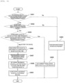
- Fig. 1 is a view schematically showing the entire structure of an automatic analysis device according to this embodiment.
- an automatic analysis device 100 is roughly composed of a sample dispensing probe (sample dispensing mechanism) 101, a sample disk 102, a reagent dispensing probe (reagent dispensing mechanism) 106, a reagent disk 107, a reaction vessel container 111, a gripper 112, a detection unit 113, a waste box 117, an operation section 118, a storage section 119, and a control section 120.
- the sample dispensing probe 101 sucks a sample or a blood clotting time reference sample held in a sample vessel 103 disposed on the sample disk 102 which rotates clockwise and counterclockwise, and discharges the sample into a reaction vessel 104.
- the sample dispensing probe 101 performs a sample suction action and a sample discharge action by the action of a sample syringe pump 105 controlled by the control section 120.
- the reagent dispensing probe 106 sucks a reagent held in a reagent vessel 108 disposed on the reagent disk 107 and discharges the reagent into the reaction vessel 104.
- the reagent dispensing probe 106 performs a reagent suction action and a reagent discharge action by the action of a reagent syringe pump 110 controlled by the control section 120.
- a reagent heating mechanism 109 is included, and the temperature of the reagent sucked by the reagent dispensing probe 106 is increased to a suitable temperature (predetermined temperature) by the reagent heating mechanism 109 controlled by the control section 120.
- the gripper 112 transports and places the reaction vessel 104.
- the gripper 112 transports and places the reaction vessel 104 from the reaction vessel container 111 to a reaction vessel placing section 114 of the detection unit 113 by rotating in a horizontal direction while gripping the reaction vessel 104.
- a detection section (light sensor) 116 is constituted by a photodiode or the like.
- the detection section 116 receives scattered light, which is scattered by the reaction mixture in the reaction vessel 104, converts the light to a current, and outputs the measured light signal indicating the intensity of the received scattered light to an A/D converter 121.
- the measured signal of the scattered light A/D-converted by the A/D converter 121 is input to the control section 120 through an interface 122.
- the action of the detection unit 113 is controlled by the computer 120 for control.
- the gripper 112 grips the reaction vessel 104 after completion of the measurement and disposes of the reaction vessel 104 in the waste box 117.
- An analysis item for a sample to be analyzed by the automatic analysis device 100 is input to the control section 120 from the operation section 118 through a keyboard 118b as an input unit or an operation screen displayed on a display section 118c.
- the device may be configured to use a GUI (Graphical User Interface) for inputting an analysis item by operating an analysis item displayed on the display section 118c with a pointer or the like using a mouse 118a.
- GUI Graphic User Interface
- the overall control section 120a controls the action of the automatic analysis device such as dispensing of the sample or the reagent, transfer of the reaction vessel 104, disposal of the reaction vessel 104, or the like.
- the measurement control section 120b performs a measurement process for measuring the reaction time of a sample based on the result of comparison between a signal reference value having been determined beforehand and a light intensity (signal value) which changes over time in accordance with the degree of the mixing reaction of the sample and the reagent.
- the signal value in this embodiment is a scattered light intensity
- the blood clotting time of the sample is calculated based on the measured light signal from the detection unit 113.
- the calculated blood clotting time is output to the display section 118c and also stored in the storage section 119.
- the clotting time as the calculation result may be printed and output by a printer 123 through the interface 122.
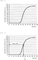
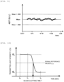
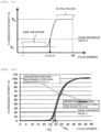
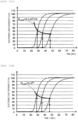
- Fig. 2 is a view showing one example of the change over time in the amount of scattered light detected by the detection unit 113 in the mixing reaction of the sample and the reagent.
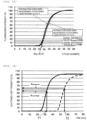
- Fig. 22 shows an example in which the setting of the signal reference value is failed.
- the lower limit of the signal reference value is set to 30%
- the upper limit of the signal reference value is set to 70%
- the expected value Te is set to 31.5 sec.
- a tissue thromboplastin derived from an animal is contained, and in order to maintain stability, a lyophilized reagent is usually used.
- the lyophilized reagent is dissolved manually by a laboratory technician, and therefore, there was a problem that a variation in the measured value due to the preparation error cannot be controlled in the device.
- a mechanism for dispensing a solution and a mechanism for stirring the solution are needed, and therefore, there was a problem that the size of the device is increased and also the cost is increased.
- the information of the expected value Te and the range of variation of the blood clotting time is read and obtained from the bar code of the reagent, a network, or the package insert of the reagent.
- the blood clotting time reference sample of the lot B is measured, and a signal reference value S Local_1 is set (see Fig. 6 ).
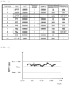
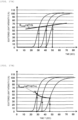
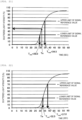
- the blood clotting time reference sample at three concentrations is measured in the reagent vessel 1, and blood clotting times T1 to T3 calculated using a blood clotting reaction curve and the signal reference value S Local_1 are obtained (see Fig. 23A ) .
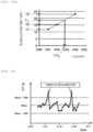
- Plotting is performed on a graph using the obtained T1 to T3, whereby a standard curve is created (see Fig. 24A ).
- the reactivity differs from that in the reagent vessel 1 in a strict sense due to a difference in the amount of water for dissolving the lyophilized reagent or a difference in the storage stability, and therefore, a small difference may occur in some cases.
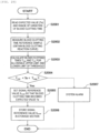
- a more accurate measurement result can be obtained by setting a signal reference value which is different for each reagent vessel from the measurement result of a blood clotting time reference sample even without performing calibration. Also in this case, it is a prerequisite that the range of variation of the signal reference value is in a predetermined range in which the measured value of the blood clotting time reference sample calculated using the same is allowable, and therefore, with respect to the value outside this predetermined range, the signal reference value S Local should not be set. In such a case, according to the flow chart in Fig. 20 , it is desired to issue a system alarm.
- the allowable range of S Local for each item beforehand, it can be determined whether or not the measurement result of the blood clotting time reference sample is in the allowable range, and in the case where the measurement result is outside the allowable range, an alarm is issued, and it is possible to propose the confirmation of the conditions of the reagent and the conditions of the device.
- the signal reference value obtained from the blood clotting reaction curve of the blood clotting time reference sample is in the allowable range of variation is assumed, and the creation of a standard curve for the reagent vessel 2 and the calculation of the concentration of a sample with an unknown concentration will be described with reference to Figs. 25 to 26 .
- the blood clotting time reference sample of the lot B is measured using the reagent of the lot A in the reagent vessel 2, and a signal reference value S Local_2 for the reagent vessel 2 is set (see Fig. 25A ). Subsequently, as shown in Fig.
- S Local_2 is applied to the reaction curve of the blood clotting time reference sample at three concentrations, and blood clotting times T1', T2', and T3' are calculated ( Fig. 25B ).
- the concentration of the standard sample and the obtained T1', T2', and T3' are plotted, whereby the standard curve for the reagent vessel 2 is created ( Fig. 25C ).
- the blood clotting reaction curve of the sample with an unknown concentration is obtained as a blood clotting reaction curve (a) in Fig. 25D
- the blood clotting time Tx obtained using S Local_2 is applied to the standard curve created in Fig. 25C
- the concentration Cx of the sample with an unknown concentration is calculated (see Fig. 25E ).
Landscapes
- Health & Medical Sciences (AREA)
- Life Sciences & Earth Sciences (AREA)
- Chemical & Material Sciences (AREA)
- Immunology (AREA)
- Physics & Mathematics (AREA)
- Analytical Chemistry (AREA)
- Biochemistry (AREA)
- General Health & Medical Sciences (AREA)
- General Physics & Mathematics (AREA)
- Pathology (AREA)
- Engineering & Computer Science (AREA)
- Hematology (AREA)
- Biomedical Technology (AREA)
- Molecular Biology (AREA)
- Urology & Nephrology (AREA)
- Biotechnology (AREA)
- Cell Biology (AREA)
- Microbiology (AREA)
- Food Science & Technology (AREA)
- Medicinal Chemistry (AREA)
- Investigating Or Analysing Biological Materials (AREA)
- Investigating Or Analysing Materials By The Use Of Chemical Reactions (AREA)
- Automatic Analysis And Handling Materials Therefor (AREA)
- Quality & Reliability (AREA)
Claims (12)
- Dispositif (100) d'analyse automatique pour analyser le temps de coagulation du sang d'un échantillon, comprenant :une section (102) de mise en place de récipient pour échantillon dans laquelle un récipient (103) pour échantillon contenant l'échantillon devant être analysé doit être placé ;une section (107) de mise en place de récipient pour réactif dans laquelle un récipient (108) pour réactif contenant un réactif devant être utilisé pour mesurer l'échantillon doit être placé ;un récipient (104) de réaction dans lequel le réactif et l'échantillon doivent être mélangés et fait réagir ;un mécanisme (101) de distribution d'échantillon adapté à distribuer l'échantillon dans le récipient de réaction depuis le récipient pour échantillon ;un mécanisme (106) de distribution de réactif adapté à distribuer le réactif dans le récipient de réaction depuis le récipient pour réactif ;un détecteur (113) adapté à détecter une valeur de signal qui change avec le temps en fonction du degré de la réaction de mélange de l'échantillon et du réactif ; etune section (120) de commande adaptée à analyser l'échantillon sur la base du résultat de la détection,dans lequella valeur de signal est l'une quelconque parmi la quantité de lumière transmise, la quantité de lumière diffusée, la quantité de fluorescence, et la turbidité ; etla section de commande inclut :une section (120c) de commande de paramétrage de valeur de référence de signal adaptée à créer une courbe de réaction de coagulation du sang obtenue à partir de la valeur de signal changeant avec le temps dans une réaction de mélange d'un échantillon de référence de temps de coagulation du sang ayant un temps de coagulation du sang attendu connu et du réactif, et à paramétrer la valeur de la courbe de réaction de coagulation du sang au temps de coagulation du sang attendu connu comme une valeur de référence de signal ;une section (119) de stockage adaptée à stocker la valeur paramétrée de référence de signal en même temps qu'un numéro de lot du réactif comme une information d'identification pour le réactif, etune section de traitement adaptée à déterminer le temps de coagulation du sang de l'échantillon comme l'instant où la valeur de signal détectée par le détecteur excède la valeur de référence de signal stockée,caractérisé en ce que la section de paramétrage de valeur de référence de signal est adaptée à paramétrer une pluralité de valeurs de référence de signal sur la base de la courbe de réaction de l'échantillon de référence de temps de coagulation du sang à une pluralité de concentrations connues, à déterminer une formule approchée à partir d'une relation entre la pluralité paramétrée de valeurs de référence de signal et le temps de coagulation du sang, et à paramétrer une fonction de valeur de référence de signal qui varie selon la concentration de l'échantillon de référence de temps de coagulation du sang sur la base de ladite formule approchée.
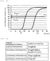
- Dispositif d'analyse automatique selon la revendication 1, dans lequel la formule approchée est formée par un procédé quelconque d'approximation linéaire, d'approximation polynomiale, d'approximation logarithmique, et d'approximation exponentielle.
- Dispositif d'analyse automatique selon la revendication 1, dans lequel la section (120c) de commande de paramétrage de valeur de référence de signal est adaptée à paramétrer la valeur de référence de signal pour chaque récipient (108) pour réactif.
- Dispositif d'analyse automatique selon la revendication 3, dans lequel la section (120) de commande est adaptée à afficher la statut de paramétrage de la valeur de référence de signal pour chaque récipient pour réactif sur une section d'affichage, et à afficher une alarme lorsque la valeur de référence de signal n'a pas été paramétrée.
- Dispositif d'analyse automatique selon la revendication 1, dans lequel la section (120c) de commande de paramétrage de valeur de référence de signal est adaptée à paramétrer une plage dans laquelle la valeur de référence de signal peut être paramétrée en fonction d'un élément d'analyse.
- Dispositif d'analyse automatique selon la revendication 5, dans lequel la section (120c) de commande de paramétrage de valeur de référence de signal est adaptée à déterminer si le temps de coagulation du sang attendu connu est ou non dans la plage dans laquelle la valeur de référence de signal peut être paramétrée, et à émettre une alarme dans le cas où le temps de coagulation du sang attendu connu n'est pas dans la plage dans laquelle la valeur de référence de signal peut être paramétrée.
- Dispositif d'analyse automatique selon la revendication 1, dans lequel la section de commande est adaptée à émettre une alarme lorsque le temps de coagulation du sang attendu connu est à l'extérieur d'une plage ayant été déterminée au préalable.
- Dispositif d'analyse automatique selon la revendication 1,
dans lequel la section (120c) de commande de paramétrage de valeur de référence de signal est adapté à exécuter le processus de paramétrage de valeur de référence de signal sur la base du résultat de détermination que le temps de coagulation du sang attendu connu est ou non à l'extérieur d'une plage ayant été déterminée au préalable. - Dispositif d'analyse automatique selon la revendication 8,
dans lequel la section (120c) de commande de paramétrage de valeur de référence de signal est adapté à exécuter le processus de paramétrage de valeur de référence de signal dans le cas où le temps de coagulation du sang attendu connu est à l'extérieur de la plage ayant été déterminée au préalable comme un résultat de la détermination. - Dispositif d'analyse automatique selon la revendication 1, dans lequel la section de traitement est adaptée à créer une courbe standard à partir de la relation entre le temps de coagulation du sang d'un échantillon de référence de temps de coagulation du sang et la concentration de celui-ci et à déterminer la concentration de l'échantillon sur la base de la courbe standard créée.
- Procédé d'analyse d'échantillon pour analyser le temps de coagulation du sang d'un échantillon, en utilisant le dispositif (100) d'analyse automatique selon l'une quelconque des revendications 1 à 7, le procédé incluant :le paramétrage (S408) d'une pluralité de valeurs de référence de signal sur la base de la courbe de réaction de l'échantillon de référence de temps de coagulation du sang à une pluralité de concentrations connues,la détermination d'une formule approchée à partir d'une relation entre la pluralité paramétrée de valeurs de référence de signal et le temps de coagulation du sang, etle paramétrage d'une fonction de valeur de référence de signal qui varie en fonction de la concentration de l'échantillon de référence de temps de coagulation du sang sur la base de ladite formule approchée.
- Procédé d'analyse d'échantillon selon la revendication 11, dans lequel la formule approchée est formée par un procédé quelconque d'approximation linéaire, d'approximation polynomiale, d'approximation logarithmique, et d'approximation exponentielle.
Applications Claiming Priority (2)
| Application Number | Priority Date | Filing Date | Title |
|---|---|---|---|
| JP2013267309 | 2013-12-25 | ||
| PCT/JP2014/082382 WO2015098473A1 (fr) | 2013-12-25 | 2014-12-08 | Dispositif d'analyse automatique et procédé d'analyse |
Publications (3)
| Publication Number | Publication Date |
|---|---|
| EP3088901A1 EP3088901A1 (fr) | 2016-11-02 |
| EP3088901A4 EP3088901A4 (fr) | 2017-08-23 |
| EP3088901B1 true EP3088901B1 (fr) | 2025-07-02 |
Family
ID=53478338
Family Applications (1)
| Application Number | Title | Priority Date | Filing Date |
|---|---|---|---|
| EP14875287.6A Active EP3088901B1 (fr) | 2013-12-25 | 2014-12-08 | Dispositif d'analyse automatique et procédé d'analyse |
Country Status (5)
| Country | Link |
|---|---|
| US (1) | US10295555B2 (fr) |
| EP (1) | EP3088901B1 (fr) |
| JP (1) | JP6419722B2 (fr) |
| CN (1) | CN106170702B (fr) |
| WO (1) | WO2015098473A1 (fr) |
Families Citing this family (20)
| Publication number | Priority date | Publication date | Assignee | Title |
|---|---|---|---|---|
| JP6563681B2 (ja) * | 2015-05-08 | 2019-08-21 | シスメックス株式会社 | 検体分析装置、血液凝固分析装置、検体分析方法、及びコンピュータプログラム |
| JP6477449B2 (ja) * | 2015-12-07 | 2019-03-06 | ブラザー工業株式会社 | 分析装置、及び、分析方法 |
| CN108603853B (zh) * | 2016-02-10 | 2022-08-09 | 索尼公司 | 电特性测量用样本、电特性测量装置和电特性测量方法 |
| CN108956542A (zh) * | 2017-05-18 | 2018-12-07 | 微采视像科技股份有限公司 | 凝血酶原时间的测定方法及其应用装置 |
| JP6742963B2 (ja) * | 2017-07-25 | 2020-08-19 | 株式会社日立ハイテク | 自動分析装置および画像処理方法 |
| EP3460483B1 (fr) * | 2017-09-26 | 2023-11-01 | F. Hoffmann-La Roche AG | Procédé d'étalonnage |
| JP7267712B2 (ja) * | 2017-10-31 | 2023-05-02 | キヤノンメディカルシステムズ株式会社 | 検量線生成方法、及び自動分析装置 |
| WO2019087367A1 (fr) * | 2017-11-02 | 2019-05-09 | 株式会社島津製作所 | Méthode d'analyse, méthode de création de courbe d'étalonnage et analyseur de coagulation |
| JP7220055B2 (ja) * | 2017-11-07 | 2023-02-09 | 積水メディカル株式会社 | 血液凝固機能の評価方法 |
| JP7235282B2 (ja) * | 2017-11-07 | 2023-03-08 | 積水メディカル株式会社 | 血液凝固機能の評価方法 |
| JP6845199B2 (ja) | 2018-09-28 | 2021-03-17 | シスメックス株式会社 | 表示方法、検体分析装置、コンピュータプログラムおよび記録媒体 |
| WO2020256107A1 (fr) * | 2019-06-20 | 2020-12-24 | 積水メディカル株式会社 | Système d'estimation de facteur de prolongation d'aptt |
| US20220326270A1 (en) * | 2019-06-26 | 2022-10-13 | Hitachi High-Tech Corporation | Automatic analysis device |
| EP4123310B1 (fr) * | 2020-03-19 | 2025-07-09 | Hitachi High-Tech Corporation | Dispositif d'analyse automatique |
| CN112161955B (zh) * | 2020-07-22 | 2024-11-12 | 三诺生物传感股份有限公司 | 一种用于凝血四项的测试方法 |
| CN112924702B (zh) * | 2021-01-25 | 2022-10-25 | 宋世平 | 远程定量系统及方法 |
| CN113484527A (zh) * | 2021-06-23 | 2021-10-08 | 江苏鸿恩医疗器械有限公司 | 一种基于凝血分析仪用试剂的双对数定标方法 |
| CN113484314B (zh) * | 2021-08-16 | 2024-07-12 | 智锐达仪器科技南通有限公司 | 用于农药残留检测仪的检测方法及农药残留检测仪 |
| EP4417978A4 (fr) * | 2021-10-15 | 2025-10-22 | Sekisui Medical Co Ltd | Méthode d'analyse de réaction de coagulation sanguine |
| US20250137993A1 (en) * | 2022-03-09 | 2025-05-01 | Hitachi High-Tech Corporation | Automatic analysis device and automatic analysis method |
Citations (1)
| Publication number | Priority date | Publication date | Assignee | Title |
|---|---|---|---|---|
| US6524861B1 (en) * | 1999-01-22 | 2003-02-25 | Medical Laboratory Automation, Inc. | Blood coagulation analyzer |
Family Cites Families (24)
| Publication number | Priority date | Publication date | Assignee | Title |
|---|---|---|---|---|
| US4047890A (en) * | 1973-11-01 | 1977-09-13 | Bio/Data Corporation | Method and apparatus for determining deficiencies in enzymatic reactors particularly clotting factor levels in blood plasmas |
| JPS51133081A (en) * | 1975-03-21 | 1976-11-18 | Bio Data Corp | Method and apparatus for determination of enzyme reaction in plasma especially of absence of coagulation factor level |
| JPS59228167A (ja) * | 1983-06-09 | 1984-12-21 | Toa Medical Electronics Co Ltd | 血液凝固時間測定装置 |
| JP3036063B2 (ja) | 1990-11-20 | 2000-04-24 | 藤沢薬品工業株式会社 | フィブリンゲル溶解時間の測定方法 |
| US6432657B1 (en) * | 1997-07-23 | 2002-08-13 | Tokuyama Corporation | Method for determining coagulation parameters |
| JP3598019B2 (ja) * | 1999-06-16 | 2004-12-08 | 株式会社日立製作所 | 自動分析装置 |
| JP2001091523A (ja) * | 1999-09-21 | 2001-04-06 | Hitachi Ltd | 自動分析装置 |
| JP2003524184A (ja) * | 2000-02-21 | 2003-08-12 | エフ.ホフマン−ラ ロシュ アーゲー | 血液凝固測定用の電気化学センサー、対応する血液凝固測定システム、および血液凝固測定方法 |
| US20030146113A1 (en) | 2000-02-21 | 2003-08-07 | Volker Unkrig | Electrochemical sensor for determining blood clotting, corresponding system for measuring blood clotting and method for determining blood clotting |
| US20100235103A1 (en) | 2003-05-02 | 2010-09-16 | Carroll Wallace E | Method and apparatus for evaluating prothrombotic conditions |
| JP2005134259A (ja) | 2003-10-30 | 2005-05-26 | Yasunori Yaegashi | 凝固制御物質測定方法 |
| DE102005028018A1 (de) | 2005-06-16 | 2006-12-21 | Dade Behring Marburg Gmbh | Verfahren zur Standardisierung von Gerinnungstesten |
| CN101213437B (zh) * | 2005-07-01 | 2011-10-12 | 希森美康株式会社 | 分析仪 |
| JP4799116B2 (ja) * | 2005-10-11 | 2011-10-26 | シスメックス株式会社 | 検体分析装置、検体分析方法及びコンピュータプログラム |
| JP5134931B2 (ja) | 2007-12-03 | 2013-01-30 | 株式会社日立ハイテクノロジーズ | 自動分析装置 |
| EP2259069B1 (fr) | 2008-03-31 | 2018-09-12 | Sysmex Corporation | Appareil d'analyse de la coagulation du sang et procédé d'analyse de la coagulation du sang |
| JP5183457B2 (ja) * | 2008-12-26 | 2013-04-17 | 株式会社日立ハイテクノロジーズ | 自動分析装置、その支援システム |
| JP5691168B2 (ja) * | 2009-01-08 | 2015-04-01 | ソニー株式会社 | 血液凝固系解析装置、血液凝固系解析方法及びプログラム |
| US20120048036A1 (en) * | 2009-04-09 | 2012-03-01 | Hitachi High-Technologies Corporation | Automatic analysis apparatus |
| EP2508891B1 (fr) | 2009-12-04 | 2019-08-07 | Hitachi High-Technologies Corporation | Analyseur de coagulation sanguine |
| JP5379044B2 (ja) * | 2010-02-25 | 2013-12-25 | 株式会社日立ハイテクノロジーズ | 自動分析装置 |
| JP5658501B2 (ja) | 2010-07-27 | 2015-01-28 | シスメックス株式会社 | 検体分析システム、検体分析装置、管理装置、及び検体分析装置の管理方法 |
| JP2012242122A (ja) | 2011-05-16 | 2012-12-10 | Hitachi High-Technologies Corp | 自動分析装置及び自動分析プログラム |
| JP5911443B2 (ja) * | 2013-03-06 | 2016-04-27 | シスメックス株式会社 | 血液凝固分析装置および血液凝固分析方法 |
-
2014
- 2014-12-08 WO PCT/JP2014/082382 patent/WO2015098473A1/fr not_active Ceased
- 2014-12-08 US US15/032,781 patent/US10295555B2/en active Active
- 2014-12-08 CN CN201480063430.6A patent/CN106170702B/zh active Active
- 2014-12-08 EP EP14875287.6A patent/EP3088901B1/fr active Active
- 2014-12-08 JP JP2015554715A patent/JP6419722B2/ja active Active
Patent Citations (1)
| Publication number | Priority date | Publication date | Assignee | Title |
|---|---|---|---|---|
| US6524861B1 (en) * | 1999-01-22 | 2003-02-25 | Medical Laboratory Automation, Inc. | Blood coagulation analyzer |
Also Published As
| Publication number | Publication date |
|---|---|
| US20160274133A1 (en) | 2016-09-22 |
| CN106170702A (zh) | 2016-11-30 |
| CN106170702B (zh) | 2018-09-21 |
| EP3088901A4 (fr) | 2017-08-23 |
| JP6419722B2 (ja) | 2018-11-14 |
| US10295555B2 (en) | 2019-05-21 |
| JPWO2015098473A1 (ja) | 2017-03-23 |
| EP3088901A1 (fr) | 2016-11-02 |
| WO2015098473A1 (fr) | 2015-07-02 |
Similar Documents
| Publication | Publication Date | Title |
|---|---|---|
| EP3088901B1 (fr) | Dispositif d'analyse automatique et procédé d'analyse | |
| JP7836368B2 (ja) | 自動分析装置及び自動分析方法 | |
| EP3432003B1 (fr) | Dispositif d'analyse automatisé | |
| CN101983338B (zh) | 凝血分析仪、凝血分析方法及计算机程序 | |
| CN108700602B (zh) | 自动分析装置 | |
| US10203277B2 (en) | Automatic analysis device and automatic analysis method | |
| EP3693744A1 (fr) | Analyseur automatique | |
| US20200103428A1 (en) | Calibration curve creation method, analyzer and non-transitory storage medium | |
| CN103765223B (zh) | 自动分析装置 | |
| JP5312834B2 (ja) | 血液凝固分析装置、血液凝固分析方法、及び、コンピュータプログラム | |
| CN118679390A (zh) | 自动分析装置及自动分析方法 | |
| JP2015145836A (ja) | 自動分析装置及び自動分析システム | |
| JP6924600B2 (ja) | 測定方法、測定装置、プログラム、演算式の取得方法および定性判定結果の表示方法 |
Legal Events
| Date | Code | Title | Description |
|---|---|---|---|
| PUAI | Public reference made under article 153(3) epc to a published international application that has entered the european phase |
Free format text: ORIGINAL CODE: 0009012 |
|
| 17P | Request for examination filed |
Effective date: 20160719 |
|
| AK | Designated contracting states |
Kind code of ref document: A1 Designated state(s): AL AT BE BG CH CY CZ DE DK EE ES FI FR GB GR HR HU IE IS IT LI LT LU LV MC MK MT NL NO PL PT RO RS SE SI SK SM TR |
|
| AX | Request for extension of the european patent |
Extension state: BA ME |
|
| DAX | Request for extension of the european patent (deleted) | ||
| A4 | Supplementary search report drawn up and despatched |
Effective date: 20170726 |
|
| RIC1 | Information provided on ipc code assigned before grant |
Ipc: G01N 33/49 20060101ALI20170720BHEP Ipc: G01N 35/00 20060101ALI20170720BHEP Ipc: G01N 33/86 20060101AFI20170720BHEP Ipc: G01N 35/10 20060101ALI20170720BHEP Ipc: G01N 35/04 20060101ALI20170720BHEP |
|
| STAA | Information on the status of an ep patent application or granted ep patent |
Free format text: STATUS: EXAMINATION IS IN PROGRESS |
|
| 17Q | First examination report despatched |
Effective date: 20200519 |
|
| RAP1 | Party data changed (applicant data changed or rights of an application transferred) |
Owner name: HITACHI HIGH-TECH CORPORATION |
|
| GRAP | Despatch of communication of intention to grant a patent |
Free format text: ORIGINAL CODE: EPIDOSNIGR1 |
|
| STAA | Information on the status of an ep patent application or granted ep patent |
Free format text: STATUS: GRANT OF PATENT IS INTENDED |
|
| INTG | Intention to grant announced |
Effective date: 20250408 |
|
| GRAS | Grant fee paid |
Free format text: ORIGINAL CODE: EPIDOSNIGR3 |
|
| GRAA | (expected) grant |
Free format text: ORIGINAL CODE: 0009210 |
|
| STAA | Information on the status of an ep patent application or granted ep patent |
Free format text: STATUS: THE PATENT HAS BEEN GRANTED |
|
| AK | Designated contracting states |
Kind code of ref document: B1 Designated state(s): AL AT BE BG CH CY CZ DE DK EE ES FI FR GB GR HR HU IE IS IT LI LT LU LV MC MK MT NL NO PL PT RO RS SE SI SK SM TR |
|
| REG | Reference to a national code |
Ref country code: GB Ref legal event code: FG4D |
|
| RIN1 | Information on inventor provided before grant (corrected) |
Inventor name: MATSUBARA, SHIGEKI Inventor name: MAKINO, AKIHISA Inventor name: YABUTANI, CHIE |
|
| REG | Reference to a national code |
Ref country code: CH Ref legal event code: EP |
|
| REG | Reference to a national code |
Ref country code: DE Ref legal event code: R096 Ref document number: 602014092095 Country of ref document: DE |
|
| REG | Reference to a national code |
Ref country code: IE Ref legal event code: FG4D |
|
| REG | Reference to a national code |
Ref country code: NL Ref legal event code: MP Effective date: 20250702 |
|
| PG25 | Lapsed in a contracting state [announced via postgrant information from national office to epo] |
Ref country code: PT Free format text: LAPSE BECAUSE OF FAILURE TO SUBMIT A TRANSLATION OF THE DESCRIPTION OR TO PAY THE FEE WITHIN THE PRESCRIBED TIME-LIMIT Effective date: 20251103 |
|
| PG25 | Lapsed in a contracting state [announced via postgrant information from national office to epo] |
Ref country code: NL Free format text: LAPSE BECAUSE OF FAILURE TO SUBMIT A TRANSLATION OF THE DESCRIPTION OR TO PAY THE FEE WITHIN THE PRESCRIBED TIME-LIMIT Effective date: 20250702 |
|
| REG | Reference to a national code |
Ref country code: AT Ref legal event code: MK05 Ref document number: 1809774 Country of ref document: AT Kind code of ref document: T Effective date: 20250702 |
|
| PG25 | Lapsed in a contracting state [announced via postgrant information from national office to epo] |
Ref country code: IS Free format text: LAPSE BECAUSE OF FAILURE TO SUBMIT A TRANSLATION OF THE DESCRIPTION OR TO PAY THE FEE WITHIN THE PRESCRIBED TIME-LIMIT Effective date: 20251102 |
|
| PG25 | Lapsed in a contracting state [announced via postgrant information from national office to epo] |
Ref country code: NO Free format text: LAPSE BECAUSE OF FAILURE TO SUBMIT A TRANSLATION OF THE DESCRIPTION OR TO PAY THE FEE WITHIN THE PRESCRIBED TIME-LIMIT Effective date: 20251002 |
|
| REG | Reference to a national code |
Ref country code: LT Ref legal event code: MG9D |
|
| PG25 | Lapsed in a contracting state [announced via postgrant information from national office to epo] |
Ref country code: AT Free format text: LAPSE BECAUSE OF FAILURE TO SUBMIT A TRANSLATION OF THE DESCRIPTION OR TO PAY THE FEE WITHIN THE PRESCRIBED TIME-LIMIT Effective date: 20250702 |
|
| PG25 | Lapsed in a contracting state [announced via postgrant information from national office to epo] |
Ref country code: FI Free format text: LAPSE BECAUSE OF FAILURE TO SUBMIT A TRANSLATION OF THE DESCRIPTION OR TO PAY THE FEE WITHIN THE PRESCRIBED TIME-LIMIT Effective date: 20250702 |
|
| PG25 | Lapsed in a contracting state [announced via postgrant information from national office to epo] |
Ref country code: HR Free format text: LAPSE BECAUSE OF FAILURE TO SUBMIT A TRANSLATION OF THE DESCRIPTION OR TO PAY THE FEE WITHIN THE PRESCRIBED TIME-LIMIT Effective date: 20250702 |
|
| PG25 | Lapsed in a contracting state [announced via postgrant information from national office to epo] |
Ref country code: GR Free format text: LAPSE BECAUSE OF FAILURE TO SUBMIT A TRANSLATION OF THE DESCRIPTION OR TO PAY THE FEE WITHIN THE PRESCRIBED TIME-LIMIT Effective date: 20251003 |
|
| PG25 | Lapsed in a contracting state [announced via postgrant information from national office to epo] |
Ref country code: CZ Free format text: LAPSE BECAUSE OF FAILURE TO SUBMIT A TRANSLATION OF THE DESCRIPTION OR TO PAY THE FEE WITHIN THE PRESCRIBED TIME-LIMIT Effective date: 20250702 Ref country code: SE Free format text: LAPSE BECAUSE OF FAILURE TO SUBMIT A TRANSLATION OF THE DESCRIPTION OR TO PAY THE FEE WITHIN THE PRESCRIBED TIME-LIMIT Effective date: 20250702 |
|
| PG25 | Lapsed in a contracting state [announced via postgrant information from national office to epo] |
Ref country code: LV Free format text: LAPSE BECAUSE OF FAILURE TO SUBMIT A TRANSLATION OF THE DESCRIPTION OR TO PAY THE FEE WITHIN THE PRESCRIBED TIME-LIMIT Effective date: 20250702 |
|
| PG25 | Lapsed in a contracting state [announced via postgrant information from national office to epo] |
Ref country code: PL Free format text: LAPSE BECAUSE OF FAILURE TO SUBMIT A TRANSLATION OF THE DESCRIPTION OR TO PAY THE FEE WITHIN THE PRESCRIBED TIME-LIMIT Effective date: 20250702 Ref country code: BG Free format text: LAPSE BECAUSE OF FAILURE TO SUBMIT A TRANSLATION OF THE DESCRIPTION OR TO PAY THE FEE WITHIN THE PRESCRIBED TIME-LIMIT Effective date: 20250702 |
|
| PG25 | Lapsed in a contracting state [announced via postgrant information from national office to epo] |
Ref country code: RS Free format text: LAPSE BECAUSE OF FAILURE TO SUBMIT A TRANSLATION OF THE DESCRIPTION OR TO PAY THE FEE WITHIN THE PRESCRIBED TIME-LIMIT Effective date: 20251002 |
|
| PG25 | Lapsed in a contracting state [announced via postgrant information from national office to epo] |
Ref country code: ES Free format text: LAPSE BECAUSE OF FAILURE TO SUBMIT A TRANSLATION OF THE DESCRIPTION OR TO PAY THE FEE WITHIN THE PRESCRIBED TIME-LIMIT Effective date: 20250702 |
|
| PG25 | Lapsed in a contracting state [announced via postgrant information from national office to epo] |
Ref country code: RO Free format text: LAPSE BECAUSE OF FAILURE TO SUBMIT A TRANSLATION OF THE DESCRIPTION OR TO PAY THE FEE WITHIN THE PRESCRIBED TIME-LIMIT Effective date: 20250702 |
|
| PG25 | Lapsed in a contracting state [announced via postgrant information from national office to epo] |
Ref country code: SM Free format text: LAPSE BECAUSE OF FAILURE TO SUBMIT A TRANSLATION OF THE DESCRIPTION OR TO PAY THE FEE WITHIN THE PRESCRIBED TIME-LIMIT Effective date: 20250702 |
|
| PG25 | Lapsed in a contracting state [announced via postgrant information from national office to epo] |
Ref country code: DK Free format text: LAPSE BECAUSE OF FAILURE TO SUBMIT A TRANSLATION OF THE DESCRIPTION OR TO PAY THE FEE WITHIN THE PRESCRIBED TIME-LIMIT Effective date: 20250702 |
|
| PG25 | Lapsed in a contracting state [announced via postgrant information from national office to epo] |
Ref country code: IT Free format text: LAPSE BECAUSE OF FAILURE TO SUBMIT A TRANSLATION OF THE DESCRIPTION OR TO PAY THE FEE WITHIN THE PRESCRIBED TIME-LIMIT Effective date: 20250702 |