EP3141640B1 - Kreuzleger und verfahren zur steuerung eines kreuzlegers - Google Patents
Kreuzleger und verfahren zur steuerung eines kreuzlegers Download PDFInfo
- Publication number
- EP3141640B1 EP3141640B1 EP16186076.2A EP16186076A EP3141640B1 EP 3141640 B1 EP3141640 B1 EP 3141640B1 EP 16186076 A EP16186076 A EP 16186076A EP 3141640 B1 EP3141640 B1 EP 3141640B1
- Authority
- EP
- European Patent Office
- Prior art keywords
- belt
- carriage
- motor
- driven
- drive roller
- Prior art date
- Legal status (The legal status is an assumption and is not a legal conclusion. Google has not performed a legal analysis and makes no representation as to the accuracy of the status listed.)
- Active
Links
Images
Classifications
-
- D—TEXTILES; PAPER
- D01—NATURAL OR MAN-MADE THREADS OR FIBRES; SPINNING
- D01G—PRELIMINARY TREATMENT OF FIBRES, e.g. FOR SPINNING
- D01G25/00—Lap-forming devices not integral with machines specified above
Definitions
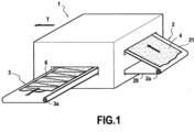
- the present invention relates to a device forming a spreader-lapper intended to coat a web of fibers, in particular non-woven, in particular at the outlet of a carding device, as well as to a method for controlling a spreader-lapper of this gender.
- a spreader-lapper arranged at the outlet of a carding device producing a web of non-woven fibers comprises a front belt bringing the web of fibers into the spreader-lapper to a mobile accumulator carriage following a movement back and forth, a rear belt bringing the accumulated web to a lapper carriage also movable following a back and forth movement and an exit apron, the accumulator carriage being arranged to return the fiber web towards the lapper trolley, and the latter being arranged to deposit the veil accumulated and returned by the accumulator trolley on the apron to obtain a tablecloth composed of layers which are at an angle, alternately in one direction and in the other, relative to the direction in length of the tablecloth.
- the characteristics of the web that we wish to obtain are adjusted in advance on the basis of the adjustments of the web entry speeds, speeds and strokes. moving carriages back and forth, and generally kinematic data of the constituents of the spreader spreader.
- the spreader-lapper devices known from the prior art have the disadvantage that defects in uniformity compared to the characteristics set in advance appearing here and there on the final tablecloth. This is especially the case when trying to increase production speed by using more powerful motors.
- the present invention aims at a lapper spreader making it possible to obtain the most uniform web possible in relation to these characteristics set in advance, and this preferably at the speed highest possible production.
- a spreader-lapper in particular arranged at the outlet of a carding device producing a web of fibers, in particular non-woven, comprising a front belt bringing the web of fibers into the spreader-lapper until to a mobile accumulator carriage following a back and forth movement; a rear belt bringing the accumulated veil to a mobile lapper carriage following a back and forth movement; and an outlet apron, the accumulator carriage being arranged to return the web of fiber towards the lapper carriage, and the latter being arranged to deposit the web accumulated and returned by the accumulator carriage on the apron at an angle, alternately in one direction and in the other, relative to the length direction of the web, the front and rear belts being driven by rollers respective front and rear drive motors driven by respective front and rear main motors, is characterized by anti-slip means intended to prevent relative sliding of at least one of the front and rear belts relative to its respective roller, especially rear, preferably both front and rear mats.
- the inventor of the present invention understood that the defects in uniformity with respect to the characteristics set in advance appearing on the web obtained at the outlet of the spreader-lapper are due to uncontrolled speed differentials between the front belt and the rear belt in particular in the path of the web between the accumulator carriage and the lapper carriage where the web is supported by the rear belt and capped by the front belt, as well as at speed differentials between the means bringing the card web and the front belt taking it up and speed differentials between the rear belt bringing the web into the lapper carriage and the speed of the latter depositing the web on the web being formed at the lapper outlet, each of these causes of fault is notably induced by sliding phenomena between the front belt or the rear belt and its control roller during the acceleration or deceleration phases of the belts occurring in particular at each reversal of the movement of the coating carriage.
- the accelerations and decelerations of the belts increase with the entry speed of the lapper, the defects induced by these sliding phenomena are accentuated with the production speed.
- the anti-slip means consist of at least one auxiliary drive roller associated with an auxiliary motor, which applies a complementary actuation force to the respective drive roller of said at least one of the front and rear belts, itself driven by its respective main engine.
- auxiliary drive roller in addition to the main drive roller, it facilitates the fine adjustment of the movement of the belt relative to the web, in particular by avoiding having to spend the effort necessary for the acceleration of any the length of the belt at a single control point and therefore increase the risk of slipping between the belt and its control roller during strong acceleration.
- the or each auxiliary drive roller is driven by a torque-controlled auxiliary motor.
- the or each main drive roller is driven by its speed-controlled main motor.
- the torque of the or each auxiliary motor is controlled as a function, in particular proportionally, of the acceleration of the lapper carriage and as a function of the layup cycles (forward acceleration, outward deceleration, return acceleration, return deceleration) so as to relieve the main motor in these acceleration and deceleration phases, thus reducing the effort to be transmitted between the main drive roller and the belt.
- the present invention also relates to a method for controlling a spreader-lapper comprising a front belt, an accumulator carriage, a rear belt, a lapper carriage and an exit apron, the speeds and movements of the different elements of the spreader-lapper being adjusted in advance to obtain a web having characteristics given in advance, the front belt being driven by a front drive roller driven by a front main motor and the rear belt being driven by a rear drive roller driven by a rear main motor, the accumulator and lapper carriages being mobile in a back-and-forth movement, is characterized by the step which consists of providing anti-slip means intended to cancel the slip between at least one of the front and rear belt and its respective drive roller, comprising at least one auxiliary drive roller driven by a torque-controlled auxiliary motor, and the or each main motor being speed-controlled.
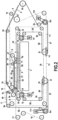
- the movements and/or displacements of the carriages 9 and 12 and the belts 5 and 2 are controlled by a central unit which controls their respective motors according to the kinematic data (positions, speeds, acceleration) desired for each, these settings define the parameters (in particular length, orientation of the bias folds and surface density) desired for the final tablecloth.
- the two belts 2 and 5 are endless belts which circulate in opposite directions to each other.
- the front belt 2 is guided along its circulation path by rollers 2a to 2n.
- the rear belt 5 is guided along its path by rollers 5b to 5n.
- the rollers are freely rotatable, except those connected to motor means, as described in the present application.
- the two belts are driven so as to have in the zone of mutual covering of the web (between the two carriages and up to the apron, in particular in the vertical passage 17 just before the site 11 of deposit on the tablecloth located on the apron 3 (driven by rollers, including in particular the roller 3a), equal speeds corresponding to the desired speed of feeding the web 4 to the deposition site 11.
- the rear belt 5 makes a 180° turn around the roller 5g after the zone 52 of mutual covering/pinching of the web by the two belts 2 and 5.
- the entrance belt 2 is diverted around a detour roller 2f.
- the lapper carriage moves back and forth in the horizontal direction in the figure.
- the belt 5 undergoes a variation in its length (substantially equal to twice the movement in one direction given from the cart 9). It is therefore appropriate to provide compensation for this variation, which is achieved by the fact that the rear belt 5 makes a 180° turn around a roller 5l carried by a compensating carriage 16 moving back and forth in synchronization with the movement of the carriage 9.
- regions 56 and 57 of the belt 5 shorten when regions 52, 53 and 59 of the belt 5 increase and vice versa.
- a toothed belt 76 is provided fixed at one end to the lapper carriage and at the other end to the carriage 16, the belt 76 meshing with a driving pulley 77 connected to a motor with two directions of operation, controlled in speed.
- an inextensible cable 78 connects the two other sides of the carriages 9 and 16.
- An identical arrangement is made to synchronize the movement of the accumulator carriage and the length of the input belt 2.
- the belt 2 makes a 180° turn around a roller 2l carried by a compensating carriage 14 moving back and forth in synchronization with the movement of the carriage 12.
- regions 26 and 27 of the belt 2 shorten when the regions 21, 22 and 23 of mat 2 increase and vice versa.
- a toothed belt 71 is provided fixed at one end to the accumulation carriage 12 and at the other end to the carriage 14, the belt 71 meshing with a driving pulley 72 connected to a motor with two directions of travel , ordered in speed.
- an inextensible cable 73 connects the two other sides of the carriages 12 and 14.
- Each of the belts 2, 5 passes over a respective motor roller 2i, 5i connected to a respective motor 74, 79 controlled in speed (serves motor, stepper or similar).
- Two return rollers, 2h, 2j and 5h, 5j are arranged on either side of the driving rollers 2i, 5i, in order to maximize the winding of the belt around its control roller and therefore its adhesion.
- the drive motors 74, 79 and the pulley motors 72, 77 are controlled (by the central unit not shown) to adapt them to the desired characteristics of the final product to be obtained (length, surface density, etc.) which depend in particular on the entry speed of the web and/or the stroke of the lapper carriage and/or the accelerations of the carriages, and/or others.
- a complementary motor 101 acts on the front belt 2. It operates a 2m drive roller, which is provided with an adherent coating and is preferably associated with a 2n detour roller to increase the winding of the carpet around the 2m roller.
- the motor roller 2i and the complementary motor roller 2m are placed relatively far from each other along the path of the belt to distribute the traction stresses as much as possible, particularly during acceleration phases.
- the complementary motor 101 is controlled in torque, in particular for each point of the coating cycle of the spreader-lapper.
- the torque of the complementary motor is controlled to avoid relative sliding between the front belt 2 and the motor roller 2i.
- a complementary motor 111 acts on the rear belt 5.
- 5m drive roller which is preferably lined with an adherent coating and associated with a 5n detour roller to increase the wrapping of the carpet around the 5m roller.
- the motor roller 5i and the complementary motor roller 5m are placed relatively far from each other along the path of the belt to distribute the traction stresses as much as possible, particularly during acceleration phases.
- the complementary motor 111 is controlled in torque, in particular for each point of the coating cycle of the spreader-lapper.
- the torque of the complementary motor is controlled to avoid relative sliding between the belt 5 and the motor roller 5i.
- the complementary motors make it possible to improve the behavior of the lapper spreader by canceling on the one hand the slipping of belts on their control rollers and on the other hand by limiting the tension variations in the belts during the phases of operation. acceleration and deceleration thanks to the two-point control of each belt. We thus combat the effects induced by carpet sliding on the tablecloth.
- a topping cycle can be as follows:
- the carriage 9 is then stopped while the carriage 12 moves at constant speed backwards to extend the regions 21 and 22 of the belt 2.
- the speed V74 of the main motor 74 of the belt 2 is zero because the regions 22 and 23 are immobile.
- the speed V12 of the carriage 12 is equal to half the entry speed of the web 4.
- the speed of the pinching region 52 of the belt 5 is zero because it is equal to the speed of the region 22 of the belt 2.
- the speed of the regions 58 and 59 is zero.
- Speed V111 of motor 111 is zero.
- the speed V79 of the motor 79 is twice the speed of the lapper carriage.
- a first phase P1 the lapper carriage accelerates backwards (towards the left at the figure 2 ), starting its forward movement.
- the speed of sections 52, 57, 58 and 59 remain zero while sections 53 to 56 undergo an acceleration equal to twice that of the lapper carriage 9 and its compensating carriage 16. Due to the acceleration of sections 55 and 56 as well as the compensating carriage 16 on the one hand and the need to maintain zero speed in sections 52, 57, 58 and 59, the application of a positive torque in the motor 111 yet at zero speed makes it possible to oppose tension induced by the acceleration of sections 58, 59 and 52 as well as by the rotational acceleration of rollers 5j, 5k and 5l that they induce.
- the positive torque applied by the motor 111 although at zero speed, thus makes it possible to relieve the motor 79 while reducing the voltage induced by these accelerations in the sections 58, 59 and 52.
- this phase P1 of the entire circuit of the belt before 2, only the rollers 2e, 2f and 2g undergo an acceleration induced by the acceleration of the carriage 9 which implies that a non-zero positive torque is applied by the motor 74 in order to keep the speed of the sections 22 and 23 zero.
- the torque applied by the motor 101 can then be zero or simply contribute to opposing the rotational friction of the roller 2l.
- This phase ends beyond the middle of the travel of the lapper carriage 9 and in particular beyond the last third of its travel to enter a phase P3 of deceleration of the carriage 9 until it stops at the end of the outward travel.
- the speed of sections 52, 57, 58 and 59 remain zero while sections 53 to 56 undergo a deceleration equal to twice that of the lapper carriage 9 and its compensating carriage 16.
- phase P4 the lapper carriage 9 accelerates towards the entrance (towards the right at the figure 2 ) beginning the return phase.
- the accumulator carriage which had remained at a constant speed during phases P1 to P3 begins its deceleration until it stops and then reverses.
- the motor 101 can in fact contribute to the deceleration of the rollers 2c and 2d induced by the deceleration of the accumulator carriage 12 but also to the acceleration of the rollers 2j to 2l induced by the need to accelerate the sail section 42 and therefore the section 22 at twice the acceleration of the lapper carriage 9 in order to maintain a speed of delivery of the veil at point 11 equal to the speed of the lapper carriage 9.
- sections 53 to 56 and rollers 5h to 5k are at zero speed.
- the section of belt 52 as well as the rollers 5m, 5n and 5b undergo an acceleration equal to 2 times that of the carriage 9 in order to feed it, while the rollers 5c to 5f, as well as 5l, undergo a combination between 2 times l acceleration of the lapper carriage 9 and deceleration of the accumulator carriage 12.
- the motor 79 will apply a positive torque opposing the movement of the section 53 induced by the accelerations of the rollers 5b to 5g.
- a positive torque on the motor 111 will assist the motor 79 by contributing in particular to the acceleration of the roller 5l and thus to the reduction of the tensions induced in the sections 58, 59, 52 and 53.
- This phase ends beyond the middle of the stroke of the lapper carriage 9 and in particular beyond the last third of its stroke to enter a phase P6 of deceleration of the carriage 9 until it stops at the end of the return stroke.
- the speed of sections 53, 55 and 56 remain zero while sections 52 and 57 to 59 undergo a deceleration equal to 2 times that of the lapper carriage 9 and its compensating carriage 16.
- the motor 101 can in fact contribute to the acceleration of the rollers 2c and 2d induced by the acceleration of the accumulator carriage 12 but also to the deceleration of the rollers 2j to 2l induced by the need to decelerate the sail section 42 and therefore the section 22 at twice the deceleration of the lapper carriage 9 in order to maintain a speed of delivery of the web at point 11 equal to the speed of the lapper carriage 9.
Landscapes
- Engineering & Computer Science (AREA)
- Textile Engineering (AREA)
- Treatment Of Fiber Materials (AREA)
- Advancing Webs (AREA)
Claims (5)
- Kreuzleger zum Bilden eines Vlieses (6), der insbesondere am Ausgang einer Krempelvorrichtung angeordnet ist, die einen Faserflor herstellt, insbesondere aus Faservlies, umfassend ein vorderes Transportband (2), das den Faserflor (4) in den Kreuzleger bis zu einem Speicherwagen (12) transportiert, der in eine hin- und hergehende Bewegung versetzt werden kann; ein hinteres Transportband (5), das den gesammelten Flor bis zu einem Legewagen (9) transportiert, der in eine hin- und hergehende Bewegung versetzt werden kann; und ein Auslauftisch (3), wobei der Speicherwagen (12) dazu eingerichtet ist, den Faserflor zum Legewagen (9) zurückzuschicken, und dieser Letztere dazu eingerichtet ist, den von dem Speicherwagen gesammelten und zurückgeschickten Flor auf dem Auslauftisch (3) abwechselnd in der einen Richtung und in der anderen, bezogen auf die Längenrichtung des Vlieses (6), schräg abzulegen, wobei das vordere (2) und das hintere Transportband (5) von einer vorderen bzw. einer hinteren Antriebswalze (2i, 5i) angetrieben werden, die von einem vorderen bzw. einem hinteren Hauptmotor (74, 79) angetrieben werden, gekennzeichnet durch Antirutschmittel, die dazu bestimmt sind, ein relatives Rutschen mindestens eines von dem vorderem (2) und dem hinteren Transportband (5) in Bezug auf seine jeweilige Antriebswalze (2i, 5i), insbesondere des hinteren, vorzugsweise beider Transportbänder (2, 5), des vorderen und des hinteren, zu verhindern, wobei die Antirutschmittel aus mindestens einer Hilfsantriebswalze (2m, 5m) bestehen, die einem Hilfsmotor (101, 111) zugeordnet ist, der eine komplementäre Betätigungskraft auf die jeweilige Antriebswalze des mindestens einen von dem vorderem und dem hinteren Transportband ausübt, die ihrerseits von ihrem jeweiligen Hauptmotor (74, 79) angetrieben wird, wobei die oder jede Hilfsantriebswalze (2m, 5m) von ihrem Hilfsmotor (101, 111) angetrieben wird, der drehmomentgesteuert ist, und wobei der oder jeder Hauptmotor (74, 79) drehzahlgesteuert ist.
- Kreuzleger nach Anspruch 1, dadurch gekennzeichnet, dass die Antirutschmittel derart ausgebildet sind, dass sie ein relatives Rutschen des vorderen und des hinteren Transportbandes (2, 5) in Bezug auf seine jeweilige Antriebswalze (2i, 5i) verhindern.
- Kreuzleger nach einem der Ansprüche 1 oder 2, dadurch gekennzeichnet, dass das Drehmoment des oder jedes Hilfsmotors (101, 111) in Abhängigkeit von, insbesondere proportional zu der Beschleunigung des Legewagens und in Abhängigkeit von den Legezyklen gesteuert wird, um den Hauptmotor (74, 79) in den Phasen von Beschleunigungen und Verzögerungen zu entlasten, wodurch die zwischen der jeweiligen Antriebswalze und dem Transportband zu übertragende Kraft verringert wird.
- Verfahren zur Steuerung eines Kreuzlegers, welcher ein vorderes Transportband (2), einen Speicherwagen (12), ein hinteres Transportband (5), einen Legewagen (9) und einen Auslauftisch (3) umfasst, wobei die Geschwindigkeiten und Bewegungen der verschiedenen Elemente des Kreuzlegers im Voraus eingestellt werden, um ein Vlies (6) mit vorgegebenen Eigenschaften zu erhalten, wobei das vordere Transportband (2) von einer vorderen Antriebswalze (2i) angetrieben wird, die von einem vorderen Hauptmotor (74) angetrieben wird, und das hintere Transportband (5) von einer hinteren Antriebswalze (5i) angetrieben wird, die von einem hinteren Hauptmotor (79) angetrieben wird, wobei der Speicherwagen und der Legewagen in eine hin- und hergehende Bewegung versetzt werden können, gekennzeichnet durch den Schritt, der darin besteht, Antirutschmittel vorzusehen, die dazu bestimmt sind, das Rutschen zwischen mindestens einem von dem vorderem (2) und dem hinteren Transportband (5) und seiner jeweiligen Antriebswalze (2i, 5i) zu verhindern, und mindestens eine Hilfsantriebswalze (2m, 5m) umfassen, die von einem Hilfsmotor (101, 111) angetrieben wird, der drehmomentgesteuert ist, und wobei der oder jeder Hauptmotor (74, 79) drehzahlgesteuert ist.
- Verfahren nach Anspruch 4, dadurch gekennzeichnet, dass die Antirutschmittel zwei Hilfswalzen (2m, 5m) umfassen, die jeweils von einem Hilfsmotor (101, 111) angetrieben werden, der drehmomentgesteuert ist, und wobei jeder Hauptmotor drehzahlgesteuert ist.
Applications Claiming Priority (1)
| Application Number | Priority Date | Filing Date | Title |
|---|---|---|---|
| FR1501818A FR3040398B1 (fr) | 2015-09-02 | 2015-09-02 | Dispositif formant etaleur -nappeur et procede pour commander un etaleur-nappeur de ce genre |
Publications (3)
| Publication Number | Publication Date |
|---|---|
| EP3141640A1 EP3141640A1 (de) | 2017-03-15 |
| EP3141640C0 EP3141640C0 (de) | 2024-04-17 |
| EP3141640B1 true EP3141640B1 (de) | 2024-04-17 |
Family
ID=54356380
Family Applications (1)
| Application Number | Title | Priority Date | Filing Date |
|---|---|---|---|
| EP16186076.2A Active EP3141640B1 (de) | 2015-09-02 | 2016-08-29 | Kreuzleger und verfahren zur steuerung eines kreuzlegers |
Country Status (2)
| Country | Link |
|---|---|
| EP (1) | EP3141640B1 (de) |
| FR (2) | FR3040398B1 (de) |
Families Citing this family (10)
| Publication number | Priority date | Publication date | Assignee | Title |
|---|---|---|---|---|
| FR3063741A1 (fr) * | 2017-03-09 | 2018-09-14 | Andritz Asselin Thibeau | Etaleur nappeur |
| CN107034588B (zh) * | 2017-06-08 | 2022-11-01 | 常熟市伟成非织造成套设备有限公司 | 具有压棉功能的铺网小车 |
| CN107043967B (zh) * | 2017-06-08 | 2022-10-28 | 常熟市伟成非织造成套设备有限公司 | 具有压棉功能的铺网机 |
| CN109825953A (zh) * | 2019-03-14 | 2019-05-31 | 常熟市弘毅无纺机械有限公司 | 一种交叉铺网机 |
| CN110760995B (zh) * | 2019-11-13 | 2024-06-21 | 常熟万龙机械有限公司 | 一种铺网机 |
| CN110670244A (zh) * | 2019-11-20 | 2020-01-10 | 常熟市振泰无纺机械有限公司 | 高速铺网机 |
| CN115897063B (zh) * | 2022-09-02 | 2026-02-06 | 西门子(中国)有限公司 | 铺网机的铺网控制方法、装置和计算机可读介质 |
| CN116463787A (zh) * | 2023-04-23 | 2023-07-21 | 江苏迎阳无纺机械有限公司 | 与铺网机配套的无纺织纤维棉网补偿装置 |
| CN117230574B (zh) * | 2023-08-10 | 2026-04-10 | 福建建壹真空科技有限公司 | 一种玻璃纤维薄毡高速铺网控制方法和控制系统 |
| CN117947579A (zh) * | 2024-03-27 | 2024-04-30 | 厦门当盛新材料有限公司 | 多单元组合式高速纺丝铺网机、铺网方法及闪蒸无纺布 |
Citations (1)
| Publication number | Priority date | Publication date | Assignee | Title |
|---|---|---|---|---|
| EP1612306A1 (de) * | 2004-07-01 | 2006-01-04 | Oskar Dilo Maschinenfabrik KG | Vliesleger |
Family Cites Families (7)
| Publication number | Priority date | Publication date | Assignee | Title |
|---|---|---|---|---|
| DE525809C (de) * | 1931-05-29 | Mix & Genest Akt Ges | Mehrfacher Antrieb fuer Foerderbaender | |
| FR2045652A2 (fr) * | 1969-06-16 | 1971-03-05 | Forderanlagen Bautzen | Dispositif de commande, en particulier pour l'entraînement multiple de transporteurs circulaires pour l'obtention d'un transfert de charge uniforme des dispositifs d'entraînement individuels. |
| FR2677046B1 (fr) * | 1991-06-03 | 1995-01-13 | Asselin Ets | Etaleur-nappeur. |
| US5452791A (en) * | 1994-07-18 | 1995-09-26 | Cominco Engineering Services Ltd. | Dual drive for belt conveyor |
| FR2770855B1 (fr) * | 1997-11-07 | 2000-01-28 | Asselin | Procede et dispositif pour produire une nappe textile |
| FR2791364B1 (fr) * | 1999-03-23 | 2001-06-08 | Asselin | Etaleur-nappeur |
| DE502006000950D1 (de) * | 2006-02-01 | 2008-07-31 | Dilo Kg Maschf Oskar | Vorrichtung zum Legen eines Vlieses |
-
2015
- 2015-09-02 FR FR1501818A patent/FR3040398B1/fr active Active
- 2015-10-28 FR FR1502271A patent/FR3040400B1/fr active Active
-
2016
- 2016-08-29 EP EP16186076.2A patent/EP3141640B1/de active Active
Patent Citations (1)
| Publication number | Priority date | Publication date | Assignee | Title |
|---|---|---|---|---|
| EP1612306A1 (de) * | 2004-07-01 | 2006-01-04 | Oskar Dilo Maschinenfabrik KG | Vliesleger |
Also Published As
| Publication number | Publication date |
|---|---|
| EP3141640C0 (de) | 2024-04-17 |
| FR3040400B1 (fr) | 2018-06-15 |
| EP3141640A1 (de) | 2017-03-15 |
| FR3040398A1 (fr) | 2017-03-03 |
| FR3040400A1 (fr) | 2017-03-03 |
| FR3040398B1 (fr) | 2018-07-13 |
Similar Documents
| Publication | Publication Date | Title |
|---|---|---|
| EP3141640A1 (de) | Kreuzleger und verfahren zur steuerung eines kreuzlegers | |
| EP1036227B1 (de) | Verfahren und vorrichtung zur herstellung eines textilen vlieses | |
| EP3138945B1 (de) | Vorrichtung, die einen kreuzleger mit zahnriemen bildet | |
| EP1936016A2 (de) | Verfahren zur Einstellung der lokalen Eigenschaften eines Vliesstoffs und entsprechende Anlage | |
| EP0517563B2 (de) | Vliesbandleger | |
| EP0522893B1 (de) | Vliesbandleger | |
| EP3545122B1 (de) | Vorrichtung zum strecken einer bahn zwischen einer kardiervorrichtung und einem kreuzleger | |
| EP1009871B1 (de) | Verfahren und vorrichtung zur herstellung eines vlieses und ein kontinuierliches profiltextilerzeugnis | |
| EP1897979A2 (de) | Verfahren und System zur Produktion eines mehrschichtigen Vlieses, insbesondere mittels eines Vlieslegers | |
| EP0530100B1 (de) | Vliesablegeverfahren, Vliesablegeerzeugnis und Vliesbandleger zur Durchführung des Verfahrens | |
| WO2024023049A1 (fr) | Dispositif tampon pour adapter la vitesse de sortie d'une nappe d'un etaleur nappeur a la vitesse d'entree d'un dispositif de traitement de la nappe en aval de l'etaleur nappeur | |
| EP2128314B9 (de) | Puffervorrichtung und -system sowie Produktionssystem einer Vliesstoffbahn | |
| EP3575455B1 (de) | System zur bildung eines vlieses | |
| FR2553102A1 (fr) | Etaleur-nappeur | |
| EP3592887B1 (de) | Kreuzleger | |
| BE1009329A6 (fr) | Procede et dispositif de faconnage en panneaux d'une bande de matelas de fibres. | |
| FR2894600A1 (fr) | Transport d'une bande de non-tisse au moyen d'une bande de transport avec portion ascendante et/ou a vitesse variable |
Legal Events
| Date | Code | Title | Description |
|---|---|---|---|
| PUAI | Public reference made under article 153(3) epc to a published international application that has entered the european phase |
Free format text: ORIGINAL CODE: 0009012 |
|
| STAA | Information on the status of an ep patent application or granted ep patent |
Free format text: STATUS: THE APPLICATION HAS BEEN PUBLISHED |
|
| AK | Designated contracting states |
Kind code of ref document: A1 Designated state(s): AL AT BE BG CH CY CZ DE DK EE ES FI FR GB GR HR HU IE IS IT LI LT LU LV MC MK MT NL NO PL PT RO RS SE SI SK SM TR |
|
| AX | Request for extension of the european patent |
Extension state: BA ME |
|
| STAA | Information on the status of an ep patent application or granted ep patent |
Free format text: STATUS: REQUEST FOR EXAMINATION WAS MADE |
|
| 17P | Request for examination filed |
Effective date: 20170915 |
|
| RBV | Designated contracting states (corrected) |
Designated state(s): AL AT BE BG CH CY CZ DE DK EE ES FI FR GB GR HR HU IE IS IT LI LT LU LV MC MK MT NL NO PL PT RO RS SE SI SK SM TR |
|
| STAA | Information on the status of an ep patent application or granted ep patent |
Free format text: STATUS: EXAMINATION IS IN PROGRESS |
|
| 17Q | First examination report despatched |
Effective date: 20210215 |
|
| GRAP | Despatch of communication of intention to grant a patent |
Free format text: ORIGINAL CODE: EPIDOSNIGR1 |
|
| STAA | Information on the status of an ep patent application or granted ep patent |
Free format text: STATUS: GRANT OF PATENT IS INTENDED |
|
| INTG | Intention to grant announced |
Effective date: 20231110 |
|
| GRAS | Grant fee paid |
Free format text: ORIGINAL CODE: EPIDOSNIGR3 |
|
| GRAA | (expected) grant |
Free format text: ORIGINAL CODE: 0009210 |
|
| STAA | Information on the status of an ep patent application or granted ep patent |
Free format text: STATUS: THE PATENT HAS BEEN GRANTED |
|
| AK | Designated contracting states |
Kind code of ref document: B1 Designated state(s): AL AT BE BG CH CY CZ DE DK EE ES FI FR GB GR HR HU IE IS IT LI LT LU LV MC MK MT NL NO PL PT RO RS SE SI SK SM TR |
|
| REG | Reference to a national code |
Ref country code: GB Ref legal event code: FG4D Free format text: NOT ENGLISH |
|
| REG | Reference to a national code |
Ref country code: CH Ref legal event code: EP |
|
| REG | Reference to a national code |
Ref country code: DE Ref legal event code: R096 Ref document number: 602016086948 Country of ref document: DE |
|
| REG | Reference to a national code |
Ref country code: IE Ref legal event code: FG4D Free format text: LANGUAGE OF EP DOCUMENT: FRENCH |
|
| U01 | Request for unitary effect filed |
Effective date: 20240513 |
|
| U07 | Unitary effect registered |
Designated state(s): AT BE BG DE DK EE FI FR IT LT LU LV MT NL PT SE SI Effective date: 20240524 |
|
| U20 | Renewal fee for the european patent with unitary effect paid |
Year of fee payment: 9 Effective date: 20240827 |
|
| PG25 | Lapsed in a contracting state [announced via postgrant information from national office to epo] |
Ref country code: IS Free format text: LAPSE BECAUSE OF FAILURE TO SUBMIT A TRANSLATION OF THE DESCRIPTION OR TO PAY THE FEE WITHIN THE PRESCRIBED TIME-LIMIT Effective date: 20240817 |
|
| PG25 | Lapsed in a contracting state [announced via postgrant information from national office to epo] |
Ref country code: HR Free format text: LAPSE BECAUSE OF FAILURE TO SUBMIT A TRANSLATION OF THE DESCRIPTION OR TO PAY THE FEE WITHIN THE PRESCRIBED TIME-LIMIT Effective date: 20240417 |
|
| PG25 | Lapsed in a contracting state [announced via postgrant information from national office to epo] |
Ref country code: GR Free format text: LAPSE BECAUSE OF FAILURE TO SUBMIT A TRANSLATION OF THE DESCRIPTION OR TO PAY THE FEE WITHIN THE PRESCRIBED TIME-LIMIT Effective date: 20240718 |
|
| PG25 | Lapsed in a contracting state [announced via postgrant information from national office to epo] |
Ref country code: ES Free format text: LAPSE BECAUSE OF FAILURE TO SUBMIT A TRANSLATION OF THE DESCRIPTION OR TO PAY THE FEE WITHIN THE PRESCRIBED TIME-LIMIT Effective date: 20240417 |
|
| PG25 | Lapsed in a contracting state [announced via postgrant information from national office to epo] |
Ref country code: PL Free format text: LAPSE BECAUSE OF FAILURE TO SUBMIT A TRANSLATION OF THE DESCRIPTION OR TO PAY THE FEE WITHIN THE PRESCRIBED TIME-LIMIT Effective date: 20240417 |
|
| PG25 | Lapsed in a contracting state [announced via postgrant information from national office to epo] |
Ref country code: PL Free format text: LAPSE BECAUSE OF FAILURE TO SUBMIT A TRANSLATION OF THE DESCRIPTION OR TO PAY THE FEE WITHIN THE PRESCRIBED TIME-LIMIT Effective date: 20240417 Ref country code: NO Free format text: LAPSE BECAUSE OF FAILURE TO SUBMIT A TRANSLATION OF THE DESCRIPTION OR TO PAY THE FEE WITHIN THE PRESCRIBED TIME-LIMIT Effective date: 20240717 Ref country code: IS Free format text: LAPSE BECAUSE OF FAILURE TO SUBMIT A TRANSLATION OF THE DESCRIPTION OR TO PAY THE FEE WITHIN THE PRESCRIBED TIME-LIMIT Effective date: 20240817 Ref country code: HR Free format text: LAPSE BECAUSE OF FAILURE TO SUBMIT A TRANSLATION OF THE DESCRIPTION OR TO PAY THE FEE WITHIN THE PRESCRIBED TIME-LIMIT Effective date: 20240417 Ref country code: GR Free format text: LAPSE BECAUSE OF FAILURE TO SUBMIT A TRANSLATION OF THE DESCRIPTION OR TO PAY THE FEE WITHIN THE PRESCRIBED TIME-LIMIT Effective date: 20240718 Ref country code: ES Free format text: LAPSE BECAUSE OF FAILURE TO SUBMIT A TRANSLATION OF THE DESCRIPTION OR TO PAY THE FEE WITHIN THE PRESCRIBED TIME-LIMIT Effective date: 20240417 Ref country code: RS Free format text: LAPSE BECAUSE OF FAILURE TO SUBMIT A TRANSLATION OF THE DESCRIPTION OR TO PAY THE FEE WITHIN THE PRESCRIBED TIME-LIMIT Effective date: 20240717 |
|
| REG | Reference to a national code |
Ref country code: DE Ref legal event code: R097 Ref document number: 602016086948 Country of ref document: DE |
|
| PG25 | Lapsed in a contracting state [announced via postgrant information from national office to epo] |
Ref country code: CZ Free format text: LAPSE BECAUSE OF FAILURE TO SUBMIT A TRANSLATION OF THE DESCRIPTION OR TO PAY THE FEE WITHIN THE PRESCRIBED TIME-LIMIT Effective date: 20240417 |
|
| PG25 | Lapsed in a contracting state [announced via postgrant information from national office to epo] |
Ref country code: SK Free format text: LAPSE BECAUSE OF FAILURE TO SUBMIT A TRANSLATION OF THE DESCRIPTION OR TO PAY THE FEE WITHIN THE PRESCRIBED TIME-LIMIT Effective date: 20240417 Ref country code: RO Free format text: LAPSE BECAUSE OF FAILURE TO SUBMIT A TRANSLATION OF THE DESCRIPTION OR TO PAY THE FEE WITHIN THE PRESCRIBED TIME-LIMIT Effective date: 20240417 |
|
| PG25 | Lapsed in a contracting state [announced via postgrant information from national office to epo] |
Ref country code: SM Free format text: LAPSE BECAUSE OF FAILURE TO SUBMIT A TRANSLATION OF THE DESCRIPTION OR TO PAY THE FEE WITHIN THE PRESCRIBED TIME-LIMIT Effective date: 20240417 |
|
| PG25 | Lapsed in a contracting state [announced via postgrant information from national office to epo] |
Ref country code: SM Free format text: LAPSE BECAUSE OF FAILURE TO SUBMIT A TRANSLATION OF THE DESCRIPTION OR TO PAY THE FEE WITHIN THE PRESCRIBED TIME-LIMIT Effective date: 20240417 Ref country code: SK Free format text: LAPSE BECAUSE OF FAILURE TO SUBMIT A TRANSLATION OF THE DESCRIPTION OR TO PAY THE FEE WITHIN THE PRESCRIBED TIME-LIMIT Effective date: 20240417 Ref country code: RO Free format text: LAPSE BECAUSE OF FAILURE TO SUBMIT A TRANSLATION OF THE DESCRIPTION OR TO PAY THE FEE WITHIN THE PRESCRIBED TIME-LIMIT Effective date: 20240417 Ref country code: CZ Free format text: LAPSE BECAUSE OF FAILURE TO SUBMIT A TRANSLATION OF THE DESCRIPTION OR TO PAY THE FEE WITHIN THE PRESCRIBED TIME-LIMIT Effective date: 20240417 |
|
| PLBE | No opposition filed within time limit |
Free format text: ORIGINAL CODE: 0009261 |
|
| STAA | Information on the status of an ep patent application or granted ep patent |
Free format text: STATUS: NO OPPOSITION FILED WITHIN TIME LIMIT |
|
| 26N | No opposition filed |
Effective date: 20250120 |
|
| REG | Reference to a national code |
Ref country code: CH Ref legal event code: PL |
|
| GBPC | Gb: european patent ceased through non-payment of renewal fee |
Effective date: 20240829 |
|
| PG25 | Lapsed in a contracting state [announced via postgrant information from national office to epo] |
Ref country code: CH Free format text: LAPSE BECAUSE OF NON-PAYMENT OF DUE FEES Effective date: 20240831 Ref country code: MC Free format text: LAPSE BECAUSE OF FAILURE TO SUBMIT A TRANSLATION OF THE DESCRIPTION OR TO PAY THE FEE WITHIN THE PRESCRIBED TIME-LIMIT Effective date: 20240417 |
|
| PG25 | Lapsed in a contracting state [announced via postgrant information from national office to epo] |
Ref country code: GB Free format text: LAPSE BECAUSE OF NON-PAYMENT OF DUE FEES Effective date: 20240829 |
|
| PG25 | Lapsed in a contracting state [announced via postgrant information from national office to epo] |
Ref country code: IE Free format text: LAPSE BECAUSE OF NON-PAYMENT OF DUE FEES Effective date: 20240829 |
|
| U20 | Renewal fee for the european patent with unitary effect paid |
Year of fee payment: 10 Effective date: 20250827 |
|
| PGFP | Annual fee paid to national office [announced via postgrant information from national office to epo] |
Ref country code: TR Payment date: 20250825 Year of fee payment: 10 |
|
| PG25 | Lapsed in a contracting state [announced via postgrant information from national office to epo] |
Ref country code: CY Free format text: LAPSE BECAUSE OF FAILURE TO SUBMIT A TRANSLATION OF THE DESCRIPTION OR TO PAY THE FEE WITHIN THE PRESCRIBED TIME-LIMIT; INVALID AB INITIO Effective date: 20160829 |
|
| PG25 | Lapsed in a contracting state [announced via postgrant information from national office to epo] |
Ref country code: HU Free format text: LAPSE BECAUSE OF FAILURE TO SUBMIT A TRANSLATION OF THE DESCRIPTION OR TO PAY THE FEE WITHIN THE PRESCRIBED TIME-LIMIT; INVALID AB INITIO Effective date: 20160829 |
|
| U1K | Transfer of rights of the unitary patent after the registration of the unitary effect |
Owner name: ANDRITZ FRANCE SAS; FR |