EP3147035A1 - Lackierverfahren und lackieranlage - Google Patents
Lackierverfahren und lackieranlage Download PDFInfo
- Publication number
- EP3147035A1 EP3147035A1 EP15795732.5A EP15795732A EP3147035A1 EP 3147035 A1 EP3147035 A1 EP 3147035A1 EP 15795732 A EP15795732 A EP 15795732A EP 3147035 A1 EP3147035 A1 EP 3147035A1
- Authority
- EP
- European Patent Office
- Prior art keywords
- painting
- holder
- robot
- subsequent
- area
- Prior art date
- Legal status (The legal status is an assumption and is not a legal conclusion. Google has not performed a legal analysis and makes no representation as to the accuracy of the status listed.)
- Granted
Links
Images




Classifications
-
- B—PERFORMING OPERATIONS; TRANSPORTING
- B05—SPRAYING OR ATOMISING IN GENERAL; APPLYING FLUENT MATERIALS TO SURFACES, IN GENERAL
- B05B—SPRAYING APPARATUS; ATOMISING APPARATUS; NOZZLES
- B05B13/00—Machines or plants for applying liquids or other fluent materials to surfaces of objects or other work by spraying, not covered by groups B05B1/00 - B05B11/00
- B05B13/02—Means for supporting work; Arrangement or mounting of spray heads; Adaptation or arrangement of means for feeding work
- B05B13/04—Means for supporting work; Arrangement or mounting of spray heads; Adaptation or arrangement of means for feeding work the spray heads being moved during spraying operation
- B05B13/0431—Means for supporting work; Arrangement or mounting of spray heads; Adaptation or arrangement of means for feeding work the spray heads being moved during spraying operation with spray heads moved by robots or articulated arms, e.g. for applying liquid or other fluent material to three-dimensional [3D] surfaces
-
- B—PERFORMING OPERATIONS; TRANSPORTING
- B05—SPRAYING OR ATOMISING IN GENERAL; APPLYING FLUENT MATERIALS TO SURFACES, IN GENERAL
- B05B—SPRAYING APPARATUS; ATOMISING APPARATUS; NOZZLES
- B05B12/00—Arrangements for controlling delivery; Arrangements for controlling the spray area
- B05B12/004—Arrangements for controlling delivery; Arrangements for controlling the spray area comprising sensors for monitoring the delivery, e.g. by displaying the sensed value or generating an alarm
- B05B12/006—Pressure or flow rate sensors
-
- B—PERFORMING OPERATIONS; TRANSPORTING
- B05—SPRAYING OR ATOMISING IN GENERAL; APPLYING FLUENT MATERIALS TO SURFACES, IN GENERAL
- B05B—SPRAYING APPARATUS; ATOMISING APPARATUS; NOZZLES
- B05B13/00—Machines or plants for applying liquids or other fluent materials to surfaces of objects or other work by spraying, not covered by groups B05B1/00 - B05B11/00
- B05B13/02—Means for supporting work; Arrangement or mounting of spray heads; Adaptation or arrangement of means for feeding work
- B05B13/0221—Means for supporting work; Arrangement or mounting of spray heads; Adaptation or arrangement of means for feeding work characterised by the means for moving or conveying the objects or other work, e.g. conveyor belts
-
- B—PERFORMING OPERATIONS; TRANSPORTING
- B05—SPRAYING OR ATOMISING IN GENERAL; APPLYING FLUENT MATERIALS TO SURFACES, IN GENERAL
- B05B—SPRAYING APPARATUS; ATOMISING APPARATUS; NOZZLES
- B05B13/00—Machines or plants for applying liquids or other fluent materials to surfaces of objects or other work by spraying, not covered by groups B05B1/00 - B05B11/00
- B05B13/02—Means for supporting work; Arrangement or mounting of spray heads; Adaptation or arrangement of means for feeding work
- B05B13/04—Means for supporting work; Arrangement or mounting of spray heads; Adaptation or arrangement of means for feeding work the spray heads being moved during spraying operation
- B05B13/0431—Means for supporting work; Arrangement or mounting of spray heads; Adaptation or arrangement of means for feeding work the spray heads being moved during spraying operation with spray heads moved by robots or articulated arms, e.g. for applying liquid or other fluent material to three-dimensional [3D] surfaces
- B05B13/0433—Means for supporting work; Arrangement or mounting of spray heads; Adaptation or arrangement of means for feeding work the spray heads being moved during spraying operation with spray heads moved by robots or articulated arms, e.g. for applying liquid or other fluent material to three-dimensional [3D] surfaces the work being vehicle components, e.g. vehicle bodies
-
- B—PERFORMING OPERATIONS; TRANSPORTING
- B05—SPRAYING OR ATOMISING IN GENERAL; APPLYING FLUENT MATERIALS TO SURFACES, IN GENERAL
- B05B—SPRAYING APPARATUS; ATOMISING APPARATUS; NOZZLES
- B05B14/00—Arrangements for collecting, re-using or eliminating excess spraying material
- B05B14/40—Arrangements for collecting, re-using or eliminating excess spraying material for use in spray booths
- B05B14/41—Arrangements for collecting, re-using or eliminating excess spraying material for use in spray booths by cleaning the walls of the booth
- B05B14/412—Arrangements for collecting, re-using or eliminating excess spraying material for use in spray booths by cleaning the walls of the booth wherein the walls of the booth is perforated or porous walls and the walls are cleaned of or prevented from being contacted with excess material by a flow of fluid, e.g. air or water, directed into the booth
-
- B—PERFORMING OPERATIONS; TRANSPORTING
- B05—SPRAYING OR ATOMISING IN GENERAL; APPLYING FLUENT MATERIALS TO SURFACES, IN GENERAL
- B05B—SPRAYING APPARATUS; ATOMISING APPARATUS; NOZZLES
- B05B15/00—Details of spraying plant or spraying apparatus not otherwise provided for; Accessories
- B05B15/70—Arrangements for moving spray heads automatically to or from the working position
- B05B15/72—Arrangements for moving spray heads automatically to or from the working position using hydraulic or pneumatic means
-
- B—PERFORMING OPERATIONS; TRANSPORTING
- B05—SPRAYING OR ATOMISING IN GENERAL; APPLYING FLUENT MATERIALS TO SURFACES, IN GENERAL
- B05B—SPRAYING APPARATUS; ATOMISING APPARATUS; NOZZLES
- B05B16/00—Spray booths
-
- B—PERFORMING OPERATIONS; TRANSPORTING
- B05—SPRAYING OR ATOMISING IN GENERAL; APPLYING FLUENT MATERIALS TO SURFACES, IN GENERAL
- B05B—SPRAYING APPARATUS; ATOMISING APPARATUS; NOZZLES
- B05B16/00—Spray booths
- B05B16/20—Arrangements for spraying in combination with other operations, e.g. drying; Arrangements enabling a combination of spraying operations
-
- B—PERFORMING OPERATIONS; TRANSPORTING
- B05—SPRAYING OR ATOMISING IN GENERAL; APPLYING FLUENT MATERIALS TO SURFACES, IN GENERAL
- B05D—PROCESSES FOR APPLYING FLUENT MATERIALS TO SURFACES, IN GENERAL
- B05D1/00—Processes for applying liquids or other fluent materials
- B05D1/02—Processes for applying liquids or other fluent materials performed by spraying
-
- B—PERFORMING OPERATIONS; TRANSPORTING
- B25—HAND TOOLS; PORTABLE POWER-DRIVEN TOOLS; MANIPULATORS
- B25J—MANIPULATORS; CHAMBERS PROVIDED WITH MANIPULATION DEVICES
- B25J11/00—Manipulators not otherwise provided for
- B25J11/0075—Manipulators for painting or coating
-
- B—PERFORMING OPERATIONS; TRANSPORTING
- B25—HAND TOOLS; PORTABLE POWER-DRIVEN TOOLS; MANIPULATORS
- B25J—MANIPULATORS; CHAMBERS PROVIDED WITH MANIPULATION DEVICES
- B25J15/00—Gripping heads and other end effectors
- B25J15/0052—Gripping heads and other end effectors multiple gripper units or multiple end effectors
-
- B—PERFORMING OPERATIONS; TRANSPORTING
- B25—HAND TOOLS; PORTABLE POWER-DRIVEN TOOLS; MANIPULATORS
- B25J—MANIPULATORS; CHAMBERS PROVIDED WITH MANIPULATION DEVICES
- B25J15/00—Gripping heads and other end effectors
- B25J15/04—Gripping heads and other end effectors with provision for the remote detachment or exchange of the head or parts thereof
- B25J15/0408—Connections means
- B25J15/0441—Connections means having vacuum or magnetic means
-
- B—PERFORMING OPERATIONS; TRANSPORTING
- B25—HAND TOOLS; PORTABLE POWER-DRIVEN TOOLS; MANIPULATORS
- B25J—MANIPULATORS; CHAMBERS PROVIDED WITH MANIPULATION DEVICES
- B25J15/00—Gripping heads and other end effectors
- B25J15/06—Gripping heads and other end effectors with vacuum or magnetic holding means
- B25J15/0616—Gripping heads and other end effectors with vacuum or magnetic holding means with vacuum
-
- B—PERFORMING OPERATIONS; TRANSPORTING
- B25—HAND TOOLS; PORTABLE POWER-DRIVEN TOOLS; MANIPULATORS
- B25J—MANIPULATORS; CHAMBERS PROVIDED WITH MANIPULATION DEVICES
- B25J9/00—Program-controlled manipulators
- B25J9/0084—Program-controlled manipulators comprising a plurality of manipulators
-
- B—PERFORMING OPERATIONS; TRANSPORTING
- B05—SPRAYING OR ATOMISING IN GENERAL; APPLYING FLUENT MATERIALS TO SURFACES, IN GENERAL
- B05B—SPRAYING APPARATUS; ATOMISING APPARATUS; NOZZLES
- B05B12/00—Arrangements for controlling delivery; Arrangements for controlling the spray area
- B05B12/08—Arrangements for controlling delivery; Arrangements for controlling the spray area responsive to condition of liquid or other fluent material to be discharged, of ambient medium or of target ; responsive to condition of spray devices or of supply means, e.g. pipes, pumps or their drive means
- B05B12/12—Arrangements for controlling delivery; Arrangements for controlling the spray area responsive to condition of liquid or other fluent material to be discharged, of ambient medium or of target ; responsive to condition of spray devices or of supply means, e.g. pipes, pumps or their drive means responsive to conditions of ambient medium or target, e.g. humidity, temperature position or movement of the target relative to the spray apparatus
- B05B12/122—Arrangements for controlling delivery; Arrangements for controlling the spray area responsive to condition of liquid or other fluent material to be discharged, of ambient medium or of target ; responsive to condition of spray devices or of supply means, e.g. pipes, pumps or their drive means responsive to conditions of ambient medium or target, e.g. humidity, temperature position or movement of the target relative to the spray apparatus responsive to presence or shape of target
-
- B—PERFORMING OPERATIONS; TRANSPORTING
- B05—SPRAYING OR ATOMISING IN GENERAL; APPLYING FLUENT MATERIALS TO SURFACES, IN GENERAL
- B05B—SPRAYING APPARATUS; ATOMISING APPARATUS; NOZZLES
- B05B14/00—Arrangements for collecting, re-using or eliminating excess spraying material
- B05B14/40—Arrangements for collecting, re-using or eliminating excess spraying material for use in spray booths
- B05B14/43—Arrangements for collecting, re-using or eliminating excess spraying material for use in spray booths by filtering the air charged with excess material
Definitions
- This invention relates to a painting method and a painting facility for implementing the painting method.
- an object to be painted (hereinafter “painting object”) is connected via a holder to an arm leading end portion of a painting robot. Then, while the painting object is being displaced relative to a spraying means by an action of the painting robot, the painting object is painted by paint spraying from the spraying means.
- Patent Document 1 identified below discloses the following technical matters (see in particular, its Figs. 14-17 ).
- a plurality of painting areas (“painting zones”) are disposed side by side in a row.
- a downwardly oriented spraying means and a painting robot for changing a position and a posture of the painting object (a bumper of an automobile in this case) relative to paint spraying from the spraying means.
- Patent Document 1 discloses following technical matters also.
- Patent Document 1 Japanese Unexamined Patent Application Publication No. 2005-103446
- the painting object is fixed to the painting robot via the holder (jig), the document is silent even about the specific manner of handling of such holder.
- Patent Document 1 suffer the problem of inability yet of realizing a painting operation in the manner of receiving/transferring a painting object between painting areas with using a painting robot configured to displace the painting object relative to the spraying means.
- a principal object of the present invention is to overcome the above problem by adopting a reasonable manner of receipt and transfer, regarding the receipt and transfer of the painting object between painting areas.
- a first characterizing feature of the present invention relates to a painting method, and according to the feature, a painting method in which a painting object is connected via a holder to an arm leading end portion of a painting robot and the painting object is painted by paint spraying from a spraying means while displacing the painting object relative to the spraying means by an action of the painting robot; wherein in a preceding painting area, a preceding painting is effected on the painting object by paint spraying from a preceding spraying means while displacing the painting object relative to the preceding spraying means by an action of a preceding painting robot, with keeping the painting object connected via the holder to an arm leading end portion of the preceding painting robot; wherein in a subsequent painting area subsequently to the preceding painting in the preceding painting area, a subsequent painting is effected on the painting object by paint spraying from a subsequent spraying means while displacing the painting object relative to the subsequent spraying means by an action of a subsequent painting robot, with keeping the painting object connected via the holder
- the painting object is painted by paint spraying from the spraying means while displacing the painting object relative to the spraying means by an action of the painting robot.
- paint coating effect of the sprayed paint to the painting object can be enhanced. Further, adherence of excess sprayed paint to e.g. chamber wall of the painting area can be effectively reduced also.
- the painting object when the painting object is to be transferred to the subsequent painting robot for subsequent painting, by an action of the preceding painting robot, the painting object, together with the holder, is caused to be transferred to the transfer section adjacent the two painting areas.
- the relative positional relation of the painting object relative to the arm leading end portion of the painting robot and the connection posture of the painting object relative to the arm leading end portion of the painting robot can be maintained same in the preceding painting and the subsequent painting.
- the respective motions of the preceding painting robot and the subsequent painting robot can be simple. Further, while the configuration of the holder is made simple, the painting object can be painted with high accuracy in the preceding painting and the subsequent painting respectively.
- the present invention is applicable also to a case of disposing three or more painting areas side by side, in a mode such that a painting area which becomes a subsequent painting area relative to a foregoing painting area constitutes a "preceding painting area" relative to a next painting area.
- a second characterizing feature of the present invention relates to a painting facility for implementing the painting method according to the first characterizing feature, and according to this feature, the painting facility comprises:
- the relative positional relation of the painting object relative to the arm leading end portion of the painting robot and the connection posture of the painting object relative to the arm leading end portion of the painting robot can be maintained same in the preceding painting and the subsequent painting.
- the respective motions of the preceding painting robot and the subsequent painting robot can be simple. Further, while the configuration of the holder is made simple, the painting object can be painted with high accuracy in the preceding painting and the subsequent painting respectively.
- the controlling means automatically executes release of connection between the arm leading end portion of the preceding painting robot and the holder after completion of the preceding painting and executes subsequent connection between the arm leading end portion of the subsequent painting robot and the holder.
- the reception/transfer of the painting object between the preceding painting robot and the subsequent painting robot can be effected in an even more smooth and reliable manner.
- a third characterizing feature of the present invention relates to the painting facility having the second characterizing feature, according to the feature, in the execution of the automatic action of the preceding painting robot and the subsequent painting robot in accordance with the preset operational program, the controlling means displaces the painting object relative to the preceding spraying means and the subsequent painting means, with varying the posture of the painting object in such a manner to maintain a painting progress face at each timing of the painting object perpendicular to a paint spraying direction from the preceding spraying means and the subsequent painting means.
- the coating efficiency of paint spraying to the painting object can be maintained even higher. Also, the coating quality of the painting object can be further improved also. Moreover, adherence of excess sprayed paint to e.g. a chamber wall of a painting area can be reduced even more effectively.
- a fourth characterizing feature of the present invention relates to the painting facility having the second characterizing feature, according to this feature:
- connection projection when the connection projection is fitted into the connection hole, with guidance of the tapered inner circumferential face of the tapered entrance portion of the connection hole, the connection projection can be positioned at the center of the connection hole in a reliable and smooth manner.
- connection between the respective arm leading end portion of the preceding painting robot and the subsequent painting robot and the holder can be effected appropriately and easily.
- the relative positional relation at the time of connection between the respective arm leading end portion of the preceding painting robot and the subsequent painting robot and the holder can be maintained to a same positional relation in a reliable manner.
- the painting object can be painted with even higher accuracy.
- a fifth characterizing feature of the present invention relates to the painting facility having the fourth characterizing feature, according to the characterizing feature:
- the tapered outer circumferential face of the tapered stepped portion come into face contact with the tapered inner circumferential face of the tapered entrance portion.
- a sixth characterizing feature of the present invention relates to the painting facility having the second characterizing feature, according to the characterizing feature:
- a magnetic force or an air suction force of an appropriate magnitude will be selected as the magnetic force or air suction force for maintaining the connection between the respective arm leading end portion of the preceding painting robot and the subsequent painting robot and the holder.
- a seventh characterizing feature of the present invention relates to the painting facility having the sixth characterizing feature, according to the characterizing feature:
- connection between the respective arm leading end portion of the preceding painting robot and the subsequent painting robot and the holder is maintained by means of a magnetic force of a permanent magnet.
- connection releasing means when there arises a need to release the connection between the respective arm leading end portion of the preceding painting robot and the subsequent painting robot and the holder at the time of e.g. transfer of a painting object, this connection can be released easily by an action of the connection releasing means in accordance with an instruction from the controlling means.
- An eighth characterizing feature of the present invention relates to the painting facility having the second characterizing feature, according to the characterizing feature:
- an abnormality occurs in the connection between the arm leading end portion and the holder due to a certain cause or application of an abnormal external force to the painting object or to the holder connected thereto, such occurrence can be detected by the abnormality detecting means as occurrence of abnormality.
- the controlling means executes a predetermined safety operation based on the detection of this abnormality occurrence by this abnormality detecting means.
- a ninth characterizing feature of the present invention relates to the painting facility having the eighth characterizing feature, according to the characterizing feature:
- the air passage is maintained under the closed state by the connection between the respective arm leading end portion of the preceding painting robot and the subsequent painting robot and the holder.
- the pressure detected by the pressure detecting means is maintained at the positive or negative pneumatic pressure applied to the closed air passage by the pressure applying means.
- a tenth characterizing feature of the present invention relates to the painting facility having the second characterizing feature, according to the characterizing feature:
- the holder is connected to the painting object by sucking the suckers to the respective connection target portions in the painting object.
- the relative positional relation between the arm leading end portion of these respective painting robots and the painting object can be maintained to a same positional relation in a stable manner.
- An eleventh characterizing feature of the present invention relates to the painting facility having the second characterizing feature, according to the characterizing feature:
- the sucker is sucked to the painting object by drawing an amount of inside air of the sucker by an appropriate sucking means. Thereafter, by blocking air toward the inside of the sucker by the check valve or opening/closing valve described above, the suction of the sucker to the painting object can be maintained even after air supply by the sucking means is stopped.
- the interior of the sucker under the sucked state can be released to the atmosphere by an appropriate suction releasing means.
- a twelfth characterizing feature of the present invention relates to the painting facility having the eleventh characterizing feature, according to the characterizing feature:
- the suction opening of the suction passage is covered or closed in association with establishment of connection between the arm leading end portion of the painting robot and the holder.
- a thirteenth characterizing feature of the present invention relates to the painting facility having the second characterizing feature, according to the characterizing feature:
- the sucking function of the sucker relative to the painting object can be maintained favorably for a long period of time.
- a fourteenth characterizing feature of the present invention relates to the painting facility having the second characterizing feature, according to the characterizing feature:
- the inside air of the sucker is sucked by utilizing the sucking means for maintaining connection between the respective arm leading end portion of the preceding painting robot and the subsequent painting robot and the holder, whereby this sucker is sucked to the painting object.
- a fifteenth characterizing feature of the present invention relates to the painting facility for implementing the painting method having the first characterizing feature, according to the characterizing feature:
- the preceding robot installing area and the subsequent robot installing area are respectively disposed side by side along the painting area juxtaposing direction and adjacent a lateral side of the corresponding painting area.
- a sixteenth characterizing feature of the present invention relates to the painting facility according to the fifteenth characterizing feature, according to the characterizing feature:
- the preceding painting area and the subsequent painting area are partitioned from each other by an air curtain or a partition wall in the painting area juxtaposing direction.
- the preceding robot installing area and the subsequent robot installing area are opened to each other in the painting area juxtaposing direction or partitioned from each other in the painting area juxtaposing direction by an air curtain.
- the transfer section is disposed between the preceding spraying robot and the subsequent spraying robot in the border portion between the preceding robot installing area and the subsequent robot installing area which are opened to each other or partitioned from each other by the air curtain alone.
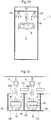
- Figs. 1-3 show a painting booth 1 for painting a painting object W (object to be painted) (a bumper of an automobile in this embodiment).
- first painting area 2a primer painting is effected on the painting object W.
- second painting area 2b No. 1 base painting is effected on the painting object W after the primer painting.
- third painting area 2c No. 2 base painting is effected on the painting object W after the No. 1 base painting.
- a spraying means 4 is disposed under a substantially perpendicularly downward orientation. This spraying means 4 sprays predetermined paint onto the painting object W.
- robot installing areas 5 provided adjacent the respective painting areas 2 are disposed side by side along the spraying area juxtaposing direction.
- these robot installing areas 5 there are respectively installed painting robots 6 for effecting painting operations in the corresponding painting areas 2.
- Two painting areas 2 adjacent each other have a mutual relation of a preceding painting area 2' disposed on the upstream side in an advancing direction of the painting object W and a subsequent painting area 2" disposed on the downstream side in the advancing direction of the painting object W.
- the first painting area 2a is the preceding painting area 2' whereas the second painting area 2b is the subsequent painting area 2" relative thereto.
- the second painting area 2b is the preceding painting area 2' whereas the third painting area 2c is the subsequent painting area 2" relative thereto.
- the third painting area 2c is the preceding painting area 2' whereas the fourth painting area 2d is the subsequent painting area 2" relative thereto.
- each painting area 2 the painting object W is held to a leading end portion 7a of an arm 7 of each painting robot 6 as being connected via a branch-like holder 8.
- This holder 8 as shown in Fig. 4 , includes a plurality of suckers 9 to be sucked to the painting object W as "a holder-painting object connecting means" for connecting this holder 8 to the painting object W.
- suckers 9 are provided in the holder 8 as being disposed in correspondence with a plurality of connection target positions in the painting object W (in this example, back face portions at the opposed ends at a front portion of the bumper and back face portions at opposed lateral portions of the bumper).
- the holder 8 is formed of a pipe member.
- An inner hole of this pipe member constitutes a suction passage 10 for sucking air inside the suckers 9 by a sucking means (not shown).
- the suction passage 10 consists of a main suction passage 10b continuous to a suction opening 10a connected to the sucking means and branch suction passages 10c branching from the main suction passage 10b and opening to the insides of the respective suckers 9.
- the main suction passage 10b incorporates a check valve 11 of e.g. a ball type.
- This check valve 11 of a ball type or the like allows flow of air from the inside of each sucker 9 toward the suction opening 10a (namely, air suction by the sucking means connected to the suction opening 10a). And, this ball-type or the like check valve 11 automatically shuts off reverse air flow (i.e. air flow from the suction opening 10a toward the inside of each sucker 9).
- each sucker 9 is sucked to the painting object W. Thereafter, even after the sucking means is detached from the suction opening 10a, reverse air flow (in other words, opening-up of each sucker 9 to the atmosphere) is prevented by this check valve 11. Therefore, the sucked state of each sucker 9 to the painting object W is maintained. With this, the connection between the holder 8 and the painting object W is maintained.
- the holder 8 includes covers 12 for the respective suckers 9. When the sucker 9 is under a non-sucked expanded state, a leading end sucking portion of the sucker 9 protrudes from the covering area of the cover 12.
- connection hole 13 is provided in the arm leading end portion 7a of the respective painting robot 6, and in correspondence with this connection hole 13, a connection projection 14 to be inserted and fitted into the connection hole 13 is formed on the holder 8.
- connection hole 13 of each arm leading end portion 7a there are formed coaxially a straight hole portion 13a having a cylindrical inner circumferential face and a tapered entrance portion 13b having a tapered inner circumferential face whose diameter progressively increases toward a hole entrance.
- connection projection 14 of the holder 8 there are formed coaxially a column-like leading end portion 14a to be fitted into the straight hole portion 13a of the connection hole 13 and a tapered stepped portion 14b to be fitted into the tapered entrance portion 13b of the connection hole 13.
- connection projection 14 of the holder 8 when the connection projection 14 of the holder 8 is to be inserted and fitted into the connection hole 13 of the respective arm leading end portion 7a, the column-like leading end portion 14a of the connection projection 14 will be brought into sliding contact with the tapered inner circumferential face of the tapered entrance portion 13ab of the connection hole 13, whereby the connection projection 14 can be guided to the center of the connection hole 13 smoothly.
- connection projection 14 a column-like outer circumferential face of the column-like leading end portion 14a of the connection projection 14 is brought into face contact with the cylindrical inner circumferential face of the straight hole portion 13a of the connection hole 13. Also, a tapered outer circumferential face of the tapered stepped portion 14b of the connection projection 14 is brought into face contact with the tapered inner circumferential face of the tapered entrance portion 13b of the connection hole 13.
- the arm leading end portion 7a of the respective painting robot 6 is connected to the holder 8 with high connection accuracy in a reliable manner.
- the suction opening 10a of the suction passage 10 in the holder 8 opens in a connection alignment face between the arm leading end portion 7a and the holder 8 (specifically, the leading end face portion of the connection projection 14).
- a permanent magnet 15 is provided in the connection hole 13 of the respective arm leading end portion 7a. This permanent magnet 15 provides a magnetic sucking action to the connection projection 14 of the holder 8 as being inserted/fitted into the connection hole 13.
- an arm side suction passage 16 is opened in the connection hole 13 of the respective arm leading end portion 7a.
- This arm side suction passage 16 provides an air suction force between the connection hole 13 and the connection projection 14 inserted/fitted therein.
- connection hole 13 of the respective arm leading end portion 7a separately from the arm side suction passage 16 for the holder connection, a detection air passage 17 is formed.
- This detection air passage 17 is opened in the inner face of the connection hole 13 which constitutes "a connection joint face" between the arm leading end portion 7a and the holder 8.
- this detection air passage 17 is closed upon establishment of connection between the arm leading end portion 7a and the holder 8 (that is, insertion/fitting of the connection projection 14 into the connection hole 13).
- Each painting robot 6 mounts a pressure applying means (not shown).
- This pressure applying means applies a predetermined positive pressure by supply of compressed air to the detection air passage 17 which is now closed in association with the establishment of connection between the arm leading end portion 7a and the holder 8.
- the respective painting robot 6 also mounts a pressure detecting means 18.
- This pressure detecting means 18 detects air pressure in the detection air passage 17.
- the connection abnormality or abnormal external force is detected.
- a controlling means 19 executes a predetermined safety measure such as emergency stop of movements of the respective painting robot 6 or issuance of an alarm.
- a ring-shaped seal for surrounding this opening. This seal partitions between an area where air suction force is applied via the arm side suction passage 16 and an area where the positive pressure is applied via the detection air passage 17.
- the controlling means 19 automatically operates the respective painting robot 6 according to a preset operational program.
- the painting object W is connected via the holder 8 to the arm leading end portion 7a of the respective painting robot 6. Under this state, with an automatic action of the painting robots 6, the painting object W is painted by downward paint spraying from the spraying means 4 while this painting object W is being displaced relative to the spraying means 4.
- the controlling means 19 displaces the painting object W relative to the spraying means 4 while changing the posture of the painting object W in such a manner as to maintain a painting progress face in the painting object W at each timing at a posture perpendicular to the direction of paint spraying from the spraying means 4.
- a transfer section 20 is provided. In this transfer section 20, reception and transfer of the painting object W between the adjacent painting robots 6 are effected.
- the painting object W after completion of painting in the preceding painting area 2' is sent via this transfer section 20 to the subsequent painting area 2".
- the controlling means 19 after completion of the preceding painting in the preceding painting area 2', the painting object W together with the holder 8 is held to the transfer section 20 between the preceding painting robot 6' and the subsequent painting robot 6", by an action of the preceding painting robot 6'.
- the arm leading end portion 7a of the preceding painting robot 6' is retracted away from the transfer section 20. Thereafter, with an action of the subsequent painting robot 6", the arm leading end portion 7a of this subsequent painting robot 6" is connected to the holder 8 which is being supported to the transfer section 20, with its connection to the painting object W being maintained. Then, the process shifts to a subsequent painting in the subsequent painting area 2".
- connection releasing means (not shown).
- connection releasing means when the air suction via the arm side suction passage 16 for holder connection is stopped, removes the connection projection 14 away from the connection hole 13 against the magnetic force of the permanent magnet 15, thereby to release the connection between the arm leading end portion 7a and the holder 8.
- controlling means 19 stops the air suction via the arm side suction passage 16 and automatically operates the connection releasing means, thereby to release the connection the arm leading end portion 7a of the preceding painting robot 6' and the holder 8 in the transfer section 20.
- the painting object W connected with the holder 8 in advance and introduced into the first painting area 2a will be caused to be held to the transfer section 21 adjacent the first painting area 2a by an operator or another robot.
- the painting object W after completion of its painting in the last fourth painting area 2d is mounted together with the holder 8 on a transport cart 22 in the vicinity of the fourth painting area 2d, by an action of the painting robot 6 for this fourth painting area 2d. Then, the connection between the arm leading end portion 7a of the painting robot 6 and the holder 8 is released. Thereafter, the painting object W, together with the holder 8 and the transport cart 22, will be sent into a drying furnace 3.
- the painting object W is softened by heat environment in the drying furnace 3. To this, by opening up the inside negative pressure of each sucker 9 of the holder 8 to the atmosphere, deformation of sucker suction portions in the painting object W is prevented.
- a partition wall 24 In this partition wall 24, there is defined a work opening 24a that allows the arm 7 of the painting robot 6 installed in the robot installing area 5 to extend into the corresponding painting area 2.
- an air feeding chamber 26 for robot installing area receives ventilation air (sa) fed from a ventilation machine (not show) through an air feeding passage 25a for robot installing area.
- each robot installing area 5 acting also as a lower wall of this air feeding chamber 26 an air feeding opening 27 is provided. This air feeding opening 27 blows the ventilation air (sa) received into the air feeding chamber 26 out into the respective robot installing area 5.
- an air feeding chamber 28 for the painting area is provided at a painting area side portion of the ceiling bosom portion of each robot installing area 5.
- This painting area air feeding chamber 28 receives ventilation air (sb) fed from the air ventilation machine via a painting area air feeding passage 25b.
- sock filters 29 (cylindrical filters) which extend from the painting area air feeding chamber 28 to one lateral wall 2w of each painting area 2. These sock filters 29 are arranged such that the spraying means 4 is disposed at the center portion between these sock filters 29 as viewed in a plan view.
- the ventilation air (sb) received in the painting area air feeding chamber 28 is fed to upper portions of the respective painting area 2 via these two sock filters 29.
- an over duct 30 is provided.
- This over duct 30 has a duct width extending over the substantially entire region of the respective painting area 2 as seen in the plan view and extends from the painting area air feeding chamber 28 to the one lateral wall 2w of the respective painting area 2.
- This air curtain air feeding opening 31 forms an air curtain (fa) which flows downward along the one lateral wall 2w of the respective painting area 2.
- the air curtain air feeding opening 31 is disposed coaxially with the spraying means in the direction of width of the respective painting area 2.
- the width size (d) of the air curtain air feeding opening 31 is smaller than the width size of the painting area one lateral wall 2w and is also smaller than a spacing distance between the two sock filters 29.
- each painting area 32 Downwardly of each painting area 2, there is formed an air discharging area 32.
- This air discharging area 32 receives air (ea) discharged downward from the painting area 2 in association with air feeding to the painting area 2 and air feeding to the corresponding robot installing area 5. And, the air (ea) received in this air discharging area 32 is discharged by an air discharging fan (not shown) via an air discharging passage 33.
- the discharge air (ea) in the air discharging area 32, the discharge air (ea) will be mixed with a powder-like collection aiding substance and on the downstream side of the air discharging passage 33, the excess sprayed paint together with the collection aiding substance may be collected by a filter.
- a wet type collection device for excess sprayed paint may be disposed in the air discharging area 32.
- each painting area 5 is maintained at a higher pressure than the adjacent painting area 2. From these robot installing areas 5, there will be formed a horizontal or obliquely downward air flow (ra) flowing into the corresponding painting area 2 through the work opening 24a defined in the partition wall 24.
- adjacent painting areas 2 are partitioned from each other by the partition wall 34 or a hanging wall or air curtain. With this arrangement, relative movement of excess sprayed paint between adjacent painting areas 2 (i.e. between the preceding painting area 2' and the subsequent painting area 2") is prevented.
- adjacent robot installing areas 5 are kept open to each other or partitioned, if any, by an air curtain, from each other. With this arrangement, reception and transfer of the painting object W via the transfer section 20 between the adjacent robot installing areas 5 (i.e. between the preceding painting robot 6' and the subsequent painting robot 6") is made easy.
- the transfer section 20 used for holding the painting object W as being connected to the holder 8 is not limited to the type configured to hold the painting object W and the holder 8 as being mounted thereon. Alternatively, this transfer section 20 can be configured as a type holding the painting object W and the holder 8 as being hung therefrom. Namely, in embodying the present invention, the manner of holding the painting object W in the transfer section 20 can vary in many ways.
- the number of the painting areas 2 to be installed can be any number which includes at least two or more painting areas 2 having the relation of the preceding painting area 2' and the subsequent painting area 2".
- the spraying means 4 respectively of the preceding painting area 2' and the subsequent painting area 2" is not limited to the one which sprays paint perpendicularly downwards.
- This spraying means 4 can spray paint obliquely downward or horizontally. Further, this spraying means 4 can be configured to be capable of changing its spraying direction.
- a plurality of spraying means 4 can be installed in the preceding painting area 2' or the subsequent painting area 2".
- These multiple spraying means 4 will be selectively used, depending on the kind of the painting object W or the kind of the sprayed paint.
- the specific shape and configuration of the holder 8 are not limited to those shown in the foregoing embodiment.
- the shape and configuration of the holder 8 can vary in any ways, depending on the painting object W.
- the holder 8 is formed of a pipe member and the inner hole (pipe hole) of this pipe member constitutes to the suction passage 10 for the respective suckers 9.
- the suction passage 10 for the respective suckers 9 can be constituted of a tube attached to the outer circumferential side of the holder 8.
- connection hole 13 can have an angular cross section, instead of the circular cross section.
- connection projection 14 to be inserted and fitted in this connection hole 13 too will have an angular cross section, instead of the circular cross section.
- connection hole 13 can be provided in the holder 8.
- connection projection 14 will be provided not in the holder 8, but in the arm leading end portion 7a of the painting robot 6.
- the arm-holder connecting means can be configured to hold the connection between the arm leading end portion 7a and the holder 8, by the magnetic force of the permanent magnet 15 only or the air suction force only.
- the arm-holder connecting means can be configured to hold the connection between the arm leading end portion 7a and the holder 8, by a magnetic force of an electromagnet or by magnetic force of an electromagnet in combination with air suction force.
- the specific mode of connection of the arm-holder connecting means can vary in many ways.
- the arm-holder connecting means is not limited to the one comprised of the connection hole 13 and the connection projection 14 to be inserted and fitted therein.
- the arm-holder connecting means can employ an air-chuck arrangement, etc.
- the configuration of the arm-holder connecting means can vary in many ways.
- the pressure applying means for applying a pressure to the detection air passage 17 which is closed in association with establishment of connection between the arm leading end portion 7a and the holder 8 can be configured to apply a negative pressure to the detection air passage 17.
- an opening/closing valve 23 may be incorporated in the main suction passage 10b of the holder 8, for instance.
- this opening/closing valve 23 will be closed in response to a command via a wireless signal from the controlling means 19, for instance.
- this opening/closing valve 23 will be opened in response to a command via a wireless signal from the controlling means 19, for instance.
- the sucking means (not shown) is connected to the suction opening 10a of the suction passage 10 only when the sucker 9 is to be sucked to the painting object W by suction of the inside air of the sucker 9.
- the sucker 9 may be sucked to the painting object W by suction of the inside air of the sucker 9 with utilization of air suction force applied through the arm side suction passage 16 which maintains the connection between the arm leading end portion 7a and the holder 8.
- the suction opening 10a of the suction passage 10 in the holder 8 need not be opened in the connection joint face between the arm leading end portion 7a and the holder 8. Instead, the suction opening 10a of the suction passage 10 can be opened in a different portion.
- the air feeding arrangement for the respective painting area 2 can be arrangements shown in Figs. 7-9 .
- a nozzle box 35 for air-curtain defining an air-curtain air feeding opening 31 in a lower face thereof is disposed at an upper portion of the one lateral wall 2w of each painting area 2.
- the sock filters 29 which extend from the painting area air feeding chamber 28 are caused to extend to the lateral face of the air-curtain nozzle box 35. And, the leading end portions of these sock filter 29 are opened to the inside of the air-curtain nozzle box 35 via a throttle opening 35a.
- the air feeding arrangement for the respective painting area 2 can be arrangements shown in Figs. 10-12 .
- paint tank installing chambers 36 which extend along the entire height of the painting area 2.
- the cross sectional shape of these paint tank installing chambers 36 as seen in a plan view is set as an approximately triangular shape which is contained within the opposed end corner portions of the one lateral wall 2w of the painting area 2.
- plan-view shape of the air-curtain air feeding opening 31 (namely, the plan view cross sectional shape of the air curtain (fa)) is set as a trapezoidal shape surrounded by the bottom side of the triangular cross sectional shape of these paint tank installing chambers 36 and the one lateral wall 2w of the painting area 2.
- the air feeding arrangement for the respective painting area 2 can be an arrangement shown in Fig. 13 .
- a lower wall 30a of the over duct 30 provided at the upper portion of the respective painting area 2 is provided with a porous structure by means of a punching plate, a filter or the like.
- the sock filters 29 are omitted and the ventilation air (sb) is discharged and fed to the upper portion of the painting area 2 via the lower wall porous structure of the over duct 30.
- the painting robot 6 to be installed in the respective robot installing area 5 is not limited to the floor mount type.
- the painting robot 6 to be installed in the respective robot installing area 5 can be any installment type such as a wall hung type or ceiling suspended type, etc.
- the spraying means 4 can be disposed to be liftable up/down in the painting area 2. With this, maintenance for the spraying means 4 can be carried out easily.
- a downwardly directed spraying means 4 will be attached to a pivot end of a parallel link mechanism 37 which is vertically pivotable.
- an urging means 38 such as a weight for urging this parallel link mechanism 37 to the rising pivotal side.
- a limit restricting means 39 such as a buffer air cylinder for restricting a pivotal range of the parallel link mechanism 37.
- the parallel link mechanism 37 will be pivotally raised to an upper limit position restricted by the limit restricting means 39.
- the spraying means 4 under the downwardly oriented posture can be maintained at an upper position in the painting area 2. And, under this state, the spraying means 4 can spray paint onto the painting object W
- the object to be painted i.e. "painting object" by the inventive painting method and painting facility is not limited to a bumper of an automobile. Namely, the inventive painting method and painting facility can be used for painting of a variety of objects.
Landscapes
- Engineering & Computer Science (AREA)
- Robotics (AREA)
- Mechanical Engineering (AREA)
- Chemical & Material Sciences (AREA)
- Analytical Chemistry (AREA)
- Physics & Mathematics (AREA)
- Fluid Mechanics (AREA)
- Spray Control Apparatus (AREA)
- Manipulator (AREA)
- Application Of Or Painting With Fluid Materials (AREA)
- Details Or Accessories Of Spraying Plant Or Apparatus (AREA)
Applications Claiming Priority (2)
| Application Number | Priority Date | Filing Date | Title |
|---|---|---|---|
| JP2014107075A JP6324210B2 (ja) | 2014-05-23 | 2014-05-23 | 塗装方法、及び、塗装設備 |
| PCT/JP2015/061122 WO2015178121A1 (ja) | 2014-05-23 | 2015-04-09 | 塗装方法、及び、塗装設備 |
Publications (3)
| Publication Number | Publication Date |
|---|---|
| EP3147035A1 true EP3147035A1 (de) | 2017-03-29 |
| EP3147035A4 EP3147035A4 (de) | 2017-07-19 |
| EP3147035B1 EP3147035B1 (de) | 2019-09-04 |
Family
ID=54553797
Family Applications (1)
| Application Number | Title | Priority Date | Filing Date |
|---|---|---|---|
| EP15795732.5A Active EP3147035B1 (de) | 2014-05-23 | 2015-04-09 | Lackierverfahren und lackieranlage |
Country Status (5)
| Country | Link |
|---|---|
| US (1) | US10335820B2 (de) |
| EP (1) | EP3147035B1 (de) |
| JP (1) | JP6324210B2 (de) |
| CN (1) | CN106457296B (de) |
| WO (1) | WO2015178121A1 (de) |
Families Citing this family (23)
| Publication number | Priority date | Publication date | Assignee | Title |
|---|---|---|---|---|
| JP6263442B2 (ja) * | 2014-05-26 | 2018-01-17 | 株式会社大気社 | 塗装設備 |
| JP6427092B2 (ja) * | 2015-12-08 | 2018-11-21 | 株式会社大気社 | 静電塗装設備 |
| WO2017145183A1 (en) * | 2016-02-27 | 2017-08-31 | Endless Robotics Pvt Ltd | System and method for painting an interior wall of housing using a semi-automatic painting robot |
| JP6772540B2 (ja) * | 2016-05-16 | 2020-10-21 | 中国電力株式会社 | 吸着装置 |
| JP2018103317A (ja) * | 2016-12-27 | 2018-07-05 | 株式会社イシダ | 吸着装置とそれが組み込まれたロボット |
| US10661307B2 (en) | 2017-03-03 | 2020-05-26 | Honda Motor Co., Ltd. | Method and system for use in applying a coating material to a vehicle |
| US11065739B2 (en) * | 2017-06-07 | 2021-07-20 | Magna Mirrors Of America, Inc. | Vehicle component painting system and method |
| TWI787529B (zh) * | 2018-07-16 | 2022-12-21 | 開曼群島商星猿哲科技國際有限公司 | 用於揀選、分類及放置複數個隨機及新物件之機器人系統 |
| US10597264B1 (en) * | 2018-12-20 | 2020-03-24 | Advanced Construction Robotics, Inc. | Semi-autonomous system for carrying and placing elongate objects |
| US11541570B2 (en) * | 2019-01-07 | 2023-01-03 | Hi-Man Lee | Coating method of board for producing concrete product and board coated by same |
| JP7194369B2 (ja) * | 2019-03-15 | 2022-12-22 | 株式会社トーアエンジニアリング | 切断された製品の加工装置 |
| JP6905550B2 (ja) | 2019-06-19 | 2021-07-21 | トリニティ工業株式会社 | 塗料ミスト除去装置及び塗装設備 |
| US12311535B2 (en) | 2019-08-07 | 2025-05-27 | RightHand Robotics, Inc. | Robotic device configuration |
| JP7498576B2 (ja) | 2020-02-25 | 2024-06-12 | トリニティ工業株式会社 | 塗料ミスト除去装置及び塗装設備 |
| US11325265B2 (en) * | 2020-06-29 | 2022-05-10 | Omnicell, Inc. | Apparatuses, systems, and methods for the grasping of objects |
| CN112495672A (zh) * | 2020-12-14 | 2021-03-16 | 范兴超 | 一种汽车保险杠的智能喷涂设备 |
| US11878316B2 (en) * | 2020-12-15 | 2024-01-23 | Gallagher-Kaiser Corporation | Sliding drawer dry filtration system for a paint booth |
| CN113414031B (zh) * | 2021-07-14 | 2022-09-23 | 广东华尚实业有限公司 | 一种板材喷涂设备 |
| CN113546800A (zh) * | 2021-08-05 | 2021-10-26 | 深圳嘉信源科技实业有限公司 | 一种降噪麦钢网加工用具有快速烘干结构的喷漆装置 |
| CN113499923B (zh) * | 2021-09-09 | 2021-12-10 | 江苏康非特动力科技有限公司 | 健身器材加工用喷漆装置 |
| CN115846107B (zh) * | 2022-11-26 | 2025-07-04 | 杭州广龙实业有限公司 | 一种纺织物无水印染设备 |
| CN116174203B (zh) * | 2023-03-10 | 2025-09-26 | 浙江中五钢管制造有限公司 | 一种不锈钢无缝管表面喷漆防腐装置 |
| CN117983468B (zh) * | 2024-04-02 | 2024-05-31 | 山东新兴安全防护设备股份有限公司 | 一种用于防弹头盔的喷漆烘干一体化处理设备 |
Family Cites Families (11)
| Publication number | Priority date | Publication date | Assignee | Title |
|---|---|---|---|---|
| JPS6134360A (ja) | 1984-07-25 | 1986-02-18 | Hitachi Ltd | 水車またはポンプ水車の調速機 |
| JPH01168371A (ja) * | 1987-12-24 | 1989-07-03 | Honda Motor Co Ltd | 塗装ブース |
| US5165969A (en) * | 1989-01-27 | 1992-11-24 | Navistar International Transportation Corp. | Recirculating paint booth and thermal oxidizer |
| JPH02117059U (de) * | 1989-03-03 | 1990-09-19 | ||
| JPH0531418A (ja) * | 1991-07-31 | 1993-02-09 | Suzuki Motor Corp | 塗装設備 |
| JPH06134360A (ja) * | 1992-10-30 | 1994-05-17 | Suzuki Motor Corp | 塗装装置 |
| JP2005103446A (ja) * | 2003-09-30 | 2005-04-21 | Toyota Motor Corp | 塗装方法および塗装装置 |
| DE102005033972A1 (de) | 2005-07-20 | 2007-01-25 | Dürr Systems GmbH | Beschichtungsverfahren und zugehörige Beschichtungseinrichtung |
| JP5560507B2 (ja) * | 2009-12-07 | 2014-07-30 | 株式会社ダイフク | 塗装用吹付処理装置 |
| DE102010032144A1 (de) * | 2010-07-24 | 2012-01-26 | Eisenmann Ag | Behandlungseinheit und Anlage zur Oberflächenbehandlung von Gegenständen |
| CN103785571B (zh) * | 2014-03-06 | 2016-03-30 | 太仓四方友信制桶有限公司 | 四工位喷涂系统及利用该系统喷涂钢桶的工艺 |
-
2014
- 2014-05-23 JP JP2014107075A patent/JP6324210B2/ja active Active
-
2015
- 2015-04-09 EP EP15795732.5A patent/EP3147035B1/de active Active
- 2015-04-09 US US15/312,327 patent/US10335820B2/en active Active
- 2015-04-09 WO PCT/JP2015/061122 patent/WO2015178121A1/ja not_active Ceased
- 2015-04-09 CN CN201580026833.8A patent/CN106457296B/zh active Active
Also Published As
| Publication number | Publication date |
|---|---|
| US20170095825A1 (en) | 2017-04-06 |
| US10335820B2 (en) | 2019-07-02 |
| JP6324210B2 (ja) | 2018-05-16 |
| EP3147035A4 (de) | 2017-07-19 |
| JP2015221418A (ja) | 2015-12-10 |
| WO2015178121A1 (ja) | 2015-11-26 |
| EP3147035B1 (de) | 2019-09-04 |
| CN106457296B (zh) | 2019-08-06 |
| CN106457296A (zh) | 2017-02-22 |
Similar Documents
| Publication | Publication Date | Title |
|---|---|---|
| US10335820B2 (en) | Painting method and painting facility | |
| EP3150288B1 (de) | Lackieranlage | |
| US9475076B2 (en) | System for treating surfaces of objects having a treatment space selectionally delimited by a conveying element | |
| KR20160115802A (ko) | 반도체 용기 보관 설비 | |
| JP2008049339A (ja) | 粉末スプレー塗装ブース | |
| WO2012038806A3 (en) | Apparatus and method for the painting of hulls of boats or the like | |
| US20180311696A1 (en) | Painting booth | |
| JP5291947B2 (ja) | 塗装ブース構造 | |
| CN101195114B (zh) | 用于粉末涂装设备的粉末涂装室 | |
| ITBG20130015U1 (it) | Cabina migliorata per la verniciatura a polvere di manufatti | |
| CN102905796B (zh) | 用于物体的表面处理的处理单元和设备 | |
| US4787330A (en) | Self-cleaning powder coating booth | |
| JP4475444B2 (ja) | 蓋で閉鎖できる容器を粉体で充填するための方法及び粉体を移送するための関連装置 | |
| JP6231439B2 (ja) | エアカーテン装置 | |
| JPH06121948A (ja) | 塗装ブースの設置方法 | |
| US9751103B2 (en) | Varnishing plant for body shops | |
| JP6875700B2 (ja) | 塗装ブース | |
| JP2005334783A5 (de) | ||
| KR101305757B1 (ko) | 도료 날림 방지장치 | |
| JPH0337742Y2 (de) | ||
| JP4244389B2 (ja) | クリーンルーム内装置 | |
| JP2008000706A (ja) | 静電粉体塗装装置 | |
| ITSP950009A1 (it) | Cabina per la verniciatura di oggetti mediante polveri. | |
| JP2006068585A (ja) | エアブロー装置 | |
| ITMI20100540A1 (it) | "apparecchiatura per la verniciatura o spruzzatura automatizzata di pezzi" |
Legal Events
| Date | Code | Title | Description |
|---|---|---|---|
| STAA | Information on the status of an ep patent application or granted ep patent |
Free format text: STATUS: THE INTERNATIONAL PUBLICATION HAS BEEN MADE |
|
| PUAI | Public reference made under article 153(3) epc to a published international application that has entered the european phase |
Free format text: ORIGINAL CODE: 0009012 |
|
| STAA | Information on the status of an ep patent application or granted ep patent |
Free format text: STATUS: REQUEST FOR EXAMINATION WAS MADE |
|
| 17P | Request for examination filed |
Effective date: 20161125 |
|
| AK | Designated contracting states |
Kind code of ref document: A1 Designated state(s): AL AT BE BG CH CY CZ DE DK EE ES FI FR GB GR HR HU IE IS IT LI LT LU LV MC MK MT NL NO PL PT RO RS SE SI SK SM TR |
|
| AX | Request for extension of the european patent |
Extension state: BA ME |
|
| A4 | Supplementary search report drawn up and despatched |
Effective date: 20170619 |
|
| RIC1 | Information provided on ipc code assigned before grant |
Ipc: B05D 1/02 20060101AFI20170612BHEP Ipc: B05B 15/12 20060101ALI20170612BHEP Ipc: B05D 1/36 20060101ALI20170612BHEP Ipc: B05B 13/02 20060101ALI20170612BHEP Ipc: B25J 15/04 20060101ALI20170612BHEP |
|
| DAV | Request for validation of the european patent (deleted) | ||
| DAX | Request for extension of the european patent (deleted) | ||
| STAA | Information on the status of an ep patent application or granted ep patent |
Free format text: STATUS: EXAMINATION IS IN PROGRESS |
|
| 17Q | First examination report despatched |
Effective date: 20180502 |
|
| REG | Reference to a national code |
Ref country code: DE Ref legal event code: R079 Ref document number: 602015037313 Country of ref document: DE Free format text: PREVIOUS MAIN CLASS: B05D0001020000 Ipc: B05B0015000000 |
|
| RAP1 | Party data changed (applicant data changed or rights of an application transferred) |
Owner name: TAIKISHA LTD. |
|
| RIC1 | Information provided on ipc code assigned before grant |
Ipc: B05B 15/00 20060101AFI20181024BHEP |
|
| GRAP | Despatch of communication of intention to grant a patent |
Free format text: ORIGINAL CODE: EPIDOSNIGR1 |
|
| STAA | Information on the status of an ep patent application or granted ep patent |
Free format text: STATUS: GRANT OF PATENT IS INTENDED |
|
| INTG | Intention to grant announced |
Effective date: 20181214 |
|
| GRAS | Grant fee paid |
Free format text: ORIGINAL CODE: EPIDOSNIGR3 |
|
| GRAJ | Information related to disapproval of communication of intention to grant by the applicant or resumption of examination proceedings by the epo deleted |
Free format text: ORIGINAL CODE: EPIDOSDIGR1 |
|
| GRAL | Information related to payment of fee for publishing/printing deleted |
Free format text: ORIGINAL CODE: EPIDOSDIGR3 |
|
| STAA | Information on the status of an ep patent application or granted ep patent |
Free format text: STATUS: EXAMINATION IS IN PROGRESS |
|
| INTC | Intention to grant announced (deleted) | ||
| GRAP | Despatch of communication of intention to grant a patent |
Free format text: ORIGINAL CODE: EPIDOSNIGR1 |
|
| STAA | Information on the status of an ep patent application or granted ep patent |
Free format text: STATUS: GRANT OF PATENT IS INTENDED |
|
| INTG | Intention to grant announced |
Effective date: 20190704 |
|
| GRAA | (expected) grant |
Free format text: ORIGINAL CODE: 0009210 |
|
| STAA | Information on the status of an ep patent application or granted ep patent |
Free format text: STATUS: THE PATENT HAS BEEN GRANTED |
|
| AK | Designated contracting states |
Kind code of ref document: B1 Designated state(s): AL AT BE BG CH CY CZ DE DK EE ES FI FR GB GR HR HU IE IS IT LI LT LU LV MC MK MT NL NO PL PT RO RS SE SI SK SM TR |
|
| REG | Reference to a national code |
Ref country code: GB Ref legal event code: FG4D |
|
| REG | Reference to a national code |
Ref country code: CH Ref legal event code: EP |
|
| REG | Reference to a national code |
Ref country code: AT Ref legal event code: REF Ref document number: 1174616 Country of ref document: AT Kind code of ref document: T Effective date: 20190915 |
|
| REG | Reference to a national code |
Ref country code: DE Ref legal event code: R096 Ref document number: 602015037313 Country of ref document: DE |
|
| REG | Reference to a national code |
Ref country code: IE Ref legal event code: FG4D |
|
| REG | Reference to a national code |
Ref country code: NL Ref legal event code: MP Effective date: 20190904 |
|
| REG | Reference to a national code |
Ref country code: LT Ref legal event code: MG4D |
|
| PG25 | Lapsed in a contracting state [announced via postgrant information from national office to epo] |
Ref country code: FI Free format text: LAPSE BECAUSE OF FAILURE TO SUBMIT A TRANSLATION OF THE DESCRIPTION OR TO PAY THE FEE WITHIN THE PRESCRIBED TIME-LIMIT Effective date: 20190904 Ref country code: LT Free format text: LAPSE BECAUSE OF FAILURE TO SUBMIT A TRANSLATION OF THE DESCRIPTION OR TO PAY THE FEE WITHIN THE PRESCRIBED TIME-LIMIT Effective date: 20190904 Ref country code: BG Free format text: LAPSE BECAUSE OF FAILURE TO SUBMIT A TRANSLATION OF THE DESCRIPTION OR TO PAY THE FEE WITHIN THE PRESCRIBED TIME-LIMIT Effective date: 20191204 Ref country code: NO Free format text: LAPSE BECAUSE OF FAILURE TO SUBMIT A TRANSLATION OF THE DESCRIPTION OR TO PAY THE FEE WITHIN THE PRESCRIBED TIME-LIMIT Effective date: 20191204 Ref country code: HR Free format text: LAPSE BECAUSE OF FAILURE TO SUBMIT A TRANSLATION OF THE DESCRIPTION OR TO PAY THE FEE WITHIN THE PRESCRIBED TIME-LIMIT Effective date: 20190904 Ref country code: SE Free format text: LAPSE BECAUSE OF FAILURE TO SUBMIT A TRANSLATION OF THE DESCRIPTION OR TO PAY THE FEE WITHIN THE PRESCRIBED TIME-LIMIT Effective date: 20190904 |
|
| PG25 | Lapsed in a contracting state [announced via postgrant information from national office to epo] |
Ref country code: RS Free format text: LAPSE BECAUSE OF FAILURE TO SUBMIT A TRANSLATION OF THE DESCRIPTION OR TO PAY THE FEE WITHIN THE PRESCRIBED TIME-LIMIT Effective date: 20190904 Ref country code: AL Free format text: LAPSE BECAUSE OF FAILURE TO SUBMIT A TRANSLATION OF THE DESCRIPTION OR TO PAY THE FEE WITHIN THE PRESCRIBED TIME-LIMIT Effective date: 20190904 Ref country code: GR Free format text: LAPSE BECAUSE OF FAILURE TO SUBMIT A TRANSLATION OF THE DESCRIPTION OR TO PAY THE FEE WITHIN THE PRESCRIBED TIME-LIMIT Effective date: 20191205 Ref country code: ES Free format text: LAPSE BECAUSE OF FAILURE TO SUBMIT A TRANSLATION OF THE DESCRIPTION OR TO PAY THE FEE WITHIN THE PRESCRIBED TIME-LIMIT Effective date: 20190904 Ref country code: LV Free format text: LAPSE BECAUSE OF FAILURE TO SUBMIT A TRANSLATION OF THE DESCRIPTION OR TO PAY THE FEE WITHIN THE PRESCRIBED TIME-LIMIT Effective date: 20190904 |
|
| REG | Reference to a national code |
Ref country code: AT Ref legal event code: MK05 Ref document number: 1174616 Country of ref document: AT Kind code of ref document: T Effective date: 20190904 |
|
| PG25 | Lapsed in a contracting state [announced via postgrant information from national office to epo] |
Ref country code: EE Free format text: LAPSE BECAUSE OF FAILURE TO SUBMIT A TRANSLATION OF THE DESCRIPTION OR TO PAY THE FEE WITHIN THE PRESCRIBED TIME-LIMIT Effective date: 20190904 Ref country code: PL Free format text: LAPSE BECAUSE OF FAILURE TO SUBMIT A TRANSLATION OF THE DESCRIPTION OR TO PAY THE FEE WITHIN THE PRESCRIBED TIME-LIMIT Effective date: 20190904 Ref country code: NL Free format text: LAPSE BECAUSE OF FAILURE TO SUBMIT A TRANSLATION OF THE DESCRIPTION OR TO PAY THE FEE WITHIN THE PRESCRIBED TIME-LIMIT Effective date: 20190904 Ref country code: IT Free format text: LAPSE BECAUSE OF FAILURE TO SUBMIT A TRANSLATION OF THE DESCRIPTION OR TO PAY THE FEE WITHIN THE PRESCRIBED TIME-LIMIT Effective date: 20190904 Ref country code: AT Free format text: LAPSE BECAUSE OF FAILURE TO SUBMIT A TRANSLATION OF THE DESCRIPTION OR TO PAY THE FEE WITHIN THE PRESCRIBED TIME-LIMIT Effective date: 20190904 Ref country code: RO Free format text: LAPSE BECAUSE OF FAILURE TO SUBMIT A TRANSLATION OF THE DESCRIPTION OR TO PAY THE FEE WITHIN THE PRESCRIBED TIME-LIMIT Effective date: 20190904 Ref country code: PT Free format text: LAPSE BECAUSE OF FAILURE TO SUBMIT A TRANSLATION OF THE DESCRIPTION OR TO PAY THE FEE WITHIN THE PRESCRIBED TIME-LIMIT Effective date: 20200106 |
|
| PG25 | Lapsed in a contracting state [announced via postgrant information from national office to epo] |
Ref country code: SK Free format text: LAPSE BECAUSE OF FAILURE TO SUBMIT A TRANSLATION OF THE DESCRIPTION OR TO PAY THE FEE WITHIN THE PRESCRIBED TIME-LIMIT Effective date: 20190904 Ref country code: IS Free format text: LAPSE BECAUSE OF FAILURE TO SUBMIT A TRANSLATION OF THE DESCRIPTION OR TO PAY THE FEE WITHIN THE PRESCRIBED TIME-LIMIT Effective date: 20200224 Ref country code: CZ Free format text: LAPSE BECAUSE OF FAILURE TO SUBMIT A TRANSLATION OF THE DESCRIPTION OR TO PAY THE FEE WITHIN THE PRESCRIBED TIME-LIMIT Effective date: 20190904 Ref country code: SM Free format text: LAPSE BECAUSE OF FAILURE TO SUBMIT A TRANSLATION OF THE DESCRIPTION OR TO PAY THE FEE WITHIN THE PRESCRIBED TIME-LIMIT Effective date: 20190904 |
|
| REG | Reference to a national code |
Ref country code: DE Ref legal event code: R097 Ref document number: 602015037313 Country of ref document: DE |
|
| PLBE | No opposition filed within time limit |
Free format text: ORIGINAL CODE: 0009261 |
|
| STAA | Information on the status of an ep patent application or granted ep patent |
Free format text: STATUS: NO OPPOSITION FILED WITHIN TIME LIMIT |
|
| PG2D | Information on lapse in contracting state deleted |
Ref country code: IS |
|
| PG25 | Lapsed in a contracting state [announced via postgrant information from national office to epo] |
Ref country code: DK Free format text: LAPSE BECAUSE OF FAILURE TO SUBMIT A TRANSLATION OF THE DESCRIPTION OR TO PAY THE FEE WITHIN THE PRESCRIBED TIME-LIMIT Effective date: 20190904 Ref country code: IS Free format text: LAPSE BECAUSE OF FAILURE TO SUBMIT A TRANSLATION OF THE DESCRIPTION OR TO PAY THE FEE WITHIN THE PRESCRIBED TIME-LIMIT Effective date: 20200105 |
|
| 26N | No opposition filed |
Effective date: 20200605 |
|
| PG25 | Lapsed in a contracting state [announced via postgrant information from national office to epo] |
Ref country code: SI Free format text: LAPSE BECAUSE OF FAILURE TO SUBMIT A TRANSLATION OF THE DESCRIPTION OR TO PAY THE FEE WITHIN THE PRESCRIBED TIME-LIMIT Effective date: 20190904 |
|
| PG25 | Lapsed in a contracting state [announced via postgrant information from national office to epo] |
Ref country code: MC Free format text: LAPSE BECAUSE OF FAILURE TO SUBMIT A TRANSLATION OF THE DESCRIPTION OR TO PAY THE FEE WITHIN THE PRESCRIBED TIME-LIMIT Effective date: 20190904 |
|
| REG | Reference to a national code |
Ref country code: CH Ref legal event code: PL |
|
| PG25 | Lapsed in a contracting state [announced via postgrant information from national office to epo] |
Ref country code: LU Free format text: LAPSE BECAUSE OF NON-PAYMENT OF DUE FEES Effective date: 20200409 Ref country code: LI Free format text: LAPSE BECAUSE OF NON-PAYMENT OF DUE FEES Effective date: 20200430 Ref country code: CH Free format text: LAPSE BECAUSE OF NON-PAYMENT OF DUE FEES Effective date: 20200430 |
|
| REG | Reference to a national code |
Ref country code: BE Ref legal event code: MM Effective date: 20200430 |
|
| PG25 | Lapsed in a contracting state [announced via postgrant information from national office to epo] |
Ref country code: BE Free format text: LAPSE BECAUSE OF NON-PAYMENT OF DUE FEES Effective date: 20200430 |
|
| PG25 | Lapsed in a contracting state [announced via postgrant information from national office to epo] |
Ref country code: IE Free format text: LAPSE BECAUSE OF NON-PAYMENT OF DUE FEES Effective date: 20200409 |
|
| PG25 | Lapsed in a contracting state [announced via postgrant information from national office to epo] |
Ref country code: TR Free format text: LAPSE BECAUSE OF FAILURE TO SUBMIT A TRANSLATION OF THE DESCRIPTION OR TO PAY THE FEE WITHIN THE PRESCRIBED TIME-LIMIT Effective date: 20190904 Ref country code: MT Free format text: LAPSE BECAUSE OF FAILURE TO SUBMIT A TRANSLATION OF THE DESCRIPTION OR TO PAY THE FEE WITHIN THE PRESCRIBED TIME-LIMIT Effective date: 20190904 Ref country code: CY Free format text: LAPSE BECAUSE OF FAILURE TO SUBMIT A TRANSLATION OF THE DESCRIPTION OR TO PAY THE FEE WITHIN THE PRESCRIBED TIME-LIMIT Effective date: 20190904 |
|
| PG25 | Lapsed in a contracting state [announced via postgrant information from national office to epo] |
Ref country code: MK Free format text: LAPSE BECAUSE OF FAILURE TO SUBMIT A TRANSLATION OF THE DESCRIPTION OR TO PAY THE FEE WITHIN THE PRESCRIBED TIME-LIMIT Effective date: 20190904 |
|
| PGFP | Annual fee paid to national office [announced via postgrant information from national office to epo] |
Ref country code: FR Payment date: 20230417 Year of fee payment: 9 Ref country code: DE Payment date: 20230307 Year of fee payment: 9 |
|
| PGFP | Annual fee paid to national office [announced via postgrant information from national office to epo] |
Ref country code: GB Payment date: 20230420 Year of fee payment: 9 |
|
| REG | Reference to a national code |
Ref country code: DE Ref legal event code: R119 Ref document number: 602015037313 Country of ref document: DE |
|
| GBPC | Gb: european patent ceased through non-payment of renewal fee |
Effective date: 20240409 |
|
| PG25 | Lapsed in a contracting state [announced via postgrant information from national office to epo] |
Ref country code: DE Free format text: LAPSE BECAUSE OF NON-PAYMENT OF DUE FEES Effective date: 20241105 |
|
| PG25 | Lapsed in a contracting state [announced via postgrant information from national office to epo] |
Ref country code: GB Free format text: LAPSE BECAUSE OF NON-PAYMENT OF DUE FEES Effective date: 20240409 |
|
| PG25 | Lapsed in a contracting state [announced via postgrant information from national office to epo] |
Ref country code: FR Free format text: LAPSE BECAUSE OF NON-PAYMENT OF DUE FEES Effective date: 20240430 |
|
| PG25 | Lapsed in a contracting state [announced via postgrant information from national office to epo] |
Ref country code: GB Free format text: LAPSE BECAUSE OF NON-PAYMENT OF DUE FEES Effective date: 20240409 Ref country code: FR Free format text: LAPSE BECAUSE OF NON-PAYMENT OF DUE FEES Effective date: 20240430 Ref country code: DE Free format text: LAPSE BECAUSE OF NON-PAYMENT OF DUE FEES Effective date: 20241105 |