EP3147440A1 - Dispositif d'insertion pour portes coulissantes - Google Patents
Dispositif d'insertion pour portes coulissantes Download PDFInfo
- Publication number
- EP3147440A1 EP3147440A1 EP16188743.5A EP16188743A EP3147440A1 EP 3147440 A1 EP3147440 A1 EP 3147440A1 EP 16188743 A EP16188743 A EP 16188743A EP 3147440 A1 EP3147440 A1 EP 3147440A1
- Authority
- EP
- European Patent Office
- Prior art keywords
- parking
- guide
- sliding door
- damper
- spring
- Prior art date
- Legal status (The legal status is an assumption and is not a legal conclusion. Google has not performed a legal analysis and makes no representation as to the accuracy of the status listed.)
- Granted
Links
Images





Classifications
-
- E—FIXED CONSTRUCTIONS
- E05—LOCKS; KEYS; WINDOW OR DOOR FITTINGS; SAFES
- E05F—DEVICES FOR MOVING WINGS INTO OPEN OR CLOSED POSITION; CHECKS FOR WINGS; WING FITTINGS NOT OTHERWISE PROVIDED FOR, CONCERNED WITH THE FUNCTIONING OF THE WING
- E05F5/00—Braking devices, e.g. checks; Stops; Buffers
- E05F5/003—Braking devices, e.g. checks; Stops; Buffers for sliding wings
-
- E—FIXED CONSTRUCTIONS
- E05—LOCKS; KEYS; WINDOW OR DOOR FITTINGS; SAFES
- E05F—DEVICES FOR MOVING WINGS INTO OPEN OR CLOSED POSITION; CHECKS FOR WINGS; WING FITTINGS NOT OTHERWISE PROVIDED FOR, CONCERNED WITH THE FUNCTIONING OF THE WING
- E05F1/00—Closers or openers for wings, not otherwise provided for in this subclass
- E05F1/08—Closers or openers for wings, not otherwise provided for in this subclass spring-actuated, e.g. for horizontally sliding wings
- E05F1/16—Closers or openers for wings, not otherwise provided for in this subclass spring-actuated, e.g. for horizontally sliding wings for sliding wings
-
- E—FIXED CONSTRUCTIONS
- E05—LOCKS; KEYS; WINDOW OR DOOR FITTINGS; SAFES
- E05Y—INDEXING SCHEME ASSOCIATED WITH SUBCLASSES E05D AND E05F, RELATING TO CONSTRUCTION ELEMENTS, ELECTRIC CONTROL, POWER SUPPLY, POWER SIGNAL OR TRANSMISSION, USER INTERFACES, MOUNTING OR COUPLING, DETAILS, ACCESSORIES, AUXILIARY OPERATIONS NOT OTHERWISE PROVIDED FOR, APPLICATION THEREOF
- E05Y2201/00—Constructional elements; Accessories therefor
- E05Y2201/20—Brakes; Disengaging means; Holders; Stops; Valves; Accessories therefor
- E05Y2201/21—Brakes
-
- E—FIXED CONSTRUCTIONS
- E05—LOCKS; KEYS; WINDOW OR DOOR FITTINGS; SAFES
- E05Y—INDEXING SCHEME ASSOCIATED WITH SUBCLASSES E05D AND E05F, RELATING TO CONSTRUCTION ELEMENTS, ELECTRIC CONTROL, POWER SUPPLY, POWER SIGNAL OR TRANSMISSION, USER INTERFACES, MOUNTING OR COUPLING, DETAILS, ACCESSORIES, AUXILIARY OPERATIONS NOT OTHERWISE PROVIDED FOR, APPLICATION THEREOF
- E05Y2201/00—Constructional elements; Accessories therefor
- E05Y2201/20—Brakes; Disengaging means; Holders; Stops; Valves; Accessories therefor
- E05Y2201/214—Disengaging means
-
- E—FIXED CONSTRUCTIONS
- E05—LOCKS; KEYS; WINDOW OR DOOR FITTINGS; SAFES
- E05Y—INDEXING SCHEME ASSOCIATED WITH SUBCLASSES E05D AND E05F, RELATING TO CONSTRUCTION ELEMENTS, ELECTRIC CONTROL, POWER SUPPLY, POWER SIGNAL OR TRANSMISSION, USER INTERFACES, MOUNTING OR COUPLING, DETAILS, ACCESSORIES, AUXILIARY OPERATIONS NOT OTHERWISE PROVIDED FOR, APPLICATION THEREOF
- E05Y2201/00—Constructional elements; Accessories therefor
- E05Y2201/20—Brakes; Disengaging means; Holders; Stops; Valves; Accessories therefor
- E05Y2201/23—Actuation thereof
- E05Y2201/232—Actuation thereof by automatically acting means
- E05Y2201/24—Actuation thereof by automatically acting means using lost motion
-
- E—FIXED CONSTRUCTIONS
- E05—LOCKS; KEYS; WINDOW OR DOOR FITTINGS; SAFES
- E05Y—INDEXING SCHEME ASSOCIATED WITH SUBCLASSES E05D AND E05F, RELATING TO CONSTRUCTION ELEMENTS, ELECTRIC CONTROL, POWER SUPPLY, POWER SIGNAL OR TRANSMISSION, USER INTERFACES, MOUNTING OR COUPLING, DETAILS, ACCESSORIES, AUXILIARY OPERATIONS NOT OTHERWISE PROVIDED FOR, APPLICATION THEREOF
- E05Y2201/00—Constructional elements; Accessories therefor
- E05Y2201/40—Motors; Magnets; Springs; Weights; Accessories therefor
- E05Y2201/404—Function thereof
- E05Y2201/41—Function thereof for closing
- E05Y2201/412—Function thereof for closing for the final closing movement
-
- E—FIXED CONSTRUCTIONS
- E05—LOCKS; KEYS; WINDOW OR DOOR FITTINGS; SAFES
- E05Y—INDEXING SCHEME ASSOCIATED WITH SUBCLASSES E05D AND E05F, RELATING TO CONSTRUCTION ELEMENTS, ELECTRIC CONTROL, POWER SUPPLY, POWER SIGNAL OR TRANSMISSION, USER INTERFACES, MOUNTING OR COUPLING, DETAILS, ACCESSORIES, AUXILIARY OPERATIONS NOT OTHERWISE PROVIDED FOR, APPLICATION THEREOF
- E05Y2600/00—Mounting or coupling arrangements for elements provided for in this subclass
- E05Y2600/40—Mounting location; Visibility of the elements
- E05Y2600/45—Mounting location; Visibility of the elements in or on the fixed frame
-
- E—FIXED CONSTRUCTIONS
- E05—LOCKS; KEYS; WINDOW OR DOOR FITTINGS; SAFES
- E05Y—INDEXING SCHEME ASSOCIATED WITH SUBCLASSES E05D AND E05F, RELATING TO CONSTRUCTION ELEMENTS, ELECTRIC CONTROL, POWER SUPPLY, POWER SIGNAL OR TRANSMISSION, USER INTERFACES, MOUNTING OR COUPLING, DETAILS, ACCESSORIES, AUXILIARY OPERATIONS NOT OTHERWISE PROVIDED FOR, APPLICATION THEREOF
- E05Y2800/00—Details, accessories and auxiliary operations not otherwise provided for
- E05Y2800/20—Combinations of elements
- E05Y2800/21—Combinations of elements of identical elements, e.g. of identical compression springs
-
- E—FIXED CONSTRUCTIONS
- E05—LOCKS; KEYS; WINDOW OR DOOR FITTINGS; SAFES
- E05Y—INDEXING SCHEME ASSOCIATED WITH SUBCLASSES E05D AND E05F, RELATING TO CONSTRUCTION ELEMENTS, ELECTRIC CONTROL, POWER SUPPLY, POWER SIGNAL OR TRANSMISSION, USER INTERFACES, MOUNTING OR COUPLING, DETAILS, ACCESSORIES, AUXILIARY OPERATIONS NOT OTHERWISE PROVIDED FOR, APPLICATION THEREOF
- E05Y2800/00—Details, accessories and auxiliary operations not otherwise provided for
- E05Y2800/20—Combinations of elements
- E05Y2800/23—Combinations of elements of elements of different categories
- E05Y2800/24—Combinations of elements of elements of different categories of springs and brakes
-
- E—FIXED CONSTRUCTIONS
- E05—LOCKS; KEYS; WINDOW OR DOOR FITTINGS; SAFES
- E05Y—INDEXING SCHEME ASSOCIATED WITH SUBCLASSES E05D AND E05F, RELATING TO CONSTRUCTION ELEMENTS, ELECTRIC CONTROL, POWER SUPPLY, POWER SIGNAL OR TRANSMISSION, USER INTERFACES, MOUNTING OR COUPLING, DETAILS, ACCESSORIES, AUXILIARY OPERATIONS NOT OTHERWISE PROVIDED FOR, APPLICATION THEREOF
- E05Y2800/00—Details, accessories and auxiliary operations not otherwise provided for
- E05Y2800/73—Multiple functions
-
- E—FIXED CONSTRUCTIONS
- E05—LOCKS; KEYS; WINDOW OR DOOR FITTINGS; SAFES
- E05Y—INDEXING SCHEME ASSOCIATED WITH SUBCLASSES E05D AND E05F, RELATING TO CONSTRUCTION ELEMENTS, ELECTRIC CONTROL, POWER SUPPLY, POWER SIGNAL OR TRANSMISSION, USER INTERFACES, MOUNTING OR COUPLING, DETAILS, ACCESSORIES, AUXILIARY OPERATIONS NOT OTHERWISE PROVIDED FOR, APPLICATION THEREOF
- E05Y2800/00—Details, accessories and auxiliary operations not otherwise provided for
- E05Y2800/74—Specific positions
- E05Y2800/75—Specific positions intermediate
-
- E—FIXED CONSTRUCTIONS
- E05—LOCKS; KEYS; WINDOW OR DOOR FITTINGS; SAFES
- E05Y—INDEXING SCHEME ASSOCIATED WITH SUBCLASSES E05D AND E05F, RELATING TO CONSTRUCTION ELEMENTS, ELECTRIC CONTROL, POWER SUPPLY, POWER SIGNAL OR TRANSMISSION, USER INTERFACES, MOUNTING OR COUPLING, DETAILS, ACCESSORIES, AUXILIARY OPERATIONS NOT OTHERWISE PROVIDED FOR, APPLICATION THEREOF
- E05Y2900/00—Application of doors, windows, wings or fittings thereof
-
- E—FIXED CONSTRUCTIONS
- E05—LOCKS; KEYS; WINDOW OR DOOR FITTINGS; SAFES
- E05Y—INDEXING SCHEME ASSOCIATED WITH SUBCLASSES E05D AND E05F, RELATING TO CONSTRUCTION ELEMENTS, ELECTRIC CONTROL, POWER SUPPLY, POWER SIGNAL OR TRANSMISSION, USER INTERFACES, MOUNTING OR COUPLING, DETAILS, ACCESSORIES, AUXILIARY OPERATIONS NOT OTHERWISE PROVIDED FOR, APPLICATION THEREOF
- E05Y2900/00—Application of doors, windows, wings or fittings thereof
- E05Y2900/20—Application of doors, windows, wings or fittings thereof for furniture, e.g. cabinets
Definitions
- the invention relates to a feeder device, in particular for sliding doors with a trigger member which is directly or indirectly coupled to a damper and a spring, wherein the trigger member from a first parking portion of a guide is movable out into a guide portion, and wherein the trigger member in the guide section opposite the damping force of the damper in the damping direction is adjustable.
- Such retraction devices are from the DE 10 2007 008 363 B3 known.
- an activator with a driver is attached to the sliding door.
- a pull-in spring is effective, the trigger part from the parking position in a Pulling pull in position.
- a damper acts on the trigger part, which dampens the pull-in force of the pull-in spring.
- sliding doors are often used, which serves to selectively cover three juxtaposed cabinet compartments. Accordingly, the sliding door can be adjusted so that it covers either the left, the right or the middle cabinet compartment.
- the sliding door can with the in the DE 10 2007 008 363 B3 shown pulling device are pulled into each of the left or right cabinet associated end position. In the middle position alignment of the sliding door is not possible with the known feeder.
- a similar feeder is also from the DE 20 2004 006 412 or the EP 1 658 785 B1 known.
- the object of the invention relating to the pull-in device is achieved in that the guide has a second parking section into which the release part is adjustable into a second parking position, and in that the second parking section is arranged offset in the direction of damping relative to the first parking section.
- the release part to have a driver receptacle, for the driver receptacle to be released in the first parking position assigned to the first parking segment and in the second parking position for receiving a driver.
- the sliding door can be adjusted out of its two end positions into the catch receptacle and thus caught by the release part.
- cam receiver is released in the first parking position counter to the damping direction and that the cam receiver is released in the second parking position in the damping direction. In this way, a simple retraction of the driver in the driver receptacle is possible.
- a particularly simple constructive embodiment results for the retraction device when it is provided that the trigger part is coupled to a carriage or has this, and that the carriage receives the trigger part adjustably.
- a particularly reliable fixation of the driver in the driver receiving succeeds in particular when it is provided that the driver receiving two stops are assigned to the determination of the driver in the driver. Then it is prevented that in a strong impact of the driver on the respective stop, the driver springs back from the driver seat.
- one or both stops are adjustable transversely to the adjusting movement of the trigger member against the bias of a spring element.
- the stops are of the shape that they can be spring back if the driver is not in its intended operating position. The driver can then move past the spring-loaded stop into the driver seat.
- the carriage with a guide lug in a carriage guide between the two parking positions associated positions is passable.
- a further preferred variant of the invention is characterized in that the release part has two guide pieces, which are guided adjustably in the guide, and that in each case a guide piece in the assigned parking position in a parking section is retractable. With the guide pieces a defined assignment of the trigger part in the parking position and thus a reliable determination of the trigger part is guaranteed.
- the trigger part is mounted on the carriage such that it performs a combined pivot-linear movement in the transition from the guide portion in the first and / or second parking section.
- the release part can be pivoted during the process in the park position and additionally be drawn into the housing of the feeder for the purpose of a low height.
- a feeder assembly in particular for sliding doors, provided with two release parts, which are respectively connected to a damper and a spring, wherein the effective direction of the damper and the springs are in opposite directions.
- Each trigger part is provided to guide the sliding door from an end position to the middle position. In this way, a damped retraction of the sliding door is achieved in the adjustment from the first end position to the middle position.
- a damped retraction movement of the sliding door in the middle position is also possible with the second trigger part.
- the sliding door is adjustable from a central position on both sides in an end position, wherein the sliding door is moved from the first end position by means of a driver against a first trigger part of a retraction device, that the first trigger part is adjusted from a parking position that the first trigger part is pulled by a spring and counter to the damping effect of a damper in the middle position, and that the trigger member is adjusted when adjusting the sliding door from the center position to the second end position into a second parking position and the driver is released.
- the driver is received in the middle position of the sliding door on a second trigger part of a second retraction device, and that upon adjustment of the sliding door from the middle position to the second end position a connected to the second trigger part spring is tense.
- This spring can be used subsequently in adjustment from the second end position to the middle position to allow retraction of the sliding door.
- a preferred variant of the invention may be of the form that when moving the sliding door from the second end position to the middle position, the spring of the second release part relaxes and the second release part is damped against the damping effect of a damper. In this way, the pull-in force of the spring is reduced continuously and damped.
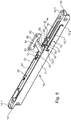
- FIG. 1 shows a retraction device 10 with a housing 11 which has a receptacle 12.
- a damper 20 is housed in the receptacle 12.
- the damper 20 is designed as an air damper and has a cylinder 21 in which a piston is linearly adjustable.
- a piston rod 22 is connected, which terminates with an end piece 23.
- the damper 20 can be fixed in the receptacle 12.
- brackets 15 are provided on the housing 11, which engage in a groove of the cylinder 21.
- a spring 30 is inserted into the receptacle 12 of the housing 11.
- the spring 30 is connected to its left-side spring end 31 at one in the FIG. 1 set bracket not shown.
- the second End 31 of the spring 30 is secured to a carriage 40 which is linearly adjustable in the housing 11.
- the piston rod 22 also engages with its end piece 23 on the carriage 40 and is connected thereto, as described below with reference to FIGS FIGS. 11 and 12 is explained in more detail.
- the carriage 40 is integrally formed as a plastic injection molded part. It has a base part 41, which has a fastening receptacle 42 with a bolt.
- the piston rod 22 is fixed with its end piece 23 in this receptacle, wherein the end piece 23 is pushed with a bore on the bolt of the fastening receptacle 42.
- the piston rod 22 is linked in the direction of its longitudinal extension immovably with the carriage 40.
- a spring holder 46 is further provided on the base part 41. At this spring holder 46, the spring end 31 of the spring 30 can be set.
- the carriage 40 is further equipped with a bearing portion 43, which connects to the base part 41.
- the bearing portion 43 forms a receptacle 44 for a trigger member 50.
- the trigger member 50 is formed like a box and has two stops 53 and 54 on. These stops 53 and 54 are in the in the FIGS. 11 and 12 shown vertical direction slidably held in the trigger member 50. In this case, the stops 53, 54 in the vertical direction downwards (according to the FIGS. 11 and 12 ) are pushed against the bias of a spring element in the trigger member 50.
- the trigger member 50 further comprises two guide pieces 51, 52, which are integrally formed as bolt-shaped projections on the trigger member 50.
- a bearing piece 55 is formed on the guide pieces 51, 52 side facing away from the support member 50.
- This bearing piece 55 protrudes beyond a flat surface of the release part 50, the flat surface abutting against the facing flat surface of the bearing portion 43 to form a sliding surface.
- the bearing piece 55 engages in a bearing seat 45 of the carriage 40.
- the bearing holder 45 is designed as a slot.
- the Trigger part 50 can therefore be pivoted relative to the carriage 40, wherein the central longitudinal axis of the journal-shaped bearing piece 55 forms the pivot axis.
- the trigger member 50 can be adjusted vertically limited in the slot-like bearing receptacle 45. The pivoting and adjusting movement of the triggering part 50 is guided over the flat contact between the bearing section 43 and the facing surface of the triggering part 50.
- the unit formed by carriage 40 and trigger member 50 is inserted into the housing 11 of the feeder 10.
- the guide pieces 51 and 52 engage in a guide 13, which is incorporated as an opening in the housing 11, a.
- the guide lug 47 of the carriage 40 engages in a carriage guide 16, which is the guide 13 opposite and is also incorporated as an opening or groove in the housing 11.
- the carriage 40 / trip unit 50 unit in the guide 13 and the slide guide 16 is guided.
- the carriage guide 16 can in particular the FIG. 5 be removed.
- the guide 13 has a guide section 13.1, which is designed as a linear section.
- Park sections 13.2 and 13.3 adjoin the guide section 13.1 on both sides.
- the parking sections 13.2 and 13.3 are connected as angled or arcuate areas of the guide portion 13.1.
- FIG. 1 shows further that flanges 14 are integrally formed on the housing 11 on both sides of the longitudinal ends.
- the flanges 14 have fastening receptacles 14.1 (see FIG. 5 ). With these fastening receptacles 14.1, the retraction device 10 can be screwed to the housing body of a piece of furniture. The feeder 10 is used to align sliding doors on this furniture.
- an activator 60 is integrally formed with a driver 61 formed thereon on the sliding door.
- the activator 60 can be screwed on the inside of the sliding door via fastening receivers 62.
- the feeder device 10 may be screwed, for example, on the ceiling side in the interior of a cabinet compartment on the sliding door facing open side of the cabinet compartment (screw 14.1).
- the driver 61 is dimensioned so that it can find space between a limited by the two stops 53 and 54 cam receiver 56 (see FIG. 2 ).
- the damper 20 is shown in its extended position, the piston rod 22 is partially pulled out of the cylinder 21 and the piston is in its end position.
- the spring 30 is in its tensioned position, whereby it exerts a pulling force on the carriage 40.
- the trigger member 50 is in its first tilted parking position, the guide piece 51 is received in the first parking section 13.2.
- the second guide piece 52 is located in the region of the guide section 13.1.
- the sliding door is moved together with the activator 60 from its right-hand end position to the left, as the arrow S in FIG. 1 illustrated.
- FIG. 1 shows the operating position shortly before hitting the driver 61 on the stop 53. If now the driver 61 strikes the stop 53, a force is applied to the stop 53. This force acts eccentrically to the pivot axis of the release part 50 formed by the bearing piece 55. In this way, a rotating torque in the counterclockwise direction on the trigger part
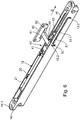
- FIG. 2 now shows the functional position of the trigger part 50 and thus of the carriage 40 just before the guide piece 52 reaches the second parking section 13.3. If now the sliding door is pulled further to the left (by the spring 30), the guide piece 52 is deflected at the arcuate end portion of the second parking section 13.3 and tilted into this parking section 13.3.
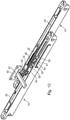
- FIG. 4 the tilted position of the trigger part 50 is shown. As this illustration shows, the stop 53 is now tilted, and the cam receiver 56 is released. Thus, the driver 61 and with him the sliding door can be further adjusted in freewheel to the left.
- a sliding door can thus be moved out of its left end position until it encounters the triggering part 50.
- the trigger part 50 then catches the sliding door and pulls it into the in FIG. 4 shown middle position into it. From the in FIG. 4 shown defined end position then the sliding door in the freewheel can be moved further into the other end position (left-side end position).
- the figure sequence must be in accordance with the
- the driver 61 first encounters the stop 54 (FIG. FIG. 4 ) and lifts it from its second parking position due to the eccentric force 13.3.
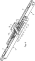
- the guide piece 52 is lifted out of the second parking section 13.3 until it reaches the region of the linear guide section 13.1 (transition from FIG FIG. 4 to FIG. 3 ).
- the trigger member 50 can be moved to the right until it reaches the area of its first parking position.
- the guide piece 51 is brought into the region of the first parking section 13.2. This is achieved by the force acting eccentrically to the pivot axis of the trigger member 50 spring force of the spring 30. This tilts the guide piece 51 down from how the Figures 2 and 1 demonstrate.
- the cam receiver 56 released and the sliding door can be moved in the freewheel to the right.
- FIG. 5 shows the functional position of the retraction device 10 according to the FIG. 4 , wherein the driver 61 is moved out of the Mit Screeniliary 56 out.
- the sliding door can now be moved to the right (arrow S) until it encounters the stop 54. Then the operating position is according to FIG. 4 reached.
- the drawing according to FIG. 4 corresponds with the drawing according to FIG. 6 ,
- FIGS. 7 to 10 is now an expanded embodiment of a feeder assembly using two intake devices 10 according to the FIGS. 1 to 6 shown.
- the two retraction devices 10 are lined up so that the directions of action of the springs 30 and the damper 20 are in opposite directions. Accordingly, the damping direction of the damper 20 of the front intake device 10 is to the left, while the damping action of the damper 20 of the second, rear intake device 10 acts to the right.
- a sliding door defined from two end positions can be pulled into the middle position. She is with it always alignable exactly in the middle position. If the sliding door now, for example, like this FIG.
- FIG. 7 shows, is moved out of its right end position to the left, it strikes the trigger part 50 of the front feed device 10. Then the above-described sequence of the feeder is active.
- the triggering part 50 moves to the left until the guide piece 52 of this first triggering part 50 is received in the associated second parking section 13.3.
- the driver 61 can run over the stop 53 of the tilted second release part 50 of the rear intake device 10 until it reaches the in FIG. 8 achieved middle position shown.
- the driver 61 is now caught on the second stop 54 of the second release part 50 of the rear intake device 10.
- the driver 61 is also fixed to the stop 54 of the front intake device 10.
- the sliding door can not be easily moved to the left or right, it is trapped in its center position.
- the sliding door If the sliding door is now to be moved from its left end stop position to the central position, it first encounters the stop 53 of the rear one Feeding device 10 and is caught on this. Under the action of force, the triggering part 50 of the rear intake device 10 can now be deflected out of the second parking position. Then, the spring 30 and the damper 20 of the rear retractor 10 is effective and pulls the sliding door in the in FIG. 8 middle position shown. The sliding door is now trapped again at its driver 61 between the two stops 54 (rear feed device 10) and 54 (front feed device 10). If the sliding door is now moved further to the right, the spring 30 of the front intake device 10 is loaded and tensioned. The damper 20 is pulled out until the operating position according to FIG. 7 is reached. Then the sliding door can be moved in the freewheel further to the left.
- the pair of figures 8 and 9 shows the switching operation, wherein the driver 61 is transferred from the cam receiver 56 of the front feed device 10 to the cam receiver 56 of the rear feed device 10.
Landscapes
- Closing And Opening Devices For Wings, And Checks For Wings (AREA)
- Fluid-Damping Devices (AREA)
- Lock And Its Accessories (AREA)
Applications Claiming Priority (3)
| Application Number | Priority Date | Filing Date | Title |
|---|---|---|---|
| DE102010000340.9A DE102010000340C5 (de) | 2010-02-08 | 2010-02-08 | Einzugvorrichtung und -anordnung für Schiebetüren sowie ein Verfahren zur Bedienung einer Schiebetür |
| EP10790951.7A EP2534326B1 (fr) | 2010-02-08 | 2010-12-13 | Dispositif d'escamotage pour portes coulissants |
| PCT/EP2010/069493 WO2011095247A1 (fr) | 2010-02-08 | 2010-12-13 | Dispositif d'escamotage pour portes coulissantes |
Related Parent Applications (2)
| Application Number | Title | Priority Date | Filing Date |
|---|---|---|---|
| EP10790951.7A Division EP2534326B1 (fr) | 2010-02-08 | 2010-12-13 | Dispositif d'escamotage pour portes coulissants |
| EP10790951.7A Division-Into EP2534326B1 (fr) | 2010-02-08 | 2010-12-13 | Dispositif d'escamotage pour portes coulissants |
Publications (3)
| Publication Number | Publication Date |
|---|---|
| EP3147440A1 true EP3147440A1 (fr) | 2017-03-29 |
| EP3147440B1 EP3147440B1 (fr) | 2021-05-19 |
| EP3147440B8 EP3147440B8 (fr) | 2021-07-07 |
Family
ID=43480959
Family Applications (2)
| Application Number | Title | Priority Date | Filing Date |
|---|---|---|---|
| EP10790951.7A Active EP2534326B1 (fr) | 2010-02-08 | 2010-12-13 | Dispositif d'escamotage pour portes coulissants |
| EP16188743.5A Active EP3147440B8 (fr) | 2010-02-08 | 2010-12-13 | Dispositif d'insertion pour portes coulissantes |
Family Applications Before (1)
| Application Number | Title | Priority Date | Filing Date |
|---|---|---|---|
| EP10790951.7A Active EP2534326B1 (fr) | 2010-02-08 | 2010-12-13 | Dispositif d'escamotage pour portes coulissants |
Country Status (6)
| Country | Link |
|---|---|
| EP (2) | EP2534326B1 (fr) |
| DE (1) | DE102010000340C5 (fr) |
| ES (1) | ES2741588T3 (fr) |
| PL (1) | PL2534326T3 (fr) |
| TR (1) | TR201911158T4 (fr) |
| WO (1) | WO2011095247A1 (fr) |
Families Citing this family (5)
| Publication number | Priority date | Publication date | Assignee | Title |
|---|---|---|---|---|
| EP2775081A3 (fr) * | 2013-03-07 | 2018-03-14 | Eugster Sicherheitstechnik | Dispositif destiné à la réception et à la libération régulées d'un entraîneur |
| CA2921440A1 (fr) * | 2015-07-29 | 2017-01-29 | Assa Abloy New Zealand Limited | Un mecanisme de fermeture |
| JP6647087B2 (ja) * | 2016-03-11 | 2020-02-14 | 株式会社ダイケン | 引戸装置 |
| GB2551712A (en) * | 2016-06-24 | 2018-01-03 | Titus D O O Dekani | Improvements in movement control devices |
| DE102022003805B4 (de) * | 2022-10-14 | 2024-09-12 | Günther Zimmer | Einzugs- und Auszugsvorrichtung mit bidirektionalen Einzugsvorrichtungen |
Citations (4)
| Publication number | Priority date | Publication date | Assignee | Title |
|---|---|---|---|---|
| DE202004006410U1 (de) | 2004-04-20 | 2005-09-01 | Alfit Ag | Einzugsautomatik mit Dämpfungsvorrichtung für Schubladen-Ausziehführungen |
| EP1658785A1 (fr) * | 2004-11-23 | 2006-05-24 | Vauth-Sagel Holding GmbH & Co. KG | Aide de fermeture pour un tiroir |
| DE102007008363B3 (de) | 2007-02-16 | 2008-09-18 | Zimmer, Günther | Zugvorrichtung mit ab- oder umgelenkter Zugfeder |
| DE202009016834U1 (de) * | 2009-12-14 | 2010-04-22 | Krischke-Lengersdorf, Christian | Einrichtung zum Dämpfen der Relativbewegung bewegter Vorrichtungsteile, insbesondere von Schiebetüren |
Family Cites Families (5)
| Publication number | Priority date | Publication date | Assignee | Title |
|---|---|---|---|---|
| DE20218927U1 (de) * | 2002-12-05 | 2003-02-13 | Hettich-Heinze GmbH & Co. KG, 32139 Spenge | Dämpfungs- und Einzugsvorrichtung für Schiebetüren |
| DE102004006412A1 (de) | 2004-02-09 | 2005-08-25 | Volkswagen Ag | Kunststoffformteil |
| DE202005004336U1 (de) * | 2005-03-17 | 2005-06-23 | Hettich-Heinze Gmbh & Co. Kg | Selbsteinzugsvorrichtung für bewegliche Möbelteile |
| DE102007009076A1 (de) * | 2007-02-23 | 2008-08-28 | Weber & Co. Gmbh Kg | Dämpfungseinrichtung für bewegbare Möbelteile |
| DE102008009046B4 (de) * | 2008-02-13 | 2014-10-02 | Günther Zimmer | Beschleunigungs- und Verzögerungsvorrichtung mit zwei Mitnahmeelementen |
-
2010
- 2010-02-08 DE DE102010000340.9A patent/DE102010000340C5/de active Active
- 2010-12-13 EP EP10790951.7A patent/EP2534326B1/fr active Active
- 2010-12-13 PL PL10790951T patent/PL2534326T3/pl unknown
- 2010-12-13 TR TR2019/11158T patent/TR201911158T4/tr unknown
- 2010-12-13 ES ES10790951T patent/ES2741588T3/es active Active
- 2010-12-13 WO PCT/EP2010/069493 patent/WO2011095247A1/fr not_active Ceased
- 2010-12-13 EP EP16188743.5A patent/EP3147440B8/fr active Active
Patent Citations (6)
| Publication number | Priority date | Publication date | Assignee | Title |
|---|---|---|---|---|
| DE202004006410U1 (de) | 2004-04-20 | 2005-09-01 | Alfit Ag | Einzugsautomatik mit Dämpfungsvorrichtung für Schubladen-Ausziehführungen |
| EP1658785A1 (fr) * | 2004-11-23 | 2006-05-24 | Vauth-Sagel Holding GmbH & Co. KG | Aide de fermeture pour un tiroir |
| EP1658785B1 (fr) | 2004-11-23 | 2008-04-30 | Vauth-Sagel Holding GmbH & Co. KG | Aide de fermeture pour un tiroir |
| DE102007008363B3 (de) | 2007-02-16 | 2008-09-18 | Zimmer, Günther | Zugvorrichtung mit ab- oder umgelenkter Zugfeder |
| DE202009016834U1 (de) * | 2009-12-14 | 2010-04-22 | Krischke-Lengersdorf, Christian | Einrichtung zum Dämpfen der Relativbewegung bewegter Vorrichtungsteile, insbesondere von Schiebetüren |
| EP2333218A1 (fr) * | 2009-12-14 | 2011-06-15 | Christian Krischke-Lengersdorf | Dispositif d'amortissement du mouvement relatif d'éléments mobiles, notamment de portes coulissantes |
Also Published As
| Publication number | Publication date |
|---|---|
| DE102010000340B4 (de) | 2016-08-11 |
| EP3147440B8 (fr) | 2021-07-07 |
| DE102010000340C5 (de) | 2019-12-05 |
| ES2741588T3 (es) | 2020-02-11 |
| WO2011095247A1 (fr) | 2011-08-11 |
| EP2534326A1 (fr) | 2012-12-19 |
| DE102010000340A1 (de) | 2011-08-11 |
| PL2534326T3 (pl) | 2019-10-31 |
| TR201911158T4 (tr) | 2019-08-21 |
| EP2534326B1 (fr) | 2019-05-15 |
| EP3147440B1 (fr) | 2021-05-19 |
Similar Documents
| Publication | Publication Date | Title |
|---|---|---|
| EP1314842B1 (fr) | Dispositif d'ouverture et de fermeture pour une partie de meuble mobile | |
| DE102015117004B3 (de) | Bewegungseinrichtung für Schubladen | |
| EP3141153B1 (fr) | Dispositif de deplacement d'un element de meuble mobile dans un sens d'ouverture par rapport a un corps d'un meuble | |
| DE202010013193U1 (de) | Öffnungs- und Schließvorrichtung für bewegbare Möbelteile und Ausstoßvorrichtung | |
| EP3238568A1 (fr) | Système de tiroir | |
| EP2353445A1 (fr) | Glissière pour retracter des parties de meubles | |
| EP1817983A1 (fr) | Dispositif pour influencer le mouvement des parties de meuble l'une par rapport à l'autre et une glissière pour tiroirs, ainsi qu'un procédé de fabrication d'un tel dispositif | |
| AT514666B1 (de) | Führungsvorrichtung für bewegbare Möbelteile | |
| EP2534326B1 (fr) | Dispositif d'escamotage pour portes coulissants | |
| DE102010061483A1 (de) | Öffnungs- und Schließvorrichtung für bewegbare Möbelteile und Ausstoßvorrichtung | |
| DE202015104434U1 (de) | Vorrichtung zum Bewegen eines bewegbaren Möbelteils sowie Möbel mit einer Vorrichtung zum Bewegen eines bewegbaren Möbelteils | |
| EP2713822B1 (fr) | Ensemble coulissant | |
| EP3142516B1 (fr) | Dispositif de rétraction destiné à un meuble | |
| DE202015104437U1 (de) | Vorrichtung zum Bewegen eines bewegbaren Möbelteils in eine Öffnungsrichtung in Bezug zu einem Möbelkorpus eines Möbels | |
| EP3132714B1 (fr) | Dispositif de déplacement d'un élément de meuble mobile dans un sens d'ouverture par rapport à un corps d'un meuble | |
| DE202009013411U1 (de) | Schließsystem eines ausziebaren Möbelteils und Möbel | |
| EP2694765B1 (fr) | Dispositif de rentrée | |
| AT514052B1 (de) | Ausstoßvorrichtung zum Ausstoßen eines bewegbaren Möbelteils | |
| DE202017103117U1 (de) | Vorrichtung zur Bewegungsbeeinflussung eines Möbelteils und Möbel | |
| DE202010000143U1 (de) | Einzugvorrichtung für Schiebetüren | |
| DE102011122269B4 (de) | Vorrichtung zur Bewegungsbeeinflussung | |
| EP2559355A1 (fr) | Dispositif destiné à déplacer une pièce de meuble mobile, unité de guidage et meuble | |
| DE102008061550A1 (de) | Dämpfungseinrichtung für Möbeltüren | |
| DE102005024529A1 (de) | Auszugführung und Auszugsperre für einen aus einem Korpus ausziehbaren Auszug |
Legal Events
| Date | Code | Title | Description |
|---|---|---|---|
| PUAI | Public reference made under article 153(3) epc to a published international application that has entered the european phase |
Free format text: ORIGINAL CODE: 0009012 |
|
| STAA | Information on the status of an ep patent application or granted ep patent |
Free format text: STATUS: THE APPLICATION HAS BEEN PUBLISHED |
|
| AC | Divisional application: reference to earlier application |
Ref document number: 2534326 Country of ref document: EP Kind code of ref document: P |
|
| AK | Designated contracting states |
Kind code of ref document: A1 Designated state(s): AL AT BE BG CH CY CZ DE DK EE ES FI FR GB GR HR HU IE IS IT LI LT LU LV MC MK MT NL NO PL PT RO RS SE SI SK SM TR |
|
| AX | Request for extension of the european patent |
Extension state: BA ME |
|
| STAA | Information on the status of an ep patent application or granted ep patent |
Free format text: STATUS: REQUEST FOR EXAMINATION WAS MADE |
|
| 17P | Request for examination filed |
Effective date: 20170929 |
|
| RBV | Designated contracting states (corrected) |
Designated state(s): AL AT BE BG CH CY CZ DE DK EE ES FI FR GB GR HR HU IE IS IT LI LT LU LV MC MK MT NL NO PL PT RO RS SE SI SK SM TR |
|
| STAA | Information on the status of an ep patent application or granted ep patent |
Free format text: STATUS: EXAMINATION IS IN PROGRESS |
|
| 17Q | First examination report despatched |
Effective date: 20190916 |
|
| GRAP | Despatch of communication of intention to grant a patent |
Free format text: ORIGINAL CODE: EPIDOSNIGR1 |
|
| STAA | Information on the status of an ep patent application or granted ep patent |
Free format text: STATUS: GRANT OF PATENT IS INTENDED |
|
| GRAS | Grant fee paid |
Free format text: ORIGINAL CODE: EPIDOSNIGR3 |
|
| INTG | Intention to grant announced |
Effective date: 20210319 |
|
| GRAA | (expected) grant |
Free format text: ORIGINAL CODE: 0009210 |
|
| STAA | Information on the status of an ep patent application or granted ep patent |
Free format text: STATUS: THE PATENT HAS BEEN GRANTED |
|
| AC | Divisional application: reference to earlier application |
Ref document number: 2534326 Country of ref document: EP Kind code of ref document: P |
|
| AK | Designated contracting states |
Kind code of ref document: B1 Designated state(s): AL AT BE BG CH CY CZ DE DK EE ES FI FR GB GR HR HU IE IS IT LI LT LU LV MC MK MT NL NO PL PT RO RS SE SI SK SM TR |
|
| REG | Reference to a national code |
Ref country code: GB Ref legal event code: FG4D Free format text: NOT ENGLISH |
|
| REG | Reference to a national code |
Ref country code: CH Ref legal event code: EP |
|
| REG | Reference to a national code |
Ref country code: DE Ref legal event code: R096 Ref document number: 502010016914 Country of ref document: DE |
|
| REG | Reference to a national code |
Ref country code: DE Ref legal event code: R081 Ref document number: 502010016914 Country of ref document: DE Owner name: TITUS D.O.O. DEKANI, SI Free format text: FORMER OWNER: KARL SIMON GMBH & CO. KG, 78733 AICHHALDEN, DE Ref country code: DE Ref legal event code: R082 Ref document number: 502010016914 Country of ref document: DE Representative=s name: HERRMANN PATENTANWAELTE, DE |
|
| REG | Reference to a national code |
Ref country code: CH Ref legal event code: PK Free format text: BERICHTIGUNG B8 Ref country code: AT Ref legal event code: REF Ref document number: 1394110 Country of ref document: AT Kind code of ref document: T Effective date: 20210615 |
|
| REG | Reference to a national code |
Ref country code: IE Ref legal event code: FG4D Free format text: LANGUAGE OF EP DOCUMENT: GERMAN |
|
| RAP2 | Party data changed (patent owner data changed or rights of a patent transferred) |
Owner name: TITUS D.O.O. DEKANI |
|
| REG | Reference to a national code |
Ref country code: LT Ref legal event code: MG9D |
|
| REG | Reference to a national code |
Ref country code: NL Ref legal event code: MP Effective date: 20210519 |
|
| PG25 | Lapsed in a contracting state [announced via postgrant information from national office to epo] |
Ref country code: LT Free format text: LAPSE BECAUSE OF FAILURE TO SUBMIT A TRANSLATION OF THE DESCRIPTION OR TO PAY THE FEE WITHIN THE PRESCRIBED TIME-LIMIT Effective date: 20210519 Ref country code: FI Free format text: LAPSE BECAUSE OF FAILURE TO SUBMIT A TRANSLATION OF THE DESCRIPTION OR TO PAY THE FEE WITHIN THE PRESCRIBED TIME-LIMIT Effective date: 20210519 Ref country code: HR Free format text: LAPSE BECAUSE OF FAILURE TO SUBMIT A TRANSLATION OF THE DESCRIPTION OR TO PAY THE FEE WITHIN THE PRESCRIBED TIME-LIMIT Effective date: 20210519 Ref country code: BG Free format text: LAPSE BECAUSE OF FAILURE TO SUBMIT A TRANSLATION OF THE DESCRIPTION OR TO PAY THE FEE WITHIN THE PRESCRIBED TIME-LIMIT Effective date: 20210819 |
|
| PG25 | Lapsed in a contracting state [announced via postgrant information from national office to epo] |
Ref country code: PL Free format text: LAPSE BECAUSE OF FAILURE TO SUBMIT A TRANSLATION OF THE DESCRIPTION OR TO PAY THE FEE WITHIN THE PRESCRIBED TIME-LIMIT Effective date: 20210519 Ref country code: PT Free format text: LAPSE BECAUSE OF FAILURE TO SUBMIT A TRANSLATION OF THE DESCRIPTION OR TO PAY THE FEE WITHIN THE PRESCRIBED TIME-LIMIT Effective date: 20210920 Ref country code: NO Free format text: LAPSE BECAUSE OF FAILURE TO SUBMIT A TRANSLATION OF THE DESCRIPTION OR TO PAY THE FEE WITHIN THE PRESCRIBED TIME-LIMIT Effective date: 20210819 Ref country code: ES Free format text: LAPSE BECAUSE OF FAILURE TO SUBMIT A TRANSLATION OF THE DESCRIPTION OR TO PAY THE FEE WITHIN THE PRESCRIBED TIME-LIMIT Effective date: 20210519 Ref country code: RS Free format text: LAPSE BECAUSE OF FAILURE TO SUBMIT A TRANSLATION OF THE DESCRIPTION OR TO PAY THE FEE WITHIN THE PRESCRIBED TIME-LIMIT Effective date: 20210519 Ref country code: SE Free format text: LAPSE BECAUSE OF FAILURE TO SUBMIT A TRANSLATION OF THE DESCRIPTION OR TO PAY THE FEE WITHIN THE PRESCRIBED TIME-LIMIT Effective date: 20210519 Ref country code: GR Free format text: LAPSE BECAUSE OF FAILURE TO SUBMIT A TRANSLATION OF THE DESCRIPTION OR TO PAY THE FEE WITHIN THE PRESCRIBED TIME-LIMIT Effective date: 20210820 Ref country code: LV Free format text: LAPSE BECAUSE OF FAILURE TO SUBMIT A TRANSLATION OF THE DESCRIPTION OR TO PAY THE FEE WITHIN THE PRESCRIBED TIME-LIMIT Effective date: 20210519 Ref country code: IS Free format text: LAPSE BECAUSE OF FAILURE TO SUBMIT A TRANSLATION OF THE DESCRIPTION OR TO PAY THE FEE WITHIN THE PRESCRIBED TIME-LIMIT Effective date: 20210919 |
|
| PG25 | Lapsed in a contracting state [announced via postgrant information from national office to epo] |
Ref country code: NL Free format text: LAPSE BECAUSE OF FAILURE TO SUBMIT A TRANSLATION OF THE DESCRIPTION OR TO PAY THE FEE WITHIN THE PRESCRIBED TIME-LIMIT Effective date: 20210519 |
|
| PG25 | Lapsed in a contracting state [announced via postgrant information from national office to epo] |
Ref country code: EE Free format text: LAPSE BECAUSE OF FAILURE TO SUBMIT A TRANSLATION OF THE DESCRIPTION OR TO PAY THE FEE WITHIN THE PRESCRIBED TIME-LIMIT Effective date: 20210519 Ref country code: CZ Free format text: LAPSE BECAUSE OF FAILURE TO SUBMIT A TRANSLATION OF THE DESCRIPTION OR TO PAY THE FEE WITHIN THE PRESCRIBED TIME-LIMIT Effective date: 20210519 Ref country code: DK Free format text: LAPSE BECAUSE OF FAILURE TO SUBMIT A TRANSLATION OF THE DESCRIPTION OR TO PAY THE FEE WITHIN THE PRESCRIBED TIME-LIMIT Effective date: 20210519 Ref country code: SM Free format text: LAPSE BECAUSE OF FAILURE TO SUBMIT A TRANSLATION OF THE DESCRIPTION OR TO PAY THE FEE WITHIN THE PRESCRIBED TIME-LIMIT Effective date: 20210519 Ref country code: SK Free format text: LAPSE BECAUSE OF FAILURE TO SUBMIT A TRANSLATION OF THE DESCRIPTION OR TO PAY THE FEE WITHIN THE PRESCRIBED TIME-LIMIT Effective date: 20210519 Ref country code: RO Free format text: LAPSE BECAUSE OF FAILURE TO SUBMIT A TRANSLATION OF THE DESCRIPTION OR TO PAY THE FEE WITHIN THE PRESCRIBED TIME-LIMIT Effective date: 20210519 |
|
| PGFP | Annual fee paid to national office [announced via postgrant information from national office to epo] |
Ref country code: DE Payment date: 20211210 Year of fee payment: 12 |
|
| REG | Reference to a national code |
Ref country code: DE Ref legal event code: R097 Ref document number: 502010016914 Country of ref document: DE |
|
| PLBE | No opposition filed within time limit |
Free format text: ORIGINAL CODE: 0009261 |
|
| STAA | Information on the status of an ep patent application or granted ep patent |
Free format text: STATUS: NO OPPOSITION FILED WITHIN TIME LIMIT |
|
| 26N | No opposition filed |
Effective date: 20220222 |
|
| PG25 | Lapsed in a contracting state [announced via postgrant information from national office to epo] |
Ref country code: IS Free format text: LAPSE BECAUSE OF FAILURE TO SUBMIT A TRANSLATION OF THE DESCRIPTION OR TO PAY THE FEE WITHIN THE PRESCRIBED TIME-LIMIT Effective date: 20210919 Ref country code: AL Free format text: LAPSE BECAUSE OF FAILURE TO SUBMIT A TRANSLATION OF THE DESCRIPTION OR TO PAY THE FEE WITHIN THE PRESCRIBED TIME-LIMIT Effective date: 20210519 |
|
| PG25 | Lapsed in a contracting state [announced via postgrant information from national office to epo] |
Ref country code: MC Free format text: LAPSE BECAUSE OF FAILURE TO SUBMIT A TRANSLATION OF THE DESCRIPTION OR TO PAY THE FEE WITHIN THE PRESCRIBED TIME-LIMIT Effective date: 20210519 Ref country code: IT Free format text: LAPSE BECAUSE OF FAILURE TO SUBMIT A TRANSLATION OF THE DESCRIPTION OR TO PAY THE FEE WITHIN THE PRESCRIBED TIME-LIMIT Effective date: 20210519 |
|
| REG | Reference to a national code |
Ref country code: CH Ref legal event code: PL |
|
| GBPC | Gb: european patent ceased through non-payment of renewal fee |
Effective date: 20211213 |
|
| REG | Reference to a national code |
Ref country code: BE Ref legal event code: MM Effective date: 20211231 |
|
| PG25 | Lapsed in a contracting state [announced via postgrant information from national office to epo] |
Ref country code: LU Free format text: LAPSE BECAUSE OF NON-PAYMENT OF DUE FEES Effective date: 20211213 Ref country code: IE Free format text: LAPSE BECAUSE OF NON-PAYMENT OF DUE FEES Effective date: 20211213 Ref country code: GB Free format text: LAPSE BECAUSE OF NON-PAYMENT OF DUE FEES Effective date: 20211213 |
|
| PG25 | Lapsed in a contracting state [announced via postgrant information from national office to epo] |
Ref country code: FR Free format text: LAPSE BECAUSE OF NON-PAYMENT OF DUE FEES Effective date: 20211231 Ref country code: BE Free format text: LAPSE BECAUSE OF NON-PAYMENT OF DUE FEES Effective date: 20211231 |
|
| PG25 | Lapsed in a contracting state [announced via postgrant information from national office to epo] |
Ref country code: LI Free format text: LAPSE BECAUSE OF NON-PAYMENT OF DUE FEES Effective date: 20211231 Ref country code: CH Free format text: LAPSE BECAUSE OF NON-PAYMENT OF DUE FEES Effective date: 20211231 |
|
| REG | Reference to a national code |
Ref country code: AT Ref legal event code: MM01 Ref document number: 1394110 Country of ref document: AT Kind code of ref document: T Effective date: 20211213 |
|
| PG25 | Lapsed in a contracting state [announced via postgrant information from national office to epo] |
Ref country code: AT Free format text: LAPSE BECAUSE OF NON-PAYMENT OF DUE FEES Effective date: 20211213 |
|
| PG25 | Lapsed in a contracting state [announced via postgrant information from national office to epo] |
Ref country code: HU Free format text: LAPSE BECAUSE OF FAILURE TO SUBMIT A TRANSLATION OF THE DESCRIPTION OR TO PAY THE FEE WITHIN THE PRESCRIBED TIME-LIMIT; INVALID AB INITIO Effective date: 20101213 Ref country code: CY Free format text: LAPSE BECAUSE OF FAILURE TO SUBMIT A TRANSLATION OF THE DESCRIPTION OR TO PAY THE FEE WITHIN THE PRESCRIBED TIME-LIMIT Effective date: 20210519 |
|
| REG | Reference to a national code |
Ref country code: DE Ref legal event code: R119 Ref document number: 502010016914 Country of ref document: DE |
|
| PG25 | Lapsed in a contracting state [announced via postgrant information from national office to epo] |
Ref country code: DE Free format text: LAPSE BECAUSE OF NON-PAYMENT OF DUE FEES Effective date: 20230701 |
|
| PG25 | Lapsed in a contracting state [announced via postgrant information from national office to epo] |
Ref country code: MK Free format text: LAPSE BECAUSE OF FAILURE TO SUBMIT A TRANSLATION OF THE DESCRIPTION OR TO PAY THE FEE WITHIN THE PRESCRIBED TIME-LIMIT Effective date: 20210519 |
|
| PG25 | Lapsed in a contracting state [announced via postgrant information from national office to epo] |
Ref country code: TR Free format text: LAPSE BECAUSE OF FAILURE TO SUBMIT A TRANSLATION OF THE DESCRIPTION OR TO PAY THE FEE WITHIN THE PRESCRIBED TIME-LIMIT Effective date: 20210519 |
|
| PG25 | Lapsed in a contracting state [announced via postgrant information from national office to epo] |
Ref country code: MT Free format text: LAPSE BECAUSE OF FAILURE TO SUBMIT A TRANSLATION OF THE DESCRIPTION OR TO PAY THE FEE WITHIN THE PRESCRIBED TIME-LIMIT Effective date: 20210519 |