EP3196392B1 - Elektromotorischer antrieb mit schliessfeder - Google Patents
Elektromotorischer antrieb mit schliessfeder Download PDFInfo
- Publication number
- EP3196392B1 EP3196392B1 EP16203235.3A EP16203235A EP3196392B1 EP 3196392 B1 EP3196392 B1 EP 3196392B1 EP 16203235 A EP16203235 A EP 16203235A EP 3196392 B1 EP3196392 B1 EP 3196392B1
- Authority
- EP
- European Patent Office
- Prior art keywords
- opening
- control device
- hydraulic
- door
- torque
- Prior art date
- Legal status (The legal status is an assumption and is not a legal conclusion. Google has not performed a legal analysis and makes no representation as to the accuracy of the status listed.)
- Active
Links
Images

Classifications
-
- E—FIXED CONSTRUCTIONS
- E05—LOCKS; KEYS; WINDOW OR DOOR FITTINGS; SAFES
- E05F—DEVICES FOR MOVING WINGS INTO OPEN OR CLOSED POSITION; CHECKS FOR WINGS; WING FITTINGS NOT OTHERWISE PROVIDED FOR, CONCERNED WITH THE FUNCTIONING OF THE WING
- E05F3/00—Closers or openers with braking devices, e.g. checks; Construction of pneumatic or liquid braking devices
- E05F3/22—Additional arrangements for closers, e.g. for holding the wing in opened or other position
- E05F3/224—Additional arrangements for closers, e.g. for holding the wing in opened or other position for assisting in opening the wing
-
- E—FIXED CONSTRUCTIONS
- E05—LOCKS; KEYS; WINDOW OR DOOR FITTINGS; SAFES
- E05F—DEVICES FOR MOVING WINGS INTO OPEN OR CLOSED POSITION; CHECKS FOR WINGS; WING FITTINGS NOT OTHERWISE PROVIDED FOR, CONCERNED WITH THE FUNCTIONING OF THE WING
- E05F15/00—Power-operated mechanisms for wings
- E05F15/60—Power-operated mechanisms for wings using electrical actuators
- E05F15/603—Power-operated mechanisms for wings using electrical actuators using rotary electromotors
- E05F15/611—Power-operated mechanisms for wings using electrical actuators using rotary electromotors for swinging wings
- E05F15/63—Power-operated mechanisms for wings using electrical actuators using rotary electromotors for swinging wings operated by swinging arms
-
- E—FIXED CONSTRUCTIONS
- E05—LOCKS; KEYS; WINDOW OR DOOR FITTINGS; SAFES
- E05F—DEVICES FOR MOVING WINGS INTO OPEN OR CLOSED POSITION; CHECKS FOR WINGS; WING FITTINGS NOT OTHERWISE PROVIDED FOR, CONCERNED WITH THE FUNCTIONING OF THE WING
- E05F1/00—Closers or openers for wings, not otherwise provided for in this subclass
- E05F1/08—Closers or openers for wings, not otherwise provided for in this subclass spring-actuated, e.g. for horizontally sliding wings
- E05F1/10—Closers or openers for wings, not otherwise provided for in this subclass spring-actuated, e.g. for horizontally sliding wings for swinging wings, e.g. counterbalance
-
- E—FIXED CONSTRUCTIONS
- E05—LOCKS; KEYS; WINDOW OR DOOR FITTINGS; SAFES
- E05F—DEVICES FOR MOVING WINGS INTO OPEN OR CLOSED POSITION; CHECKS FOR WINGS; WING FITTINGS NOT OTHERWISE PROVIDED FOR, CONCERNED WITH THE FUNCTIONING OF THE WING
- E05F15/00—Power-operated mechanisms for wings
- E05F15/70—Power-operated mechanisms for wings with automatic actuation
- E05F15/72—Power-operated mechanisms for wings with automatic actuation responsive to emergency conditions, e.g. fire
-
- E—FIXED CONSTRUCTIONS
- E05—LOCKS; KEYS; WINDOW OR DOOR FITTINGS; SAFES
- E05Y—INDEXING SCHEME ASSOCIATED WITH SUBCLASSES E05D AND E05F, RELATING TO CONSTRUCTION ELEMENTS, ELECTRIC CONTROL, POWER SUPPLY, POWER SIGNAL OR TRANSMISSION, USER INTERFACES, MOUNTING OR COUPLING, DETAILS, ACCESSORIES, AUXILIARY OPERATIONS NOT OTHERWISE PROVIDED FOR, APPLICATION THEREOF
- E05Y2400/00—Electronic control; Electrical power; Power supply; Power or signal transmission; User interfaces
- E05Y2400/10—Electronic control
- E05Y2400/30—Electronic control of motors
- E05Y2400/3013—Electronic control of motors during manual wing operation
- E05Y2400/3015—Power assistance
-
- E—FIXED CONSTRUCTIONS
- E05—LOCKS; KEYS; WINDOW OR DOOR FITTINGS; SAFES
- E05Y—INDEXING SCHEME ASSOCIATED WITH SUBCLASSES E05D AND E05F, RELATING TO CONSTRUCTION ELEMENTS, ELECTRIC CONTROL, POWER SUPPLY, POWER SIGNAL OR TRANSMISSION, USER INTERFACES, MOUNTING OR COUPLING, DETAILS, ACCESSORIES, AUXILIARY OPERATIONS NOT OTHERWISE PROVIDED FOR, APPLICATION THEREOF
- E05Y2900/00—Application of doors, windows, wings or fittings thereof
- E05Y2900/10—Application of doors, windows, wings or fittings thereof for buildings or parts thereof
- E05Y2900/13—Type of wing
- E05Y2900/132—Doors
- E05Y2900/134—Fire doors
-
- E—FIXED CONSTRUCTIONS
- E05—LOCKS; KEYS; WINDOW OR DOOR FITTINGS; SAFES
- E05Y—INDEXING SCHEME ASSOCIATED WITH SUBCLASSES E05D AND E05F, RELATING TO CONSTRUCTION ELEMENTS, ELECTRIC CONTROL, POWER SUPPLY, POWER SIGNAL OR TRANSMISSION, USER INTERFACES, MOUNTING OR COUPLING, DETAILS, ACCESSORIES, AUXILIARY OPERATIONS NOT OTHERWISE PROVIDED FOR, APPLICATION THEREOF
- E05Y2900/00—Application of doors, windows, wings or fittings thereof
- E05Y2900/10—Application of doors, windows, wings or fittings thereof for buildings or parts thereof
- E05Y2900/13—Type of wing
- E05Y2900/148—Windows
Definitions
- the invention relates to an electric motor drive for a sash, in particular a rotating sash, a door or a window, with a housing, an output axle which is rotatably mounted in the housing and can be coupled to the door or window sash or a frame, a motor for driving the output axle, a spring unit which is tensioned during a respective opening movement of the door or window sash and relaxes during a respective closing movement of the door or window sash in order to provide a closing torque, and a control device for controlling the motor.
- non-hydraulic door or window drives are used to close the wing of an open door or window using a motor. This is particularly important for smoke and fire protection doors, which must be closed quickly and reliably in the event of an alarm, especially after a noise detector has been triggered.
- the spring closure can also be supported by the drive motor.
- the previously common non-hydraulic electric motor drives when opening manually, only support for the opening process is possible in the manner of a pure opening servo drive, in which the door or window sash can be opened without force like a sash without a closer.
- the piston of the drive is kept floating by compensating for the spring force of the spring unit.
- overcompensating the spring force for automatic opening of the door or window sash is not possible with the previously known non-hydraulic electric motor drives of the type mentioned at the beginning.
- DE 10 2011 055491 A1 discloses a non-hydraulic electric motor drive for a leaf, with a motor unit which is designed to support manual opening of the door leaf and simultaneous tensioning of the mechanical energy storage.
- the invention is based on the object of specifying a non-hydraulic electric motor drive of the type mentioned at the outset, which can be used in a respective case Manual opening process also enables overcompensation of the spring force of the spring unit for automatic opening of the door or window sash, in particular to facilitate the manual opening of the door or window sash against any possible overpressure or counterpressure.
- the electric motor drive according to the invention for a sash, in particular a rotating sash, a door or a window comprises a housing, an output axle which is rotatably mounted in the housing and can be coupled to the door or window sash or a frame, a motor for driving the output axle, a spring unit, which is tensioned during a respective opening movement of the door or window sash and relaxes during a respective closing movement of the door or window sash in order to provide a closing torque, and a control device for controlling the motor.
- the control device is designed in such a way that by appropriately controlling the motor during a respective opening movement of the door or window sash, a basic closing moment is generated, by which the respective spring force of the spring unit, which depends on the opening angle, is at least substantially compensated, and at least in this case that the door or window sash is opened manually and a corresponding opening command is sent to the control device, an additional opening torque is generated.
- a respective opening command for a corresponding overcompensation can be generated, for example, as soon as it is determined by means of a sensor or the like that the door or window sash is or should be opened manually.
- the control device is preferably designed in such a way that for a respective manual opening process and an opening command is present, the additional opening torque generated is in a range from 0 to 40 Nm.
- control device is designed in such a way that the additional opening torque generated during a manual opening process and an opening command is present is only generated during a predeterminable period of time. This ensures that the door or window sash then closes securely again.
- the control device is designed in such a way that any excess pressure that occurs when opening the door or window sash is at least compensated for by the additional opening torque generated during a possible opening process and an existing opening command. This makes it easier to open the door or window sash, for example in cases where the door or window sash is blocked or slowed down by a headwind or needs to be pressed shut more strongly for other reasons.
- control device is designed or programmed in such a way that the additional opening torque generated during a manual opening process and an existing opening command is dependent on the Opening speed of the door or window sash is controlled and / or regulated.
- the control device is preferably designed in such a way that the additional opening torque generated during a manual opening process and an existing opening command is controlled and/or regulated in such a way that a predeterminable maximum opening speed of the door or window sash is not exceeded. This not only ensures that the opening process is as controlled as possible, it also prevents the door or window sash from opening uncontrollably.
- the motor can be coupled to the output axle via a gearbox.
- the control device can be connected to a sensor, in particular assigned to the transmission.
- the sensor for detecting the opening speed of the door or window leaf expediently comprises at least one rotary angle sensor. It is particularly advantageous if such a sensor for detecting the opening speed of the door or window sash comprises at least one non-contact, in particular magnetic or optical, rotation angle sensor.
- the sensor for detecting the opening speed of the door or window leaf is advantageously assigned to the first stage of the transmission.
- control device is also designed in such a way that even in the event that a fire alarm is signaled to the control device, not only a basic torque but also an additional opening torque is generated.
- the control device is advantageously designed in such a way that a higher additional opening torque is generated when a fire alarm is signaled than during a manual opening process and an opening command is present.
- the control device can, for example, be designed so that the opening torque generated when a fire alarm is signaled is in a range from 0 to 70 Nm.
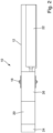
- Fig. 1 and 2 show a schematic representation of an exemplary embodiment of an electric motor drive 10 according to the invention for one Wing, in particular a rotating wing, a door or a window, which is shown in the illustration Fig. 1
- it is intended as an overhead door closer for a revolving door.
- the electric motor drive 10 comprises a housing 12, an output axle 18 which is rotatably mounted in the housing 12 and can be coupled to the door or window sash 14 or a frame 16, a motor 20, in particular an electric motor, for driving the output axle 18, a spring unit 22, which is tensioned during a respective opening movement of the door or window leaf 14 and relaxed during a respective closing movement of the door or window leaf 14 in order to provide a closing torque, and a control device 24 for controlling the motor 20.
- the electric motor drive 10 is intended, for example, as an overhead door closer for a revolving door.
- the housing 12 with the output axle 18 is attached to the door leaf 14.
- the output axis 18 is connected to a lever 28, which is provided with a sliding block or the like, which is guided in a slide rail 30 fixed to the frame 16.
- the control device 24 is designed or programmed in such a way that a basic closing torque is generated by a corresponding control of the motor 20 during a respective opening movement of the door or window sash 14, by which the respective spring force of the spring unit 22, which depends on the opening angle, is at least substantially compensated is, and at least in the case that the door or window sash 14 is opened manually and the control device 24 is supplied with a corresponding opening command, an additional opening torque T z is generated.
- the control device 24 can, for example, be designed or programmed in such a way that during a manual opening process and an existing one Opening command, the additional opening torque T z generated is in a range from 0 to 40 Nm.
- control device 24 can in particular also be designed in such a way that the additional opening torque T z generated during a manual opening process and an existing opening command is only generated during a predeterminable period of time. This ensures that the door or window sash 14 then closes securely again.
- the predeterminable time period can be, for example, in a range from 0 to 20 s.
- the additional opening torque T z generated during a manual opening process and an existing opening command can at least compensate for any excess pressure or overload that occurs when the door or window sash 14 is opened.
- the additional opening torque T z generated during a manual opening process and an existing opening command is controlled and/or regulated depending on the opening speed v of the door or window sash 14.
- control device 24 is expediently designed in such a way that the additional opening torque T z generated during a manual opening process and an existing opening command is controlled and/or regulated in such a way that that a predeterminable maximum opening speed of the door or window sash 14 is not exceeded.
- the motor 20 is coupled to the output axle 18 via a gear 26.
- the control device 24 can be connected to a sensor assigned in particular to the transmission 26.
- a sensor for detecting the opening speed v of the door or window sash 14 can in particular include at least one rotary angle sensor.
- Such a sensor for detecting the opening speed v of the door or window sash 14 includes in particular at least one non-contact, in particular magnetic or optical, rotation angle sensor.
- the sensor for detecting the opening speed v of the door or window sash 14 can in particular be assigned to the first stage of the transmission 26.
- the control device 24 can also be designed in such a way that even in the event that a fire alarm is signaled to the control device 24, not only a basic torque but also an additional opening torque is generated.
- the control device 24 is expediently designed or programmed in such a way that a higher additional opening torque is generated when a fire alarm is signaled than during a manual opening process.
- the additional opening torque generated when a fire alarm is signaled can, for example, be in a range of 0 to 70 Nm.
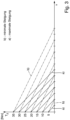
- Fig. 3 shows two exemplary groups of curves of the additional opening torque generated during a manual opening process as a function of the opening speed of the door or window sash 14.
- the control lines labeled a) correspond to those dependent on the opening speed v
- the opening speed v of the door or window sash 14 can be set to a predeterminable level via the additional opening torque T z generated Value can be regulated. If the current opening speed v decreases compared to the specified target speed, for example due to an overload, the additional opening torque T z is increased until the target speed is reached again.
- the additional opening torque T z is increased more quickly with a respective drop in speed when the motor 20 is activated according to the control curves a) (maximum slope) than when activated according to the control curves b) (minimum gradient). Controlling the speed v to the specified setpoint via the additional opening torque T z is therefore more sensitive in case a) than in case b).
- control device 24 in which the slope of the torque speed curve is adjustable.
Landscapes
- Business, Economics & Management (AREA)
- Emergency Management (AREA)
- Power-Operated Mechanisms For Wings (AREA)
Description
- Die Erfindung betrifft einen elektromotorischen Antrieb für einen Flügel, insbesondere einen Drehflügel, einer Tür oder eines Fensters, mit einem Gehäuse, einer drehbar im Gehäuse gelagerten und mit dem Tür- bzw. Fensterflügel oder einem Blendrahmen koppelbaren Abtriebsachse, einem Motor zum Antreiben der Abtriebsachse, einer Federeinheit, die während einer jeweiligen Öffnungsbewegung des Tür- bzw. Fensterflügels gespannt wird und sich während einer jeweiligen Schließbewegung des Tür- bzw. Fensterflügels entspannt, um ein Schließmoment zu liefern, und einer Steuerungseinrichtung zur Ansteuerung des Motors.
- Derartige nichthydraulische Tür- bzw. Fensterantriebe dienen dazu, den Flügel einer geöffneten Tür bzw. eines geöffneten Fensters motorisch zu schließen. Dies ist insbesondere bei Rauch- und Feuerschutztüren von Bedeutung, die im Alarmfall insbesondere nach Ansprechen eines Rauschmelders schnell und zuverlässig geschlossen werden müssen. Bei einem jeweiligen manuellen Schließen des Tür- bzw. Fensterflügels kann die Federschließung zusätzlich durch den Motor des Antriebs unterstützt werden. Anders als bei einer hydraulischen Schließereinrichtung ist bei den bisher üblichen nichthydraulischen elektromotorischen Antrieben beim manuellen Öffnen jedoch lediglich eine Unterstützung des Öffnungsvorgangs nach Art eines reinen Öffnungs-Servoantriebs möglich, bei dem der Tür- bzw. Fensterflügel wie ein Flügel ohne Schließer kraftlos geöffnet werden kann. Dabei wird der Kolben des Antriebs schwimmend gehalten, indem die Federkraft der Federeinheit kompensiert wird. Ein Überkompensieren der Federkraft für ein selbsttätiges Öffnen des Tür- bzw. Fensterflügels ist bei den bisher bekannten nichthydraulischen elektromotorischen Antrieben der eingangs genannten Art jedoch nicht möglich.
-
DE 10 2011 055491 A1 offenbart einen nichthydraulischen elektromotorischen Antrieb für einen Flügel, mit einer Motoreinheit die dazu ausgebildet ist, ein manuelles Öffnen des Türflügels und ein gleichzeitiges Spannen des mechanischen Energiespeichers zu unterstützen. - Der Erfindung liegt die Aufgabe zugrunde, einen nichthydraulischen elektromotorischen Antrieb der eingangs genannten Art anzugeben, der bei einem jeweiligen manuellen Öffnungsvorgang auch ein Überkompensieren der Federkraft der Federeinheit für ein selbsttätiges Öffnen des Tür- bzw. Fensterflügels ermöglicht, um insbesondere auch das manuelle Öffnen des Tür- bzw. Fensterflügels gegen einen eventuellen Über- oder Gegendruck zu erleichtern.
- Die Aufgabe wird erfindungsgemäß durch einen nichthydraulischen elektromotorischen Antrieb mit den Merkmalen des Anspruchs 1 gelöst. Bevorzugte Ausführungsformen des erfindungsgemäßen elektromotorischen Antriebs ergeben sich aus den Unteransprüchen, der vorliegenden Beschreibung sowie der Zeichnung.
- Der erfindungsgemäße elektromotorische Antrieb für einen Flügel, insbesondere einen Drehflügel, einer Tür oder eines Fensters umfasst ein Gehäuse, eine drehbar im Gehäuse gelagerte und mit dem Tür- bzw. Fensterflügel oder einem Blendrahmen koppelbare Abtriebsachse, einen Motor zum Antreiben der Abtriebsachse, eine Federeinheit, die während einer jeweiligen Öffnungsbewegung des Tür- bzw. Fensterflügels gespannt wird und sich während einer jeweiligen Schließbewegung des Tür- bzw. Fensterflügels entspannt, um ein Schließmoment zu liefern, und eine Steuerungseinrichtung zur Ansteuerung des Motors. Dabei ist die Steuerungseinrichtung so ausgeführt, dass durch eine entsprechende Ansteuerung des Motors während einer jeweiligen Öffnungsbewegung des Tür- bzw. Fensterflügels ein Basisschließmoment erzeugt wird, durch das die jeweilige vom Öffnungswinkel abhängige Federkraft der Federeinheit zumindest im Wesentlichen kompensiert wird, und zumindest in dem Fall, dass der Tür- bzw. Fensterflügel manuell geöffnet und der Steuerungseinrichtung ein entsprechender Öffnungsbefehl zugeführt wird, ein zusätzliches Öffnungsmoment erzeugt wird.
- Aufgrund dieser Ausbildung ist mit dem nichthydraulischen elektromotorischen Antrieb nunmehr bei einem jeweiligen manuellen Öffnungsvorgang auch ein Überkompensieren der Federkraft der Federeinheit für ein selbsttätiges Öffnen des Tür- bzw. Fensterflügels möglich, so dass insbesondere auch das manuelle Öffnen des Tür- bzw. Fensterflügels gegen einen eventuellen Über- oder Gegendruck erleichtert wird. Dabei kann ein jeweiliger Öffnungsbefehl für eine entsprechende Überkompensation beispielsweise generiert werden, sobald mittels eines Sensors oder dergleichen festgestellt wird, dass der Tür- bzw. Fensterflügel manuell geöffnet wird oder geöffnet werden soll.
- Bevorzugt ist die Steuerungseinrichtung so ausgeführt, dass bei einem jeweiligen manuellen Öffnungsvorgang und einem vorliegenden Öffnungsbefehl das erzeugte zusätzliche Öffnungsmoment in einem Bereich von 0 bis 40 Nm liegt.
- Von Vorteil ist zudem, wenn die Steuerungseinrichtung so ausgeführt ist, dass das bei einem manuellen Öffnungsvorgang und einem vorliegenden Öffnungsbefehl erzeugte zusätzliche Öffnungsmoment nur während einer vorgebbaren Zeitdauer erzeugt wird. Damit ist sichergestellt, dass der Tür- bzw. Fensterflügel anschließend wieder sicher schließt.
- Gemäß einer zweckmäßigen praktischen Ausführungsform des erfindungsgemä-ßen elektromotorischen Antriebs ist die Steuerungseinrichtung so ausgeführt, dass durch das bei einem eventuellen Öffnungsvorgang und einem vorliegenden Öffnungsbefehl erzeugte zusätzliche Öffnungsmoment ein jeweiliger beim Öffnen des Tür- bzw. Fensterflügels auftretender Überdruck zumindest kompensiert wird. Damit wird das Öffnen des Tür- bzw. Fensterflügels beispielsweise auch in solchen Fällen erleichtert, in denen der Tür- bzw. Fensterflügel blockiert oder durch Gegenwind abgebremst wird oder aus anderen Gründen stärker zugedrückt werden muss.
- Erfindungsgemäß ist die Steuerungseinrichtung so ausgeführt bzw. programmiert, dass das bei einem manuellen Öffnungsvorgang und einem vorliegenden Öffnungsbefehl erzeugte zusätzliche Öffnungsmoment in Abhängigkeit von der Öffnungsgeschwindigkeit des Tür- bzw. Fensterflügels gesteuert und/oder geregelt wird.
- Bevorzugt ist die Steuerungseinrichtung so ausgeführt, dass das bei einem manuellen Öffnungsvorgang und einem vorliegenden Öffnungsbefehl erzeugte zusätzliche Öffnungsmoment so gesteuert und/oder geregelt wird, dass eine vorgebbare maximale Öffnungsgeschwindigkeit des Tür- bzw. Fensterflügels nicht überschritten wird. Damit wird nicht nur ein möglichst kontrollierter Öffnungsvorgang sichergestellt, es wird auch verhindert, dass der Tür- bzw. Fensterflügel unkontrolliert aufschlägt.
- Der Motor kann über ein Getriebe mit der Abtriebsachse gekoppelt sein.
- Zur Erfassung der Öffnungsgeschwindigkeit des Tür- bzw. Fensterflügels kann die Steuerungseinrichtung mit einem insbesondere dem Getriebe zugeordneten Sensor verbunden sein. Dabei umfasst der Sensor zur Erfassung der Öffnungsgeschwindigkeit des Tür- bzw. Fensterflügels zweckmäßigerweise wenigstens einen Drehwinkelgeber. Von Vorteil ist insbesondere, wenn ein solcher Sensor zur Erfassung der Öffnungsgeschwindigkeit des Tür- bzw. Fensterflügels wenigstens einen berührungslosen, insbesondere magnetischen oder optischen Drehwinkelgeber umfasst.
- Vorteilhafterweise ist der Sensor zur Erfassung der Öffnungsgeschwindigkeit des Tür- bzw. Fensterflügels der ersten Stufe des Getriebes zugeordnet.
- Bevorzugt ist die Steuerungseinrichtung zudem so ausgeführt, dass auch in dem Fall, dass der Steuerungseinrichtung ein Brandalarm signalisiert wird, nicht nur ein Basismoment, sondern auch ein zusätzliches Öffnungsmoment erzeugt wird. Dabei ist die Steuerungseinrichtung vorteilhafterweise so ausgeführt, dass bei einem signalisierten Brandalarm ein höheres zusätzliches Öffnungsmoment erzeugt wird, als bei einem manuellen Öffnungsvorgang und einem vorliegenden Öffnungsbefehl. Dabei kann die Steuerungseinrichtung beispielsweise so ausgeführt sein, dass das bei einem signalisierten Brandalarm erzeugte Öffnungsmoment in einem Bereich von 0 bis 70 Nm liegt.
- Die Erfindung wird im Folgenden anhand eines Ausführungsbeispiels unter Bezugnahme auf die Zeichnung näher beschrieben; in dieser zeigen:
- Fig. 1
- eine schematische Darstellung einer beispielhaften Ausführungsform eines beispielsweise als Obentürschließer vorgesehenen erfindungsgemäßen elektromotorischen Antriebs,
- Fig. 2
- eine schematische Schnittdarstellung des elektromotorischen Antriebs gemäß
Fig. 1 und - Fig. 3
- zwei beispielhafte Gruppen von Verläufen des bei einem manuellen Öffnungsvorgang erzeugten zusätzlichen Öffnungsmoments in Abhängigkeit von der Öffnungsgeschwindigkeit des Tür- bzw. Fensterflügels.
- Die
Fig. 1 und2 zeigen in schematischer Darstellung eine beispielhafte Ausführungsform eines erfindungsgemäßen elektromotorischen Antriebs 10 für einen Flügel, insbesondere einen Drehflügel, einer Tür oder eines Fensters, der in der Darstellung gemäßFig. 1 beispielsweise als Obentürschließer für eine Drehtür vorgesehen ist. - Der elektromotorische Antrieb 10 umfasst ein Gehäuse 12, eine drehbar im Gehäuse 12 gelagerte und mit dem Tür- bzw. Fensterflügel 14 oder einem Blendrahmen 16 koppelbare Abtriebsachse 18, einen Motor 20, insbesondere Elektromotor, zum Antreiben der Abtriebsachse 18, eine Federeinheit 22, die während einer jeweiligen Öffnungsbewegung des Tür- bzw. Fensterflügels 14 gespannt wird und sich während einer jeweiligen Schließbewegung des Tür- bzw. Fensterflügels 14 entspannt, um ein Schließmoment zu liefern, und eine Steuerungseinrichtung 24 zum Ansteuern des Motors 20.
- in der Darstellung gemäß
Fig. 1 ist der elektromotorische Antrieb 10 beispielsweise als Obentürschließer für eine Drehtür vorgesehenen. Das Gehäuse 12 mit der Abtriebsachse 18 ist am Türflügel 14 angebracht. Die Abtriebsachse 18 ist mit einem Hebel 28 verbunden, der mit einem Gleitstein oder dergleichen versehenen ist, der in einer am Blendrahmen 16 fixierten Gleitschiene 30 geführt ist. - Dabei ist die Steuerungseinrichtung 24 so ausgeführt bzw. programmiert, dass durch eine entsprechende Ansteuerung des Motors 20 während einer jeweiligen Öffnungsbewegung des Tür- bzw. Fensterflügels 14 ein Basisschließmoment erzeugt wird, durch das die jeweilige vom Öffnungswinkel abhängige Federkraft der Federeinheit 22 zumindest im Wesentlichen kompensiert wird, und zumindest in dem Fall, dass der Tür- bzw. Fensterflügel 14 manuell geöffnet und der Steuerungseinrichtung 24 ein entsprechender Öffnungsbefehl zugeführt wird, ein zusätzliches Öffnungsmoment Tz erzeugt wird.
- Die Steuerungseinrichtung 24 kann beispielsweise so ausgeführt bzw. programmiert sein, dass bei einem manuellen Öffnungsvorgang und einem vorliegenden Öffnungsbefehl das erzeugte zusätzliche Öffnungsmoment Tz in einem Bereich von 0 bis 40 Nm liegt.
- Zudem kann die Steuerungseinrichtung 24 insbesondere auch so ausgeführt sein, dass das bei einem manuellen Öffnungsvorgang und einem vorliegenden Öffnungsbefehl erzeugte zusätzliche Öffnungsmoment Tz nur während einer vorgebbaren Zeitdauer erzeugt wird. Damit ist sichergestellt, dass der Tür- bzw. Fensterflügel 14 anschließend wieder sicher schließt. Die vorgebbare Zeitdauer kann beispielsweise in einem Bereich von 0 bis 20 s liegen.
- Durch das bei einem manuellen Öffnungsvorgang und einem vorliegenden Öffnungsbefehl erzeugte zusätzliche Öffnungsmoment Tz kann ein jeweiliger beim Öffnen des Tür- bzw. Fensterflügels 14 auftretender Überdruck oder Überlast zumindest kompensiert werden.
- Das bei einem manuellen Öffnungsvorgang und einem vorliegenden Öffnungsbefehl erzeugte zusätzliche Öffnungsmoment Tz wird in Abhängigkeit von der Öffnungsgeschwindigkeit v des Tür- bzw. Fensterflügels 14 gesteuert und/oder geregelt.
- Um sicherzustellen, dass der Tür- bzw. Fensterflügel 14 kontrolliert geschlossen wird und nicht unkontrolliert aufschlägt, ist die Steuerungseinrichtung 24 zweckmäßigerweise so ausgeführt, dass das bei einem manuellen Öffnungsvorgang und einem vorliegenden Öffnungsbefehl erzeugte zusätzliche Öffnungsmoment Tz so gesteuert und/oder geregelt wird, dass eine vorgebbare maximale Öffnungsgeschwindigkeit des Tür- bzw. Fensterflügels 14 nicht überschritten wird.
- Der Motor 20 ist über ein Getriebe 26 mit der Abtriebsachse 18 gekoppelt.
- Zur Erfassung der Öffnungsgeschwindigkeit v des Tür- bzw. Fensterflügels 14 kann die Steuerungseinrichtung 24 mit einem insbesondere dem Getriebe 26 zugeordneten Sensor verbunden sein. Ein solcher Sensor zur Erfassung der Öffnungsgeschwindigkeit v des Tür- bzw. Fensterflügels 14 kann insbesondere wenigstens einen Drehwinkelgeber umfassen. Dabei umfasst ein solcher Sensor zur Erfassung der Öffnungsgeschwindigkeit v des Tür- bzw. Fensterflügels 14 insbesondere wenigstens einen berührungslosen, insbesondere magnetischen oder optischen Drehwinkelgeber.
- Der Sensor zur Erfassung der Öffnungsgeschwindigkeit v des Tür- bzw. Fensterflügels 14 kann insbesondere der ersten Stufe des Getriebes 26 zugeordnet sein.
- Die Steuerungseinrichtung 24 kann überdies so ausgeführt sein, dass auch in dem Fall, dass der Steuerungseinrichtung 24 ein Brandalarm signalisiert wird, nicht nur ein Basismoment, sondern auch ein zusätzliches Öffnungsmoment erzeugt wird. Dabei ist die Steuerungseinrichtung 24 zweckmäßigerweise so ausgeführt bzw. programmiert, dass bei einem signalisierten Brandalarm ein höheres zusätzliches Öffnungsmoment erzeugt wird als bei einem manuellen Öffnungsvorgang. Das bei einem signalisierten Brandalarm erzeugte zusätzliche Öffnungsmoment kann beispielsweise in einem Bereich von 0 bis 70 Nm liegen.
-
Fig. 3 zeigt zwei beispielhafte Gruppen von Verläufen des bei einem manuellen Öffnungsvorgang erzeugten zusätzlichen Öffnungsmoments in Abhängigkeit von der Öffnungsgeschwindigkeit des Tür- bzw. Fensterflügels 14. Dabei entsprechen die mit a) bezeichneten Steuerlinien den von der Öffnungsgeschwindigkeit v abhängigen Verläufen des maximalen Öffnungsmoments Tz maximaler Steigung und die mit b) bezeichneten Steuerlinien den von der Öffnungsgeschwindigkeit v abhängigen Verläufen des zusätzlichen Öffnungsmoments Tz minimaler Steigung. - Mit einer nicht erfindungsgemäßen Ausführung bzw. Programmierung der Steuerungseinrichtung 24 und durch eine entsprechende Ansteuerung des Motors 20 kann bei einem jeweiligen manuellen Öffnungsvorgang und einem entsprechenden Öffnungsbefehl beispielsweise die Öffnungsgeschwindigkeit v des Tür- bzw. Fensterflügels 14 über das erzeugte zusätzliche Öffnungsmoment Tz auf einen vorgebbaren Wert geregelt werden. Nimmt die momentane Öffnungsgeschwindigkeit v beispielsweise aufgrund einer Überlast gegenüber der jeweils vorgegebenen Sollgeschwindigkeit ab, so wird das zusätzliche Öffnungsmoment Tz erhöht, bis die Sollgeschwindigkeit wieder erreicht ist. Wie anhand der beiden Gruppen a) und b) von Steuerkurven zu erkennen ist, wird das zusätzliche Öffnungsmoment Tz bei einem jeweiligen Geschwindigkeitsabfall bei einer Ansteuerung des Motors 20 entsprechend den Steuerkurven a) (maximale Steigung) schneller erhöht als bei einer Ansteuerung entsprechend den Steuerkurven b) (minimale Steigung). Eine über das zusätzliche Öffnungsmoment Tz erfolgende Regelung der Geschwindigkeit v auf den jeweils vorgegebenen Sollwert ist also im Fall a) empfindlicher als im Fall b).
- Es ist insbesondere auch eine solche Ausführung der Steuerungseinrichtung 24 denkbar, bei der die Steigung des Momenten-Geschwindigkeitsverlaufs einstellbar ist.
- Aufgrund der erfindungsgemäßen Ausbildung des elektromotorischen Antriebs 10 ist bei einem jeweiligen manuellen Öffnungsvorgang nunmehr auch ein Überkompensieren der Federkraft der Federeinheit 22 für ein selbsttätiges Öffnen des Tür- bzw. Fensterflügels 14 möglich, womit insbesondere auch das manuelle Öffnen des Tür- bzw. Fensterflügels 14 gegen einen eventuellen Überdruck oder Überlast erleichtert wird.
-
- 10
- Elektromotorischer Antrieb
- 12
- Gehäuse
- 14
- Tür- bzw. Fensterflügel
- 16
- Blendrahmen
- 18
- Abtriebsachse
- 20
- Motor
- 22
- Federeinheit
- 24
- Steuerungseinrichtung
- 26
- Getriebe
- 28
- Hebel
- 30
- Gleitschiene
- Tz
- zusätzliches Öffnungsmoment
- v
- Öffnungsgeschwindigkeit des Tür- bzw. Fensterflügels
Claims (13)
- Nichthydraulischer elektromotorischer Antrieb (10) für einen Flügel, insbesondere einen Drehflügel, einer Tür oder eines Fensters, mit einem Gehäuse (12), einer drehbar im Gehäuse (12) gelagerten und mit dem Tür- bzw. Fensterflügel (14) oder einem Blendrahmen (16) koppelbaren Abtriebsachse (18), einem Motor (20) zum Antreiben der Abtriebsachse (18), einer Federeinheit (22), die während einer jeweiligen Öffnungsbewegung des Tür- bzw. Fensterflügels (14) gespannt wird und sich während einer jeweiligen Schließbewegung des Tür- bzw. Fensterflügels (14) entspannt, um ein Schließmoment zu liefern, und einer Steuerungseinrichtung (24) zur Ansteuerung des Motors (20),
dadurch gekennzeichnet,
dass die Steuerungseinrichtung (24) so ausgeführt ist, dass durch eine entsprechende Ansteuerung des Motors (20) während einer jeweiligen Öffnungsbewegung des Tür- bzw. Fensterflügels (14) ein Basismoment erzeugt wird, durch das die jeweilige vom Öffnungswinkel abhängige Federkraft der Federeinheit (22) zumindest im Wesentlichen kompensiert wird, und zumindest in dem Fall, dass der Tür- bzw. Fensterflügel (14) manuell geöffnet und der Steuerungseinrichtung (24) ein entsprechendes Öffnungsbefehl zugeführt wird, ein zusätzliches Öffnungsmoment (Tz) erzeugt wird, wobei die Steuerungseinrichtung (24) so ausgeführt ist, dass das bei einem manuellen Öffnungsvorgang und einem vorliegenden Öffnungsbefehl erzeugte zusätzliche Öffnungsmoment (Tz) in Abhängigkeit von der Öffnungsgeschwindigkeit (v) des Tür- bzw. Fensterflügels (14) gesteuert und/oder geregelt wird. - Nichthydraulischer elektromotorischer Antrieb nach Anspruch 1,
dadurch gekennzeichnet , dass die Steuerungseinrichtung (24) so ausgeführt ist, dass bei einem manuellen Öffnungsvorgang und einem vorliegenden Öffnungsbefehl das erzeugte zusätzliche Öffnungsmoment (Tz) in einem Bereich von 0 bis 40 Nm liegt. - Nichthydraulischer elektromotorischer Antrieb nach Anspruch 1 oder 2, dadurch gekennzeichnet , dass die Steuerungseinrichtung (24) so ausgeführt ist, dass das bei einem manuellen Öffnungsvorgang und einem vorliegenden Öffnungsbefehl erzeugte zusätzliche Öffnungsmoment (Tz) nur während einer vorgebbaren Zeitdauer erzeugt wird.
- Nichthydraulischer elektromotorischer Antrieb nach zumindest einem der vorstehenden Ansprüche,
dadurch gekennzeichnet , dass die Steuerungseinrichtung (24) so ausgeführt ist, dass durch das bei einem manuellen Öffnungsvorgang und einem vorliegenden Öffnungsbefehl erzeugte zusätzliche Öffnungsmoment (Tz) ein jeweiliger beim Öffnen des Tür- bzw. Fensterflügels (14) auftretender Überdruck zumindest kompensiert wird. - Nichthydraulischer elektromotorischer Antrieb nach zumindest einem der vorstehenden Ansprüche,
dadurch gekennzeichnet, dass die Steuerungseinrichtung (24) so ausgeführt ist, dass das bei einem manuellen Öffnungsvorgang und einem vorliegenden Öffnungsbefehl erzeugte zusätzliche Öffnungsmoment (Tz) so gesteuert und/oder geregelt wird, dass eine vorgebare maximale Öffnungsgeschwindigkeit des Tür- bzw. Fensterflügels (14) nicht überschritten wird. - Nichthydraulischer elektromotorischer Antrieb nach zumindest einem der vorstehenden Ansprüche,
dadurch gekennzeichnet , dass der Motor (20) über ein Getriebe (26) mit der Abtriebsachse (18) gekoppelt ist. - Nichthydraulischer elektromotorischer Antrieb nach zumindest einem der vorstehenden Ansprüche,
dadurch gekennzeichnet, dass die Steuerungseinrichtung (24) mit einem insbesondere dem Getriebe (26) zugeordneten Sensor zur Erfassung der Öffnungsgeschwindigkeit (v) des Tür- bzw. Fensterflügels (14) verbunden ist. - Nichthydraulischer elektromotorischer Antrieb nach Anspruch 7,
dadurch gekennzeichnet , dass der Sensor zur Erfassung der Öffnungsgeschwindigkeit (v) des Tür- bzw. Fensterflügels (14) wenigstens einen Drehwinkelgeber umfasst. - Nichthydraulischer elektromotorischer Antrieb nach Anspruch 8,
dadurch gekennzeichnet , dass der Sensor zur Erfassung der Öffnungsgeschwindigkeit (v) des Tür- bzw. Fensterflügels (14) wenigstens einen berührungslosen, insbesondere magnetischen oder optischen Drehwinkelgeber umfasst. - Nichthydraulischer elektromotorischer Antrieb nach zumindest einem der vorstehenden Ansprüche,
dadurch gekennzeichnet , dass der Sensor zur Erfassung der Öffnungsgeschwindigkeit (v) des Tür- bzw. Fensterflügels (14) der ersten Stufe des Getriebes (26) zugeordnet ist. - Nichthydraulischer elektromotorischer Antrieb nach zumindest einem der vorstehenden Ansprüche,
dadurch gekennzeichnet , dass die Steuerungseinrichtung (24) zudem so ausgeführt ist, dass auch in dem Fall, dass der Steuerungseinrichtung (24) ein Brandalarm signalisiert wird, nicht nur ein Basismoment, sondern auch ein zusätzliches Öffnungsmoment erzeugt wird. - Nichthydraulischer elektromotorischer Antrieb nach Anspruch 11,
dadurch gekennzeichnet , dass die Steuerungseinrichtung (24) so ausgeführt ist, dass bei einem signalisierten Brandalarm ein höheres zusätzliches Öffnungsmoment erzeugt wird als bei einem manuellen Öffnungsvorgang und einem vorliegenden Öffnungsbefehl. - Nichthydraulischer elektromotorischer Antrieb nach Anspruch 11 oder 12, dadurch gekennzeichnet , dass die Steuerungseinrichtung (24) so ausgeführt ist, dass das bei einem signalisierten Brandalarm erzeugte zusätzliche Öffnungsmoment in einem Bereich von 0 bis 70 Nm liegt.
Applications Claiming Priority (1)
| Application Number | Priority Date | Filing Date | Title |
|---|---|---|---|
| DE102016200632.0A DE102016200632A1 (de) | 2016-01-19 | 2016-01-19 | Elektromotorischer Antrieb |
Publications (2)
| Publication Number | Publication Date |
|---|---|
| EP3196392A1 EP3196392A1 (de) | 2017-07-26 |
| EP3196392B1 true EP3196392B1 (de) | 2024-02-07 |
Family
ID=57539165
Family Applications (1)
| Application Number | Title | Priority Date | Filing Date |
|---|---|---|---|
| EP16203235.3A Active EP3196392B1 (de) | 2016-01-19 | 2016-12-09 | Elektromotorischer antrieb mit schliessfeder |
Country Status (4)
| Country | Link |
|---|---|
| EP (1) | EP3196392B1 (de) |
| CN (2) | CN106978953A (de) |
| DE (1) | DE102016200632A1 (de) |
| FI (1) | FI3196392T3 (de) |
Families Citing this family (4)
| Publication number | Priority date | Publication date | Assignee | Title |
|---|---|---|---|---|
| CN107882485B (zh) * | 2017-11-02 | 2019-08-02 | 青岛万和装饰门窗工程有限公司 | 一种内嵌启闭装置含自锁的铝合金防火窗 |
| EP3833838B1 (de) | 2018-08-09 | 2024-08-21 | ASSA ABLOY Entrance Systems AB | Türbetätiger und verfahren zu dessen betrieb |
| EP3683392B1 (de) * | 2019-01-16 | 2023-07-12 | dormakaba Deutschland GmbH | Verfahren zum montieren eines türantriebs und türantrieb |
| CN115095246A (zh) * | 2022-06-16 | 2022-09-23 | 东北大学 | 一种家用自储能电控闭门器及控制方法 |
Family Cites Families (14)
| Publication number | Priority date | Publication date | Assignee | Title |
|---|---|---|---|---|
| DE3838847A1 (de) * | 1988-11-17 | 1990-05-23 | Bks Gmbh | Obentuerschliesser mit lenkergestaenge |
| DE4231984C2 (de) * | 1991-07-23 | 1995-10-05 | Dorma Gmbh & Co Kg | Elektromechanischer Drehtürantrieb |
| DE4323150B4 (de) * | 1993-07-10 | 2004-09-23 | Geze Gmbh | Drehtürantrieb |
| CH691694A5 (de) * | 1994-08-26 | 2001-09-14 | Geze Gmbh & Co | Antrieb für einen Flügel einer Tür oder eines Fensters |
| DE19646722A1 (de) * | 1996-11-12 | 1998-05-14 | Geze Gmbh & Co | Türschließer mit einem Energiespeicher zum Schließen des Türflügels |
| DE202005021670U1 (de) * | 2005-01-11 | 2009-02-26 | Dorma Gmbh + Co. Kg | Drehtürantrieb |
| US8169169B2 (en) * | 2005-04-13 | 2012-05-01 | Brian Hass | Door operator for controlling a door and method of same |
| DE102006062333B4 (de) * | 2006-12-22 | 2016-05-12 | Geze Gmbh | Tür- oder Fensterantrieb |
| DE102011055491A1 (de) * | 2011-11-18 | 2013-05-23 | Dorma Gmbh + Co. Kg | Servotürschließer |
| DE102011119895A1 (de) * | 2011-11-29 | 2013-05-29 | Gabrijel Rejc | Gewichtsausgleichsvorrichtung eines Hubtores mit zumindest einer Druckfeder |
| EP2914533B1 (de) * | 2012-10-30 | 2016-12-14 | Inventio AG | Vorrichtung zum verhindern einer durch einen kraftspeicher verursachten übergeschwindigkeit eines türblattes |
| EP2789781A1 (de) * | 2013-04-08 | 2014-10-15 | Abloy Oy | Türschließer- Anordnung |
| EP2933413B1 (de) * | 2014-04-15 | 2016-11-09 | GEZE GmbH | Türantrieb |
| EP2933414A1 (de) * | 2014-04-15 | 2015-10-21 | GEZE GmbH | Türantrieb |
-
2016
- 2016-01-19 DE DE102016200632.0A patent/DE102016200632A1/de active Pending
- 2016-12-09 EP EP16203235.3A patent/EP3196392B1/de active Active
- 2016-12-09 FI FIEP16203235.3T patent/FI3196392T3/fi active
-
2017
- 2017-01-18 CN CN201710032707.4A patent/CN106978953A/zh active Pending
- 2017-01-18 CN CN202110029273.9A patent/CN112854946A/zh active Pending
Also Published As
| Publication number | Publication date |
|---|---|
| CN112854946A (zh) | 2021-05-28 |
| FI3196392T3 (fi) | 2024-05-02 |
| EP3196392A1 (de) | 2017-07-26 |
| CN106978953A (zh) | 2017-07-25 |
| DE102016200632A1 (de) | 2017-07-20 |
Similar Documents
| Publication | Publication Date | Title |
|---|---|---|
| EP3361028B1 (de) | Antriebseinheit | |
| EP3361033B1 (de) | Verfahren zur inbetriebnahme eines tür- oder fensterschliessers | |
| EP1882802B1 (de) | Verfahren zum gesicherten Bremsen eines Tores sowie Vorrichtung zur Durchführung des Verfahrens | |
| EP3196392B1 (de) | Elektromotorischer antrieb mit schliessfeder | |
| DE4231984C2 (de) | Elektromechanischer Drehtürantrieb | |
| DE102009027597A1 (de) | Verfahren zum Betreiben einer Schließvorrichtung eines Kraftfahrzeugs sowie eine Schließvorrichtung | |
| DE102014009714A1 (de) | Fensterheber für ein Fahrzeug und Verfahren zum Betrieb eines solchen | |
| EP3240936B1 (de) | Verfahren zum betreiben eines türantriebs, türantriebssteuerung, türantrieb und drehflügeltür | |
| DE102017218428B3 (de) | Verfahren zum Betreiben einer Schließvorrichtung eines Kraftwagens sowie Schließvorrichtung eines Kraftwagens | |
| DE102010030304B4 (de) | Antrieb zum Öffnen und/oder Schließen eines beweglichen Flügels einer Tür oder eines Fensters | |
| DE102013224148A1 (de) | Verfahren zur Steuerung eines elektrischen Antriebs einer Tür oder eines Türflügels sowie Türsteuereinrichtung | |
| DE19700828B4 (de) | Verfahren zum Betrieb einer automatischen Türanlage | |
| EP0767288B1 (de) | Antriebssystem für Verschliesselemente | |
| DE3921158A1 (de) | Antriebsvorrichtung fuer eine selbsttaetig oeffnende und schliessende tuer, insbesondere eine gelenktuer | |
| DE102007004445C5 (de) | Antriebsvorrichtung | |
| DE202010010794U1 (de) | Torantriebsvorrichtung sowie damit versehene Toranlage | |
| DE102011107867B4 (de) | Verfahren zum Betrieb eines Gebäudeverschlusses | |
| EP3191670A1 (de) | Steuervorrichtung und betriebsverfahren für einen abschlussantrieb sowie abschlussantrieb und damit angetriebener abschluss | |
| EP3405636A1 (de) | Torantriebsvorrichtung, überkopftor sowie betriebsverfahren hierfür | |
| EP3361034A1 (de) | Feststell- und/oder notöffnungsanlage | |
| DE102012210592C5 (de) | Automatische Drehtüranlage sowie Verfahren zum Betrieb einer automatischen Drehtüranlage | |
| EP3239446A1 (de) | Antriebseinheit und verfahren zum schliessen eines flügels einer tür oder eines fensters | |
| DE102020207837A1 (de) | Schiebetürhalter für Kraftfahrzeug | |
| DE102006049223A1 (de) | Verfahren zur Steuerung der Bewegung einer Fensterscheibe und Steuerungssystem für einen motorisch betriebenen Fensterheber | |
| DE20106870U1 (de) | Antrieb für Verschließelemente mit drehzahlvariablem Abtrieb |
Legal Events
| Date | Code | Title | Description |
|---|---|---|---|
| PUAI | Public reference made under article 153(3) epc to a published international application that has entered the european phase |
Free format text: ORIGINAL CODE: 0009012 |
|
| STAA | Information on the status of an ep patent application or granted ep patent |
Free format text: STATUS: THE APPLICATION HAS BEEN PUBLISHED |
|
| AK | Designated contracting states |
Kind code of ref document: A1 Designated state(s): AL AT BE BG CH CY CZ DE DK EE ES FI FR GB GR HR HU IE IS IT LI LT LU LV MC MK MT NL NO PL PT RO RS SE SI SK SM TR |
|
| AX | Request for extension of the european patent |
Extension state: BA ME |
|
| STAA | Information on the status of an ep patent application or granted ep patent |
Free format text: STATUS: REQUEST FOR EXAMINATION WAS MADE |
|
| 17P | Request for examination filed |
Effective date: 20180126 |
|
| RBV | Designated contracting states (corrected) |
Designated state(s): AL AT BE BG CH CY CZ DE DK EE ES FI FR GB GR HR HU IE IS IT LI LT LU LV MC MK MT NL NO PL PT RO RS SE SI SK SM TR |
|
| STAA | Information on the status of an ep patent application or granted ep patent |
Free format text: STATUS: EXAMINATION IS IN PROGRESS |
|
| 17Q | First examination report despatched |
Effective date: 20190213 |
|
| APBK | Appeal reference recorded |
Free format text: ORIGINAL CODE: EPIDOSNREFNE |
|
| APBN | Date of receipt of notice of appeal recorded |
Free format text: ORIGINAL CODE: EPIDOSNNOA2E |
|
| APBR | Date of receipt of statement of grounds of appeal recorded |
Free format text: ORIGINAL CODE: EPIDOSNNOA3E |
|
| APAF | Appeal reference modified |
Free format text: ORIGINAL CODE: EPIDOSCREFNE |
|
| P01 | Opt-out of the competence of the unified patent court (upc) registered |
Effective date: 20230510 |
|
| APBT | Appeal procedure closed |
Free format text: ORIGINAL CODE: EPIDOSNNOA9E |
|
| APBV | Interlocutory revision of appeal recorded |
Free format text: ORIGINAL CODE: EPIDOSNIRAPE |
|
| GRAP | Despatch of communication of intention to grant a patent |
Free format text: ORIGINAL CODE: EPIDOSNIGR1 |
|
| STAA | Information on the status of an ep patent application or granted ep patent |
Free format text: STATUS: GRANT OF PATENT IS INTENDED |
|
| INTG | Intention to grant announced |
Effective date: 20230911 |
|
| GRAS | Grant fee paid |
Free format text: ORIGINAL CODE: EPIDOSNIGR3 |
|
| GRAA | (expected) grant |
Free format text: ORIGINAL CODE: 0009210 |
|
| STAA | Information on the status of an ep patent application or granted ep patent |
Free format text: STATUS: THE PATENT HAS BEEN GRANTED |
|
| AK | Designated contracting states |
Kind code of ref document: B1 Designated state(s): AL AT BE BG CH CY CZ DE DK EE ES FI FR GB GR HR HU IE IS IT LI LT LU LV MC MK MT NL NO PL PT RO RS SE SI SK SM TR |
|
| REG | Reference to a national code |
Ref country code: GB Ref legal event code: FG4D Free format text: NOT ENGLISH |
|
| REG | Reference to a national code |
Ref country code: CH Ref legal event code: EP |
|
| REG | Reference to a national code |
Ref country code: DE Ref legal event code: R096 Ref document number: 502016016353 Country of ref document: DE |
|
| REG | Reference to a national code |
Ref country code: IE Ref legal event code: FG4D Free format text: LANGUAGE OF EP DOCUMENT: GERMAN |
|
| REG | Reference to a national code |
Ref country code: SE Ref legal event code: TRGR |
|
| REG | Reference to a national code |
Ref country code: FI Ref legal event code: FGE |
|
| REG | Reference to a national code |
Ref country code: LT Ref legal event code: MG9D |
|
| REG | Reference to a national code |
Ref country code: NL Ref legal event code: MP Effective date: 20240207 |
|
| PG25 | Lapsed in a contracting state [announced via postgrant information from national office to epo] |
Ref country code: IS Free format text: LAPSE BECAUSE OF FAILURE TO SUBMIT A TRANSLATION OF THE DESCRIPTION OR TO PAY THE FEE WITHIN THE PRESCRIBED TIME-LIMIT Effective date: 20240607 |
|
| PG25 | Lapsed in a contracting state [announced via postgrant information from national office to epo] |
Ref country code: LT Free format text: LAPSE BECAUSE OF FAILURE TO SUBMIT A TRANSLATION OF THE DESCRIPTION OR TO PAY THE FEE WITHIN THE PRESCRIBED TIME-LIMIT Effective date: 20240207 |
|
| PG25 | Lapsed in a contracting state [announced via postgrant information from national office to epo] |
Ref country code: GR Free format text: LAPSE BECAUSE OF FAILURE TO SUBMIT A TRANSLATION OF THE DESCRIPTION OR TO PAY THE FEE WITHIN THE PRESCRIBED TIME-LIMIT Effective date: 20240508 |
|
| PG25 | Lapsed in a contracting state [announced via postgrant information from national office to epo] |
Ref country code: NL Free format text: LAPSE BECAUSE OF FAILURE TO SUBMIT A TRANSLATION OF THE DESCRIPTION OR TO PAY THE FEE WITHIN THE PRESCRIBED TIME-LIMIT Effective date: 20240207 Ref country code: RS Free format text: LAPSE BECAUSE OF FAILURE TO SUBMIT A TRANSLATION OF THE DESCRIPTION OR TO PAY THE FEE WITHIN THE PRESCRIBED TIME-LIMIT Effective date: 20240507 Ref country code: HR Free format text: LAPSE BECAUSE OF FAILURE TO SUBMIT A TRANSLATION OF THE DESCRIPTION OR TO PAY THE FEE WITHIN THE PRESCRIBED TIME-LIMIT Effective date: 20240207 |
|
| PG25 | Lapsed in a contracting state [announced via postgrant information from national office to epo] |
Ref country code: ES Free format text: LAPSE BECAUSE OF FAILURE TO SUBMIT A TRANSLATION OF THE DESCRIPTION OR TO PAY THE FEE WITHIN THE PRESCRIBED TIME-LIMIT Effective date: 20240207 |
|
| PG25 | Lapsed in a contracting state [announced via postgrant information from national office to epo] |
Ref country code: RS Free format text: LAPSE BECAUSE OF FAILURE TO SUBMIT A TRANSLATION OF THE DESCRIPTION OR TO PAY THE FEE WITHIN THE PRESCRIBED TIME-LIMIT Effective date: 20240507 Ref country code: NL Free format text: LAPSE BECAUSE OF FAILURE TO SUBMIT A TRANSLATION OF THE DESCRIPTION OR TO PAY THE FEE WITHIN THE PRESCRIBED TIME-LIMIT Effective date: 20240207 Ref country code: LT Free format text: LAPSE BECAUSE OF FAILURE TO SUBMIT A TRANSLATION OF THE DESCRIPTION OR TO PAY THE FEE WITHIN THE PRESCRIBED TIME-LIMIT Effective date: 20240207 Ref country code: IS Free format text: LAPSE BECAUSE OF FAILURE TO SUBMIT A TRANSLATION OF THE DESCRIPTION OR TO PAY THE FEE WITHIN THE PRESCRIBED TIME-LIMIT Effective date: 20240607 Ref country code: HR Free format text: LAPSE BECAUSE OF FAILURE TO SUBMIT A TRANSLATION OF THE DESCRIPTION OR TO PAY THE FEE WITHIN THE PRESCRIBED TIME-LIMIT Effective date: 20240207 Ref country code: GR Free format text: LAPSE BECAUSE OF FAILURE TO SUBMIT A TRANSLATION OF THE DESCRIPTION OR TO PAY THE FEE WITHIN THE PRESCRIBED TIME-LIMIT Effective date: 20240508 Ref country code: ES Free format text: LAPSE BECAUSE OF FAILURE TO SUBMIT A TRANSLATION OF THE DESCRIPTION OR TO PAY THE FEE WITHIN THE PRESCRIBED TIME-LIMIT Effective date: 20240207 Ref country code: BG Free format text: LAPSE BECAUSE OF FAILURE TO SUBMIT A TRANSLATION OF THE DESCRIPTION OR TO PAY THE FEE WITHIN THE PRESCRIBED TIME-LIMIT Effective date: 20240207 |
|
| PG25 | Lapsed in a contracting state [announced via postgrant information from national office to epo] |
Ref country code: PT Free format text: LAPSE BECAUSE OF FAILURE TO SUBMIT A TRANSLATION OF THE DESCRIPTION OR TO PAY THE FEE WITHIN THE PRESCRIBED TIME-LIMIT Effective date: 20240607 Ref country code: PL Free format text: LAPSE BECAUSE OF FAILURE TO SUBMIT A TRANSLATION OF THE DESCRIPTION OR TO PAY THE FEE WITHIN THE PRESCRIBED TIME-LIMIT Effective date: 20240207 |
|
| PG25 | Lapsed in a contracting state [announced via postgrant information from national office to epo] |
Ref country code: PT Free format text: LAPSE BECAUSE OF FAILURE TO SUBMIT A TRANSLATION OF THE DESCRIPTION OR TO PAY THE FEE WITHIN THE PRESCRIBED TIME-LIMIT Effective date: 20240607 Ref country code: PL Free format text: LAPSE BECAUSE OF FAILURE TO SUBMIT A TRANSLATION OF THE DESCRIPTION OR TO PAY THE FEE WITHIN THE PRESCRIBED TIME-LIMIT Effective date: 20240207 Ref country code: LV Free format text: LAPSE BECAUSE OF FAILURE TO SUBMIT A TRANSLATION OF THE DESCRIPTION OR TO PAY THE FEE WITHIN THE PRESCRIBED TIME-LIMIT Effective date: 20240207 |
|
| PG25 | Lapsed in a contracting state [announced via postgrant information from national office to epo] |
Ref country code: DK Free format text: LAPSE BECAUSE OF FAILURE TO SUBMIT A TRANSLATION OF THE DESCRIPTION OR TO PAY THE FEE WITHIN THE PRESCRIBED TIME-LIMIT Effective date: 20240207 |
|
| PG25 | Lapsed in a contracting state [announced via postgrant information from national office to epo] |
Ref country code: SM Free format text: LAPSE BECAUSE OF FAILURE TO SUBMIT A TRANSLATION OF THE DESCRIPTION OR TO PAY THE FEE WITHIN THE PRESCRIBED TIME-LIMIT Effective date: 20240207 |
|
| PG25 | Lapsed in a contracting state [announced via postgrant information from national office to epo] |
Ref country code: CZ Free format text: LAPSE BECAUSE OF FAILURE TO SUBMIT A TRANSLATION OF THE DESCRIPTION OR TO PAY THE FEE WITHIN THE PRESCRIBED TIME-LIMIT Effective date: 20240207 Ref country code: EE Free format text: LAPSE BECAUSE OF FAILURE TO SUBMIT A TRANSLATION OF THE DESCRIPTION OR TO PAY THE FEE WITHIN THE PRESCRIBED TIME-LIMIT Effective date: 20240207 |
|
| PG25 | Lapsed in a contracting state [announced via postgrant information from national office to epo] |
Ref country code: SK Free format text: LAPSE BECAUSE OF FAILURE TO SUBMIT A TRANSLATION OF THE DESCRIPTION OR TO PAY THE FEE WITHIN THE PRESCRIBED TIME-LIMIT Effective date: 20240207 |
|
| PG25 | Lapsed in a contracting state [announced via postgrant information from national office to epo] |
Ref country code: SM Free format text: LAPSE BECAUSE OF FAILURE TO SUBMIT A TRANSLATION OF THE DESCRIPTION OR TO PAY THE FEE WITHIN THE PRESCRIBED TIME-LIMIT Effective date: 20240207 Ref country code: SK Free format text: LAPSE BECAUSE OF FAILURE TO SUBMIT A TRANSLATION OF THE DESCRIPTION OR TO PAY THE FEE WITHIN THE PRESCRIBED TIME-LIMIT Effective date: 20240207 Ref country code: RO Free format text: LAPSE BECAUSE OF FAILURE TO SUBMIT A TRANSLATION OF THE DESCRIPTION OR TO PAY THE FEE WITHIN THE PRESCRIBED TIME-LIMIT Effective date: 20240207 Ref country code: EE Free format text: LAPSE BECAUSE OF FAILURE TO SUBMIT A TRANSLATION OF THE DESCRIPTION OR TO PAY THE FEE WITHIN THE PRESCRIBED TIME-LIMIT Effective date: 20240207 Ref country code: DK Free format text: LAPSE BECAUSE OF FAILURE TO SUBMIT A TRANSLATION OF THE DESCRIPTION OR TO PAY THE FEE WITHIN THE PRESCRIBED TIME-LIMIT Effective date: 20240207 Ref country code: CZ Free format text: LAPSE BECAUSE OF FAILURE TO SUBMIT A TRANSLATION OF THE DESCRIPTION OR TO PAY THE FEE WITHIN THE PRESCRIBED TIME-LIMIT Effective date: 20240207 |
|
| REG | Reference to a national code |
Ref country code: DE Ref legal event code: R097 Ref document number: 502016016353 Country of ref document: DE |
|
| PG25 | Lapsed in a contracting state [announced via postgrant information from national office to epo] |
Ref country code: IT Free format text: LAPSE BECAUSE OF FAILURE TO SUBMIT A TRANSLATION OF THE DESCRIPTION OR TO PAY THE FEE WITHIN THE PRESCRIBED TIME-LIMIT Effective date: 20240207 |
|
| PLBE | No opposition filed within time limit |
Free format text: ORIGINAL CODE: 0009261 |
|
| STAA | Information on the status of an ep patent application or granted ep patent |
Free format text: STATUS: NO OPPOSITION FILED WITHIN TIME LIMIT |
|
| PG25 | Lapsed in a contracting state [announced via postgrant information from national office to epo] |
Ref country code: IT Free format text: LAPSE BECAUSE OF FAILURE TO SUBMIT A TRANSLATION OF THE DESCRIPTION OR TO PAY THE FEE WITHIN THE PRESCRIBED TIME-LIMIT Effective date: 20240207 |
|
| 26N | No opposition filed |
Effective date: 20241108 |
|
| PG25 | Lapsed in a contracting state [announced via postgrant information from national office to epo] |
Ref country code: SI Free format text: LAPSE BECAUSE OF FAILURE TO SUBMIT A TRANSLATION OF THE DESCRIPTION OR TO PAY THE FEE WITHIN THE PRESCRIBED TIME-LIMIT Effective date: 20240207 |
|
| PG25 | Lapsed in a contracting state [announced via postgrant information from national office to epo] |
Ref country code: MC Free format text: LAPSE BECAUSE OF FAILURE TO SUBMIT A TRANSLATION OF THE DESCRIPTION OR TO PAY THE FEE WITHIN THE PRESCRIBED TIME-LIMIT Effective date: 20240207 |
|
| REG | Reference to a national code |
Ref country code: CH Ref legal event code: PL |
|
| PG25 | Lapsed in a contracting state [announced via postgrant information from national office to epo] |
Ref country code: LU Free format text: LAPSE BECAUSE OF NON-PAYMENT OF DUE FEES Effective date: 20241209 |
|
| REG | Reference to a national code |
Ref country code: BE Ref legal event code: MM Effective date: 20241231 |
|
| PG25 | Lapsed in a contracting state [announced via postgrant information from national office to epo] |
Ref country code: BE Free format text: LAPSE BECAUSE OF NON-PAYMENT OF DUE FEES Effective date: 20241231 |
|
| PG25 | Lapsed in a contracting state [announced via postgrant information from national office to epo] |
Ref country code: FR Free format text: LAPSE BECAUSE OF NON-PAYMENT OF DUE FEES Effective date: 20241231 |
|
| PG25 | Lapsed in a contracting state [announced via postgrant information from national office to epo] |
Ref country code: CH Free format text: LAPSE BECAUSE OF NON-PAYMENT OF DUE FEES Effective date: 20241231 |
|
| PG25 | Lapsed in a contracting state [announced via postgrant information from national office to epo] |
Ref country code: IE Free format text: LAPSE BECAUSE OF NON-PAYMENT OF DUE FEES Effective date: 20241209 |
|
| PGFP | Annual fee paid to national office [announced via postgrant information from national office to epo] |
Ref country code: GB Payment date: 20251219 Year of fee payment: 10 |
|
| PGFP | Annual fee paid to national office [announced via postgrant information from national office to epo] |
Ref country code: FI Payment date: 20251223 Year of fee payment: 10 |
|
| PGFP | Annual fee paid to national office [announced via postgrant information from national office to epo] |
Ref country code: SE Payment date: 20251219 Year of fee payment: 10 |
|
| REG | Reference to a national code |
Ref country code: AT Ref legal event code: MM01 Ref document number: 1655482 Country of ref document: AT Kind code of ref document: T Effective date: 20241209 |
|
| PGFP | Annual fee paid to national office [announced via postgrant information from national office to epo] |
Ref country code: DE Payment date: 20251231 Year of fee payment: 10 Ref country code: NO Payment date: 20251230 Year of fee payment: 10 |
|
| PG25 | Lapsed in a contracting state [announced via postgrant information from national office to epo] |
Ref country code: AT Free format text: LAPSE BECAUSE OF NON-PAYMENT OF DUE FEES Effective date: 20241209 |