EP3207858A1 - Accessoire de nettoyage à dispositif d'insertion - Google Patents
Accessoire de nettoyage à dispositif d'insertion Download PDFInfo
- Publication number
- EP3207858A1 EP3207858A1 EP15850455.5A EP15850455A EP3207858A1 EP 3207858 A1 EP3207858 A1 EP 3207858A1 EP 15850455 A EP15850455 A EP 15850455A EP 3207858 A1 EP3207858 A1 EP 3207858A1
- Authority
- EP
- European Patent Office
- Prior art keywords
- washing
- insertion device
- distal end
- section
- end constituting
- Prior art date
- Legal status (The legal status is an assumption and is not a legal conclusion. Google has not performed a legal analysis and makes no representation as to the accuracy of the status listed.)
- Withdrawn
Links
Images





Classifications
-
- A—HUMAN NECESSITIES
- A61—MEDICAL OR VETERINARY SCIENCE; HYGIENE
- A61B—DIAGNOSIS; SURGERY; IDENTIFICATION
- A61B1/00—Instruments for performing medical examinations of the interior of cavities or tubes of the body by visual or photographical inspection, e.g. endoscopes; Illuminating arrangements therefor
- A61B1/12—Instruments for performing medical examinations of the interior of cavities or tubes of the body by visual or photographical inspection, e.g. endoscopes; Illuminating arrangements therefor with cooling or rinsing arrangements
- A61B1/121—Instruments for performing medical examinations of the interior of cavities or tubes of the body by visual or photographical inspection, e.g. endoscopes; Illuminating arrangements therefor with cooling or rinsing arrangements provided with means for cleaning post-use
- A61B1/123—Instruments for performing medical examinations of the interior of cavities or tubes of the body by visual or photographical inspection, e.g. endoscopes; Illuminating arrangements therefor with cooling or rinsing arrangements provided with means for cleaning post-use using washing machines
-
- A—HUMAN NECESSITIES
- A61—MEDICAL OR VETERINARY SCIENCE; HYGIENE
- A61B—DIAGNOSIS; SURGERY; IDENTIFICATION
- A61B1/00—Instruments for performing medical examinations of the interior of cavities or tubes of the body by visual or photographical inspection, e.g. endoscopes; Illuminating arrangements therefor
- A61B1/00064—Constructional details of the endoscope body
- A61B1/00071—Insertion part of the endoscope body
- A61B1/0008—Insertion part of the endoscope body characterised by distal tip features
- A61B1/00098—Deflecting means for inserted tools
-
- A—HUMAN NECESSITIES
- A61—MEDICAL OR VETERINARY SCIENCE; HYGIENE
- A61B—DIAGNOSIS; SURGERY; IDENTIFICATION
- A61B1/00—Instruments for performing medical examinations of the interior of cavities or tubes of the body by visual or photographical inspection, e.g. endoscopes; Illuminating arrangements therefor
- A61B1/12—Instruments for performing medical examinations of the interior of cavities or tubes of the body by visual or photographical inspection, e.g. endoscopes; Illuminating arrangements therefor with cooling or rinsing arrangements
- A61B1/121—Instruments for performing medical examinations of the interior of cavities or tubes of the body by visual or photographical inspection, e.g. endoscopes; Illuminating arrangements therefor with cooling or rinsing arrangements provided with means for cleaning post-use
- A61B1/122—Instruments for performing medical examinations of the interior of cavities or tubes of the body by visual or photographical inspection, e.g. endoscopes; Illuminating arrangements therefor with cooling or rinsing arrangements provided with means for cleaning post-use using cleaning tools, e.g. brushes
-
- A—HUMAN NECESSITIES
- A61—MEDICAL OR VETERINARY SCIENCE; HYGIENE
- A61B—DIAGNOSIS; SURGERY; IDENTIFICATION
- A61B1/00—Instruments for performing medical examinations of the interior of cavities or tubes of the body by visual or photographical inspection, e.g. endoscopes; Illuminating arrangements therefor
- A61B1/12—Instruments for performing medical examinations of the interior of cavities or tubes of the body by visual or photographical inspection, e.g. endoscopes; Illuminating arrangements therefor with cooling or rinsing arrangements
- A61B1/121—Instruments for performing medical examinations of the interior of cavities or tubes of the body by visual or photographical inspection, e.g. endoscopes; Illuminating arrangements therefor with cooling or rinsing arrangements provided with means for cleaning post-use
- A61B1/125—Instruments for performing medical examinations of the interior of cavities or tubes of the body by visual or photographical inspection, e.g. endoscopes; Illuminating arrangements therefor with cooling or rinsing arrangements provided with means for cleaning post-use using fluid circuits
-
- B—PERFORMING OPERATIONS; TRANSPORTING
- B08—CLEANING
- B08B—CLEANING IN GENERAL; PREVENTION OF FOULING IN GENERAL
- B08B9/00—Cleaning hollow articles by methods or apparatus specially adapted thereto
- B08B9/02—Cleaning pipes or tubes or systems of pipes or tubes
- B08B9/027—Cleaning the internal surfaces; Removal of blockages
- B08B9/032—Cleaning the internal surfaces; Removal of blockages by the mechanical action of a moving fluid, e.g. by flushing
- B08B9/0321—Cleaning the internal surfaces; Removal of blockages by the mechanical action of a moving fluid, e.g. by flushing using pressurised, pulsating or purging fluid
-
- G—PHYSICS
- G02—OPTICS
- G02B—OPTICAL ELEMENTS, SYSTEMS OR APPARATUS
- G02B23/00—Telescopes, e.g. binoculars; Periscopes; Instruments for viewing the inside of hollow bodies; Viewfinders; Optical aiming or sighting devices
- G02B23/24—Instruments or systems for viewing the inside of hollow bodies, e.g. fibrescopes
- G02B23/2476—Non-optical details, e.g. housings, mountings, supports
-
- G—PHYSICS
- G02—OPTICS
- G02B—OPTICAL ELEMENTS, SYSTEMS OR APPARATUS
- G02B27/00—Optical systems or apparatus not provided for by any of the groups G02B1/00 - G02B26/00, G02B30/00
- G02B27/0006—Optical systems or apparatus not provided for by any of the groups G02B1/00 - G02B26/00, G02B30/00 with means to keep optical surfaces clean, e.g. by preventing or removing dirt, stains, contamination, condensation
Definitions
- the present invention relates to a washing instrument for an insertion device in which a treatment instrument swing base is disposed on a distal side.
- a treatment instrument having various functions e.g. , a pair of forceps is inserted from an endoscope main body into a channel of an inserting section, and extends out from an aperture section opened on a distal side.
- a swing mechanism disposed in a treatment instrument receiving chamber in the aperture section provided in a part of an inserting section distal end on its peripheral surface side, to turn, in a desirable direction, a traveling direction of the treatment instrument that extends out from the aperture section.
- a swing base for the treatment instrument or a treatment instrument raising base
- This swing base abuts on the treatment instrument such as the pair of forceps, and is raised by operating an operation lever provided on an operating section side, so that it is possible to change the traveling direction of the treatment instrument to the desirable direction.
- a body fluid, a resected living tissue and the like intrude into the receiving chamber from an opening portion in which the swing base is disposed, to adhere to a swing base main body and its peripheral portion. After end of a treatment, washing and disinfection are essential for an endoscope to prevent infection.
- Patent Literature 1 Jpn. Pat. Appln. KOKAI Publication No. H08-196505 , there has been suggested a technology on washing in a distal portion of an inserting section of an endoscope.
- an attaching portion is formed to communicate with a treatment instrument receiving chamber and attach a washing instrument to the attaching portion.
- a connecting section of the washing instrument which is attached to this attaching portion has a flow channel to feed and suck a washing liquid, and the washing liquid is fed into and sucked from the receiving chamber through this flow channel to remove dirt in the receiving chamber.
- the washing is performed in a state of directly inserting the connecting section of the washing instrument, and hence to prevent the washing liquid in use from leaking or flying and scattering, it is required to maintain a securely connected state.
- a cover member which covers the whole distal portion of an inserting section so that a connecting section is hard to be disconnected.
- the connecting section is attached in a state of inserting the connecting section into an attaching port via the cover member.
- a drain opening is formed to expose the aperture section of the receiving chamber to the outside when attaching the connecting section.
- the washing instrument it is necessary to position the washing instrument at a proper attaching position so that the washing liquid directly collides with the swing base and a washing target region around the swing base. Furthermore, when the washing liquid including the dirt after the washing is discharged and the washing liquid jets out into the distal portion of the inserting section with strong energy (at the high hydraulic pressure), there is the fear that the washing liquid jets out from the connecting section and the washing liquid including filth leaks out from the distal portion to the outside in a case where the connecting section of the washing instrument is disconnected from the distal portion.
- an endoscope to which the washing instrument of Patent Literature 1 is applicable is a constitution having an attaching port communicating with a receiving chamber in a front surface of a distal portion of an inserting section, and hence the washing instrument is not applicable to an inserting section of an endoscope which has hitherto spread.
- an object of the present invention is to provide a washing instrument for an insertion device which holds the insertion device attached to a predetermined position of a washing instrument main body and in which washing liquids directly jet out to washing target regions from different directions to perform washing.
- a washing instrument for an insertion device comprising: a washing instrument main body having a tubular hollow receiving portion that receives a distal end constituting section of the insertion device; a liquid feed mechanism that feeds a washing fluid from the outside into the receiving portion; washing ports which are provided away from one another in an inner peripheral surface of the receiving portion and from which the fluid fed from the liquid feed mechanism jets out indirections which intersect a longitudinal axis direction of the receiving portion and which are different from one another; amovement regulating portion that positions the distal end constituting section at a position at which the fluid jetting out from the washing port directly collides with each desirable washing target region in an aperture section provided in the distal end constituting section received in the receiving portion; and a movement regulating portion that positions the distal end constituting section at a position at which the fluid jetting out from the washing port directly collides with each desirable washing target region in an aperture section provided in the distal end constituting section received in the receiving portion; and a holding portion that holds
- a washing instrument for an insertion device will be described.
- FIG. 1 is a view showing a system constitution of the endoscope apparatus that is the washing target.
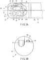
- FIG. 2A is a top view of a distal end constituting section including the swing base provided at a distal end of the insertion device, and
- FIG. 2B is a view showing an appearance constitution of the distal end constituting section seen from a front surface.
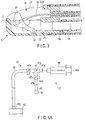
- FIG. 3 is a view showing a constitution of a transverse section of the swing base having an inverted state in the distal end constituting section shown in FIG. 2A .
- an endoscope apparatus 1 is mainly constituted of an insertion device 2 that is an endoscope main body, a light source device 3 that supplies illumination light to the insertion device 2, a control section 4 including a video processor that performs image processing to a video signal imaged by an unshown imaging unit disposed in a distal portion of the insertion device 2, a display section 5 that displays a photographed observation image and information on the image, a printing section 6 that prints the image information including the observation image displayed in the display section 5, and a recording section 7 that records the video signal.
- the medical endoscope apparatus is defined as one example of the insertion device, but does not have to be limited to this example.
- the insertion device 2 can be washed by a washing instrument of the present embodiment as long as the insertion device 2, for example, a catheter, an over tube or the like which does not have an industrial endoscope, an illumination optical system and an observation optical system, and has a constitution in which an aperture section or a region that is the washing target is inserted and removed from a peripheral surface side.
- a washing instrument of the present embodiment for example, a catheter, an over tube or the like which does not have an industrial endoscope, an illumination optical system and an observation optical system, and has a constitution in which an aperture section or a region that is the washing target is inserted and removed from a peripheral surface side.
- the insertion device 2 is mainly constituted of an inserting section 11 and an operating section 12.
- the inserting section 11 has a flexible tube portion 13 coupled with the operating section 12 and having flexibility, a bending portion 14 coupled with a distal end of the flexible tube portion 13, and a distal end constituting section 15 provided at a distal end of the bending portion 14 to receive the swing base.
- the operating section 12 is connected to the light source device 3 and the control section 4 by a universal cord 16.
- a forceps port 17 to introduce forceps or the like into the inserting section is interposed between a proximal portion of the inserting section 11 and the operating section 12.
- a node ring 14a of the bending portion 14 is fitted into the distal end constituting section 15 that is the distal portion of the insertion device, to couple the distal end constituting section with the bending portion 14.
- the distal end constituting section 15 is a laminated structure in which a main body portion 21 is made of a metal such as SUS, and further, a peripheral surface of the main body portion 21 is covered with a cover portion 22 having electric insulating properties.
- a part of an outer peripheral surface of the distal end constituting section 15 is flattened, and the flattened portion is divided into two sides in a longitudinal axis direction, and on one side, a stepped portion 25a is provided from the outer peripheral surface to form a flat observation surface 25, and on the other side, an aperture section 27 is formed.
- the observation surface 25 there are arranged an illumination window portion 23 to be irradiated with the illumination light and an observation window portion 24 including therein an unshown imaging element.
- a nozzle portion 26 is disposed from which a washing liquid such as saline jets outside, thereby suitably washing the illumination window portion 23 and the observation window portion 24.
- the observation surface 25 is a reference position (a reference surface) to an after-mentioned rotating direction regulating portion 42h.
- the aperture section 27 on the other side opens in a side peripheral surface of the distal end constituting section 15.
- a treatment instrument swing base hereinafter referred to as the swing base 31 is swingably disposed in a receiving chamber (or a swing base receiving chamber) 28 in the aperture section 27, a treatment instrument swing base (hereinafter referred to as the swing base) 31 is swingably disposed in a receiving chamber (or a swing base receiving chamber) 28 in the aperture section 27, a treatment instrument swing base (hereinafter referred to as the swing base) 31 is swingably disposed.
- Character C shown in FIG. 1 and FIG. 3 shows a direction in which the inserting section 11 and the distal end constituting section 15 are longitudinal, and indicates the longitudinal axis direction.
- the swing base 31 turns to be raised or inverted.
- the swing base 31 and its drive mechanism are arranged in the narrow receiving chamber 28, and hence it is hard to remove dirt due to a body fluid or a living tissue piece adhered to a region that is shade seen from the aperture section 27, e.g., a periphery of the raising shaft 32, a back surface of the swing base 31, or the like.
- the swing base 31 is not limited to the raising type, but may be a type of horizontally swinging a treatment instrument.
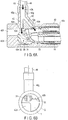
- FIG. 4A is a view showing an appearance constitution of the washing instrument of the present embodiment
- FIG. 4B is a view showing a state where the insertion device is attached to the washing instrument and washed
- FIG. 5 is a view of a washing instrument main body seen from a front side
- FIG. 6A is a view showing a transverse section of the washing instrument to which the insertion device is attached
- FIG. 6B is a view of the washing instrument to which the insertion device is attached and which is seen from the front side.
- a side into which the distal end constituting section 15 of the distal portion of the insertion device is inserted is defined as a rear side of the washing instrument, and a side on which a distal portion of the distal end constituting section 15 is defined as a front side.
- the washing instrument 41 of the present embodiment is roughly constituted of a washing instrument main body 42 and a liquid feed mechanism 43.
- the washing instrument main body 42 uses a transparent member and has a hollow receiving portion to which the distal end constituting section 15 is attached.
- the liquid feed mechanism 43 has an injection tube 49 coupled with a joint portion 42g of the washing instrument main body 42, a syringe coupling portion 47 coupled with the injection tube 49, a suction tube 48 extending from a branching liquid suction end 47d of the syringe coupling portion 47, a tubular weight 50 that prevents lift and also serves as a water suction port of the suction tube 48, and a syringe 46 of pumping means through which a washing fluid flows.
- the washing instrument 41 including the washing instrument main body 42 and mentioned below is prepared by using a transparent member.
- the use of the transparent member makes it easy to confirm a removal degree of the dirt from the outside.
- the injection tube 49 and the washing instrument main body 42 form an attachable/detachable structure, whereby when the washing instrument main body 42 is prepared in accordance with a shape of a distal portion of any insertion device, the washing instrument is usable as a washing instrument having high general-purpose properties.
- the syringe coupling portion 47 forms a T-shape branching in three ways, a storage chamber (a space to temporarily store a washing liquid 63) 47g is formed in the syringe coupling portion, the opening liquid suction end 47d and an opening liquid feed end 47e are provided in two of three end portions, and check valves 47b and 47c are disposed in the ends, respectively. Another end portion is a syringe attaching end 47a to be coupled with the syringe 46. A combination of the syringe 46 and the syringe coupling portion 47 functions as a pump.
- the check valves 47b and 47c may have a known structure in which a valve portion moves to close and open the flow channel, and may have, for example, a constitution in which a C-shaped slit is cut in a circular partition plate constituted of an elastic member so that the valve portion has a diameter larger than the flow channel.
- the check valve 47c adjusted into an opened state by turning the valve portion toward the outside when an inner pressure of a coupling portion main body is a positive pressure, and adjusted into a closed state by sucking the valve portion with a valve seat when the inner pressure is a negative pressure. Furthermore, in the liquid suction end 47d, there is provided the check valve 47b adjusted into an opened state by turning the valve portion inwardly when the inner pressure of the coupling portion main body is the negative pressure, and adjusted into a closed state by pressing the valve portion onto the valve seat when the inner pressure is the positive pressure.
- liquid feed means such as a liquid feed pump may be used.
- FIG. 4B shows a state of attaching the distal end constituting section 15 of the insertion device 2 to the washing instrument 41.
- the distal end constituting section 15 is positioned as described later and attached to the washing instrument main body 42 of the washing instrument 41, and the washing instrument is disposed in a drain tray 61.
- a liquid such as water is beforehand put in the drain tray 61, and the washing instrument main body 42 is sunk in the tray, so that in a case of discharging the washing liquid 63 from an opening 42f with great energy, it is possible to weaken the energy with the liquid and prevent the washing liquid from flying and scattering around the drain tray 61.
- a tray cover to prevent the flying and scattering may separately be prepared.
- the drain tray 61 is prepared by using the transparent member.
- the use of the transparent member makes it easy to confirm the removal degree of the dirt from the outside.
- its outer shape is cylindrical, but there is not any restriction on the outer shape as long as an inner shape is a hollow shape to which the distal end constituting section 15 is attachable, and the outer shape may be a rectangular box shape.
- a water suction port 50 of the suction tube 48 is disposed to sink in a suction water tray 62 filled with the washing liquid 63.
- the plunger 46a of the syringe 46 is pulled to pump up the washing liquid 63 in the suction water tray 62, thereby filling the storage chamber 47g of the syringe coupling portion 47 and the syringe 46.
- the plunger 46a is pushed to feed the washing liquid from the injection tube 49 to the washing instrument main body 42, and the washing liquid is supplied (here, jets out) from two after-mentioned washing ports at different angles, to wash the inside of the receiving chamber 28 including the swing base.
- the used washing liquid 63 is discharged together with adhered substances from the receiving chamber 28 through the opening (the opening 42 f shown in FIG. 6A ) to the drain tray 61. Furthermore, simultaneously, the washing liquid 63 flowing out from the receiving chamber 28 passes through an after-mentioned clearance while washing a peripheral portion of the distal end constituting section 15 attached to the washing instrument main body 42, and the washing liquid is discharged to the drain tray 61.
- the washing instrument main body 42 will be described with reference to FIGS. 6A and 6B .
- the washing instrument main body 42 of the present embodiment is a constitution in which one flow channel 42k in the joint portion 42g coupled with the injection tube 49 to become a supply receiving port of the washing liquid 63 branches into two flow channels 42i and 42j at the different angles in the main body and first and second washing ports 42a and 42b are arranged at distal ends of the respective flow channels.
- the washing liquid jets out from the first washing port 42a in a direction perpendicular to the longitudinal axis direction of the distal end constituting section 15. Furthermore, the washing liquid jets out from the second washing port 42b obliquely in a downward direction from a front side toward a rear side of a distal portion of the port. Needless to say, there is not any restriction on the directions in which the washing liquids jet out from the first and second washing ports 42a and 42b, and the directions may suitably be changed by design.
- an insertion port 42c to insert the distal end constituting section 15 is provided on the rear side
- an axial direction regulating portion 42d (a first movement regulating portion) abutting on the distal end constituting section 15 is provided on the front side, and in an upper portion of an inner peripheral surface, there are provided the rotating direction regulating portion 42h (a second movement regulating portion) facing the observation surface 25 of the distal end constituting section 15 described above, and the opening 42f to discharge the used washing liquid 63 to the outside.
- the axial direction regulating portion 42d and the rotating direction regulating portion 42h constitute the movement regulating portions, thereby positioning the distal end constituting section 15 at a predetermined attaching position in the washing instrument main body 42. It is to be noted that the attaching position is adjusted into a position at which the washing liquid 63 jetting out from the first and second washing ports 42a and 42b directly collides with a washing target region in the receiving chamber 28.
- drain water of the washing liquid 63 used in washing may be discharged through the clearance between the outer peripheral surface of the distal end constituting section 15 and the inner peripheral surface of the washing instrument main body 42, in addition to the opening 42f. Furthermore, in a case where a drain amount of the washing liquid 63 is large to such an extent that cannot be covered with the clearance, a drainable concave groove type of clearance (not shown) may be formed in a part of the inner peripheral surface along the inner peripheral surface in the longitudinal axis direction.
- the distal end constituting section 15 is inserted from the insertion port 42c into the washing instrument main body 42, and its distal end abuts on a positioning wall 42e of the axial direction regulating portion 42d while disposing the observation surface 25 to face the rotating direction regulating portion 42h, whereby the distal end constituting section 15 is positioned in an axial direction and a rotating direction.
- a distal portion of the swing base 31 rises to be positioned between the first washing port 42a and the second washing port 42b, and abuts on the inner peripheral surface of the washing instrument main body 42, to hold a positioned state.
- the distal portion of the swing base 31 is referred to as a holding portion to hold the positioned state, and the inner peripheral surface of the washing instrument main body 42 which abuts on this distal portion is referred to as a holding surface.
- This holding surface constitutes a swing base angle regulating portion set at an intermediate position between a position at which the swing base 31 completely falls and a position at which the swing base completely rises, to position the swing base 31.
- the washing instrument main body 42 is made of a transparent resin or the like, whereby even when the swing base 31 abuts on an upper inner surface of the washing instrument main body 42, the swing base 31 is not impaired.
- the washing port is provided at the distal end of each linear flow channel, and hence a constitution is illustrated in which the flow channel is disposed at an angle from a branching region, but there is not any special restriction on a flow channel route itself as long as the washing ports are provided to vary a jetting direction of the washing liquid 63 and a position reached by the washing liquid 63.
- diameters of the flow channels may be adjusted so that the diameters of the flow channels 42i and 42j decrease to taper off from the flow channel 42k of an inflow port to the first and second washing ports 42a and 42b, thereby increasing a jetting pressure of the jetting washing liquid 63.
- the first and second washing ports 42a and 42b narrow to function as nozzles, so that it is possible to increase the jetting pressure of the jetting washing liquid 63.
- the flow channel 42k branches into at least two flow channels 42i and 42j, and an optional inclination due to an angle difference is interposed between the flow channel 42i and the flow channel 42j in the axial direction to vary a liquid feed direction (a jetting angle) of the washing liquid 63 in the branching region.
- the first and second washing ports 42a and 42b are opened as respective flow channel distal ends via a space on the main body inner peripheral surface so that washing liquids 63a and 63b jet out into the receiving chamber 28 at different jetting angles from the aperture section 27 of the distal end constituting section 15 into the receiving chamber 28.
- the washing liquid 63a jets out from the first washing port 42a directly to the washing target region in a range from a back side of the surface of the receiving chamber 28 of the distal end constituting section 15 which comes in contact with a front side surface (the positioning wall 42e) through a bottom surface to a back surface side of the rising swing base 31. Furthermore, the washing liquid 63b jets out from the second washing port 42b directly toward a washing target region such as a rear side and the bottom surface of the receiving chamber 28, a periphery of the raising shaft 32 of the swing base 31, or the traction wire 33.
- washing liquids 63 jet out from the first washing port 42a and the second washing port 42b to the receiving chamber 28 of the distal end constituting section 15 in the directions both of which intersect the longitudinal axis of the insertion device 2 and which are different from each other (or at the different jetting angles).
- the washing instrument main body 42 is a constitution in which both front and rear ends are opened, and not only the opening 42 f of the distal end but also the clearance from the washing instrument main body 42 which is large as described above are disposed to the distal end constituting section 15 of an insertion device such as an endoscope, so that the used washing liquid 63 or filth is easy to flow outside.
- an insertion device such as an endoscope
- the state of positioning the distal end constituting section 15 of the insertion device 2 is held, and the washing liquids 63 jet out from the first washing port 42a and the second washing port 42b which are arranged away from each other to the receiving chamber 28 of the distal end constituting section 15 in the mutually different directions (or at the different jetting angles), so that the washing liquid 63 can directly jet out to various regions including the swing base 31 disposed in the receiving chamber 28 with respective high water feed forces, thereby performing the washing.
- the washing liquids 63 jetting out from the regions at the different angles not only directly collide with the washing target regions but also generate a complicated water flow in the receiving chamber 28, thereby achieving more effective washing. It is to be noted that the jetting angles from the washing ports which are present at different positions may be the same.
- the distal end constituting section 15 is tubularly covered, the washing liquids 63a and 63b jetting out from the first washing port 42a and the second washing port 42b collide with the inner peripheral surface (the wall surface) of a part of the washing instrument main body 42, and flow in the longitudinal axis direction to remain in the drain tray 61, and hence the washing liquid 63 does not directly spray over an operator.
- the washing instrument main body 42 sinks in water to perform the washing, thereby discharging the used washing liquid 63 into the water, and even when the distal end constituting section 15 comes out from the washing instrument main body 42, it is possible to prevent the used washing liquid 63 from flying and scattering to the outside.
- the injection tube 49 and the washing instrument main body 42 constitute the attachable/detachable structure, whereby when the washing instrument main body is only prepared in accordance with the shape of the distal portion of any insertion device, the washing instrument having high general-purpose properties is usable.
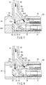
- FIG. 7 is a view showing a transverse section constitution of a washing instrument main body according to a second embodiment.
- the present embodiment is different from the above-mentioned first embodiment only in that a fixing system of a distal end constituting section 15, and the other constitutional region is equivalent to the above-mentioned first embodiment.
- a swing base 31 rises to bring a distal portion of the swing base 31 into contact with a flat inner peripheral surface of a washing instrument main body 42 which is a holding surface.
- an locking portion 52m of a convex shape is formed in a region of a holding surface of a washing instrument main body 42 to engage a raised distal portion of a swing base 31 with a corner of the locking portion.
- the corner of the locking portion 52m is formed between a first washing port 42a and a second washing port 42b, and has a projecting shape including the second washing port 42b.
- the distal portion of the swing base 31 rises to engage with this corner of the locking portion 52m, whereby the distal end constituting section 15 advances to press its distal surface onto a positioning wall 52e, thereby holding a positioned state of the distal end constituting section 15.
- the distal end constituting section 15 of an insertion device is inserted and positioned, and then the distal portion of the swing base 31 rises to engage with the locking portion 52m, thereby pressing and locking both sides of the locking portion 52m and the positioning wall 52e, so that it is possible to hold the positioned state of the distal end constituting section 15.
- FIG. 8 is a view showing an appearance constitution of a washing instrument main body for an insertion device according to a third embodiment.
- the present embodiment is a constitution in which there is changed a forming position of an axial direction regulating portion in the washing instrument main body of the above-mentioned first and second embodiments, and this axial direction regulating portion is also utilized as an locking portion in the above-mentioned second embodiment.
- Both front and rear sides of an axial direction regulating portion 65m of a washing instrument main body 65 are sandwiched between a cover portion 22a on a proximal side of an aperture section 27 of a distal end constituting section 15 and a distal portion of a swing base 31, thereby holding a positioned state.
- a constitution other than a holding region of the positioned state is equivalent to the above-mentioned second embodiment.
- the washing instrument main body 65 of the present embodiment forms a cylindrical shape opening forward and backward, and in its outer peripheral surface, a joint portion 65g coupled with an injection tube 49 is provided.
- One flow channel 65k in the joint portion 65g branches into two flow channels 65i and 65j at different angles in the main body, and at respective flow channel distal ends, first and second washing ports 65a and 65b are provided.
- the first and second washing ports 65a and 65b are provided to open in two regions via a space in a main body inner peripheral surface at the respective flow channel distal ends, so that washing liquids 63a and 63b jet out into a receiving chamber 28 at different jetting angles from the aperture section 27 of the distal end constituting section 15 into the receiving chamber.
- FIG. 8 illustrates an example in which the washing liquid 63a jetting out from the first washing port 65a jets out in a direction perpendicular to a longitudinal axis direction of the distal end constituting section 15.
- the axial direction regulating portion 65m of a projecting shape is provided to abut on the cover portion 22a on the proximal side of the aperture section 27, when the distal end constituting section 15 is inserted from an insertion port 65c.
- This providing position of the axial direction regulating portion 65m is a position at which the cover portion 22a abuts on a corner of a rear end of the axial direction regulating portion 65m, and is set so that the washing liquids 63a and 63b jet out to equivalent positions in the receiving chamber 28 at the same jetting angles (of the washing ports 65a and 65b in the present embodiment) as in the first and second washing ports 42a and 42b of the above-mentioned first embodiment.
- the axial direction regulating portion 65m moves inward from a front surface of the washing instrument main body 65, and hence a distal portion of the distal end constituting section 15 does not have to abut, so that it is possible to apply the washing instrument even to an insertion device that is not suitable for the abutment of the distal portion.
- the axial direction regulating portion 65m is positioned by bringing its corner on the rear side into contact with the cover portion 22a on the proximal side of the aperture section 27 of an insertion device 2, and furthermore, the axial direction regulating portion 65m is sandwiched by attaching its corner on the front side to the raised distal portion of the swing base 31, so that it is possible to hold a positioned state of the distal portion of the distal end constituting section 15.
- the whole front surface of the washing instrument main body 52 becomes an opening to discharge the washing liquid 63, and hence it is possible to also cope with increase of an amount of the washing liquid 63 to be discharged.
- FIG. 9 is a view showing a transverse section of a washing instrument main body to which an insertion device is attached according to a fourth embodiment.
- the present embodiment is a constitution to hold a positioned state of a distal portion of a distal end constituting section 15 by a pressure of a washing liquid 63 jetting out from first and second washing ports of the washing instrument main body.
- a constitution other than flow channels 72i and 72j and first and second washing ports 72a and 72b of the washing instrument main body is equivalent to the above-mentioned first embodiment.
- a washing instrument main body 72 of the present embodiment is a constitution in which one flow channel 72k in a joint portion 72g coupled with an injection tube 49 to become a supply receiving port of the washing liquid 63 branches into two flow channels 72i and 72j at different angles in the main body, to feed the liquid to each of the first and second washing ports 72a and 72b.
- the flow channel 72i extends obliquely downward from a rear side toward a front side at an acute angle set to an angle ⁇ 1
- the flow channel 72j similarly extends obliquely downward from the rear side toward the front side at the acute angle set to an angle ⁇ 1 which is larger than the angle ⁇ 1 (wherein the angle is smaller than 90 degrees) .
- a direction in which a washing liquid 63a jets out from the first washing port 72a and a longitudinal axis direction of the flow channel 72i are present on the same axis, and a jetting angle is identical to the angle ⁇ 1.
- a direction in which a washing liquid 63b jets out from the second washing port 72b and a longitudinal axis direction of the flow channel 72j are present on the same axis, and a jetting angle is identical to the angle ⁇ 1.
- the washing liquid 63a jetting out from the first washing port 72a directly sprays on a range from a front side surface and a bottom surface of the receiving chamber 28 to a back surface side of a swing base 31 to perform the washing.
- washing liquid 63a jetting out from the second washing port 72b directly sprays on a raised surface of the swing base 31, a rear side and the bottom surface of the receiving chamber 28, a periphery of a raising shaft 32 of the swing base 31, an attaching region of a traction wire 33, and the like to perform the washing.
- pressures due to the jetting washing liquids 63a and 63b act in a direction to press the receiving chamber 28 of the distal end constituting section 15 onto an axial direction regulating portion 72d, to hold a positioned state of the distal portion of the distal end constituting section 15.
- a direction in which the pressure due to the washing liquid 63b acts (the angle ⁇ 1) has an angle larger than a direction in which the pressure due to the washing liquid 63a acts (the angle ⁇ 1). That is, the washing liquids 63a and 63b jet out at the different angles, whereby the pressure due to the washing liquid 63a has a high ratio of a force that acts in a direction to press the receiving chamber 28 onto the axial direction regulating portion 72d, and the pressure due to the washing liquid 63b has a high ratio of a force that acts in a direction to press the receiving chamber 28 onto an inner peripheral surface side of the washing instrument main body.
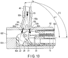
- FIG. 10 is a view showing a transverse section of a washing instrument main body to which an insertion device is attached according to a fifth embodiment.
- the present embodiment is a constitution to hold a positioned state of a distal portion of a distal end constituting section 15 by a water feed force (a pressure) of a washing liquid 63 jetting out from first and second washing ports of the washing instrument main body.
- a constitution other than flow channels 82i and 82 j and first and second washing ports 82a and 82b of the washing instrument main body is equivalent to the above-mentioned first embodiment.
- a washing instrument main body 82 of the present embodiment is a constitution in which one flow channel 82k in a joint portion 82g which becomes a supply receiving port of the washing liquid 63 branches into two flow channels 82i and 82j at different angles in the main body, to feed the liquid to each of the first and second washing ports 82a and 82b.
- a sectional area of a diameter of the flow channel 82i is set to be larger than a sectional area of a diameter of the flow channel 82j, and an amount of the washing liquid jetting out from the first washing port 82a per hour [a first water feed amount] is set to be larger than an amount of the washing liquid jetting out from the second washing port 82b [a second water feed amount] so that a water feed force of the washing liquid 63a is larger than that of the washing liquid 63b.
- the flow channel 82i extends obliquely downward from a rear side toward a front side at an acute angle (the angle from the rear side of a longitudinal axis) set to an angle ⁇ 2.
- the flow channel 82j extends obliquely downward from the front side toward the rear side at an acute angle set to an angle ⁇ 2 (90 degrees or more).
- the branched flow channel 82i and flow channel 82j have an angle difference ( ⁇ - ⁇ ).
- the washing liquids 63a and 63b jetting out from the first and second washing ports 82a and 82b directly collide with washing target regions of a receiving chamber 28 of the distal end constituting section 15, to perform washing. That is, the washing liquid 63a jetting out from the first washing port 82a directly sprays on a range from a front side surface and a bottom surface of the receiving chamber 28 to a back surface side of a swing base 31 to perform the washing. Furthermore, the washing liquid 63b jetting out from the second washing port 82b directly sprays on the bottom surface of the receiving chamber 28 on a rear side, a periphery of a raising shaft 32 of the swing base 31, an attaching region of a traction wire 33, and the like to perform the washing.
- a pressure due to a difference in water feed force between the jetting washing liquid 63a and the jetting washing liquid 63b acts in a direction to press the receiving chamber 28 of the distal end constituting section 15 onto an axial direction regulating portion 82d, thereby making it possible to hold a positioned state of the distal portion of the distal end constituting section 15.
- amounts of the washing liquids jetting out from the first and second washing ports 82a and 82b (the sectional areas of the diameters) and directions in which the washing liquids 63a and 63b jet outside are suitably changed by design.
- each including two washing ports there have been described examples each including two washing ports, but the number of the washing ports may be one or three or more as long as it is possible to hold the positioned state of the distal end constituting section 15 by the pressure of the water feed force and to sufficiently wash the inside of the receiving chamber.
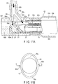
- FIG. 11A is a view showing a transverse section of a washing instrument main body to which an insertion device is attached according to a sixth embodiment
- FIG. 11B is a conceptual view of the washing instrument main body seen from a rear side.
- the present embodiment is a constitutional example including a holding member 93 holding a positioned state of a distal end constituting section 15 of the insertion device attached to a washing instrument main body 92.
- a constitution other than the holding member is equivalent to the above-mentioned first embodiment.
- the holding member 93 of a tubular shape which sandwiches the attached distal end constituting section 15 from both right and left sides is fitted into and attached to the rear side of the washing instrument main body 92.
- the holding member 93 uses an elastic member and is constituted of a cylindrical portion 93a fitted into an attaching portion 92n including a rear side stepped portion of the washing instrument main body 92, and a holding portion 93b in which an opening surface has an elliptic shape through a stepped portion tapering and extending from the cylindrical portion 93a.
- the holding portion 93b sandwiches the distal end constituting section 15 from both the right and left sides with an elastic force that works in an n-direction from both the sides of a narrowed side (a region of arrows 93b of FIG. 11B ), and holds the distal end constituting section 15 in the positioned state of the above-mentioned embodiment. Furthermore, crescent-shaped voids 93c generated on and under the distal end constituting section 15 in the holding portion 93b of the elliptic shape shown in FIG. 11B are utilized as discharge paths of a washing liquid 63.
- the distal end constituting section 15 positioned and attached to the washing instrument main body 92 is sandwiched by the holding member 93 to hold the positioned state.
- the jetting washing liquid 63 directly collides with a washing target region to perform the washing.
- the washing liquid 63 after the washing passes a clearance from the washing instrument main body 92 to be discharged from the voids 93c of the holding member 93.
- the washing instrument main body 84 sinks in water to perform washing, thereby discharging the used washing liquid 63 into the water, and even when the distal end constituting section 15 comes out from the washing instrument main body 84, it is possible to prevent the used washing liquid 63 from flying and scattering to the outside.
- FIG. 12 is a view showing an appearance constitution of a syringe for use in a washing instrument according to a seventh embodiment
- FIG. 13A is a view showing a transverse section of a washing instrument main body to which an insertion device is attached
- FIG. 13B is a view of the washing instrument main body to which the insertion device is attached and which is seen from a front side
- FIG. 14 is a view showing a state where the insertion device is attached to the washing instrument and washed.
- the present embodiment uses a syringe 46 and a tapered nozzle 94 shown in FIG. 12 in place of the above-mentioned liquid feed mechanism constituted of the injection tube, the syringe coupling portion, the syringe and the suction tube.
- the washing instrument of the present embodiment is constituted of a washing instrument main body 101 having a receiving portion forming therein a hollow of a cylindrical shape, and a liquid feed mechanism comprising the syringe 46 and the tapered nozzle 94 which supply a washing liquid 63.
- the washing instrument main body 101 has joint portions 101g and 101h into which the tapered nozzle 94 is attachably/detachably inserted and which become supply receiving ports of the washing liquid 63, guide bores 101i and 101j formed in the joint portions 101g and 101h to match an outer shape of the tapered nozzle 94, and openings 101a and 101b through each of which a distal end of the tapered nozzle 94 projects from each of the guide bores 101i and 101j into the washing instrument main body 101.
- an insertion port 101c to insert a distal end constituting section 15 is provided on its rear side
- an axial direction regulating portion 101d abutting on the distal end constituting section 15 is provided on its front side, and in an upper portion of an inner peripheral surface, there are provided a rotating direction regulating portion 101m facing an observation surface 25 of the distal end constituting section 15, and an opening 101f to discharge the used washing liquids 63 (63a and 63b) to the outside.
- the axial direction regulating portion 101d and the rotating direction regulating portion 101m constitute movement regulating portions, to position the distal end constituting section 15 at a predetermined attaching position in the washing instrument main body 101.
- the joint portions 101g and 101h are set at an angle y (an obtuse angle) to a longitudinal axis of the washing instrument main body 101 from a rear side, to pour the washing liquids 63 in parallel from an obliquely upper front to an obliquely lower rear.
- a swing base 31 in a receiving chamber 28 rises to bring its distal portion into contact with the inner peripheral surface of the washing instrument main body 101, and holds the positioned distal end constituting section 15.
- an opening size is set so that the inserted distal end of the tapered nozzle 94 projects to a position passing a back surface side of the raised swing base 31 and reaches a position at which the washing liquid 63 directly collides with a bottom surface in the receiving chamber 28.
- an opening size is set so that the inserted distal end of the tapered nozzle 94 projects to a position just before a traction wire 33 of the swing base 31 and reaches a position at which the washing liquid 63 directly collides with a periphery of a raising shaft 32 and its peripheral portion in the receiving chamber 28.
- an angle of the guide bore 101i to hold the tapered nozzle 94 is set so that the washing liquid 63a can jet out vertically into the receiving chamber 28. Furthermore, in the joint portion 101h for the washing liquid 63 into the receiving chamber 28, an angle of the guide bore 101j to hold the tapered nozzle 94 is set to a vertically inclined angle so that the jetting washing liquid 63 turns in the receiving chamber.
- the distal end constituting section 15 is positioned and attached to the washing instrument main body 101, and the washing instrument main body is disposed in a drain tray 61. At this time, when a liquid such as water is beforehand put in the drain tray 61 and the washing instrument main body 101 is sunk, energy of the washing liquid 63 discharged from the washing instrument main body 101 weakens, thereby making it possible to prevent the washing liquid from flying and scattering around the drain tray 61.
- the distal end of the tapered nozzle 94 is placed in the washing liquid 63 stored in a container, and a plunger 46a is pulled to suck the washing liquid 63, thereby storing the liquid in the syringe 46.
- the tapered nozzle 94 is inserted from an opening of the guide bore 101i of the joint portion 101g until abutting and is attached.
- the joint portion 101h is hermetically sealed with a leak preventing cap 95 to tightly close an opening of the other guide bore 101j. This hermetic seal is used to prevent the washing liquid 63 from flowing backward to the guide bore 101j and leaking out from the joint portion 101h, when the washing liquid is poured from the joint portion 101g.
- the plunger 46a is pushed into the syringe 46, and the received washing liquid 63 jets out from the distal end of the tapered nozzle 94 into the receiving chamber 28 with great energy.
- the jetting washing liquid 63a directly collides with the back surface side of the swing base 31 in the receiving chamber 28 and the bottom surface of the receiving chamber 28 to perform washing.
- the washing liquid 63a turns to a front side (a raised upper surface side) of the swing base 31, the periphery of the raising shaft 32, an attaching region of the traction wire 33 or the like to perform the washing.
- the washing liquid 63a after the washing flows out from the opening 101f and a clearance between the distal end constituting section 15 and the washing instrument main body 101, and is discharged into the drain tray 61. It is to be noted that when flowing out from the clearance, the washing liquid 63a is discharged to the drain tray 61 while washing a peripheral portion of the distal end constituting section 15.
- the syringe 46 is extracted from the joint portion 101g, and the leak preventing cap 95 is moved from the joint portion 101h to the joint portion 101g to perform the hermetic sealing.
- the new washing liquid 63 is sucked and received in the syringe 46, and then the tapered nozzle 94 is inserted into the joint portion 101h.
- the plunger 46a is pushed into the syringe 46, and the washing liquid 63b jets out from the distal end of the tapered nozzle 94 into the receiving chamber 28 with great energy.
- the jetting washing liquid 63b directly collides with the front side (the raised surface side) of the swing base 31 in the receiving chamber 28, the periphery of the raising shaft 32, the attaching region of the traction wire 33 or the like to perform the washing. Furthermore, at this time, the washing liquid 63b turns to the back surface side of the swing base 31 to perform the washing.
- the washing liquid 63b after the washing flows out from the opening 101f and the clearance and is discharged into the drain tray 61 in the same manner as in the washing liquid 63a. It is to be noted that when flowing out from the clearance, the washing liquid 63b is discharged to the drain tray 61 while washing the peripheral portion of the distal end constituting section 15.
- a space between the joint portion 101g and the joint portion 101h is formed as a space via which two syringes are simultaneously attached, and the two syringes are attached, so that it is also possible to alternately or simultaneously push the plungers, thereby performing the washing.
- two operators push the plungers when the two plungers are not present in a range that is reachable with one hand or when the syringe 46 is not fixed to the drain tray 61.
- the distal end of the attached tapered nozzle 94 easily reaches the region just before the washing target region, and hence with the washing liquids 63a and 63b jetting out from the tapered nozzle 94, it is possible to strongly wash the back side of the swing base 31, the periphery of the raising shaft 32, the attaching region of the traction wire 33, or the like.
- the washing instrument is only constituted of the washing instrument main body 101 and the syringe 46, and can be achieved at low cost.
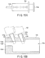
- FIG. 15A is a view showing an appearance constitution of a syringe for use in a washing instrument according to an eighth embodiment
- FIG. 15B is a view showing a transverse section of a washing instrument main body to which the syringe is attached.
- the present embodiment is an example in which the present embodiment is only constituted of a syringe, but in the above-mentioned seventh embodiment, a liquid feed mechanism of a washing liquid is constituted of a combination of the syringe 46 and the tapered nozzle 94.
- a syringe 102 shown in FIG. 15A is constituted of a plunger 102a, and a tube main body (an injection tube) to which a comparatively short tapered distal portion 102b is integrally attached.
- a washing instrument main body 103 is a constitution equivalent to the washing instrument main body 101 in the above-mentioned seventh embodiment, and guide bores 103i and 103 j of joint portions 103g and 103h are formed to match an outer shape of the distal portion 102b of the syringe 46.
- washing instrument for an insertion device which holds the insertion device attached to a predetermined position of a washing instrument main body and in which washing liquids directly jet out to washing target regions from different directions to perform washing.
Landscapes
- Health & Medical Sciences (AREA)
- Life Sciences & Earth Sciences (AREA)
- Surgery (AREA)
- Engineering & Computer Science (AREA)
- Biomedical Technology (AREA)
- Molecular Biology (AREA)
- Pathology (AREA)
- Radiology & Medical Imaging (AREA)
- Nuclear Medicine, Radiotherapy & Molecular Imaging (AREA)
- Biophysics (AREA)
- Physics & Mathematics (AREA)
- Heart & Thoracic Surgery (AREA)
- Medical Informatics (AREA)
- Optics & Photonics (AREA)
- Animal Behavior & Ethology (AREA)
- General Health & Medical Sciences (AREA)
- Public Health (AREA)
- Veterinary Medicine (AREA)
- Mechanical Engineering (AREA)
- Endoscopes (AREA)
- Instruments For Viewing The Inside Of Hollow Bodies (AREA)
- Cleaning By Liquid Or Steam (AREA)
Applications Claiming Priority (2)
| Application Number | Priority Date | Filing Date | Title |
|---|---|---|---|
| JP2014210879 | 2014-10-15 | ||
| PCT/JP2015/075910 WO2016059920A1 (fr) | 2014-10-15 | 2015-09-11 | Accessoire de nettoyage à dispositif d'insertion |
Publications (2)
| Publication Number | Publication Date |
|---|---|
| EP3207858A1 true EP3207858A1 (fr) | 2017-08-23 |
| EP3207858A4 EP3207858A4 (fr) | 2018-10-24 |
Family
ID=55746468
Family Applications (1)
| Application Number | Title | Priority Date | Filing Date |
|---|---|---|---|
| EP15850455.5A Withdrawn EP3207858A4 (fr) | 2014-10-15 | 2015-09-11 | Accessoire de nettoyage à dispositif d'insertion |
Country Status (5)
| Country | Link |
|---|---|
| US (1) | US9993145B2 (fr) |
| EP (1) | EP3207858A4 (fr) |
| JP (1) | JP6001215B2 (fr) |
| CN (1) | CN106455962B (fr) |
| WO (1) | WO2016059920A1 (fr) |
Cited By (3)
| Publication number | Priority date | Publication date | Assignee | Title |
|---|---|---|---|---|
| EP3384823A4 (fr) * | 2016-04-25 | 2019-07-31 | Olympus Corporation | Dispositif de retraitement d'endoscope |
| US11490799B2 (en) | 2018-01-31 | 2022-11-08 | Olympus Corporation | Cleaning tool for insertion device |
| US12064094B2 (en) | 2018-06-28 | 2024-08-20 | Olympus Corporation | Endoscope cleaning instrument |
Families Citing this family (10)
| Publication number | Priority date | Publication date | Assignee | Title |
|---|---|---|---|---|
| WO2017187919A1 (fr) | 2016-04-25 | 2017-11-02 | オリンパス株式会社 | Dispositif de retraitement d'endoscope |
| CN109475287B (zh) | 2016-07-19 | 2021-09-21 | 奥林巴斯株式会社 | 内窥镜用顶端附件 |
| CN106821285B (zh) * | 2017-02-08 | 2019-02-26 | 深圳开立生物医疗科技股份有限公司 | 一种可消除消毒死角的内窥镜头座与内窥镜 |
| JP6401423B1 (ja) * | 2017-03-09 | 2018-10-10 | オリンパス株式会社 | 内視鏡システムおよび内視鏡のリーク検知処理方法 |
| JP6871431B2 (ja) * | 2018-01-31 | 2021-05-12 | オリンパス株式会社 | 挿入器具用洗浄具 |
| CN109513697B (zh) * | 2018-11-19 | 2021-12-10 | 中国通信建设第一工程局有限公司 | 通信管道管孔堵塞点铣削装置 |
| JP7339695B2 (ja) * | 2019-07-08 | 2023-09-06 | 株式会社アダチメディカルレンタルリース | 内視鏡の洗浄に用いられるスプレー容器及びこれに用いる挿込アダプタ |
| US11986361B2 (en) * | 2020-11-17 | 2024-05-21 | Virginia Commonwealth University | Stent retriever cleaning devices and methods |
| CN119451640B (zh) * | 2022-06-30 | 2025-10-10 | 瑞德医疗机器股份有限公司 | 用于清洗手术器械的清洗用器械 |
| WO2024246706A1 (fr) * | 2023-05-26 | 2024-12-05 | Saban Ventures Pty Limited | Caractérisation de l'efficacité d'un nettoyage de canal |
Family Cites Families (14)
| Publication number | Priority date | Publication date | Assignee | Title |
|---|---|---|---|---|
| JPS58133230A (ja) * | 1982-02-02 | 1983-08-08 | オリンパス光学工業株式会社 | 内視鏡におけるワイヤ案内管の洗浄装置 |
| US4683874A (en) * | 1986-02-07 | 1987-08-04 | Angelo Acquista | Bronchofiberscope |
| JPH04314418A (ja) * | 1991-04-12 | 1992-11-05 | Olympus Optical Co Ltd | 内視鏡洗浄消毒装置 |
| DE4425015C2 (de) * | 1994-07-15 | 1997-01-16 | Winter & Ibe Olympus | Endoskopisches HF-chirurgisches Gerät |
| JP3093932B2 (ja) * | 1994-09-07 | 2000-10-03 | 富士写真光機株式会社 | 内視鏡先端部 |
| JPH08196505A (ja) * | 1995-01-30 | 1996-08-06 | Olympus Optical Co Ltd | 内視鏡用管路切換え装置 |
| JP2004105284A (ja) * | 2002-09-13 | 2004-04-08 | Olympus Corp | 外科用処置具の洗浄装置 |
| JP4461100B2 (ja) * | 2004-02-16 | 2010-05-12 | オリンパス株式会社 | 内視鏡システム |
| CN100531809C (zh) * | 2004-03-05 | 2009-08-26 | 未来医学系统有限公司 | 用于内窥镜检查的冲洗或吸出机的盒 |
| JP4763307B2 (ja) * | 2005-02-18 | 2011-08-31 | オリンパス株式会社 | 内視鏡用処置具 |
| JP5220435B2 (ja) * | 2008-02-20 | 2013-06-26 | オリンパスメディカルシステムズ株式会社 | 洗浄チューブ、及び内視鏡洗浄消毒装置 |
| JP5153476B2 (ja) * | 2008-06-24 | 2013-02-27 | オリンパスメディカルシステムズ株式会社 | 内視鏡装置 |
| JP5437200B2 (ja) * | 2010-08-30 | 2014-03-12 | 富士フイルム株式会社 | 硬性内視鏡及びその作動方法 |
| WO2015107801A1 (fr) * | 2014-01-15 | 2015-07-23 | オリンパスメディカルシステムズ株式会社 | Outil de lavage et dispositif de lavage/désinfection d'endoscope |
-
2015
- 2015-09-11 JP JP2016524549A patent/JP6001215B2/ja active Active
- 2015-09-11 WO PCT/JP2015/075910 patent/WO2016059920A1/fr not_active Ceased
- 2015-09-11 EP EP15850455.5A patent/EP3207858A4/fr not_active Withdrawn
- 2015-09-11 CN CN201580027917.3A patent/CN106455962B/zh active Active
-
2017
- 2017-03-13 US US15/456,806 patent/US9993145B2/en active Active
Cited By (3)
| Publication number | Priority date | Publication date | Assignee | Title |
|---|---|---|---|---|
| EP3384823A4 (fr) * | 2016-04-25 | 2019-07-31 | Olympus Corporation | Dispositif de retraitement d'endoscope |
| US11490799B2 (en) | 2018-01-31 | 2022-11-08 | Olympus Corporation | Cleaning tool for insertion device |
| US12064094B2 (en) | 2018-06-28 | 2024-08-20 | Olympus Corporation | Endoscope cleaning instrument |
Also Published As
| Publication number | Publication date |
|---|---|
| US20170181611A1 (en) | 2017-06-29 |
| EP3207858A4 (fr) | 2018-10-24 |
| US9993145B2 (en) | 2018-06-12 |
| JP6001215B2 (ja) | 2016-10-05 |
| WO2016059920A1 (fr) | 2016-04-21 |
| CN106455962B (zh) | 2018-12-28 |
| CN106455962A (zh) | 2017-02-22 |
| JPWO2016059920A1 (ja) | 2017-04-27 |
Similar Documents
| Publication | Publication Date | Title |
|---|---|---|
| US9993145B2 (en) | Washing instrument for insertion device | |
| US10004390B2 (en) | Washing tool for insertion device | |
| RU2474436C2 (ru) | Узел дренажного насоса | |
| US20220192479A1 (en) | Tubing assemblies and methods for fluid delivery | |
| US10920767B2 (en) | Ophthalmic lubrication system and associated apparatus, systems, and methods | |
| US5048508A (en) | Endoscope having sealed shaft | |
| EP3207860A1 (fr) | Accessoire de nettoyage de dispositif d'insertion | |
| JP2010511481A (ja) | 内視鏡ポンプのための装置及び方法 | |
| CN104434005B (zh) | 一种内窥镜流体控制阀及流体控制系统 | |
| EP2574272B1 (fr) | Bouchon de forceps endoscopique | |
| JP7098841B2 (ja) | 内視鏡用先端カバー、内視鏡装置 | |
| US20170079514A1 (en) | Fluid plug unit and insertion device | |
| EP2633800A1 (fr) | Bouteille chimique pour dispositif de nettoyage/désinfection d'endoscope, et dispositif de nettoyage/désinfection d'endoscope | |
| JP2015177914A (ja) | 洗浄装置 | |
| WO2021205649A1 (fr) | Système de gaine pour endoscope et gaine pour endoscope | |
| JP2005211453A (ja) | 内視鏡 | |
| JP2003284675A (ja) | カバー式内視鏡 | |
| RU125446U1 (ru) | Устройство управления текучими средами в эндоскопе | |
| JP6013658B2 (ja) | 洗浄システム及び洗浄方法 | |
| RU2523354C2 (ru) | Устройство управления текучими средами в эндоскопе и эндоскоп | |
| JPS5910963Y2 (ja) | 内視鏡用送液装置 | |
| JP2025542271A (ja) | 気水チューブ端部コネクタのサイフォン保護及び感染防止 | |
| EP4523602A1 (fr) | Procédé et agencement pour le pré-nettoyage d'un endoscope | |
| JP2018126237A (ja) | 内視鏡装置 | |
| JP2006081756A (ja) | 内視鏡の吸引制御装置 |
Legal Events
| Date | Code | Title | Description |
|---|---|---|---|
| STAA | Information on the status of an ep patent application or granted ep patent |
Free format text: STATUS: THE INTERNATIONAL PUBLICATION HAS BEEN MADE |
|
| PUAI | Public reference made under article 153(3) epc to a published international application that has entered the european phase |
Free format text: ORIGINAL CODE: 0009012 |
|
| STAA | Information on the status of an ep patent application or granted ep patent |
Free format text: STATUS: REQUEST FOR EXAMINATION WAS MADE |
|
| 17P | Request for examination filed |
Effective date: 20170505 |
|
| AK | Designated contracting states |
Kind code of ref document: A1 Designated state(s): AL AT BE BG CH CY CZ DE DK EE ES FI FR GB GR HR HU IE IS IT LI LT LU LV MC MK MT NL NO PL PT RO RS SE SI SK SM TR |
|
| AX | Request for extension of the european patent |
Extension state: BA ME |
|
| DAV | Request for validation of the european patent (deleted) | ||
| DAX | Request for extension of the european patent (deleted) | ||
| RIC1 | Information provided on ipc code assigned before grant |
Ipc: A61B 1/12 20060101AFI20180613BHEP Ipc: A61B 1/00 20060101ALI20180613BHEP |
|
| A4 | Supplementary search report drawn up and despatched |
Effective date: 20180925 |
|
| RIC1 | Information provided on ipc code assigned before grant |
Ipc: A61B 1/00 20060101ALI20180919BHEP Ipc: A61B 1/12 20060101AFI20180919BHEP |
|
| STAA | Information on the status of an ep patent application or granted ep patent |
Free format text: STATUS: THE APPLICATION IS DEEMED TO BE WITHDRAWN |
|
| 18D | Application deemed to be withdrawn |
Effective date: 20190402 |