EP3208399B1 - Vorrichtung zum verankern einer verkleidungsmauer an einer tragenden mauer - Google Patents
Vorrichtung zum verankern einer verkleidungsmauer an einer tragenden mauer Download PDFInfo
- Publication number
- EP3208399B1 EP3208399B1 EP17154565.0A EP17154565A EP3208399B1 EP 3208399 B1 EP3208399 B1 EP 3208399B1 EP 17154565 A EP17154565 A EP 17154565A EP 3208399 B1 EP3208399 B1 EP 3208399B1
- Authority
- EP
- European Patent Office
- Prior art keywords
- anchor
- spacer
- wall
- anchoring
- housing
- Prior art date
- Legal status (The legal status is an assumption and is not a legal conclusion. Google has not performed a legal analysis and makes no representation as to the accuracy of the status listed.)
- Active
Links
Images

Classifications
-
- E—FIXED CONSTRUCTIONS
- E04—BUILDING
- E04B—GENERAL BUILDING CONSTRUCTIONS; WALLS, e.g. PARTITIONS; ROOFS; FLOORS; CEILINGS; INSULATION OR OTHER PROTECTION OF BUILDINGS
- E04B2/00—Walls, e.g. partitions, for buildings; Wall construction with regard to insulation; Connections specially adapted to walls
- E04B2/02—Walls, e.g. partitions, for buildings; Wall construction with regard to insulation; Connections specially adapted to walls built-up from layers of building elements
- E04B2/28—Walls having cavities between, but not in, the elements; Walls of elements each consisting of two or more parts kept in distance by means of spacers, all parts being solid
- E04B2/30—Walls having cavities between, but not in, the elements; Walls of elements each consisting of two or more parts kept in distance by means of spacers, all parts being solid using elements having specially designed means for stabilising the position; Spacers for cavity walls
-
- E—FIXED CONSTRUCTIONS
- E04—BUILDING
- E04B—GENERAL BUILDING CONSTRUCTIONS; WALLS, e.g. PARTITIONS; ROOFS; FLOORS; CEILINGS; INSULATION OR OTHER PROTECTION OF BUILDINGS
- E04B1/00—Constructions in general; Structures which are not restricted either to walls, e.g. partitions, or floors or ceilings or roofs
- E04B1/38—Connections for building structures in general
- E04B1/41—Connecting devices specially adapted for embedding in concrete or masonry
- E04B1/4178—Masonry wall ties
Definitions
- the present invention relates to the field of doubling external walls of buildings, especially in the case of a double wall, that is to say a case where a load-bearing wall is lined with a brick wall, these walls being separated from an empty space or filled with thermal insulation.
- Such brick walls generally serve as cladding for the exterior walls of a building.
- the invention relates more particularly to walls built without mortar.
- the document EP2831347 describes such a method.
- Such a brick wall is generally not self-stable, especially if it is high, for example on several floors; it must be anchored in the load-bearing wall.
- the documents WO2016023804A , US1548214A described a device for anchoring a wall with a load-bearing wall.
- the invention aims to provide a device for anchoring such a brick wall assembled without mortar with a load-bearing wall.
- the first anchorage housing may be a "T" shaped groove, preferably vertical, opening through a narrow zone on a front face of the load-bearing wall and comprising an enlarged zone, at the rear of the narrow zone, the anchor comprising a body being able to assume a first position in which it can be introduced into the widened zone through the narrow zone and a second position, in which it is a prisoner of the enlarged zone.
- the anchor is in a bent jail, the body having a shape of "C” and this anchor further comprising two lugs extending in opposite relation to each other, each from a respective edge "C", the tabs comprising means for attaching the first end of the spacer.
- These fixing means of the first end of the spacer comprise two holes, each formed vis-à-vis the other in a respective tab, at a distance from the edge, the tabs being provided to be elastically approximated one of the other, so that, when the holes are substantially coaxial, the first end of the spacer can be introduced therein, the anchor being designed so that said tabs tend to move elastically away from each other until the edges of the holes are arched on the first end of the spacer, the spacer and the anchor thus being held in mutual engagement.
- the spacer is advantageously formed from a substantially constant section wire, preferably of circular section.
- the invention also relates to a method of construction using an anchoring device according to the invention.
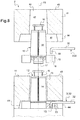
- a double wall comprises a load-bearing wall 1, a doubling wall 2 and a device 3 for anchoring the lining 2 on the load-bearing wall 1.
- the bearing wall 1 comprises blocks 4 of agglomerated concrete nested within each other.
- a block 4 is partially represented in Figures 1, 2 and 4 .
- This block 4 comprises, over its entire height, a vertical groove 6 of substantially constant section "T".
- the groove 6 is open on a front face 7 of the block 4, vis-à-vis the lining 2. Since the front face 7, the groove comprises a narrow zone 61 of substantially constant width L61 which extends rearwardly over a distance D61, to an enlarged zone, of width L62, and of depth D62.
- the doubling 2 consists of a stack of bricks 11 and inserts 12, substantially symmetrical with respect to a vertical plane P2 perpendicular to the plane of figures 1 and 5 .
- the bricks 11 are terracotta and the inserts 12 are made of a plastic material.
- Each insert 12 is provided to snap onto an insert disposed below it, then to be dressed by a brick 11 of the liner 2.
- the inserts, fitted together, form a frame for the lining 2, the bricks constituting a dressing for this framework.
- Each insert comprises a base 13 and two spurs 14, extending vertically upwards, from the base 13. For each insert 12, only one of the spurs is visible, the other being hidden by the one that is visible.
- the top of each spur 14 comprises first catch means 16 and under each spur are arranged second catch means 17.
- the first catch means 16 of an insert 12 are provided to snap into the second catch means 17 of an insert disposed immediately above.
- the inserts are arranged staggered, that is to say that on the same insert of a row of lower bricks, are snapped two inserts an upper row of bricks, each of the two inserts of the upper row engaging a respective spur of the insert of the lower row.
- Each insert comprises a row of vertical cylindrical housings 18 arranged in two horizontal rows parallel to the plane of symmetry P2.
- the anchoring device 3 comprises a reed 21 and a cross-rod-shaped interlock 22.
- the anchor is made of folded sheet, symmetrically relative to a plane P21H; it is also symmetrical relative to a plane P21V, perpendicular to the plane P21H, to the figure 1 , the plane P21V is confused with the plane of the figure.
- the anchor comprises a body 23 and two ends extending from the body, in the form of tabs 24 facing each other, on either side of the plane of symmetry P21H.
- the body has a section, in the substantially rectangular plane P21V, shaped "C", each of the tabs 24 extending from a respective edge 26 of the "C".
- Each of the tabs 24 is pierced with a through hole 27, vis-à-vis the hole of the other leg, at a distance from the respective edge 26.
- the body 23 has a thickness E23, measured parallel to the two planes of symmetry P21H and P21V, less than the depth D62 of the enlarged area 62 of the groove 6 (E23 ⁇ D62).
- the body furthermore has a width L23, measured perpendicularly to the plane P21V, smaller than the width L62 of the enlarged zone 62 of the groove 6 and greater than the width L61 of the narrow zone 61 of the groove 6 (L61 ⁇ L23 ⁇ L62).
- the body has a height H23, measured perpendicular to the plane P21H, less than the width L61 of the narrow zone 61 of the groove 6 (H23 ⁇ L61).
- the dimensions of the anchor are provided so that there is play around the anchor when it is in the groove.
- the body of the anchor can be introduced frontally in the groove 6 only if its plane P21H is substantially vertical and perpendicular to the front face 7 of the block 4.
- the anchor When the anchor is inserted and then adjusted so that the plane P21H is substantially horizontal, the anchor can no longer be removed frontally; it thus ensures its anchoring function in the groove 6. In this position, the tabs 24 extend in the direction of the lining 2.
- the rod 22 is of substantially constant circular section; it comprises two end sections 31, 33 and a central section 32. Each of the end sections is bent at 90 ° relative to the central section, so that when one extends upwards from the central section, the other extends downwards from the central section.
- the holes 27 of the anchor 21 and the rod 3 are provided so that when the tabs are elastically close to each other, so that the holes 27 are substantially coaxial, a first end 31 of the rod can be there introduced.
- the anchor 21 is designed so that the tabs tend to move away elastically from one another until the edges of the holes 27 are arched on the rod; the rod 22 and the anchor 21 are thus held in mutual engagement together constituting the anchoring device 3.
- the first end 31 of the rod nevertheless retains a possibility of rotation in the holes 27.
- the anchoring device 3 When the anchoring device 3 is engaged in the groove 6, it can remain there immobilized by arching the anchor 21 in the widened portion 62 of the groove 6.
- the vertical cylindrical housings 18 are provided to receive, in an adjusted manner, the second end 33 of the rod 22, facing downwards.
- the clearance around the anchor 21 in the groove 6 and the possibility of rotation for the first end 31 of the rod in the holes 27 makes it possible to orient the rod 22 so as to be able to position the second end 33 in the housing 18 best suited, preferably the closest, perpendicular to the face 7.
- Each brick 11 comprises an interior recess 40.
- This recess comprises a lower zone 41 opening downwards and intended to at least partially envelop the base of a respective insert 12 and two stacks 42, only one of which is visible on the section of the figure 5 , each opening into both the lower zone and the upper face 43 of the brick 11.
- Each of the chimneys 42 is provided to receive, preferably substantially adjusted, a spur 14 respective.
- the brick 11 further comprises a notch 44 made in a wall of the base zone 41, to allow the passage of the rod 22.
- the number of anchoring devices per square meter of double-wall is chosen to ensure a good holding of the doubling 2.
- blocks and bricks used in the previous description are not limiting, the constituent materials each of which may result from a specific aesthetic and / or technical choice.
- the blocks and bricks can be, in particular, one like the other, agglomerated concrete, terracotta, silico-limestone or wood.
- the spacer may not be cylindrical or even of constant section, in particular it may be folded sheet. It can be metallic, preferably steel and stainless.
Landscapes
- Engineering & Computer Science (AREA)
- Architecture (AREA)
- Physics & Mathematics (AREA)
- Electromagnetism (AREA)
- Civil Engineering (AREA)
- Structural Engineering (AREA)
- Finishing Walls (AREA)
Claims (6)
- Vorrichtung (3) zum Verankern einer Verkleidungsmauer (2) an einer tragenden Mauer (1), die zusammen eine Doppelmauer (1, 2) bilden, wobei:- die tragende Mauer (1) eine erste Verankerungsaufnahme (6) aufweist;- die Verkleidungsmauer Ziegel (11) aufweist, die untereinander durch Einsätze (12) gehalten werden, die mit mindestens einer zweiten Verankerungsaufnahme (18) versehen sind;wobei die Vorrichtung zum Verankern (3) einen Anker (21), um mit der ersten Aufnahme (6) in Eingriff zu kommen, und ein Zwischenstück aufweist, das mit dem Anker (21) durch ein erstes Ende (31) verbunden ist, wobei ein zweites Ende (33) des Zwischenstücks vorgesehen ist, um mit der zweiten Aufnahme (18) in Eingriff zu kommen,
dadurch gekennzeichnet, dass der Anker (21) aus Winkelblech ist, wobei der Körper (23) eine "C"-Form aufweist, wobei der Anker (21) ferner zwei Laschen (24) aufweist, die sich einander gegenüberliegend jeweils von einem jeweiligen Rand (26) des "C" erstrecken, wobei die Laschen (24) zwei Löcher (27) aufweisen, die jeweils einander gegenüberliegend in einer jeweiligen Lasche (24) von dem Rand (26) beabstandet gebildet sind. - Vorrichtung nach Anspruch 1, dadurch gekennzeichnet, dass die erste Verankerungsaufnahme (6) eine "T"-förmige, vorzugsweise vertikale Rille ist, die durch einen schmalen Bereich (61) auf einer vorderen Fläche (7) der tragenden Mauer (1) mündet und hinten im schmalen Bereich einen erweiterten Bereich (62) aufweist, wobei der Anker (21) einen Körper (23) aufweist, der eine erste Position, in der er in den erweiterten Bereich eingeführt werden kann, indem er durch den schmalen Bereich durchgeht, und eine zweite Position einnehmen kann, in der er von dem erweiterten Bereich gefangen gehalten wird.
- Vorrichtung nach einem der Ansprüche 1 und 2, dadurch gekennzeichnet, dass die Laschen (24) vorgesehen sind, um einander elastisch derart genährt zu werden, dass, wenn die Löcher (27) im Wesentlichen koaxial sind, das erste Ende des Zwischenstücks (22) darin eingeführt werden kann, wobei der Anker (21) derart gestaltet ist, dass die Laschen (24) dazu neigen, sich elastisch voneinander zu entfernen, bis sich die Ränder der Löcher (27) auf das erste Ende des Zwischenstücks (22) stützen, wobei der Abstandshalter (22) und der Anker (21) somit in gegenseitigem Eingriff gehalten werden.
- Vorrichtung nach einem der Ansprüche 1 bis 3, dadurch gekennzeichnet, dass das Zwischenstück (22) drei im Wesentlichen geradlinige Abschnitte aufweist:- einen zentralen Abschnitt (32),- einen Abschnitt (31), der das erste Ende des Zwischenstücks (22) bildet, der im Wesentlichen um 90° in Bezug auf den zentralen Abschnitt (32) gebogen ist, und- einen Abschnitt (32), der das zweite Ende des Zwischenstücks (22) bildet, der im Wesentlichen um 90° in Bezug auf den zentralen Abschnitt (32) gebogen ist, der sich in einer entgegengesetzten Richtung zu jener des ersten Endes erstreckt.
- Vorrichtung nach einem der Ansprüche 1 bis 4, dadurch gekennzeichnet, dass das Zwischenstück (22) aus einem Draht mit im Wesentlichen konstantem Querschnitt, vorzugsweise mit kreisförmigem Querschnitt, gebildet ist.
- Verfahren zum Erstellen einer Doppelmauer (1, 2) dadurch gekennzeichnet, dass es eine Vorrichtung zum Verankern (3) nach einem der Ansprüche 1 bis 6 verwendet.
Applications Claiming Priority (1)
| Application Number | Priority Date | Filing Date | Title |
|---|---|---|---|
| FR1651385A FR3048006A1 (fr) | 2016-02-19 | 2016-02-19 | Dispositif pour ancrer un mur de doublage a un mur porteur. |
Publications (2)
| Publication Number | Publication Date |
|---|---|
| EP3208399A1 EP3208399A1 (de) | 2017-08-23 |
| EP3208399B1 true EP3208399B1 (de) | 2018-03-14 |
Family
ID=56087297
Family Applications (1)
| Application Number | Title | Priority Date | Filing Date |
|---|---|---|---|
| EP17154565.0A Active EP3208399B1 (de) | 2016-02-19 | 2017-02-03 | Vorrichtung zum verankern einer verkleidungsmauer an einer tragenden mauer |
Country Status (2)
| Country | Link |
|---|---|
| EP (1) | EP3208399B1 (de) |
| FR (1) | FR3048006A1 (de) |
Cited By (1)
| Publication number | Priority date | Publication date | Assignee | Title |
|---|---|---|---|---|
| DE102021133372B3 (de) | 2021-10-15 | 2022-11-17 | Snejan Dimitrov Ivantchev | Konstruktionssystem |
Family Cites Families (7)
| Publication number | Priority date | Publication date | Assignee | Title |
|---|---|---|---|---|
| USRE15979E (en) * | 1925-01-06 | Construction tie | ||
| US1548214A (en) * | 1924-10-23 | 1925-08-04 | Charles P Schaefer | Construction tie |
| FR989155A (fr) * | 1944-02-07 | 1951-09-05 | Procédé de construction rapide, et matériau pour la mise en oeuvre de ce procédé | |
| DE19745992A1 (de) * | 1996-11-15 | 1999-06-02 | Modersohn Gmbh & Co Kg Wilh | Luftschichtanker |
| CN2360479Y (zh) * | 1997-03-20 | 2000-01-26 | 李豪邦 | 砌块复合墙拉接装置 |
| BE1020597A3 (nl) | 2012-03-30 | 2014-01-07 | Vandenbempt Patent | Snelbouwsteen, evenals kunststof inzetstuk voor het vervaardigen van zulke snelbouwsteen. |
| LU92518B1 (fr) * | 2014-08-13 | 2016-02-15 | Techni Process Sarl | Paroi double et bloc modulaire pour l'edification de celle-ci |
-
2016
- 2016-02-19 FR FR1651385A patent/FR3048006A1/fr not_active Withdrawn
-
2017
- 2017-02-03 EP EP17154565.0A patent/EP3208399B1/de active Active
Non-Patent Citations (1)
| Title |
|---|
| None * |
Cited By (1)
| Publication number | Priority date | Publication date | Assignee | Title |
|---|---|---|---|---|
| DE102021133372B3 (de) | 2021-10-15 | 2022-11-17 | Snejan Dimitrov Ivantchev | Konstruktionssystem |
Also Published As
| Publication number | Publication date |
|---|---|
| FR3048006A1 (fr) | 2017-08-25 |
| EP3208399A1 (de) | 2017-08-23 |
Similar Documents
| Publication | Publication Date | Title |
|---|---|---|
| EP0088658A1 (de) | Befestigungsvorrichtung für eine Kunststeinplattenverkleidung auf einer Wand | |
| EP0694105A1 (de) | Doppelboden mit modulbodenplatten | |
| EP0657672A1 (de) | Vorrichtung für die Stossverbindung von perforierten Abschnitten eines Kabelkanals | |
| EP0354149B1 (de) | Verfahren und Vorrichtung zum dichten Verbinden von Beregnung ausgesetzten Platten | |
| EP3208399B1 (de) | Vorrichtung zum verankern einer verkleidungsmauer an einer tragenden mauer | |
| FR2939823A1 (fr) | Dispositif de montage d'un embout, notamment une partie extreme de barreau a un poteau, cloture comprenant un tel dispositif | |
| FR3059026B1 (fr) | Montant profile pour cloture multi-angle | |
| EP2005011B1 (de) | Ein in einen bestimmten winkel vorgeformtes und durch rücksprünge begrenztes steckelement umfassende eckanordnung | |
| WO2002101175A1 (fr) | Dispositif d'assemblage de panneaux, lattes ou lambris, a repartition de forces | |
| FR3057886A1 (fr) | Systeme de parement, ensemble de parement d'au moins deux systemes de parement superposes, et cloison, parement et cloture comprenant au moins un ensemble de parement | |
| FR3057884A1 (fr) | Dispositif simplifie pour ancrer un mur de doublage a un mur porteur. | |
| EP0240404A2 (de) | Ineinandergreifende Konstruktionselemente | |
| EP1678389B1 (de) | Selbsttragende stahlschalung mit grosser spannweite | |
| EP2320009B1 (de) | Zaunpfosten | |
| EP2681383B1 (de) | Modularer block zum formen eines verlorenen schalungselements zur konstruktion eines teils eines schwimmbeckens, insbesondere der treppen | |
| EP1409802A2 (de) | Eckpfosten zum verbinden von isolationspaneelen | |
| FR2958952A1 (fr) | Dispositif de ventilation pour une toiture en pente revetue d'un materiau de recouvrement | |
| BE1028180B1 (fr) | Structure habitable préfabriquée et transportable | |
| FR2748764A1 (fr) | Ensemble d'elements assemblables permettant de constituer un mur de soutenement | |
| FR2872187A1 (fr) | Entrevous en matiere plastique alveolaire pour poutrelles en acier plie | |
| EP1308584A1 (de) | Zaun mit einer Vielzahl von Pfosten und Drahtpaneelen und Verfahren zu dessen Errichtung | |
| FR3132116A1 (fr) | Dispositif brise-vue ou d’occultation de clôtures en treillis rigide et panneau associé | |
| WO2025003348A1 (fr) | Ancrage pour plafond | |
| FR3063297A1 (fr) | Tuile plate pour une couverture de batiment comportant une etancheite renforcee | |
| EP4438832A1 (de) | Geländerkit und geländer |
Legal Events
| Date | Code | Title | Description |
|---|---|---|---|
| PUAI | Public reference made under article 153(3) epc to a published international application that has entered the european phase |
Free format text: ORIGINAL CODE: 0009012 |
|
| STAA | Information on the status of an ep patent application or granted ep patent |
Free format text: STATUS: REQUEST FOR EXAMINATION WAS MADE |
|
| 17P | Request for examination filed |
Effective date: 20170203 |
|
| AK | Designated contracting states |
Kind code of ref document: A1 Designated state(s): AL AT BE BG CH CY CZ DE DK EE ES FI FR GB GR HR HU IE IS IT LI LT LU LV MC MK MT NL NO PL PT RO RS SE SI SK SM TR |
|
| AX | Request for extension of the european patent |
Extension state: BA ME |
|
| RIC1 | Information provided on ipc code assigned before grant |
Ipc: E04B 1/41 20060101ALI20170919BHEP Ipc: E04B 2/30 20060101AFI20170919BHEP |
|
| GRAP | Despatch of communication of intention to grant a patent |
Free format text: ORIGINAL CODE: EPIDOSNIGR1 |
|
| STAA | Information on the status of an ep patent application or granted ep patent |
Free format text: STATUS: GRANT OF PATENT IS INTENDED |
|
| INTG | Intention to grant announced |
Effective date: 20171027 |
|
| RIN1 | Information on inventor provided before grant (corrected) |
Inventor name: LEROY, ALAIN Inventor name: TOLLERET, PHILIPPE |
|
| GRAS | Grant fee paid |
Free format text: ORIGINAL CODE: EPIDOSNIGR3 |
|
| GRAA | (expected) grant |
Free format text: ORIGINAL CODE: 0009210 |
|
| STAA | Information on the status of an ep patent application or granted ep patent |
Free format text: STATUS: THE PATENT HAS BEEN GRANTED |
|
| AK | Designated contracting states |
Kind code of ref document: B1 Designated state(s): AL AT BE BG CH CY CZ DE DK EE ES FI FR GB GR HR HU IE IS IT LI LT LU LV MC MK MT NL NO PL PT RO RS SE SI SK SM TR |
|
| REG | Reference to a national code |
Ref country code: GB Ref legal event code: FG4D Free format text: NOT ENGLISH |
|
| REG | Reference to a national code |
Ref country code: CH Ref legal event code: EP Ref country code: AT Ref legal event code: REF Ref document number: 979024 Country of ref document: AT Kind code of ref document: T Effective date: 20180315 |
|
| REG | Reference to a national code |
Ref country code: IE Ref legal event code: FG4D Free format text: LANGUAGE OF EP DOCUMENT: FRENCH |
|
| REG | Reference to a national code |
Ref country code: DE Ref legal event code: R096 Ref document number: 602017000013 Country of ref document: DE |
|
| REG | Reference to a national code |
Ref country code: NL Ref legal event code: MP Effective date: 20180314 |
|
| REG | Reference to a national code |
Ref country code: LT Ref legal event code: MG4D |
|
| PG25 | Lapsed in a contracting state [announced via postgrant information from national office to epo] |
Ref country code: LT Free format text: LAPSE BECAUSE OF FAILURE TO SUBMIT A TRANSLATION OF THE DESCRIPTION OR TO PAY THE FEE WITHIN THE PRESCRIBED TIME-LIMIT Effective date: 20180314 Ref country code: NO Free format text: LAPSE BECAUSE OF FAILURE TO SUBMIT A TRANSLATION OF THE DESCRIPTION OR TO PAY THE FEE WITHIN THE PRESCRIBED TIME-LIMIT Effective date: 20180614 Ref country code: HR Free format text: LAPSE BECAUSE OF FAILURE TO SUBMIT A TRANSLATION OF THE DESCRIPTION OR TO PAY THE FEE WITHIN THE PRESCRIBED TIME-LIMIT Effective date: 20180314 Ref country code: FI Free format text: LAPSE BECAUSE OF FAILURE TO SUBMIT A TRANSLATION OF THE DESCRIPTION OR TO PAY THE FEE WITHIN THE PRESCRIBED TIME-LIMIT Effective date: 20180314 Ref country code: CY Free format text: LAPSE BECAUSE OF FAILURE TO SUBMIT A TRANSLATION OF THE DESCRIPTION OR TO PAY THE FEE WITHIN THE PRESCRIBED TIME-LIMIT Effective date: 20180314 |
|
| REG | Reference to a national code |
Ref country code: AT Ref legal event code: MK05 Ref document number: 979024 Country of ref document: AT Kind code of ref document: T Effective date: 20180314 |
|
| PG25 | Lapsed in a contracting state [announced via postgrant information from national office to epo] |
Ref country code: LV Free format text: LAPSE BECAUSE OF FAILURE TO SUBMIT A TRANSLATION OF THE DESCRIPTION OR TO PAY THE FEE WITHIN THE PRESCRIBED TIME-LIMIT Effective date: 20180314 Ref country code: SE Free format text: LAPSE BECAUSE OF FAILURE TO SUBMIT A TRANSLATION OF THE DESCRIPTION OR TO PAY THE FEE WITHIN THE PRESCRIBED TIME-LIMIT Effective date: 20180314 Ref country code: RS Free format text: LAPSE BECAUSE OF FAILURE TO SUBMIT A TRANSLATION OF THE DESCRIPTION OR TO PAY THE FEE WITHIN THE PRESCRIBED TIME-LIMIT Effective date: 20180314 Ref country code: GR Free format text: LAPSE BECAUSE OF FAILURE TO SUBMIT A TRANSLATION OF THE DESCRIPTION OR TO PAY THE FEE WITHIN THE PRESCRIBED TIME-LIMIT Effective date: 20180615 Ref country code: BG Free format text: LAPSE BECAUSE OF FAILURE TO SUBMIT A TRANSLATION OF THE DESCRIPTION OR TO PAY THE FEE WITHIN THE PRESCRIBED TIME-LIMIT Effective date: 20180614 |
|
| PG25 | Lapsed in a contracting state [announced via postgrant information from national office to epo] |
Ref country code: MT Free format text: LAPSE BECAUSE OF FAILURE TO SUBMIT A TRANSLATION OF THE DESCRIPTION OR TO PAY THE FEE WITHIN THE PRESCRIBED TIME-LIMIT Effective date: 20180314 |
|
| PG25 | Lapsed in a contracting state [announced via postgrant information from national office to epo] |
Ref country code: EE Free format text: LAPSE BECAUSE OF FAILURE TO SUBMIT A TRANSLATION OF THE DESCRIPTION OR TO PAY THE FEE WITHIN THE PRESCRIBED TIME-LIMIT Effective date: 20180314 Ref country code: AL Free format text: LAPSE BECAUSE OF FAILURE TO SUBMIT A TRANSLATION OF THE DESCRIPTION OR TO PAY THE FEE WITHIN THE PRESCRIBED TIME-LIMIT Effective date: 20180314 Ref country code: PL Free format text: LAPSE BECAUSE OF FAILURE TO SUBMIT A TRANSLATION OF THE DESCRIPTION OR TO PAY THE FEE WITHIN THE PRESCRIBED TIME-LIMIT Effective date: 20180314 Ref country code: NL Free format text: LAPSE BECAUSE OF FAILURE TO SUBMIT A TRANSLATION OF THE DESCRIPTION OR TO PAY THE FEE WITHIN THE PRESCRIBED TIME-LIMIT Effective date: 20180314 Ref country code: RO Free format text: LAPSE BECAUSE OF FAILURE TO SUBMIT A TRANSLATION OF THE DESCRIPTION OR TO PAY THE FEE WITHIN THE PRESCRIBED TIME-LIMIT Effective date: 20180314 |
|
| PG25 | Lapsed in a contracting state [announced via postgrant information from national office to epo] |
Ref country code: SM Free format text: LAPSE BECAUSE OF FAILURE TO SUBMIT A TRANSLATION OF THE DESCRIPTION OR TO PAY THE FEE WITHIN THE PRESCRIBED TIME-LIMIT Effective date: 20180314 Ref country code: SK Free format text: LAPSE BECAUSE OF FAILURE TO SUBMIT A TRANSLATION OF THE DESCRIPTION OR TO PAY THE FEE WITHIN THE PRESCRIBED TIME-LIMIT Effective date: 20180314 Ref country code: AT Free format text: LAPSE BECAUSE OF FAILURE TO SUBMIT A TRANSLATION OF THE DESCRIPTION OR TO PAY THE FEE WITHIN THE PRESCRIBED TIME-LIMIT Effective date: 20180314 Ref country code: CZ Free format text: LAPSE BECAUSE OF FAILURE TO SUBMIT A TRANSLATION OF THE DESCRIPTION OR TO PAY THE FEE WITHIN THE PRESCRIBED TIME-LIMIT Effective date: 20180314 |
|
| REG | Reference to a national code |
Ref country code: DE Ref legal event code: R097 Ref document number: 602017000013 Country of ref document: DE |
|
| PG25 | Lapsed in a contracting state [announced via postgrant information from national office to epo] |
Ref country code: PT Free format text: LAPSE BECAUSE OF FAILURE TO SUBMIT A TRANSLATION OF THE DESCRIPTION OR TO PAY THE FEE WITHIN THE PRESCRIBED TIME-LIMIT Effective date: 20180716 |
|
| PLBE | No opposition filed within time limit |
Free format text: ORIGINAL CODE: 0009261 |
|
| STAA | Information on the status of an ep patent application or granted ep patent |
Free format text: STATUS: NO OPPOSITION FILED WITHIN TIME LIMIT |
|
| PG25 | Lapsed in a contracting state [announced via postgrant information from national office to epo] |
Ref country code: DK Free format text: LAPSE BECAUSE OF FAILURE TO SUBMIT A TRANSLATION OF THE DESCRIPTION OR TO PAY THE FEE WITHIN THE PRESCRIBED TIME-LIMIT Effective date: 20180314 |
|
| 26N | No opposition filed |
Effective date: 20181217 |
|
| PG25 | Lapsed in a contracting state [announced via postgrant information from national office to epo] |
Ref country code: IT Free format text: LAPSE BECAUSE OF FAILURE TO SUBMIT A TRANSLATION OF THE DESCRIPTION OR TO PAY THE FEE WITHIN THE PRESCRIBED TIME-LIMIT Effective date: 20180314 |
|
| PG25 | Lapsed in a contracting state [announced via postgrant information from national office to epo] |
Ref country code: ES Free format text: LAPSE BECAUSE OF FAILURE TO SUBMIT A TRANSLATION OF THE DESCRIPTION OR TO PAY THE FEE WITHIN THE PRESCRIBED TIME-LIMIT Effective date: 20180314 |
|
| PG25 | Lapsed in a contracting state [announced via postgrant information from national office to epo] |
Ref country code: LU Free format text: LAPSE BECAUSE OF NON-PAYMENT OF DUE FEES Effective date: 20190203 Ref country code: MC Free format text: LAPSE BECAUSE OF FAILURE TO SUBMIT A TRANSLATION OF THE DESCRIPTION OR TO PAY THE FEE WITHIN THE PRESCRIBED TIME-LIMIT Effective date: 20180314 |
|
| REG | Reference to a national code |
Ref country code: IE Ref legal event code: MM4A |
|
| PG25 | Lapsed in a contracting state [announced via postgrant information from national office to epo] |
Ref country code: IE Free format text: LAPSE BECAUSE OF NON-PAYMENT OF DUE FEES Effective date: 20190203 |
|
| PG25 | Lapsed in a contracting state [announced via postgrant information from national office to epo] |
Ref country code: TR Free format text: LAPSE BECAUSE OF FAILURE TO SUBMIT A TRANSLATION OF THE DESCRIPTION OR TO PAY THE FEE WITHIN THE PRESCRIBED TIME-LIMIT Effective date: 20180314 |
|
| REG | Reference to a national code |
Ref country code: CH Ref legal event code: PL |
|
| PG25 | Lapsed in a contracting state [announced via postgrant information from national office to epo] |
Ref country code: LI Free format text: LAPSE BECAUSE OF NON-PAYMENT OF DUE FEES Effective date: 20200229 Ref country code: CH Free format text: LAPSE BECAUSE OF NON-PAYMENT OF DUE FEES Effective date: 20200229 |
|
| PG25 | Lapsed in a contracting state [announced via postgrant information from national office to epo] |
Ref country code: IS Free format text: LAPSE BECAUSE OF FAILURE TO SUBMIT A TRANSLATION OF THE DESCRIPTION OR TO PAY THE FEE WITHIN THE PRESCRIBED TIME-LIMIT Effective date: 20180714 |
|
| PG25 | Lapsed in a contracting state [announced via postgrant information from national office to epo] |
Ref country code: HU Free format text: LAPSE BECAUSE OF FAILURE TO SUBMIT A TRANSLATION OF THE DESCRIPTION OR TO PAY THE FEE WITHIN THE PRESCRIBED TIME-LIMIT; INVALID AB INITIO Effective date: 20170203 |
|
| GBPC | Gb: european patent ceased through non-payment of renewal fee |
Effective date: 20210203 |
|
| PG25 | Lapsed in a contracting state [announced via postgrant information from national office to epo] |
Ref country code: SI Free format text: LAPSE BECAUSE OF FAILURE TO SUBMIT A TRANSLATION OF THE DESCRIPTION OR TO PAY THE FEE WITHIN THE PRESCRIBED TIME-LIMIT Effective date: 20180314 |
|
| PG25 | Lapsed in a contracting state [announced via postgrant information from national office to epo] |
Ref country code: GB Free format text: LAPSE BECAUSE OF NON-PAYMENT OF DUE FEES Effective date: 20210203 |
|
| PG25 | Lapsed in a contracting state [announced via postgrant information from national office to epo] |
Ref country code: MK Free format text: LAPSE BECAUSE OF FAILURE TO SUBMIT A TRANSLATION OF THE DESCRIPTION OR TO PAY THE FEE WITHIN THE PRESCRIBED TIME-LIMIT Effective date: 20180314 |
|
| PGFP | Annual fee paid to national office [announced via postgrant information from national office to epo] |
Ref country code: DE Payment date: 20230227 Year of fee payment: 7 |
|
| P01 | Opt-out of the competence of the unified patent court (upc) registered |
Effective date: 20230526 |
|
| REG | Reference to a national code |
Ref country code: DE Ref legal event code: R119 Ref document number: 602017000013 Country of ref document: DE |
|
| PG25 | Lapsed in a contracting state [announced via postgrant information from national office to epo] |
Ref country code: DE Free format text: LAPSE BECAUSE OF NON-PAYMENT OF DUE FEES Effective date: 20240903 |
|
| PG25 | Lapsed in a contracting state [announced via postgrant information from national office to epo] |
Ref country code: DE Free format text: LAPSE BECAUSE OF NON-PAYMENT OF DUE FEES Effective date: 20240903 |
|
| PGFP | Annual fee paid to national office [announced via postgrant information from national office to epo] |
Ref country code: BE Payment date: 20260226 Year of fee payment: 10 |
|
| PGFP | Annual fee paid to national office [announced via postgrant information from national office to epo] |
Ref country code: FR Payment date: 20260227 Year of fee payment: 10 |