EP3216927B1 - Vorrichtung für geradeausfahrt für eine baumaschine und steuerungsverfahren dafür - Google Patents
Vorrichtung für geradeausfahrt für eine baumaschine und steuerungsverfahren dafür Download PDFInfo
- Publication number
- EP3216927B1 EP3216927B1 EP14905308.4A EP14905308A EP3216927B1 EP 3216927 B1 EP3216927 B1 EP 3216927B1 EP 14905308 A EP14905308 A EP 14905308A EP 3216927 B1 EP3216927 B1 EP 3216927B1
- Authority
- EP
- European Patent Office
- Prior art keywords
- valve
- travel
- pilot
- working device
- pressure
- Prior art date
- Legal status (The legal status is an assumption and is not a legal conclusion. Google has not performed a legal analysis and makes no representation as to the accuracy of the status listed.)
- Active
Links
Images


Classifications
-
- E—FIXED CONSTRUCTIONS
- E02—HYDRAULIC ENGINEERING; FOUNDATIONS; SOIL SHIFTING
- E02F—DREDGING; SOIL-SHIFTING
- E02F9/00—Component parts of dredgers or soil-shifting machines, not restricted to one of the kinds covered by groups E02F3/00 - E02F7/00
- E02F9/20—Drives; Control devices
- E02F9/2004—Control mechanisms, e.g. control levers
-
- E—FIXED CONSTRUCTIONS
- E02—HYDRAULIC ENGINEERING; FOUNDATIONS; SOIL SHIFTING
- E02F—DREDGING; SOIL-SHIFTING
- E02F9/00—Component parts of dredgers or soil-shifting machines, not restricted to one of the kinds covered by groups E02F3/00 - E02F7/00
- E02F9/02—Travelling-gear, e.g. associated with slewing gears
-
- E—FIXED CONSTRUCTIONS
- E02—HYDRAULIC ENGINEERING; FOUNDATIONS; SOIL SHIFTING
- E02F—DREDGING; SOIL-SHIFTING
- E02F9/00—Component parts of dredgers or soil-shifting machines, not restricted to one of the kinds covered by groups E02F3/00 - E02F7/00
- E02F9/20—Drives; Control devices
- E02F9/2025—Particular purposes of control systems not otherwise provided for
- E02F9/2037—Coordinating the movements of the implement and of the frame
-
- E—FIXED CONSTRUCTIONS
- E02—HYDRAULIC ENGINEERING; FOUNDATIONS; SOIL SHIFTING
- E02F—DREDGING; SOIL-SHIFTING
- E02F9/00—Component parts of dredgers or soil-shifting machines, not restricted to one of the kinds covered by groups E02F3/00 - E02F7/00
- E02F9/20—Drives; Control devices
- E02F9/2025—Particular purposes of control systems not otherwise provided for
- E02F9/2045—Guiding machines along a predetermined path
-
- E—FIXED CONSTRUCTIONS
- E02—HYDRAULIC ENGINEERING; FOUNDATIONS; SOIL SHIFTING
- E02F—DREDGING; SOIL-SHIFTING
- E02F9/00—Component parts of dredgers or soil-shifting machines, not restricted to one of the kinds covered by groups E02F3/00 - E02F7/00
- E02F9/20—Drives; Control devices
- E02F9/22—Hydraulic or pneumatic drives
- E02F9/2221—Control of flow rate; Load sensing arrangements
- E02F9/2239—Control of flow rate; Load sensing arrangements using two or more pumps with cross-assistance
- E02F9/2242—Control of flow rate; Load sensing arrangements using two or more pumps with cross-assistance including an electronic controller
-
- E—FIXED CONSTRUCTIONS
- E02—HYDRAULIC ENGINEERING; FOUNDATIONS; SOIL SHIFTING
- E02F—DREDGING; SOIL-SHIFTING
- E02F9/00—Component parts of dredgers or soil-shifting machines, not restricted to one of the kinds covered by groups E02F3/00 - E02F7/00
- E02F9/20—Drives; Control devices
- E02F9/22—Hydraulic or pneumatic drives
- E02F9/225—Control of steering, e.g. for hydraulic motors driving the vehicle tracks
-
- E—FIXED CONSTRUCTIONS
- E02—HYDRAULIC ENGINEERING; FOUNDATIONS; SOIL SHIFTING
- E02F—DREDGING; SOIL-SHIFTING
- E02F9/00—Component parts of dredgers or soil-shifting machines, not restricted to one of the kinds covered by groups E02F3/00 - E02F7/00
- E02F9/20—Drives; Control devices
- E02F9/22—Hydraulic or pneumatic drives
- E02F9/2278—Hydraulic circuits
- E02F9/2292—Systems with two or more pumps
-
- E—FIXED CONSTRUCTIONS
- E02—HYDRAULIC ENGINEERING; FOUNDATIONS; SOIL SHIFTING
- E02F—DREDGING; SOIL-SHIFTING
- E02F9/00—Component parts of dredgers or soil-shifting machines, not restricted to one of the kinds covered by groups E02F3/00 - E02F7/00
- E02F9/20—Drives; Control devices
- E02F9/22—Hydraulic or pneumatic drives
- E02F9/2278—Hydraulic circuits
- E02F9/2296—Systems with a variable displacement pump
-
- F—MECHANICAL ENGINEERING; LIGHTING; HEATING; WEAPONS; BLASTING
- F15—FLUID-PRESSURE ACTUATORS; HYDRAULICS OR PNEUMATICS IN GENERAL
- F15B—SYSTEMS ACTING BY MEANS OF FLUIDS IN GENERAL; FLUID-PRESSURE ACTUATORS, e.g. SERVOMOTORS; DETAILS OF FLUID-PRESSURE SYSTEMS, NOT OTHERWISE PROVIDED FOR
- F15B11/00—Servomotor systems without provision for follow-up action; Circuits therefor
- F15B11/16—Servomotor systems without provision for follow-up action; Circuits therefor with two or more servomotors
- F15B11/17—Servomotor systems without provision for follow-up action; Circuits therefor with two or more servomotors using two or more pumps
-
- E—FIXED CONSTRUCTIONS
- E02—HYDRAULIC ENGINEERING; FOUNDATIONS; SOIL SHIFTING
- E02F—DREDGING; SOIL-SHIFTING
- E02F9/00—Component parts of dredgers or soil-shifting machines, not restricted to one of the kinds covered by groups E02F3/00 - E02F7/00
- E02F9/20—Drives; Control devices
- E02F9/22—Hydraulic or pneumatic drives
- E02F9/2221—Control of flow rate; Load sensing arrangements
- E02F9/2225—Control of flow rate; Load sensing arrangements using pressure-compensating valves
-
- E—FIXED CONSTRUCTIONS
- E02—HYDRAULIC ENGINEERING; FOUNDATIONS; SOIL SHIFTING
- E02F—DREDGING; SOIL-SHIFTING
- E02F9/00—Component parts of dredgers or soil-shifting machines, not restricted to one of the kinds covered by groups E02F3/00 - E02F7/00
- E02F9/20—Drives; Control devices
- E02F9/22—Hydraulic or pneumatic drives
- E02F9/2278—Hydraulic circuits
- E02F9/2285—Pilot-operated systems
Definitions
- the present invention relates to a construction machine and a control method thereof, which allows a curved travel when the working devices (boom, arm, etc.) are operated during a travel.
- a first travel control valve (5) and first working control valves (6, 7) are installed in a flow path (3) that is connected to the first hydraulic pump (1).
- the first travel control valve (5) controls the hydraulic oil that is supplied to the left travel motor (4)
- the first working device switch valves (6, 7) controls the hydraulic oil that is supplied to the first working device (e.g. arm).
- the electrical control valve includes a solenoid valve, in which the solenoid valve is adjusted between an initial state position and an on-state position by a control signal that is applied from the controller, wherein the solenoid valve is switched for blocking the pilot pressure that is applied to the straight travel valve from the pilot pump at the initial state position, and for supplying the pilot pressure from the pilot pump to the straight travel valve at the on-state position.
- a solenoid valve in which the solenoid valve is adjusted between an initial state position and an on-state position by a control signal that is applied from the controller, wherein the solenoid valve is switched for blocking the pilot pressure that is applied to the straight travel valve from the pilot pump at the initial state position, and for supplying the pilot pressure from the pilot pump to the straight travel valve at the on-state position.
- the electrical control valve includes a proportional pressure reducing valve, the proportional pressure reducing valve being adjusted to allow the pilot pressure from the pilot pump to the straight travel valve, in response to an electrical signal that is applied from the controller.
- a first and second shuttle valves are provided, the first shuttle valve for selecting the pilot pressure which is relatively higher between the pilot pressures at both ends of the left travel motor control valve, and applying the selected pilot pressure to one pressure receiving port of the straight travel detection valve; and the second shuttle valve for selecting the pilot pressure which is relatively higher between the pilot pressures at both ends of the right travel motor control valve, and applying the selected pilot pressure to the other pressure receiving port of the straight travel detection valve.
- the method further comprises a step of recognizing a straight travel mode when the calculated difference is below the pre-set pressure value and switching the straight travel valve by the pilot pressure that is induced from the electrical control valve.
- the straight travel mode is blocked and the machine is allowed for the curved travel, so that it has the effect of protecting the driver and machine from the safety accident.
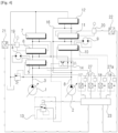
- Fig. 4 shows the hydraulic circuit of the electrical straight traveling apparatus for the construction machine according to the embodiment of the present invention.
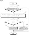
- Fig. 5 shows the flow chart for the control method of the electrical straight traveling apparatus for the construction machine according to the embodiment of the present invention.
- Fig. 6 shows the hydraulic circuit of the electrical straight traveling apparatus for the construction machine according to another embodiment of the present invention.
- Fig. 7 shows the flow chart for the control method of the electrical straight traveling apparatus for the construction machine according to another embodiment of the present invention.
- the straight traveling apparatus for the construction machine according to the embodiment of the present invention, the first and second variable displacement hydraulic pumps (hereinafter, the first and second hydraulic pumps) (1, 2) and the pilot pump (not drawn) are connected to the engine.
- the first and second hydraulic pumps hereinafter, the first and second hydraulic pumps (1, 2) and the pilot pump (not drawn) are connected to the engine.
- a first travel control valves (5) and first working control valves (6, 7) are installed in a flow path (3) that is connected to the first hydraulic pump (1).
- the first control valve(5) controls the hydraulic oil that is supplied to the left travel motor(4) and the first working device control valves (6, 7) controls the hydraulic oil that is supplied to the first working device (e.g. arm).
- the straight travel valve (14) is installed in the upstream of the path (8), which is switched by the pilot pressure operated by the electrical control valve (13).
- the straight travel valve (14) is switched so that the hydraulic oil of the first hydraulic pump (1) is supplied to the left travel motor (4) and right travel motor (9), respectively, while the hydraulic oil of the second hydraulic pump (2) is supplied to the first working device and the second working device, respectively.
- the straight travel valve (14) may be installed in the upstream of the path (3) of the first hydraulic pump (1).
- the straight travel valve (14) is switched so that the hydraulic oil of the second hydraulic pump (2) is supplied to the left travel motor (4) and right travel motor (9), respectively, while the hydraulic oil of the first hydraulic pump (1) is supplied to the first working device and the second working device, respectively.
- the pressure sensors (17, 18) are installed in the path between the drive pedals (27, 27a) and the first and second travel motor control valves (5, 10), and detect the pilot pressures applied to the first and second travel motor control valves (5, 10) by the drive pedals (27, 27a).
- the pressure sensors (21, 22) are installed in the path between the joy sticks (19. 20) and the first and second working device switch valves (6, 7, 11, 12), and detect the pilot pressures applied to the first and second working device control valves (6, 7, 11, 12) by the joy sticks (19,20).
- the controller (23) that is connected to the pressure sensors (17, 18, 21, 22) and the electrical control valve (13), and outputs a control signal to the electrical control valve (13) so that the pilot pressure applied to the straight travel valve (14) is blocked in case that a difference (Pd) between the pilot pressures applied to the first and second travel motor control valves (5,10) is larger than the pre-set pressure value (Ps), when the first and second working devices are operated during the travel.
- the electrical control valve includes a proportional pressure reducing valve (PPRV), the proportional pressure reducing valve being adjusted to allow the pilot pressure from the pilot pump to the straight travel valve (14), in response to an electrical signal that is applied from the controller (23).
- PPRV proportional pressure reducing valve
- the machine can drive straight since a single travel is prevented even under the load of the working device.
- the left and right travel motors (4, 9) are operated by the hydraulic oil supplied from the first and second variable displacement hydraulic pumps (1, 2) in response to an amount of the pilot pressure that is generated by a manipulation of the drive pedals (27, 27a), thereby enabling the machine to make the curved travel at the driver's intention.
- the second control valve (10) for controlling the hydraulic oil that is supplied to the right travel motor (9) and the second working device control valve (11, 12) for controlling the hydraulic oil that is supplied to the second working device (e.g. boom).
- the straight travel valve (14) may be installed in the upstream of the flow path (3) of the first hydraulic pump (1).
- the straight travel valve (14) is switched so that the hydraulic oil of the second hydraulic pump (2) is supplied to the left travel motor (4) and right travel motor (9), respectively, while the hydraulic oil discharged from the first hydraulic pump (1) is supplied to the first working device and the second working device, respectively.
- a first shuttle valve (24) is provided in flow paths between the left travel motor control valves (5) and the straight travel detection valve (26), wherein a first shuttle valve selects the pilot pressure which is relatively higher between the pilot pressures applied at both ends of the left travel motor control valve (5), and applies the selected pilot pressure to one pressure port of the straight travel detection valve (26).
- the calculated pressure difference (Pd) is compared with the pre-set pressure value (Ps) of the valve spring at both ends of the straight travel detection valve (26). If the calculated pressure difference (Pd) is smaller than the pre-set pressure value (Ps) of the valve spring, it proceeds to "S300A" as a straight travel mode is recognized.
- the straight travel function is blocked and the curved travel can be maintained.
Landscapes
- Engineering & Computer Science (AREA)
- General Engineering & Computer Science (AREA)
- Mining & Mineral Resources (AREA)
- Civil Engineering (AREA)
- Structural Engineering (AREA)
- Physics & Mathematics (AREA)
- Fluid Mechanics (AREA)
- Mechanical Engineering (AREA)
- Operation Control Of Excavators (AREA)
- Fluid-Pressure Circuits (AREA)
Claims (7)
- Baumaschine umfassend;eine erste und eine zweite Hydraulikpumpe mit variabler Fördermenge (1, 2) und eine Pilotpumpe (17);einen linken Fahrmotor (4) und eine erste Arbeitsvorrichtung, die von der ersten Hydraulikpumpe mit variabler Fördermenge (1) betrieben werden;mehrere Steuerventile (5, 6, 7), die in einem Strömungsweg (3) der ersten Hydraulikpumpe mit variabler Fördermenge (1) installiert sind und das dem linken Fahrmotor (4) oder der ersten Arbeitsvorrichtung zugeführte Hydrauliköl steuern;einen rechten Fahrmotor (9) und eine zweite Arbeitsvorrichtung, die von der zweiten Hydraulikpumpe mit variabler Fördermenge (2) betrieben werden;mehrere Steuerventile (10, 11, 12), die in einem Strömungsweg (8) der zweiten Hydraulikpumpe mit variabler Fördermenge (2) installiert sind und das dem rechten Fahrmotor (9) oder der zweiten Arbeitsvorrichtung zugeführte Hydrauliköl steuern;ein Geradeausfahrtventil (14), das durch einen von einem elektrischen Steuerventil (13) induzierten Pilotdruck umgeschaltet wird, wobei das Geradeausfahrtventil (14), wenn es umgeschaltet ist, das Hydrauliköl einer der ersten und zweiten Hydraulikpumpen mit variabler Fördermenge (1, 2) dem linken und rechten Fahrmotor (4, 9) zuführt, während es das Hydrauliköl der anderen der ersten und zweiten Hydraulikpumpen mit variabler Fördermenge (1, 2) der ersten und zweiten Arbeitsvorrichtung zuführt; und einen Druckerfassungssensor (17, 18, 21, 22) zum Erfassen eines Pilotdrucks, der auf das linke und das rechte Fahrmotorsteuerventil (5, 10) und den Pilotdruck, der auf das erste und das zweite Arbeitsvorrichtung-Steuerventil (6, 7, 11, 12) wirkt, aufgebracht wird;dadurch gekennzeichnet, dass die Baumaschine ferner umfasst:
eine Steuerung (23), die ein Steuersignal an das elektrische Steuerventil (13) ausgibt, so dass der an das Geradeausfahrtventil (14) aufgebrachte Pilotdruck blockiert wird, wenn eine Druckdifferenz zwischen den an das linke und das rechte Fahrmotorsteuerventil (5, 10) aufgebrachten Pilotdrücken größer als ein voreingestellter Druckwert ist, wenn die erste und die zweite Arbeitsvorrichtung während einer Fahrt betätigt werden. - Baumaschine nach Anspruch 1, wobei das elektrische Steuerventil (13) ein Magnetventil aufweist, bei dem das Magnetventil durch ein von der Steuerung (23) angelegtes Steuersignal zwischen einer Ausgangszustandsposition und einer Ein-Zustandsposition eingestellt wird, wobei das Magnetventil umgeschaltet wird, um in der Ausgangszustandsposition den von der Pilotpumpe (17) an das Geradeausfahrtventil (14) angelegten Pilotdruck zu blockieren und in der Ein-Zustandsposition den Pilotdruck von der Pilotpumpe (17) an das Geradeausfahrtventil (14) zu liefern.
- Baumaschine nach Anspruch 1, wobei das elektrische Steuerventil (13) ein Proportional-Druckreduzierventil aufweist, wobei das Proportional-Druckreduzierventil eingestellt ist, um den Pilotdruck von der Pilotpumpe (17) zum Geradeausfahrtventil (14) in Reaktion auf ein elektrisches Signal, das von der Steuerung (23) angelegt wird, zuzulassen.
- Baumaschine umfassend;eine erste und eine zweite Hydraulikpumpe (1, 2) mit variabler Fördermenge und eine Pilotpumpe (17);einen linken Fahrmotor (4) und eine erste Arbeitsvorrichtung, die von der ersten Hydraulikpumpe mit variabler Fördermenge (1) betrieben werden;mehrere Steuerventile (5, 6, 7), die in einem Strömungsweg (3) der ersten Hydraulikpumpe mit variabler Fördermenge (1) installiert sind und das dem linken Fahrmotor (4) oder der ersten Arbeitsvorrichtung zugeführte Hydrauliköl steuern;einen rechten Fahrmotor (9) und eine zweite Arbeitsvorrichtung, die von der zweiten Hydraulikpumpe mit variabler Fördermenge (2) betrieben werden;mehrere Steuerventile (10, 11, 12), die in einem Strömungsweg (8) der zweiten Hydraulikpumpe mit variabler Fördermenge (2) installiert sind und das dem rechten Fahrmotor (9) oder der zweiten Arbeitsvorrichtung zugeführte Hydrauliköl steuern;ein Geradeausfahrtventil (14), das durch einen von der Pilotpumpe (17) aufgebrachten Pilotdruck umgeschaltet wird und das Hydrauliköl einer der ersten und zweiten Hydraulikpumpen mit variabler Fördermenge (1, 2) dem linken und rechten Fahrmotor (4, 9) zuführt, während es das Hydrauliköl der anderen der ersten und zweiten Hydraulikpumpen mit variabler Fördermenge (1, 2) der ersten und zweiten Arbeitsvorrichtung zuführt; und ein Geradeausfahrt-Erkennungsventil (26), das in einem Strömungsweg zwischen der Pilotpumpe (17) und dem Geradeausfahrtventil (14) installiert ist,dadurch gekennzeichnet, dass das Geradeausfahrt-Erkennungsventil (26) umgeschaltet wird und den an das Geradeausfahrtventil (14) angelegten Pilotdruck blockiert, wenn eine Druckdifferenz zwischen jedem der an das linke und rechte Fahrmotorsteuerventil (5, 10) aufgebrachten Pilotdrücke größer ist als der voreingestellte Druckwert einer Ventilfeder an beiden Enden des Geradeausfahrt-Erkennungsventils (26), wenn die erste und zweite Arbeitsvorrichtung während einer Fahrt betätigt werden.
- Baumaschine nach Anspruch 4,
ferner umfassend:ein erstes Wechselventil (24) zur Auswahl des Pilotdrucks, der relativ höher ist zwischen den Pilotdrücken an beiden Enden des linken Fahrmotorsteuerventils (5), und zum Aufbringen des ausgewählten Pilotdrucks an einen Druckaufnahmeanschluss des Geradeausfahrt-Erkennungsventils (26); undein zweites Wechselventil (25) zum Auswählen des Pilotdrucks, der relativ höher ist zwischen den Pilotdrücken an beiden Enden des linken Fahrmotorsteuerventils (10), und zum Aufbringen des ausgewählten Pilotdrucks an den anderen Druckaufnahmeanschluss des Geradeausfahrt-Erkennungsventils (26). - Verfahren zur Steuerung einer Baumaschine mit einem linken Fahrmotor (4) und einer ersten Arbeitsvorrichtung, die von der ersten Hydraulikpumpe (1) betrieben werden; einem linken Fahrmotorsteuerventil (5) und einem ersten Arbeitsvorrichtung-Steuerventil (6, 7), die in einem Strömungsweg (3) installiert sind, der mit der ersten Hydraulikpumpe (1) verbunden ist; einem rechten Fahrmotor (9) und einer zweiten Arbeitsvorrichtung, die von der zweiten Hydraulikpumpe (2) betrieben werden; einem Steuerventil (10) für den rechten Fahrmotor und einem Steuerventil (11, 12) für die zweite Arbeitsvorrichtung, die in einem Strömungsweg (8) installiert sind, der mit der zweiten Hydraulikpumpe (2) verbunden ist; einem Geradeausfahrtventil (14), das durch einen Pilotdruck umgeschaltet wird, der von einem elektrischen Steuerventil (13) aufgebracht wird; einem Druckerfassungssensor (17, 18, 21, 22) zum Erfassen der Pilotdrücke, die an das linke und das rechte Fahrmotorsteuerventil (5, 10) sowie an das erste und das zweite Arbeitsvorrichtung-Steuerventil (6, 7, 11, 12) aufgebracht werden; und einer Steuerung (23), in die ein Erfassungssignal von dem Druckerfassungssensor (17, 18, 21, 22) eingegeben wird, das Verfahren umfassend:einen Schritt (S10) des Erfassens der Pilotdrücke, die auf das linke und das rechte Fahrmotorsteuerventil (5, 10) und dem Pilotdruck, der auf das erste und das zweite Arbeitsvorrichtung-Steuerventil (6, 7, 11, 12) aufgebracht werden;dadurch gekennzeichnet, dass das Verfahren ferner umfasst:einen Schritt (S20) zur Berechnung einer Druckdifferenz zwischen jedem der Pilotdrücke, die auf das linke und das rechte Fahrmotorsteuerventil (5, 10) aufgebracht werden;einen Schritt (S30) zum Vergleichen der berechneten Druckdifferenz mit dem voreingestellten Druckwert, wenn die erste und die zweite Arbeitsvorrichtung während einer Fahrt betätigt werden; undeinen Schritt (S40A) des Erkennens eines Kurvenfahrmodus, wenn die berechnete Differenz größer als der voreingestellte Druckwert ist, und des Blockierens des Pilotdrucks, der vom elektrischen Steuerventil (13) auf das Geradeausfahrtventil (14) aufgebracht wird.
- Verfahren zur Steuerung einer Baumaschine nach Anspruch 6, ferner umfassend einen Schritt (S40), bei dem ein Geradeausfahrtmodus erkannt wird, wenn die berechnete Differenz unter dem voreingestellten Druckwert liegt, und das Geradeausfahrtventil (14) durch den vom elektrischen Steuerventil (13) aufgebrachten Pilotdruck umgeschaltet wird.
Applications Claiming Priority (1)
| Application Number | Priority Date | Filing Date | Title |
|---|---|---|---|
| PCT/KR2014/010553 WO2016072535A1 (ko) | 2014-11-05 | 2014-11-05 | 건설기계용 주행직진장치 및 그 제어방법 |
Publications (4)
| Publication Number | Publication Date |
|---|---|
| EP3216927A1 EP3216927A1 (de) | 2017-09-13 |
| EP3216927A4 EP3216927A4 (de) | 2018-08-01 |
| EP3216927C0 EP3216927C0 (de) | 2025-01-01 |
| EP3216927B1 true EP3216927B1 (de) | 2025-01-01 |
Family
ID=55909257
Family Applications (1)
| Application Number | Title | Priority Date | Filing Date |
|---|---|---|---|
| EP14905308.4A Active EP3216927B1 (de) | 2014-11-05 | 2014-11-05 | Vorrichtung für geradeausfahrt für eine baumaschine und steuerungsverfahren dafür |
Country Status (4)
| Country | Link |
|---|---|
| US (1) | US10337170B2 (de) |
| EP (1) | EP3216927B1 (de) |
| CN (1) | CN107075832B (de) |
| WO (1) | WO2016072535A1 (de) |
Families Citing this family (10)
| Publication number | Priority date | Publication date | Assignee | Title |
|---|---|---|---|---|
| KR102540110B1 (ko) * | 2017-01-10 | 2023-06-05 | 에이치디현대인프라코어 주식회사 | 건설 기계의 유압 시스템 |
| KR102133312B1 (ko) * | 2017-09-08 | 2020-07-13 | 히다찌 겐끼 가부시키가이샤 | 유압 구동 장치 |
| CN108729491A (zh) * | 2018-05-24 | 2018-11-02 | 柳州柳工挖掘机有限公司 | 履带式挖掘机行走控制系统及控制方法 |
| CN108755826A (zh) * | 2018-05-24 | 2018-11-06 | 柳州柳工挖掘机有限公司 | 履带式挖掘机转向自动变速控制系统及控制方法 |
| CN108755829A (zh) * | 2018-05-24 | 2018-11-06 | 柳州柳工挖掘机有限公司 | 履带式挖掘机转向自动变速控制系统及控制方法 |
| CN109183893B (zh) * | 2018-09-26 | 2020-09-01 | 徐州工程学院 | 一种基于负载敏感的挖掘机回转节能液压系统及控制方法 |
| KR102564414B1 (ko) * | 2018-10-29 | 2023-08-08 | 에이치디현대인프라코어 주식회사 | 건설기계의 주행 제어 시스템 및 건설기계의 주행 제어 방법 |
| JP6703585B2 (ja) * | 2018-11-01 | 2020-06-03 | Kyb株式会社 | 流体圧制御装置 |
| JP7209607B2 (ja) * | 2019-09-26 | 2023-01-20 | 日立建機株式会社 | 作業機械 |
| US12085099B1 (en) * | 2020-06-18 | 2024-09-10 | Vacuworx Global, LLC | Flow control block for use with a vacuum material handler |
Citations (1)
| Publication number | Priority date | Publication date | Assignee | Title |
|---|---|---|---|---|
| US20030037465A1 (en) * | 2001-08-22 | 2003-02-27 | Kobelco Construction Machinery Co. Ltd., | Hydraulic system for construction machine |
Family Cites Families (20)
| Publication number | Priority date | Publication date | Assignee | Title |
|---|---|---|---|---|
| JPH07122276B2 (ja) * | 1989-07-07 | 1995-12-25 | 油谷重工株式会社 | 建設機械の油圧ポンプ制御回路 |
| JP2776702B2 (ja) * | 1992-09-18 | 1998-07-16 | 新キャタピラー三菱株式会社 | 建設機械の油圧回路 |
| JPH06306892A (ja) | 1993-04-23 | 1994-11-01 | Yutani Heavy Ind Ltd | 建設機械の走行制御装置 |
| JP4111286B2 (ja) * | 1998-06-30 | 2008-07-02 | コベルコ建機株式会社 | 建設機械の走行制御方法及び同装置 |
| US6148545A (en) | 1999-09-27 | 2000-11-21 | Yeager, Jr.; James L. | Boot warmer |
| JP2002021808A (ja) * | 2000-07-10 | 2002-01-23 | Shin Caterpillar Mitsubishi Ltd | 作業機械の液圧回路 |
| JP4212225B2 (ja) * | 2000-07-28 | 2009-01-21 | 株式会社小松製作所 | 建設機械における走行油圧回路 |
| WO2003089295A2 (en) | 2002-04-18 | 2003-10-30 | Airbus Deutschland Gmbh | Perforated skin structure for laminar-flow systems |
| JP2005201301A (ja) * | 2004-01-13 | 2005-07-28 | Hitachi Constr Mach Co Ltd | 可変容量型油圧ポンプの傾転制御装置 |
| KR101156859B1 (ko) * | 2004-12-29 | 2012-06-20 | 두산인프라코어 주식회사 | 굴삭기의 오작동 방지장치 |
| KR100753986B1 (ko) * | 2006-04-18 | 2007-08-31 | 볼보 컨스트럭션 이키프먼트 홀딩 스웨덴 에이비 | 주행직진용 유압회로 |
| KR100753990B1 (ko) * | 2006-08-29 | 2007-08-31 | 볼보 컨스트럭션 이키프먼트 홀딩 스웨덴 에이비 | 주행직진용 유압회로 |
| KR100900436B1 (ko) * | 2007-05-21 | 2009-06-01 | 볼보 컨스트럭션 이키프먼트 홀딩 스웨덴 에이비 | 무한궤도형 중장비의 주행장치 |
| KR101356008B1 (ko) * | 2007-06-01 | 2014-01-27 | 볼보 컨스트럭션 이큅먼트 에이비 | 크롤러식 굴삭기의 주행모터 과속 방지장치 |
| KR101213528B1 (ko) * | 2010-05-20 | 2012-12-18 | 가부시키가이샤 고마쓰 세이사쿠쇼 | 작업 차량 및 작업 차량의 제어 방법 |
| US8480713B2 (en) * | 2010-07-28 | 2013-07-09 | Warsaw Orthopedic, Inc. | Adjustable spinal connector assembly |
| WO2013089295A1 (ko) * | 2011-12-15 | 2013-06-20 | 볼보 컨스트럭션 이큅먼트 에이비 | 건설기계의 주행 제어시스템 |
| CN102605812B (zh) * | 2012-03-22 | 2014-06-25 | 三一重机有限公司 | 一种挖掘机直线行走控制装置及控制方法 |
| CN102888873B (zh) * | 2012-09-12 | 2015-03-11 | 徐州徐工挖掘机械有限公司 | 一种提高挖掘机复合动作时直线行走性能的装置 |
| WO2014148449A1 (ja) * | 2013-03-22 | 2014-09-25 | 日立建機株式会社 | 建設機械の油圧駆動装置 |
-
2014
- 2014-11-05 EP EP14905308.4A patent/EP3216927B1/de active Active
- 2014-11-05 CN CN201480083191.0A patent/CN107075832B/zh active Active
- 2014-11-05 US US15/519,842 patent/US10337170B2/en active Active
- 2014-11-05 WO PCT/KR2014/010553 patent/WO2016072535A1/ko not_active Ceased
Patent Citations (1)
| Publication number | Priority date | Publication date | Assignee | Title |
|---|---|---|---|---|
| US20030037465A1 (en) * | 2001-08-22 | 2003-02-27 | Kobelco Construction Machinery Co. Ltd., | Hydraulic system for construction machine |
Also Published As
| Publication number | Publication date |
|---|---|
| EP3216927C0 (de) | 2025-01-01 |
| CN107075832A (zh) | 2017-08-18 |
| US10337170B2 (en) | 2019-07-02 |
| WO2016072535A1 (ko) | 2016-05-12 |
| EP3216927A4 (de) | 2018-08-01 |
| CN107075832B (zh) | 2020-05-26 |
| EP3216927A1 (de) | 2017-09-13 |
| US20170268201A1 (en) | 2017-09-21 |
Similar Documents
| Publication | Publication Date | Title |
|---|---|---|
| EP3216927B1 (de) | Vorrichtung für geradeausfahrt für eine baumaschine und steuerungsverfahren dafür | |
| EP2660479B1 (de) | Hydraulische pumpe für eine baumaschine | |
| EP1995155B1 (de) | Antriebsvorrichtung für Raupen-Baumaschinen | |
| JP6603568B2 (ja) | 油圧駆動システム | |
| CN103597218B (zh) | 用于工程机械的液压系统 | |
| KR101742322B1 (ko) | 전자유압펌프용 비상 제어부를 포함하는 건설기계의 유압 시스템 | |
| KR101953049B1 (ko) | 작업 기계의 압유 에너지 재생 장치 | |
| JP2017110672A5 (de) | ||
| CN103429828B (zh) | 用于施工机械的驱动控制系统 | |
| US10577777B2 (en) | Control system for construction machinery | |
| KR20110100285A (ko) | 건설 기계의 유압펌프 유량 제어장치 | |
| CN103052755B (zh) | 用于控制施工设备的装置 | |
| KR20140037007A (ko) | 건설장비용 유압시스템 | |
| CN104520596A (zh) | 用于施工机械的液压系统 | |
| KR102543030B1 (ko) | 작업 기계 | |
| EP3133211B1 (de) | Antriebssteuerungsvorrichtung für eine baumaschine | |
| JPH0941427A (ja) | 油圧作業機 | |
| EP3222784A1 (de) | Verfahren zur steuerung eines hydraulikhydraulikkreises für eine baumaschine | |
| JP5351833B2 (ja) | 建設機械の油圧回路 | |
| KR102475528B1 (ko) | 건설기계의 제어장치 및 제어방법 | |
| KR20150114954A (ko) | 유압식 건설기계 | |
| JPH10311065A (ja) | 油圧式建設作業機械の制御装置 | |
| KR20080048712A (ko) | 주행 직진장치 | |
| KR20180025635A (ko) | 굴삭기의 유압 제어장치 |
Legal Events
| Date | Code | Title | Description |
|---|---|---|---|
| STAA | Information on the status of an ep patent application or granted ep patent |
Free format text: STATUS: THE INTERNATIONAL PUBLICATION HAS BEEN MADE |
|
| PUAI | Public reference made under article 153(3) epc to a published international application that has entered the european phase |
Free format text: ORIGINAL CODE: 0009012 |
|
| STAA | Information on the status of an ep patent application or granted ep patent |
Free format text: STATUS: REQUEST FOR EXAMINATION WAS MADE |
|
| 17P | Request for examination filed |
Effective date: 20170602 |
|
| AK | Designated contracting states |
Kind code of ref document: A1 Designated state(s): AL AT BE BG CH CY CZ DE DK EE ES FI FR GB GR HR HU IE IS IT LI LT LU LV MC MK MT NL NO PL PT RO RS SE SI SK SM TR |
|
| AX | Request for extension of the european patent |
Extension state: BA ME |
|
| RIN1 | Information on inventor provided before grant (corrected) |
Inventor name: KIM, SUNG-GON Inventor name: JOUNG, HEA-GYOON |
|
| DAX | Request for extension of the european patent (deleted) | ||
| A4 | Supplementary search report drawn up and despatched |
Effective date: 20180628 |
|
| RIC1 | Information provided on ipc code assigned before grant |
Ipc: E02F 9/22 20060101ALI20180622BHEP Ipc: F15B 11/17 20060101ALI20180622BHEP Ipc: E02F 9/02 20060101AFI20180622BHEP |
|
| STAA | Information on the status of an ep patent application or granted ep patent |
Free format text: STATUS: EXAMINATION IS IN PROGRESS |
|
| 17Q | First examination report despatched |
Effective date: 20211102 |
|
| GRAP | Despatch of communication of intention to grant a patent |
Free format text: ORIGINAL CODE: EPIDOSNIGR1 |
|
| STAA | Information on the status of an ep patent application or granted ep patent |
Free format text: STATUS: GRANT OF PATENT IS INTENDED |
|
| INTG | Intention to grant announced |
Effective date: 20240612 |
|
| GRAS | Grant fee paid |
Free format text: ORIGINAL CODE: EPIDOSNIGR3 |
|
| GRAA | (expected) grant |
Free format text: ORIGINAL CODE: 0009210 |
|
| STAA | Information on the status of an ep patent application or granted ep patent |
Free format text: STATUS: THE PATENT HAS BEEN GRANTED |
|
| AK | Designated contracting states |
Kind code of ref document: B1 Designated state(s): AL AT BE BG CH CY CZ DE DK EE ES FI FR GB GR HR HU IE IS IT LI LT LU LV MC MK MT NL NO PL PT RO RS SE SI SK SM TR |
|
| REG | Reference to a national code |
Ref country code: GB Ref legal event code: FG4D |
|
| REG | Reference to a national code |
Ref country code: CH Ref legal event code: EP |
|
| REG | Reference to a national code |
Ref country code: DE Ref legal event code: R096 Ref document number: 602014091414 Country of ref document: DE |
|
| REG | Reference to a national code |
Ref country code: IE Ref legal event code: FG4D |
|
| U01 | Request for unitary effect filed |
Effective date: 20250129 |
|
| U07 | Unitary effect registered |
Designated state(s): AT BE BG DE DK EE FI FR IT LT LU LV MT NL PT RO SE SI Effective date: 20250204 |
|
| PG25 | Lapsed in a contracting state [announced via postgrant information from national office to epo] |
Ref country code: PL Free format text: LAPSE BECAUSE OF FAILURE TO SUBMIT A TRANSLATION OF THE DESCRIPTION OR TO PAY THE FEE WITHIN THE PRESCRIBED TIME-LIMIT Effective date: 20250101 |
|
| PG25 | Lapsed in a contracting state [announced via postgrant information from national office to epo] |
Ref country code: ES Free format text: LAPSE BECAUSE OF FAILURE TO SUBMIT A TRANSLATION OF THE DESCRIPTION OR TO PAY THE FEE WITHIN THE PRESCRIBED TIME-LIMIT Effective date: 20250101 |
|
| PG25 | Lapsed in a contracting state [announced via postgrant information from national office to epo] |
Ref country code: IS Free format text: LAPSE BECAUSE OF FAILURE TO SUBMIT A TRANSLATION OF THE DESCRIPTION OR TO PAY THE FEE WITHIN THE PRESCRIBED TIME-LIMIT Effective date: 20250501 Ref country code: NO Free format text: LAPSE BECAUSE OF FAILURE TO SUBMIT A TRANSLATION OF THE DESCRIPTION OR TO PAY THE FEE WITHIN THE PRESCRIBED TIME-LIMIT Effective date: 20250401 |
|
| PG25 | Lapsed in a contracting state [announced via postgrant information from national office to epo] |
Ref country code: HR Free format text: LAPSE BECAUSE OF FAILURE TO SUBMIT A TRANSLATION OF THE DESCRIPTION OR TO PAY THE FEE WITHIN THE PRESCRIBED TIME-LIMIT Effective date: 20250101 |
|
| PG25 | Lapsed in a contracting state [announced via postgrant information from national office to epo] |
Ref country code: GR Free format text: LAPSE BECAUSE OF FAILURE TO SUBMIT A TRANSLATION OF THE DESCRIPTION OR TO PAY THE FEE WITHIN THE PRESCRIBED TIME-LIMIT Effective date: 20250402 |
|
| PG25 | Lapsed in a contracting state [announced via postgrant information from national office to epo] |
Ref country code: CZ Free format text: LAPSE BECAUSE OF FAILURE TO SUBMIT A TRANSLATION OF THE DESCRIPTION OR TO PAY THE FEE WITHIN THE PRESCRIBED TIME-LIMIT Effective date: 20250101 |
|
| PG25 | Lapsed in a contracting state [announced via postgrant information from national office to epo] |
Ref country code: SM Free format text: LAPSE BECAUSE OF FAILURE TO SUBMIT A TRANSLATION OF THE DESCRIPTION OR TO PAY THE FEE WITHIN THE PRESCRIBED TIME-LIMIT Effective date: 20250101 |
|
| PG25 | Lapsed in a contracting state [announced via postgrant information from national office to epo] |
Ref country code: SK Free format text: LAPSE BECAUSE OF FAILURE TO SUBMIT A TRANSLATION OF THE DESCRIPTION OR TO PAY THE FEE WITHIN THE PRESCRIBED TIME-LIMIT Effective date: 20250101 |
|
| PLBE | No opposition filed within time limit |
Free format text: ORIGINAL CODE: 0009261 |
|
| STAA | Information on the status of an ep patent application or granted ep patent |
Free format text: STATUS: NO OPPOSITION FILED WITHIN TIME LIMIT |
|
| 26N | No opposition filed |
Effective date: 20251002 |
|
| U20 | Renewal fee for the european patent with unitary effect paid |
Year of fee payment: 12 Effective date: 20251126 |