EP3217195A1 - Capteur optique - Google Patents
Capteur optique Download PDFInfo
- Publication number
- EP3217195A1 EP3217195A1 EP16159085.6A EP16159085A EP3217195A1 EP 3217195 A1 EP3217195 A1 EP 3217195A1 EP 16159085 A EP16159085 A EP 16159085A EP 3217195 A1 EP3217195 A1 EP 3217195A1
- Authority
- EP
- European Patent Office
- Prior art keywords
- optical sensor
- protective field
- sensor according
- protective
- switching
- Prior art date
- Legal status (The legal status is an assumption and is not a legal conclusion. Google has not performed a legal analysis and makes no representation as to the accuracy of the status listed.)
- Granted
Links
Images

Classifications
-
- G—PHYSICS
- G01—MEASURING; TESTING
- G01V—GEOPHYSICS; GRAVITATIONAL MEASUREMENTS; DETECTING MASSES OR OBJECTS; TAGS
- G01V8/00—Prospecting or detecting by optical means
- G01V8/10—Detecting, e.g. by using light barriers
-
- F—MECHANICAL ENGINEERING; LIGHTING; HEATING; WEAPONS; BLASTING
- F16—ENGINEERING ELEMENTS AND UNITS; GENERAL MEASURES FOR PRODUCING AND MAINTAINING EFFECTIVE FUNCTIONING OF MACHINES OR INSTALLATIONS; THERMAL INSULATION IN GENERAL
- F16P—SAFETY DEVICES IN GENERAL; SAFETY DEVICES FOR PRESSES
- F16P3/00—Safety devices acting in conjunction with the control or operation of a machine; Control arrangements requiring the simultaneous use of two or more parts of the body
- F16P3/12—Safety devices acting in conjunction with the control or operation of a machine; Control arrangements requiring the simultaneous use of two or more parts of the body with means, e.g. feelers, which in case of the presence of a body part of a person in or near the danger zone influence the control or operation of the machine
- F16P3/14—Safety devices acting in conjunction with the control or operation of a machine; Control arrangements requiring the simultaneous use of two or more parts of the body with means, e.g. feelers, which in case of the presence of a body part of a person in or near the danger zone influence the control or operation of the machine the means being photocells or other devices sensitive without mechanical contact
- F16P3/144—Safety devices acting in conjunction with the control or operation of a machine; Control arrangements requiring the simultaneous use of two or more parts of the body with means, e.g. feelers, which in case of the presence of a body part of a person in or near the danger zone influence the control or operation of the machine the means being photocells or other devices sensitive without mechanical contact using light grids
-
- G—PHYSICS
- G01—MEASURING; TESTING
- G01S—RADIO DIRECTION-FINDING; RADIO NAVIGATION; DETERMINING DISTANCE OR VELOCITY BY USE OF RADIO WAVES; LOCATING OR PRESENCE-DETECTING BY USE OF THE REFLECTION OR RERADIATION OF RADIO WAVES; ANALOGOUS ARRANGEMENTS USING OTHER WAVES
- G01S17/00—Systems using the reflection or reradiation of electromagnetic waves other than radio waves, e.g. lidar systems
- G01S17/02—Systems using the reflection of electromagnetic waves other than radio waves
- G01S17/04—Systems determining the presence of a target
-
- G—PHYSICS
- G01—MEASURING; TESTING
- G01S—RADIO DIRECTION-FINDING; RADIO NAVIGATION; DETERMINING DISTANCE OR VELOCITY BY USE OF RADIO WAVES; LOCATING OR PRESENCE-DETECTING BY USE OF THE REFLECTION OR RERADIATION OF RADIO WAVES; ANALOGOUS ARRANGEMENTS USING OTHER WAVES
- G01S17/00—Systems using the reflection or reradiation of electromagnetic waves other than radio waves, e.g. lidar systems
- G01S17/02—Systems using the reflection of electromagnetic waves other than radio waves
- G01S17/06—Systems determining position data of a target
- G01S17/42—Simultaneous measurement of distance and other co-ordinates
Definitions
- the invention relates to an optical sensor according to the preamble of claim 1.
- optical sensors are often used for hazardous area protection on machines and equipment.
- An example of such optical sensors are scanning distance sensors, that is, area distance sensors, by means of which the apron of a machine, a vehicle or a plant is monitored.
- These area distance sensors have a distance sensor element which emits transmitted light beams for the detection of objects.
- the area distance sensor has a deflection unit, by means of which the transmitted light beams are deflected periodically within a surface. With the area distance sensor, objects can then be located within the detected area, i. there is a position determination of the objects.
- a protective field of a predetermined size is defined in the area distance sensor, which forms a section of the area swept by transmitted light beams. Then, the area distance sensor detects whether an object penetrates into the protective field. As soon as this is the case, an object detection signal is generated in the area distance sensor, which preferably leads to the decommissioning of the monitored unit, so that in particular a hazard is excluded by a person penetrating into the protective field.
- a surface-distance sensor is known in which a plurality of protective fields with different dimensions are stored in an evaluation unit.
- a plurality of switches are connected via a respective supply line to an input of the evaluation unit, wherein each input is assigned a stored protective field. It is also known in the art that a protective field is associated with a combination of inputs, i. Different combinations of inputs can be assigned different protective fields.
- the invention has for its object to extend the functionality of an optical sensor of the type mentioned.
- the invention relates to an optical sensor for detecting objects in a detection area, comprising at least one transmitting light beam emissive transmitter, at least one receiving light beam receiving receiver and an evaluation unit for the evaluation of receiver signals generated in the receiver.
- an object detection signal is generated when an object is detected within an activated protective field.
- switching means are provided by means of which a protective field of a number of protective fields with different protective field configurations can be activated, wherein different protective field configurations are defined by different properties of objects to be detected and / or of different control variables.
- the basic idea of the invention is to provide switching means in the optical sensor in such a way that with these protective fields with different Protective field configurations can be selected and activated. It is essential that the individual protective fields have different functionalities with the protective field configurations. Thus, the activation of the various protective fields, the function of the optical sensor is changed, whereby a flexible adaptation of the optical sensor to different applications is possible.
- the different protective field configurations comprise properties of objects to be detected, that is, by activating protective fields with specific protective field configurations, the detection behavior of the optical sensor can be predetermined.
- the different protective field configurations can furthermore comprise different control variables, that is, by selecting protective fields with different protective field configurations, both the internal operating control of the optical sensor and controls of external units can be specified.
- the protective fields can of course also differ in their dimensions.
- the invention also covers the case that several protective fields can be activated at the same time.
- protective field configurations are defined by detectable object sizes of objects within the protective field.
- protective field configurations are defined by specific object types of objects within the protective field.
- reflectors are specified as specific object types.
- a detection of a specific object with specific properties which are formed in the case of a reflector of retroreflective properties, can thus be predetermined.
- the protective field configurations may be refined such that protective field configurations in the form of specific object classifications, such as, for example, different reflector sizes, are specified for the protective fields.
- a muting can be realized, that is, a specification of permissible objects within a protective field, in the detection of which an object detection signal is suppressed.
- protective field configurations are defined by specific start-up behavior of the optical sensor or a system monitored by the optical sensor.
- the startup behavior refers to the time after switching on the optical sensor and / or a system monitored by the optical sensor or to the time after an object intervention in the activated protective field.
- the startup behavior is defined by a self-test of the optical sensor.
- the startup behavior is defined by the dead time of a plant.
- the dead time may be due to the plant itself.
- the dead time can be stored in the system.
- the dead time in a system configuration can be predetermined by a safety test.
- the dead time may be due to any manual intervention required to unlock the system.
- parameters for external units are specified via the protective field configurations.
- the optical sensor is a safety sensor which has a fail-safe output controlled by the evaluation unit, via which a binary switching signal for controlling a system monitored by the optical sensor is output as the object detection signal.
- a switch-off command for the system is output via the fail-safe output as a switching signal.
- a secure serial transmission or another secure bus system can also be used.
- a changeover of a protective field performed with the switching means leaves the switching signal present at the fail-safe output unchanged.
- This type of protective field switching leads to a particularly high availability of the optical sensor, since the operation of the protective field switching, the relevant for the object monitoring switching signal remains valid, that is, there is no time gap in the monitoring with the optical sensor.
- the optical sensor particularly expediently has a memory unit in which a number of protective fields with different protective field configurations are stored. To activate a protective field, one of the stored protective fields is selected by means of the switching means.
- the memory unit can be integrated in the evaluation unit.
- the number of stored protective fields in this case specifies the switching options that are carried out with the switching means.
- the number of stored protective fields and protective field configurations can be suitably specified by a parameterization process and changed if necessary.
- the switching means have at least one input via which a switching command is generated by an external unit. This also includes the possibility of assigning different protective fields to different input combinations.
- the external unit may be formed by a control unit.
- the control unit may be formed by the vehicle control, which depends on the current driving state assign suitable protective field configurations by assigning switching commands.
- a switching command is generated in the switching means as a function of sensor signals generated with the optical sensor.
- the optical sensor itself generates switching commands. If the optical sensor is arranged, for example, on a vehicle such as a driverless transport system, then the speed and / or direction of travel of the vehicle can be determined on the basis of sensor signals generated by the optical sensor, wherein an automatic protective field switching can take place as a function of these parameters by means of the switching means.
- the switching means have an operator unit for user-guided protective field switching.
- the operating unit can be formed by a control panel such as a touch panel.
- a user can generate self-switching commands for protective field switching.
- the optical sensor may be a scanning distance sensor according to a first variant.
- the optical sensor can form a surface distance sensor, in which the transmitter and the receiver form a distance sensor and are arranged stationarily in a housing of the optical sensor.
- the distance sensor is associated with a deflection unit, for example in the form of a rotating mirror, via which the transmitted light beams are guided and thus guided periodically within a two-dimensional detection area.
- the scanning distance sensor may be configured so that the transmitter and receiver, which form the distance sensor, are arranged in a rotating measuring head.
- the optical sensor is a camera sensor.
- the receiver is formed by at least one image sensor, preferably a line-shaped or matrix-shaped CCD or CMOS array.
- a transmitter one or more light-emitting diodes or laser diodes are provided.
- Such a camera sensor can also be designed as a distance measuring system in that, for example, the distance to an object to be detected is determined for the individual photosensitive elements according to a transit time method.
- optical sensor is a working according to the light sensor principle light curtain.
- the optical sensor consists of a multiple array of light probes, each with a transmitter and a receiver.
- the transmitter and receiver can be housed in a common housing or in separate housings.
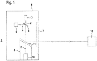
- FIG. 1 schematically shows the structure of an embodiment of the optical sensor according to the invention 1.
- the optical sensor 1 is formed in the present case as a surface distance sensor and comprises a transmitting light rays 2 emitting transmitter 3 in the form of a laser diode or the like and a receive light beams 4 receiving receiver 5 in the form of a photodiode or the like ,
- the transmitter 3 and the receiver 5 are arranged stationarily in a housing 6, in whose front wall an exit window 7 is arranged.
- a beam splitter 8 Through a beam splitter 8, a coaxial beam guidance of the transmitted light beams 2 and received light beams 4 is achieved.
- the transmitter 3 and the receiver 5 form a distance sensor, wherein the distance measurement takes place according to a pulse transit time or phase measuring method. Depending on the type of distance measurement, the transmitter 3 emits pulse-shaped or modulated with a modulation frequency transmitted light beams. 2
- the transmitted light beams 2 are deflected periodically via a deflection unit 9 in the form of a mirror 11 rotatable about a rotation axis by means of a motor 10.
- the transmitted light beams 2 are guided out of the housing 6 via the exit window 7. From an object 12, the transmitted light beams 2 are reflected back as receiving light beams 4 and passed through the exit window 7 and the beam splitter 8 to the receiver 5.
- the transmitted light beams 2 are guided in a flat detection area 13, in that object detection can be carried out by means of the optical sensor 1 ( FIG. 2 ).
- the optical sensor 1 FIG. 2
- a protective field 14 are activated.
- FIG. 3 shows a first embodiment of the electronic components of the optical sensor 1 according to FIG. 1 ,
- the optical sensor 1 in this case has an evaluation unit 15 in which received signals which are generated in the receiver 5 during object detection are evaluated. Depending on the received signals, an object detection signal is only generated when an object 12 is detected within the activated protective field 14. The object detection signal is output via an output 16.
- the optical sensor 1 is designed as a safety sensor and therefore has a fail-safe construction. This is achieved in particular by a redundant structure of the evaluation unit 15.
- the evaluation unit 15 consists of two mutually cyclically monitoring computer units.
- the output 16 is also formed fail-safe by a corresponding circuit structure. Via this output 16, a binary switching signal is output as an object detection signal, with which a system is controlled, on which a danger zone is monitored with the optical sensor 1. According to the danger zone, a protective field 14 is activated in the optical sensor 1. If, in the activated state, a particularly safety-critical object 12 is detected, a switch-off command for the system is output via the output 16 as a switching signal so that it can no longer pose a danger. If no such object 12 is detected in the protective field 14, a switching signal is output via the output 16, with which the operation of the system is enabled.
- the optical sensor 1 switching means by means of which a protective field switching can be performed.
- the switching means With the switching means Consequently, different protective fields 14 can be activated, within which the optical sensor 1 performs an object detection for generating the object detection signal, in particular of the switching signal.
- several different protective fields 14 are stored as parameterizable variables in the evaluation unit 15, it being possible to select and activate one of these protective fields 14 with the switching means, the object detection then taking place in the activated protective field 14.
- the individual protective fields 14 differ by specific protective field configurations.
- the protective field configurations can be defined by specific detectable object variables which are to be detected within the protective field 14.
- a minimum object size can be specified, so that only objects 12 whose size is greater than or equal to the minimum object size are detected during operation of the optical sensor 1 within this protective field 14.
- the protective field configuration of a protective field 14 can also be defined by specific objects 12 to be detected.
- a reflector can be specified as the object type for a protective field 14.
- object types are environmental or object contours that can be used for muting the optical sensor 1.
- protective field configurations can be defined by certain control variables. Examples include the startup behavior of the optical sensor 1 or the monitored system. In the first case, the startup behavior may be determined by the nature of the self-test of the optical sensor 1. In the second case, the startup behavior can be determined by the dead time of the system.
- the individual protective fields 14 can not only differ with regard to this protective field configuration. Rather, the protective fields 14 can also differ in terms of their dimensions.
- Essential elements of the switching means are implemented in the evaluation unit 15.
- a memory unit can be integrated in the evaluation unit 15, in which the different protective fields 14 are stored. Furthermore, with the evaluation unit 15, the activation of one of these protective fields 14 to then perform the object detection within this protective field 14.
- the switching command with which a protective field 14 is selected from the number of stored protective fields 14, can also be generated internally in the evaluation unit 15, preferably as a function of the sensor signals of the optical sensor 1.
- FIG. 3 shows a first example of this.
- an operating unit 17 is provided, such as a touch panel. Via this operating unit 17, a user can enter a switching command for selecting and activating a protective field.
- an input 18 is connected to the evaluation unit 15.
- a switching command is generated in an external unit and then read in via the input 18 into the evaluation unit 15.
- the protective field switching preferably leaves the switching signal of the optical sensor 1 unchanged, unless the switching state of the switching signal would change as a result of the change of the protective field 14.
Landscapes
- Physics & Mathematics (AREA)
- Engineering & Computer Science (AREA)
- Electromagnetism (AREA)
- General Physics & Mathematics (AREA)
- General Engineering & Computer Science (AREA)
- Computer Networks & Wireless Communication (AREA)
- Radar, Positioning & Navigation (AREA)
- Remote Sensing (AREA)
- Geophysics (AREA)
- General Life Sciences & Earth Sciences (AREA)
- Mechanical Engineering (AREA)
- Life Sciences & Earth Sciences (AREA)
- Optical Radar Systems And Details Thereof (AREA)
- Geophysics And Detection Of Objects (AREA)
Priority Applications (1)
| Application Number | Priority Date | Filing Date | Title |
|---|---|---|---|
| EP16159085.6A EP3217195B1 (fr) | 2016-03-08 | 2016-03-08 | Capteur optique |
Applications Claiming Priority (1)
| Application Number | Priority Date | Filing Date | Title |
|---|---|---|---|
| EP16159085.6A EP3217195B1 (fr) | 2016-03-08 | 2016-03-08 | Capteur optique |
Publications (2)
| Publication Number | Publication Date |
|---|---|
| EP3217195A1 true EP3217195A1 (fr) | 2017-09-13 |
| EP3217195B1 EP3217195B1 (fr) | 2023-04-26 |
Family
ID=55527804
Family Applications (1)
| Application Number | Title | Priority Date | Filing Date |
|---|---|---|---|
| EP16159085.6A Active EP3217195B1 (fr) | 2016-03-08 | 2016-03-08 | Capteur optique |
Country Status (1)
| Country | Link |
|---|---|
| EP (1) | EP3217195B1 (fr) |
Cited By (6)
| Publication number | Priority date | Publication date | Assignee | Title |
|---|---|---|---|---|
| CN109140579A (zh) * | 2018-07-25 | 2019-01-04 | 浙江工业大学 | 集测距、测温和加热一体的旋转式加热装置及方法 |
| EP3578319A1 (fr) * | 2018-06-07 | 2019-12-11 | Sick AG | Procédé de sécurisation d'un endroit dangereux |
| CN110895335A (zh) * | 2018-09-12 | 2020-03-20 | 西克股份公司 | 传感器和自主交通工具 |
| EP3770635A1 (fr) * | 2019-07-25 | 2021-01-27 | Leuze electronic GmbH + Co. KG | Capteur optique de sécurité à taux d'horloge variable et / ou activation intermédiaire de composants |
| EP3851729A1 (fr) * | 2020-01-16 | 2021-07-21 | Leuze electronic GmbH + Co. KG | Capteur optique et procédé de détection des objets au moyen d'un capteur optique |
| DE202023107245U1 (de) * | 2023-12-07 | 2025-03-12 | Leuze Electronic Gmbh & Co. Kg | Sensoranordnung |
Citations (7)
| Publication number | Priority date | Publication date | Assignee | Title |
|---|---|---|---|---|
| DE3912398A1 (de) * | 1989-04-15 | 1990-10-18 | Bayerische Motoren Werke Ag | Objekt-erkennungsvorrichtung fuer kraftfahrzeuge |
| DE19917509C1 (de) | 1999-04-17 | 2000-05-25 | Leuze Electronic Gmbh & Co | Optoelektronische Vorrichtung |
| EP1331433A2 (fr) * | 2002-01-25 | 2003-07-30 | Keyence Corporation | Dispositif de sécurité photoélectrique à chemin optique multiple |
| EP1443343A2 (fr) * | 2003-02-01 | 2004-08-04 | Leuze lumiflex GmbH + Co. KG | Détecteur optique avec plusiers sorties de commutation |
| DE102006012537A1 (de) * | 2006-03-18 | 2007-09-20 | Leuze Lumiflex Gmbh + Co. Kg | Lichtgitter |
| US20100097665A1 (en) * | 2008-10-22 | 2010-04-22 | Omron Scientific Technologies, Inc. | Apparatus and Method for Pattern-Based Configuration of Optical Sensing Systems |
| US20120123563A1 (en) * | 2010-11-17 | 2012-05-17 | Omron Scientific Technologies, Inc. | Method and Apparatus for Monitoring Zones |
-
2016
- 2016-03-08 EP EP16159085.6A patent/EP3217195B1/fr active Active
Patent Citations (7)
| Publication number | Priority date | Publication date | Assignee | Title |
|---|---|---|---|---|
| DE3912398A1 (de) * | 1989-04-15 | 1990-10-18 | Bayerische Motoren Werke Ag | Objekt-erkennungsvorrichtung fuer kraftfahrzeuge |
| DE19917509C1 (de) | 1999-04-17 | 2000-05-25 | Leuze Electronic Gmbh & Co | Optoelektronische Vorrichtung |
| EP1331433A2 (fr) * | 2002-01-25 | 2003-07-30 | Keyence Corporation | Dispositif de sécurité photoélectrique à chemin optique multiple |
| EP1443343A2 (fr) * | 2003-02-01 | 2004-08-04 | Leuze lumiflex GmbH + Co. KG | Détecteur optique avec plusiers sorties de commutation |
| DE102006012537A1 (de) * | 2006-03-18 | 2007-09-20 | Leuze Lumiflex Gmbh + Co. Kg | Lichtgitter |
| US20100097665A1 (en) * | 2008-10-22 | 2010-04-22 | Omron Scientific Technologies, Inc. | Apparatus and Method for Pattern-Based Configuration of Optical Sensing Systems |
| US20120123563A1 (en) * | 2010-11-17 | 2012-05-17 | Omron Scientific Technologies, Inc. | Method and Apparatus for Monitoring Zones |
Cited By (10)
| Publication number | Priority date | Publication date | Assignee | Title |
|---|---|---|---|---|
| EP3578319A1 (fr) * | 2018-06-07 | 2019-12-11 | Sick AG | Procédé de sécurisation d'un endroit dangereux |
| US10726538B2 (en) | 2018-06-07 | 2020-07-28 | Sick Ag | Method of securing a hazard zone |
| CN109140579A (zh) * | 2018-07-25 | 2019-01-04 | 浙江工业大学 | 集测距、测温和加热一体的旋转式加热装置及方法 |
| CN109140579B (zh) * | 2018-07-25 | 2021-05-04 | 浙江工业大学 | 集测距、测温和加热一体的旋转式加热装置及方法 |
| CN110895335A (zh) * | 2018-09-12 | 2020-03-20 | 西克股份公司 | 传感器和自主交通工具 |
| EP3623845B1 (fr) * | 2018-09-12 | 2022-06-22 | Sick Ag | Capteur et véhicule autonome |
| US11442167B2 (en) | 2018-09-12 | 2022-09-13 | Sick Ag | Sensor and autonomous vehicle |
| EP3770635A1 (fr) * | 2019-07-25 | 2021-01-27 | Leuze electronic GmbH + Co. KG | Capteur optique de sécurité à taux d'horloge variable et / ou activation intermédiaire de composants |
| EP3851729A1 (fr) * | 2020-01-16 | 2021-07-21 | Leuze electronic GmbH + Co. KG | Capteur optique et procédé de détection des objets au moyen d'un capteur optique |
| DE202023107245U1 (de) * | 2023-12-07 | 2025-03-12 | Leuze Electronic Gmbh & Co. Kg | Sensoranordnung |
Also Published As
| Publication number | Publication date |
|---|---|
| EP3217195B1 (fr) | 2023-04-26 |
Similar Documents
| Publication | Publication Date | Title |
|---|---|---|
| EP3217195A1 (fr) | Capteur optique | |
| DE19917509C1 (de) | Optoelektronische Vorrichtung | |
| EP2053538B1 (fr) | Protection d'une zone de surveillance et support visuel d'un usinage automatisé | |
| EP1816487B1 (fr) | Barrière optique | |
| DE10312972B3 (de) | Optischer Sensor | |
| DE102008032216A1 (de) | Vorrichtung zur Erkennung der Anwesenheit eines Objekts im Raum | |
| EP3220164B1 (fr) | Procédé de fonctionnement d'un capteur écartométrique de surveillance et capteur écartométrique de surveillance | |
| EP3587894A1 (fr) | Agencement de capteurs et procédé de fonctionnement d'un agencement de capteurs | |
| EP3401702A1 (fr) | Système de capteur | |
| DE202022103538U1 (de) | Überwachungsvorrichtung | |
| EP3882505B1 (fr) | Dispositif de surveillance et procédé de fonctionnement d'un dispositif de surveillance | |
| EP3640522B1 (fr) | Dispositif de surveillance | |
| EP3640521B1 (fr) | Dispositif de surveillance | |
| DE202015106835U1 (de) | Sensor | |
| EP3392679B1 (fr) | Capteur optique | |
| EP3919801B1 (fr) | Dispositif de surveillance | |
| EP3588130B1 (fr) | Capteur optique | |
| DE10155583B4 (de) | Schaltungsanordnung | |
| EP3862617B1 (fr) | Dispositif de sécurisation d'une zone dangereuse | |
| EP3809165B1 (fr) | Capteur | |
| EP3540380B1 (fr) | Dispositif de surveillance pour une installation | |
| DE102017103791B4 (de) | Optoelektronischer Sensor und Verfahren zur Erfassung von Objekten | |
| DE102017004030B4 (de) | Verfahren und Vorrichtung zum Sichern eines Arbeitsraums | |
| EP4119982B1 (fr) | Dispositif de surveillance et procédé de fonctionnement d'un dispositif de surveillance | |
| EP3663797A1 (fr) | Dispositif de surveillance |
Legal Events
| Date | Code | Title | Description |
|---|---|---|---|
| PUAI | Public reference made under article 153(3) epc to a published international application that has entered the european phase |
Free format text: ORIGINAL CODE: 0009012 |
|
| STAA | Information on the status of an ep patent application or granted ep patent |
Free format text: STATUS: REQUEST FOR EXAMINATION WAS MADE |
|
| 17P | Request for examination filed |
Effective date: 20170119 |
|
| AK | Designated contracting states |
Kind code of ref document: A1 Designated state(s): AL AT BE BG CH CY CZ DE DK EE ES FI FR GB GR HR HU IE IS IT LI LT LU LV MC MK MT NL NO PL PT RO RS SE SI SK SM TR |
|
| AX | Request for extension of the european patent |
Extension state: BA ME |
|
| STAA | Information on the status of an ep patent application or granted ep patent |
Free format text: STATUS: EXAMINATION IS IN PROGRESS |
|
| 17Q | First examination report despatched |
Effective date: 20210426 |
|
| GRAP | Despatch of communication of intention to grant a patent |
Free format text: ORIGINAL CODE: EPIDOSNIGR1 |
|
| STAA | Information on the status of an ep patent application or granted ep patent |
Free format text: STATUS: GRANT OF PATENT IS INTENDED |
|
| INTG | Intention to grant announced |
Effective date: 20230207 |
|
| GRAS | Grant fee paid |
Free format text: ORIGINAL CODE: EPIDOSNIGR3 |
|
| GRAA | (expected) grant |
Free format text: ORIGINAL CODE: 0009210 |
|
| STAA | Information on the status of an ep patent application or granted ep patent |
Free format text: STATUS: THE PATENT HAS BEEN GRANTED |
|
| RBV | Designated contracting states (corrected) |
Designated state(s): DE |
|
| AK | Designated contracting states |
Kind code of ref document: B1 Designated state(s): DE |
|
| REG | Reference to a national code |
Ref country code: DE Ref legal event code: R096 Ref document number: 502016015714 Country of ref document: DE |
|
| REG | Reference to a national code |
Ref country code: DE Ref legal event code: R097 Ref document number: 502016015714 Country of ref document: DE |
|
| PLBE | No opposition filed within time limit |
Free format text: ORIGINAL CODE: 0009261 |
|
| STAA | Information on the status of an ep patent application or granted ep patent |
Free format text: STATUS: NO OPPOSITION FILED WITHIN TIME LIMIT |
|
| 26N | No opposition filed |
Effective date: 20240129 |
|
| PGFP | Annual fee paid to national office [announced via postgrant information from national office to epo] |
Ref country code: DE Payment date: 20260319 Year of fee payment: 11 |
|
| P01 | Opt-out of the competence of the unified patent court (upc) registered |
Free format text: CASE NUMBER: UPC_APP_0010342_3217195/2026 Effective date: 20260319 |