EP3224400B1 - Séparateur centrifuge - Google Patents
Séparateur centrifuge Download PDFInfo
- Publication number
- EP3224400B1 EP3224400B1 EP15863811.4A EP15863811A EP3224400B1 EP 3224400 B1 EP3224400 B1 EP 3224400B1 EP 15863811 A EP15863811 A EP 15863811A EP 3224400 B1 EP3224400 B1 EP 3224400B1
- Authority
- EP
- European Patent Office
- Prior art keywords
- basket
- centrifugal separator
- controller
- speed
- spinning
- Prior art date
- Legal status (The legal status is an assumption and is not a legal conclusion. Google has not performed a legal analysis and makes no representation as to the accuracy of the status listed.)
- Active
Links
Images


Classifications
-
- F—MECHANICAL ENGINEERING; LIGHTING; HEATING; WEAPONS; BLASTING
- F26—DRYING
- F26B—DRYING SOLID MATERIALS OR OBJECTS BY REMOVING LIQUID THEREFROM
- F26B5/00—Drying solid materials or objects by processes not involving the application of heat
- F26B5/08—Drying solid materials or objects by processes not involving the application of heat by centrifugal treatment
-
- D—TEXTILES; PAPER
- D06—TREATMENT OF TEXTILES OR THE LIKE; LAUNDERING; FLEXIBLE MATERIALS NOT OTHERWISE PROVIDED FOR
- D06F—LAUNDERING, DRYING, IRONING, PRESSING OR FOLDING TEXTILE ARTICLES
- D06F49/00—Domestic spin-dryers or similar spin-dryers not suitable for industrial use
- D06F49/04—Bowl drive
-
- D—TEXTILES; PAPER
- D06—TREATMENT OF TEXTILES OR THE LIKE; LAUNDERING; FLEXIBLE MATERIALS NOT OTHERWISE PROVIDED FOR
- D06F—LAUNDERING, DRYING, IRONING, PRESSING OR FOLDING TEXTILE ARTICLES
- D06F37/00—Details specific to washing machines covered by groups D06F21/00 - D06F25/00
- D06F37/20—Mountings, e.g. resilient mountings, for the rotary receptacle, motor, tub or casing; Preventing or damping vibrations
- D06F37/24—Mountings, e.g. resilient mountings, for the rotary receptacle, motor, tub or casing; Preventing or damping vibrations in machines with a receptacle rotating or oscillating about a vertical axis
- D06F37/245—Damping vibrations by displacing, supplying or ejecting a material, e.g. liquid, into or from counterbalancing pockets
-
- D—TEXTILES; PAPER
- D06—TREATMENT OF TEXTILES OR THE LIKE; LAUNDERING; FLEXIBLE MATERIALS NOT OTHERWISE PROVIDED FOR
- D06F—LAUNDERING, DRYING, IRONING, PRESSING OR FOLDING TEXTILE ARTICLES
- D06F49/00—Domestic spin-dryers or similar spin-dryers not suitable for industrial use
- D06F49/06—Mountings, e.g. resilient mountings, for the bowl or casings; Preventing or damping vibrations
Definitions
- This invention relates to a centrifugal separator which uses centrifugal force to separate liquid from solids.
- the centrifugal separator is in the form of a spin dryer for separating water from clothing.
- US 4,328,600 discloses a conventional centrifugal separator according to the preamble of claim 1. However, the conventional centrifugal separator as disclosed in this publication still causes undesired vibrations and sound during operation.
- the embodiments of the invention disclose a centrifugal separator, such as a spin dryer for separating water from objects or wet clothing, such as bathing suits.
- a spin dryer is described herein, other uses for the centrifugal separator are encompassed by the invention including liquid separators in a laboratory setting or a manufacturing setting.
- Embodiments of the invention provide a centrifugal separator that includes a stationary chamber.
- the stationary chamber has a surrounding side wall or walls and a bottom floor.
- the housing includes a mechanical floor below the bottom floor.
- a basket is arranged to spin within the stationary chamber.
- the basket has a perforated surrounding sidewall.
- a motor is arranged below the bottom floor. The motor has a motor housing and an output shaft.
- the motor housing is fastened to the mechanical floor.
- a driveshaft is connected to the output shaft via a flexible coupling and the driveshaft passes through the bottom floor and is connected to the basket.
- the motor can comprise a DC or AC motor.
- a brake disc is operatively fixed to the output shaft, such as being fixed to the coupler, to rotate therewith, and a brake caliper is fixed to the mechanical floor.
- the caliper has brake shoes that are engagable to opposite faces of the brake disc.
- a balance ring having an annular chamber holding a balance fluid is mounted to an outside of the basket to rotate therewith.
- a control panel has a display that includes an indicator that circulates illuminated signals around a path to indicate the spinning of the basket.
- a fluid dispenser can be controlled by the controller to dispense a fluid, such as a liquid or gas, for example a fragrance, liquid solution or disinfectant, intermittently into the stationary chamber.
- a fluid such as a liquid or gas, for example a fragrance, liquid solution or disinfectant
- An ultraviolet light inside the stationary chamber can be controlled by the controller to intermittently illuminate to sterilize an inside of the chamber.
- Fins or blades can be arranged on the bottom of the basket to circulate air inside the basket.
- a moisture sensor can be provided in the stationary chamber, in signal-communication with a machine controller to control operation of the spin dryer.
- the sensor can sense water droplets received from the spinning basket.
- the spin dryer can be operated for different durations depending on the wetness of the garment.
- the centrifugal separator can include a cycle controller and an indicator.
- the controller can start the cycle by locking the lid closed, and the indicator can use an image to indicate the basket is spinning. The image can move around a continuous path while the basket is spinning.
- the controller can ramp up the speed of the basket during starting and ramp down the speed during stopping.
- the controller can spin the basket according to a pre-selected variation in basket speed and direction. For example, the controller can reverse or oscillate the spinning direction, i.e., spinning the basket back and forth in reverse rotational directions, to dislodge a jam or to pre-arrange and pre-balance the load before a spin cycle is started.
- the pre-selected variation in basket speed and direction can comprise a user selected routine.
- the controller can spin the basket according to a controlled variation in basket speed and direction depending on a sensed condition, such as vibration or moisture.
- the controller can spin the basket according to a controlled variation in basket speed and direction, comprising a routine wherein the basket is brought up to operating speed through a region of increased basket vibration, and wherein the controller can vary the spinning speed of the basket through the region at one rate and once past the region, speed is changed to operating speed at a different rate.
- the region of increased vibration can be sensed using a vibration sensor or estimated by experimental data.
- the controller can increase the spinning speed of the basket through the region of increased vibration slowly, and once past the region, increase the speed to operating speed at a greater rate.
- the improved spin dryer utilizes an innovative design which enhances a spin dryer's operation, low cost and low maintenance.
- the spin dryer includes an automatic operation cycle which obviates the need to hold the lid down during the cycle.
- the spin dryer includes an automatic safety lock out which prevents the opening of the lid until the cycle is complete and the basket is stationary.
- the spin dryer includes a pre-selected cycle profile and includes visual feedback of cycle operation.
- the spin dryer provides dynamic balancing via a balancing ring. This reduces vibration and sound during the cycle operation.
- the spin dryer provides an electronically operated caliper brake.
- the brake mode is on by default until the controller releases the brake for operating the cycle.
- a smaller, lighter marine grade DC motor can be used.
- the spin dryer cabinet can provide for a larger capacity basket, possibly 30% larger.
- the cabinet is arranged for access to internal mechanical components from the front of the cabinet.
- the cabinet can have a stainless steel top and lid for durability and cleanliness.
- the cabinet can have a high impact thermoplastic front.
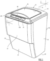
- a centrifugal separator such as a spin dryer
- the dryer 10 includes side panels 16, 18, an upper front panel 22 and a recessed lower front panel 24.
- the upper and lower front panels 22, 24 can be one unitary panel.
- a top panel 30 includes a recessed area 32 having an opening 33.
- the recessed area 32 and opening 33 are covered by a hinged lid 36.
- the top panel 30 also has an opening or recess 40 for a control panel 42.
- a rear panel 46 closes a back side of the dryer 10 and can be used to support the dryer 10 on a wall.
- a floor 48 substantially closes the bottom of the dryer.
- the panels 16, 18, 22, 24, 30 can be connected together by fasteners and/or by interlocking lips and/or clips or other means. Once the front panel 22 is removed, the top panel 30 can be removed. Also, once the front panels 22, 24 are removed access can be had to the electrical and mechanical components of the dryer 10.
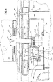
- FIGS 2-5 illustrate internal components of the dryer 10.
- a cylindrical basket 50 has a perforated, cylindrical sidewall 51 and a floor 52 and is supported on a driveshaft 56.
- the driveshaft 56 is coupled to a motor 60.
- a stationary chamber 53 includes a cylindrical sidewall 54 and a floor 55 substantially closing an open bottom end of the sidewall 54.
- the sidewall forms an open top end 57.
- the chamber 53 surrounds the basket 50.
- the floor 55 includes a central hole 55a to allow passage of the driveshaft 56.
- the motor 60 spins the driveshaft 56 and the basket 50.
- the motor is controlled by a motor control 60a.
- the driveshaft 56 passes through a guide or sleeve bearing 66 which is fastened to, or pressed into a plate 67.
- the plate 67 is mounted to an intermediate floor 68 via three circumferentially spaced-apart isolation mounts 69.
- the mounts can be elastomeric bushings, or the like.
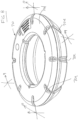
- a balance ring 70 is fastened around and upper portion of the basket 50 within the stationary chamber 53.
- the balance ring 70 has a sealed annular chamber 72 that contains a balance fluid, such as a saturated saline solution.
- the balance ring can be attached with fasteners or can have interacting formations to be snap fit over the basket.
- the balance ring 70 has an annular chamber 72 with a substantially triangular cross section defined by an upwardly and outwardly inclined outer wall 70b and a substantially vertical inner wall 70c.
- the annular chamber 72 is closed by a top wall 70d.
- Triangular ribs 70e are arranged spaced apart around the circumference of the ring 70.
- the ribs 70e extend radially inward from the outer wall 70b and terminate about halfway between the outer wall 70b and the inner wall 70c.
- the annular chamber 72 around the inner wall 70c, adjacent to the inner wall 70c, is continuously open, i.e., unbroken by the ribs 70e.
- the annular chamber 72 holds the fluid when stationary and as the ring spins, the fluid moves outward and upward along the outer wall 70b to increase inertia of the ring 70.
- the ribs 70e act as paddles to reduce the tendency of the fluid to remain stationary and slip with respect to the ring, i.e., the ribs 70e ensure the fluid moves rotationally with the ring 70 as it rotates.
- Figures 2-5 illustrate the driveshaft 56 includes an enlarged or shaped head portion 80 that fits into a recessed portion 82 of the floor 52 of the basket 50, and is fastened thereto by a fastener 84.
- the driveshaft 56 is guided in the guide or sleeve bearing 66.
- the plate 67 compresses vibration isolators 69 to the floor 68 via fasteners 71 extending between the plate 67 and the floor 68.
- the basket is easily removed for cleaning or maintenance by removal of the front panel 22 and the top panel 30 with the hinged lid 36, removal of the fastener 84 and withdrawing the basket 50 and balance ring 70 together vertically out through the open top end 57 of the stationary chamber 53, that is otherwise closed by the top cover 30 and lid 36.
- a mechanical floor 98 is hung from the intermediate floor 68 via sidewalls 98a, 98b.
- the motor 60 is fastened to the mechanical floor 98.
- the driveshaft 56 is connected to a flexible coupling 106 that is connected to an output shaft 108 of the motor 60.
- the coupling is shown in Figure 11 .
- the coupling 106 includes an upper clamp 106a that clamps the driveshaft 56 into an opening 106b via two fasteners fit through holes 106c, 106d.
- the coupling 106 includes a lower clamp 106e that clamps the motor output shaft 108 into an opening 106f via one or two fasteners fit through one or two holes 106g, 106h.
- a helical slot 106i between the two clamps 106a, 106e provides the flexible connection between the driveshaft 56 and the motor output shaft 108.
- a flange 112 is fixed between the helical slot 106i and the bottom clamp 106e.
- the output flange 112 is part of, or fastened to, coupling 106 to rotate therewith.
- a brake disc 118 is fastened to the output flange 112 to rotate therewith.
- a brake caliper 120 is fastened to the mechanical floor 98.
- the caliper 120 includes an upper housing 122a and a lower housing 122b, and upper and lower brake shoes 126, 128 arranged on opposite sides of the disc 118.
- a spring 130 acts to separate the brake shoes, by urging them away from the disc 118.
- An additional spring 131 acts to exert a downward force on the upper shoe 126 to compress the disc 118 between the two shoes 126, 128.
- a solenoid acts to release the brake
- a solenoid cylinder 132 when energized, exerts force to pivot a lever 133 about a fulcrum 133a to lift a piston 133b to overcome spring force from the spring 131 to relieve compression of the disc 118 from between his shoes 126, 128 to allow the disc 118 to rotate freely.
- the solenoid is not energized or powered, the brake shoes 126, 128 clamp the disc 118 under power of the spring 131 to stop the basket 50.
- the spring 131, the cylinder 132, the lever 133, and the fulcrum 133a are shown schematically. An alternate brake arrangement is shown and described below with respect to Figures 13-15 .
- a drain pipe 53a (shown dashed in Figure 6 ) allows water collected in the stationary chamber 53 to drain out of the dryer 10.
- a controller 144 ( Figure 12 ) is responsive to input instruction (e.g., start, stop, etc.) from a user through the control panel 42, such as through a touch screen keypad 145. Alternately, starting may be automatic upon closing the lid.
- An indicator 146 shows the status of the dryer, e.g., on, off, spinning, locked, maintenance needed, unbalanced load, etc. Particularly, a circular array of illuminators 148 cycle (on then off) sequentially around the circle to indicate that the dryer is spinning.
- one or more spring locks 147 hold the lid locked closed during operation.
- the spring lock 147 automatically locks the lid when it is closed.
- a "U" shaped strike 148 having a horizontal bottom portion 148a is attached to the lid 36.
- a latch 149 fabricated of spring steel or other material is attached to the top cover 30 at the location 149a by welding, fasteners or other means.
- the latch 149 may flex downward but not upward with respect to its rest position relative to the top cover 30.
- the horizontal bottom portion 148a passes below the tab 150, and the latch 149 springs back, engaging the bottom of the tab 150 with the top portion of the horizontal bottom portion 148a. Since the latch 149 is limited in upward movement by its proximity at point 151 to the top cover 30, any attempt to pry the lid open increases engagement of the latch and strike to prevent forced opening.
- the user pushes a control selection on the control panel 42, and a cable 152, within a stationary sheath 153 that is fixed to a back of the lock 147 at 153a, is pulled in the tension direction P along the cable 152 to bend the latch 149 clockwise ( Figure 17 ) about the attachment location 149a.
- the cable 152 is pulled with respect to the sheath 153 by a solenoid 155, fixed with the sheath to stationary structure of the dryer ( Figures 2 and 16 ), or other means to flex the latch 149 downward around the circular cross section of the horizontal bottom portion 148a.
- the lid moves downward slightly to accomplish this action, and the latch 149 is disengaged from the strike.
- the lid 36 is biased slightly open via a spring hinge 36a ( Figure 3 ) or other similar device which allows it to pop open when the latch is disengaged.
- the controller 144 operates the solenoid 155 to release the spring lock 147 to unlock the lid for opening the lid when operation has ceased.
- the controller 144 can be programmed to run the dryer through one cycle and then release the latch for the lid to pop open.
- a manual override by (maintenance personnel only) can be incorporated into the latch beneath the front cover.
- a lid closed or open sensor 154 ( Figure 3 ) is provided between the lid 36 and the cover 30 to communicate with the controller whether the lid is open or closed.
- the controller will prevent the dryer from starting if the lid is not closed and locked, and will prevent the lid from being opened during operation.
- the controller 144 can run the spin cycle according to a pre-selected routine or can change the pre-selected routine according to sensed conditions by controlling the motor control 60a. For example, if the load is unstable or unbalanced, sensed by a vibration sensor 156 (shown schematically in Figure 3 ) that signals the controller 144, the controller can cause the basket to be rotated in forward then reverse directions to attempt to re-arrange and balance the load. A similar cycle can be run to fix a jammed condition.
- a moisture sensor 158 (shown schematically in Figure 3 ) can be provided to sense the degree of moisture passing through the basket and communicate to the controller 144 which adjusts the cycle speed or duration accordingly.
- the controller can ramp up the speed of the basket during starting and ramp down the speed during stopping.
- the controller can spin the basket according to a pre-selected variation in basket speed and direction. For example, the controller can reverse or oscillate the spinning direction, i.e., spinning the basket back and forth in reverse rotational directions, to dislodge a jam or to pre-arrange and pre-balance the load before a spin cycle is started.
- the pre-selected variation in basket speed and direction can comprise a user selected routine.
- the controller can spin the basket according to a controlled variation in basket speed and direction depending on a sensed condition, such as vibration or moisture.
- the controller 144 can spin the basket 50 according to a controlled variation in basket speed and direction, comprising a routine wherein the basket 50 is brought up to operating speed through a region of increased basket vibration, and wherein the controller increases in spinning speed through the region slowly and once past the region, speed is increased to operating speed at a greater rate.
- the region of increased vibration can be sensed using a vibration sensor.
- FIG. 6 illustrates another aspect or enhancement of embodiments of the invention.
- An ultraviolet light 150 is mounted to an underside of the lid 36 and the ultraviolet light is energized between cycles. The ultraviolet light sterilizes surfaces within the basket.
- a similar arrangement can be used to intermittently spray a fragrance, liquid solution or disinfectant into the basket and/or the stationary chamber via a nozzle 152 controlled by the controller, fed from a fluid reservoir 153.
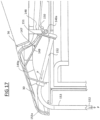
- FIG. 7 illustrates another aspect or enhancement of embodiments of the invention.
- the floor 52 of the basket 50 includes fan blades or fins 160 that circulate air in the basket 50 and the stationary chamber 53.
- Figure 12 illustrates the control system of the dryer 10.
- the controller 144 can receive signals from the moisture sensor 158, the vibration sensor 156, the lid lock 147 and operator input from the keypad 145.
- the controller 144 can send signals to the motor control 60a to adjust the speed, duration and direction of the motor 60.
- the controller 144 can send a signal to the brake solenoid 132 to release the brake upon starting of the spin dryer for an operating cycle.
- the controller 144 can signal the brake solenoid 132 to de-energize to stop the basket at the end of the operating cycle.
- the controller 144 can send signals to the display to indicate operation or status of the dryer or indicate trouble or faults in the dryer.
- the controller can send a signal to the UV light 150 and fluid dispenser 152 to intermittently treat the inside of the dryer.
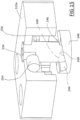
- FIG. 13 through 15 illustrated an alternate brake assembly 200.
- the assembly 200 includes the caliper 120 having upper and lower housings 122a, 122b which house upper brake shoe or pad 126 and lower brake shoe or pad 128, respectively.
- the housings 122a, 122b are fastened together and to the mechanical floor 98.
- the brake disc 118 is located partly between the upper and lower pads 126, 128.
- a lever 220 is fixed to a plunger 226 and rotationally connected to an L-shaped pin 228 at the distal end. The connection also allows vertical movement between the L-shaped pin 228 and the lever 220.
- the L-shaped pin is moved horizontally by a linear actuator, such as a solenoid actuator 230 when the L-shaped pin is extended out of, or retracted into, the solenoid actuator.
- a linear actuator such as a solenoid actuator 230 when the L-shaped pin is extended out of, or retracted into, the solenoid actuator.
- the lever 220 rotates and causes rotation of a plunger 236.
- the plunger 236 includes a cam disc 240 at a bottom end thereof.
- the cam disc 240 includes two cam tracks 244, 246 formed in rotational symmetry on opposite sides of the cam disc 240.
- Two roller bearings 254, 256 are held within the upper housing 122a, fixed in position but allowed to rotate about their axes and effectively ride on the respective cam tracks 244, 246 when the plunger 236 is rotated.
- the cam tracks each have an inclined surface 260 which causes the plunger 236 to be lowered when the plunger rotated about 1 ⁇ 4 turn or less, caused by the roller bearings 245, 256 in effect riding up the inclined surfaces 260.
- the cam disc 240 presses down on a pad plunger 266 which presses on the upper brake pad 126 to cause the upper and lower brake pads 126, 128 to pinch the brake disc therebetween, actuating the brake.
- Figure 15 illustrates the plunger 236 lowered for purpose of showing the cam disc 240 more clearly.
- the plunger 236 would be raised as shown in Figure 13 to be attached to the lever 220, and the roller bearings 245, 256 would be in contact with the cam track 244, 246 on each side of the cam disc 240.
- the solenoid 230 would have a spring return which would bias the pin 228 to an extended position to rotate the lever 220 clockwise (looking down on the lever in Figure 13 ) which would depress the plunger 236 to actuate the brake.
- An electrical signal to the solenoid would retract the pin 228 and rotate the lever 220 counter clockwise (looking down on the lever in Figure 13 ) to raise the plunger 236 and disengage the brake.
Landscapes
- Engineering & Computer Science (AREA)
- Health & Medical Sciences (AREA)
- Life Sciences & Earth Sciences (AREA)
- Molecular Biology (AREA)
- Mechanical Engineering (AREA)
- General Engineering & Computer Science (AREA)
- Textile Engineering (AREA)
- Centrifugal Separators (AREA)
Claims (15)
- Séparateur centrifuge (10), comprenant:a) un logement qui comprend une chambre stationnaire (53) ayant une paroi latérale (51) et un fond (55) ;b) un tambour (50) agencé pour tourner à l'intérieur de la chambre stationnaire (53), le tambour (50) ayant une paroi latérale périphérique perforée;c) un moteur (60) disposé sous le fond (55), le moteur (60) ayant un carter de moteur et un arbre de sortie (108) ;d) un arbre d'entraînement (56) relié à l'arbre de sortie (108), l'arbre d'entraînement traversant le fond (55) et étant relié au tambour (50),caractérisé en ce quee) le boîtier comprend également un plancher mécanique (98) au-dessous du plancher inférieur (55); et l'arbre d'entraînement (56) est relié à l'arbre de sortie (108) par l'intermédiaire d'un accouplement flexible (106) ; et le carter de moteur est fixé au plancher mécanique (98), etf) le séparateur centrifuge (10) comprend un anneau d'équilibrage (70) ayant une chambre annulaire (72) contenant un fluide d'équilibrage, l'anneau d'équilibrage (70) étant monté sur un extérieur du tambour (50) pour tourner avec celui-ci.
- Séparateur centrifuge selon la revendication 1, caractérisé en ce que le séparateur centrifuge (10) comprend un contrôleur (144) et un indicateur (146), le contrôleur (144) démarrant le cycle en verrouillant le couvercle fermé, l'indicateur (146) utilisant une image pour indiquer que le tambour (50) tourne.
- Séparateur centrifuge selon la revendication 1, caractérisé en ce que le séparateur centrifuge (10) comprend un disque de frein (118) fixé pour tourner avec l'arbre d'entraînement (56), et un étrier de frein (120) fixé par rapport à la chambre stationnaire (53) et pouvant fonctionner sur le disque de frein (118) pour arrêter la rotation du tambour (50).
- Séparateur centrifuge (10) selon la revendication 3, caractérisé en ce quea) le moteur (60) comprend un moteur à courant continu, oub) l'étrier de frein (120) comprend des sabots de frein qui peuvent être engagés sur des faces opposées du disque de frein (118).
- Séparateur centrifuge (10) selon la revendication 1, comprenant un panneau de commande ayant un indicateur (146) qui fait circuler des signaux lumineux autour d'un chemin pour indiquer la rotation du tambour (50).
- Séparateur centrifuge (10) selon la revendication 2, comprenant un distributeur de fluide commandé par le contrôleur (144) pour distribuer du fluide par intermittence dans la chambre stationnaire (53).
- Séparateur centrifuge (10) selon la revendication 2, comprenant une lumière ultraviolette (150) à l'intérieur de la chambre stationnaire (53) qui est commandée par le contrôleur (144) pour illuminer par intermittence.
- Séparateur centrifuge (10) selon la revendication 1, comprenant des pales (160) disposées sur le fond du tambour (50) pour tourner à l'intérieur du séparateur (10) afin de faire circuler l'air à l'intérieur du séparateur (10).
- Séparateur centrifuge (10) selon la revendication 2, comprenant un distributeur (152) commandé par le contrôleur (144) pour distribuer un liquide ou un gaz par intermittence dans la chambre stationnaire (53).
- Séparateur centrifuge (10) selon la revendication 2, caractérisé en ce que l'image se déplace autour d'un chemin continu lorsque le tambour (50) tourne.
- Séparateur centrifuge (10) selon la revendication 2, caractérisé en ce que le contrôleur (144) est configuré pour augmenter progressivement la vitesse du tambour (50) pendant le démarrage et pour diminuer progressivement la vitesse pendant l'arrêt.
- Séparateur centrifuge (10) selon la revendication 2, caractérisé en ce que le contrôleur (144) fait tourner le tambour (50) selon une variation présélectionnée de la vitesse et de la direction du tambour.
- Séparateur centrifuge (10) selon la revendication 2, caractérisé en ce que le contrôleur (144) fait tourner le tambour (50), en oscillant d'avant en arrière dans des sens de rotation inverses.
- Séparateur centrifuge selon la revendication 2, caractérisé en ce que le contrôleur (144) fait tourner le tambour (50) selon une variation présélectionnée de la vitesse et de la direction du tambour, dans lequel la variation présélectionnée de la vitesse et de la direction du tambour comprend une routine sélectionnée par l'utilisateur.
- Séparateur centrifuge (10) selon la revendication 2, caractérisé en ce que le contrôleur (144) fait tourner le tambour (50) selon une variation contrôlée de la vitesse et de la direction du tambour, comprenant une routine dans laquelle le tambour (50) est amené à la vitesse de fonctionnement à travers une région de vibration accrue du tambour, et dans laquelle la vitesse de rotation du tambour (50) est augmentée à travers la région lentement et une fois la région passée, la vitesse de rotation du tambour est augmentée à la vitesse de fonctionnement à un taux plus élevé.
Applications Claiming Priority (2)
| Application Number | Priority Date | Filing Date | Title |
|---|---|---|---|
| US14/555,081 US10024597B2 (en) | 2014-11-26 | 2014-11-26 | Centrifugal separator |
| PCT/US2015/062789 WO2016086198A1 (fr) | 2014-11-26 | 2015-11-25 | Séparateur centrifuge |
Publications (3)
| Publication Number | Publication Date |
|---|---|
| EP3224400A1 EP3224400A1 (fr) | 2017-10-04 |
| EP3224400A4 EP3224400A4 (fr) | 2018-12-05 |
| EP3224400B1 true EP3224400B1 (fr) | 2023-03-29 |
Family
ID=56009861
Family Applications (1)
| Application Number | Title | Priority Date | Filing Date |
|---|---|---|---|
| EP15863811.4A Active EP3224400B1 (fr) | 2014-11-26 | 2015-11-25 | Séparateur centrifuge |
Country Status (7)
| Country | Link |
|---|---|
| US (2) | US10024597B2 (fr) |
| EP (1) | EP3224400B1 (fr) |
| CN (1) | CN107109764B (fr) |
| AU (1) | AU2015353418B2 (fr) |
| CA (1) | CA2968971C (fr) |
| ES (1) | ES2942325T3 (fr) |
| WO (1) | WO2016086198A1 (fr) |
Families Citing this family (6)
| Publication number | Priority date | Publication date | Assignee | Title |
|---|---|---|---|---|
| TWM482727U (zh) * | 2014-02-14 | 2014-07-21 | Great Eagle Technologies Co Ltd | 毛巾脫乾器 |
| CN107855227B (zh) * | 2017-11-20 | 2019-10-11 | 台州锐祥机械设备有限公司 | 一种具有自动化控制的工业生产用脱水装置 |
| US11085147B2 (en) | 2018-09-27 | 2021-08-10 | Whirlpool Corporation | Sanitation device |
| CN110251974B (zh) * | 2019-06-23 | 2021-05-25 | 安徽江锐新材料有限公司 | 一种无热型多方向同轴离心式水性漆干燥设备 |
| CN110986494A (zh) * | 2019-12-18 | 2020-04-10 | 咸宁市三山川茶业股份有限公司 | 一种可监控的茶叶脱水装置 |
| CN112268416A (zh) * | 2020-10-22 | 2021-01-26 | 安龙县绿宇农特产农民专业合作社 | 一种便于糯米进行清洗的粽子生产用沥干装置 |
Family Cites Families (36)
| Publication number | Priority date | Publication date | Assignee | Title |
|---|---|---|---|---|
| US2533722A (en) * | 1943-07-14 | 1950-12-12 | J G De Remer Res Corp | Balancing centrifugal drying and washing machine |
| US3391469A (en) * | 1965-12-09 | 1968-07-09 | San Kenteen Corp | Centrifugal dryer |
| US3742738A (en) * | 1971-07-26 | 1973-07-03 | Mc Graw Edison Co | Laundry handling system and equipment |
| US4044626A (en) | 1975-04-18 | 1977-08-30 | Sanyo Electric Co., Ltd. | Balancing ring of centrifugal extractor |
| US4328600A (en) * | 1979-05-15 | 1982-05-11 | General Electric Company | Washing machine |
| US4412390A (en) * | 1980-09-23 | 1983-11-01 | Grant William P | Centrifugal spin air dryer |
| US4646545A (en) | 1985-04-26 | 1987-03-03 | Whirlpool Corporation | Balancing ring and attachment means for automatic washer |
| US4656847A (en) | 1985-08-19 | 1987-04-14 | Whirlpool Corporation | Automatic washer balancing ring with spring clip attachment means |
| US4742624A (en) * | 1986-08-27 | 1988-05-10 | Extractor Corporation | Spin dryer |
| JP3297073B2 (ja) | 1992-03-31 | 2002-07-02 | 株式会社東芝 | 洗濯機 |
| US5694112A (en) * | 1994-12-12 | 1997-12-02 | Grote Industries, Inc. | Solid state rotary apparent beacon |
| IT1271782B (it) * | 1994-12-21 | 1997-06-09 | Whirlpool Italia | Metodo e disposizione per ottenere il bilanciamento del carico nelle macchine lavabiancheria |
| US5887456A (en) * | 1995-08-30 | 1999-03-30 | Sharp Kabushiki Kaisha | Drum type drying/washing machine |
| US5765404A (en) | 1995-11-17 | 1998-06-16 | Whirlpool Corporation | Balance ring attachment in an automatic washer |
| JP3022483B2 (ja) | 1998-05-28 | 2000-03-21 | 松下電器産業株式会社 | 洗濯機 |
| US5974681A (en) * | 1997-09-10 | 1999-11-02 | Speedfam-Ipec Corp. | Apparatus for spin drying a workpiece |
| JP3605067B2 (ja) * | 2001-11-14 | 2004-12-22 | 三洋電機株式会社 | ドラム式洗濯乾燥機 |
| KR100529888B1 (ko) * | 2003-02-20 | 2005-11-22 | 엘지전자 주식회사 | 모터 및 그 모터가 설치된 세탁기 |
| US6877248B1 (en) | 2004-03-05 | 2005-04-12 | Gregory N. Cross | Clothes dryer with ultraviolet light |
| KR101022217B1 (ko) * | 2004-05-27 | 2011-03-17 | 삼성전자주식회사 | 탈취수단을 구비한 세탁기 및 그 제어방법 |
| EP1773186A4 (fr) * | 2004-07-08 | 2009-08-12 | Deborah Schenberger | Systeme et dispositif pour le controle de souche |
| KR101049126B1 (ko) * | 2004-07-20 | 2011-07-14 | 엘지전자 주식회사 | 컨트롤 패널의 엘이디 윈도우 구조 |
| EP1932962B1 (fr) * | 2005-10-07 | 2012-10-24 | Sanyo Electric Co., Ltd. | Sèche-linge |
| KR101253630B1 (ko) * | 2006-03-09 | 2013-04-10 | 엘지전자 주식회사 | 건조기의 제어방법 |
| CN2934309Y (zh) * | 2006-05-31 | 2007-08-15 | 肇庆市自动化仪表二厂有限公司 | 全自动洗衣机减速离合器的动力输出装置 |
| KR101448625B1 (ko) * | 2007-12-31 | 2014-10-08 | 엘지전자 주식회사 | 세탁기의 제어방법 |
| US20090272004A1 (en) * | 2008-05-01 | 2009-11-05 | Whirlpool Corporation | Intelligent dispensing in a laundry appliance |
| US8955232B2 (en) * | 2008-06-27 | 2015-02-17 | Cube Investments Limited | Laundry dryer/venting system interlock |
| JP2010057822A (ja) * | 2008-09-05 | 2010-03-18 | Hitachi Appliances Inc | ドラム式洗濯機 |
| US20120151686A1 (en) * | 2009-08-27 | 2012-06-21 | Jae Hyuk Jang | Control method of laundry machine |
| US9010159B2 (en) * | 2010-04-13 | 2015-04-21 | Whirlpool Corporation | Laundry treating appliance with tub ring |
| US9833121B2 (en) * | 2011-08-15 | 2017-12-05 | Illinois Tool Works, Inc. | Dishwasher with self-sealing vent fan |
| US9695538B2 (en) * | 2012-03-12 | 2017-07-04 | Haier Us Appliance Solutions, Inc. | Balance ring and fastener guide for a washing machine |
| CN104246050B (zh) * | 2012-04-23 | 2016-09-21 | 松下知识产权经营株式会社 | 滚筒式洗衣机 |
| KR102024086B1 (ko) * | 2012-12-28 | 2019-09-23 | 엘지전자 주식회사 | 세탁기 및 세탁기 제어방법 |
| BE1021138B1 (nl) * | 2013-03-27 | 2016-01-05 | Cnh Industrial Belgium Nv | Landbouwbalenpers met hulpmotor |
-
2014
- 2014-11-26 US US14/555,081 patent/US10024597B2/en active Active
-
2015
- 2015-11-25 CN CN201580071270.4A patent/CN107109764B/zh active Active
- 2015-11-25 AU AU2015353418A patent/AU2015353418B2/en active Active
- 2015-11-25 CA CA2968971A patent/CA2968971C/fr active Active
- 2015-11-25 ES ES15863811T patent/ES2942325T3/es active Active
- 2015-11-25 EP EP15863811.4A patent/EP3224400B1/fr active Active
- 2015-11-25 WO PCT/US2015/062789 patent/WO2016086198A1/fr not_active Ceased
-
2018
- 2018-06-26 US US16/018,994 patent/US20180313605A1/en not_active Abandoned
Also Published As
| Publication number | Publication date |
|---|---|
| US20160146536A1 (en) | 2016-05-26 |
| CA2968971A1 (fr) | 2016-06-02 |
| US20180313605A1 (en) | 2018-11-01 |
| ES2942325T3 (es) | 2023-05-31 |
| CN107109764A (zh) | 2017-08-29 |
| EP3224400A1 (fr) | 2017-10-04 |
| US10024597B2 (en) | 2018-07-17 |
| AU2015353418B2 (en) | 2020-05-28 |
| AU2015353418A1 (en) | 2017-06-29 |
| CA2968971C (fr) | 2023-07-11 |
| CN107109764B (zh) | 2019-12-17 |
| WO2016086198A1 (fr) | 2016-06-02 |
| EP3224400A4 (fr) | 2018-12-05 |
Similar Documents
| Publication | Publication Date | Title |
|---|---|---|
| EP3224400B1 (fr) | Séparateur centrifuge | |
| KR950002007B1 (ko) | 세탁기 | |
| KR20010086011A (ko) | 상부적재식 세탁기 | |
| US20140268648A1 (en) | Domestic appliance including piezoelectric components | |
| EP1298242A1 (fr) | Améliorations pour l'ouverture du tambour et de la cuve d'une machine à laver à chargenment par le dessus | |
| JPH02305593A (ja) | 全自動洗濯・乾燥機 | |
| JP2008207142A (ja) | 遠心分離機 | |
| CN101384764A (zh) | 洗衣机 | |
| US11608582B2 (en) | Washing machine | |
| JP6851587B2 (ja) | 洗濯機 | |
| WO2018228804A1 (fr) | Lave-linge et son procédé de commande | |
| CA1107979A (fr) | Dispositif antiraclage sur embrayage de roue dentee | |
| JP6868241B2 (ja) | 洗濯機 | |
| AU2007232558A1 (en) | Laundry machine with lost motion clutch | |
| WO2008018350A1 (fr) | Machine à laver | |
| KR20160099247A (ko) | 의류 관리기 | |
| JP4337601B2 (ja) | 脱水機 | |
| JP2013226484A (ja) | 除湿機 | |
| KR100564737B1 (ko) | 휴대용 부탄가스를 사용하는 의류건조기 | |
| US1224888A (en) | Centrifugal extractor. | |
| JPH04152985A (ja) | 洗濯機の排水制御方法 | |
| JPH04361797A (ja) | 扉のロック機構 | |
| KR20190129208A (ko) | 세탁기 | |
| JPH0663287A (ja) | 洗濯機のスイッチ装置 | |
| KR101037154B1 (ko) | 세탁기의 제동 제어 방법 |
Legal Events
| Date | Code | Title | Description |
|---|---|---|---|
| STAA | Information on the status of an ep patent application or granted ep patent |
Free format text: STATUS: THE INTERNATIONAL PUBLICATION HAS BEEN MADE |
|
| PUAI | Public reference made under article 153(3) epc to a published international application that has entered the european phase |
Free format text: ORIGINAL CODE: 0009012 |
|
| STAA | Information on the status of an ep patent application or granted ep patent |
Free format text: STATUS: REQUEST FOR EXAMINATION WAS MADE |
|
| 17P | Request for examination filed |
Effective date: 20170623 |
|
| AK | Designated contracting states |
Kind code of ref document: A1 Designated state(s): AL AT BE BG CH CY CZ DE DK EE ES FI FR GB GR HR HU IE IS IT LI LT LU LV MC MK MT NL NO PL PT RO RS SE SI SK SM TR |
|
| AX | Request for extension of the european patent |
Extension state: BA ME |
|
| RIN1 | Information on inventor provided before grant (corrected) |
Inventor name: HOFFMAN, LINDSAY A. Inventor name: SLOWIK, STEVEN C. Inventor name: NOWAK, AMBER D. Inventor name: MILLER, BENJAMIN D. Inventor name: HOFFMAN, HUGH J. Inventor name: SCOLA, MICHAEL J. |
|
| DAV | Request for validation of the european patent (deleted) | ||
| DAX | Request for extension of the european patent (deleted) | ||
| RIC1 | Information provided on ipc code assigned before grant |
Ipc: D06F 49/04 20060101ALI20180719BHEP Ipc: D06F 49/00 20060101AFI20180719BHEP Ipc: D06F 49/06 20060101ALN20180719BHEP Ipc: D06F 37/24 20060101ALN20180719BHEP |
|
| A4 | Supplementary search report drawn up and despatched |
Effective date: 20181029 |
|
| RIC1 | Information provided on ipc code assigned before grant |
Ipc: D06F 49/06 20060101ALN20181023BHEP Ipc: D06F 49/04 20060101ALI20181023BHEP Ipc: D06F 37/24 20060101ALN20181023BHEP Ipc: D06F 49/00 20060101AFI20181023BHEP |
|
| STAA | Information on the status of an ep patent application or granted ep patent |
Free format text: STATUS: EXAMINATION IS IN PROGRESS |
|
| 17Q | First examination report despatched |
Effective date: 20190826 |
|
| GRAP | Despatch of communication of intention to grant a patent |
Free format text: ORIGINAL CODE: EPIDOSNIGR1 |
|
| STAA | Information on the status of an ep patent application or granted ep patent |
Free format text: STATUS: GRANT OF PATENT IS INTENDED |
|
| RIC1 | Information provided on ipc code assigned before grant |
Ipc: D06F 37/24 20060101ALN20221019BHEP Ipc: D06F 49/06 20060101ALN20221019BHEP Ipc: F26B 5/08 20060101ALI20221019BHEP Ipc: D06F 49/04 20060101ALI20221019BHEP Ipc: D06F 49/00 20060101AFI20221019BHEP |
|
| INTG | Intention to grant announced |
Effective date: 20221116 |
|
| GRAS | Grant fee paid |
Free format text: ORIGINAL CODE: EPIDOSNIGR3 |
|
| GRAA | (expected) grant |
Free format text: ORIGINAL CODE: 0009210 |
|
| STAA | Information on the status of an ep patent application or granted ep patent |
Free format text: STATUS: THE PATENT HAS BEEN GRANTED |
|
| AK | Designated contracting states |
Kind code of ref document: B1 Designated state(s): AL AT BE BG CH CY CZ DE DK EE ES FI FR GB GR HR HU IE IS IT LI LT LU LV MC MK MT NL NO PL PT RO RS SE SI SK SM TR |
|
| REG | Reference to a national code |
Ref country code: GB Ref legal event code: FG4D |
|
| REG | Reference to a national code |
Ref country code: CH Ref legal event code: EP |
|
| REG | Reference to a national code |
Ref country code: DE Ref legal event code: R096 Ref document number: 602015082995 Country of ref document: DE |
|
| REG | Reference to a national code |
Ref country code: AT Ref legal event code: REF Ref document number: 1556726 Country of ref document: AT Kind code of ref document: T Effective date: 20230415 |
|
| REG | Reference to a national code |
Ref country code: IE Ref legal event code: FG4D |
|
| REG | Reference to a national code |
Ref country code: SE Ref legal event code: TRGR |
|
| REG | Reference to a national code |
Ref country code: ES Ref legal event code: FG2A Ref document number: 2942325 Country of ref document: ES Kind code of ref document: T3 Effective date: 20230531 |
|
| REG | Reference to a national code |
Ref country code: LT Ref legal event code: MG9D |
|
| PG25 | Lapsed in a contracting state [announced via postgrant information from national office to epo] |
Ref country code: RS Free format text: LAPSE BECAUSE OF FAILURE TO SUBMIT A TRANSLATION OF THE DESCRIPTION OR TO PAY THE FEE WITHIN THE PRESCRIBED TIME-LIMIT Effective date: 20230329 Ref country code: NO Free format text: LAPSE BECAUSE OF FAILURE TO SUBMIT A TRANSLATION OF THE DESCRIPTION OR TO PAY THE FEE WITHIN THE PRESCRIBED TIME-LIMIT Effective date: 20230629 Ref country code: LV Free format text: LAPSE BECAUSE OF FAILURE TO SUBMIT A TRANSLATION OF THE DESCRIPTION OR TO PAY THE FEE WITHIN THE PRESCRIBED TIME-LIMIT Effective date: 20230329 Ref country code: LT Free format text: LAPSE BECAUSE OF FAILURE TO SUBMIT A TRANSLATION OF THE DESCRIPTION OR TO PAY THE FEE WITHIN THE PRESCRIBED TIME-LIMIT Effective date: 20230329 Ref country code: HR Free format text: LAPSE BECAUSE OF FAILURE TO SUBMIT A TRANSLATION OF THE DESCRIPTION OR TO PAY THE FEE WITHIN THE PRESCRIBED TIME-LIMIT Effective date: 20230329 |
|
| REG | Reference to a national code |
Ref country code: NL Ref legal event code: MP Effective date: 20230329 |
|
| REG | Reference to a national code |
Ref country code: AT Ref legal event code: MK05 Ref document number: 1556726 Country of ref document: AT Kind code of ref document: T Effective date: 20230329 |
|
| PG25 | Lapsed in a contracting state [announced via postgrant information from national office to epo] |
Ref country code: NL Free format text: LAPSE BECAUSE OF FAILURE TO SUBMIT A TRANSLATION OF THE DESCRIPTION OR TO PAY THE FEE WITHIN THE PRESCRIBED TIME-LIMIT Effective date: 20230329 Ref country code: GR Free format text: LAPSE BECAUSE OF FAILURE TO SUBMIT A TRANSLATION OF THE DESCRIPTION OR TO PAY THE FEE WITHIN THE PRESCRIBED TIME-LIMIT Effective date: 20230630 Ref country code: FI Free format text: LAPSE BECAUSE OF FAILURE TO SUBMIT A TRANSLATION OF THE DESCRIPTION OR TO PAY THE FEE WITHIN THE PRESCRIBED TIME-LIMIT Effective date: 20230329 |
|
| PG25 | Lapsed in a contracting state [announced via postgrant information from national office to epo] |
Ref country code: SM Free format text: LAPSE BECAUSE OF FAILURE TO SUBMIT A TRANSLATION OF THE DESCRIPTION OR TO PAY THE FEE WITHIN THE PRESCRIBED TIME-LIMIT Effective date: 20230329 Ref country code: RO Free format text: LAPSE BECAUSE OF FAILURE TO SUBMIT A TRANSLATION OF THE DESCRIPTION OR TO PAY THE FEE WITHIN THE PRESCRIBED TIME-LIMIT Effective date: 20230329 Ref country code: PT Free format text: LAPSE BECAUSE OF FAILURE TO SUBMIT A TRANSLATION OF THE DESCRIPTION OR TO PAY THE FEE WITHIN THE PRESCRIBED TIME-LIMIT Effective date: 20230731 Ref country code: EE Free format text: LAPSE BECAUSE OF FAILURE TO SUBMIT A TRANSLATION OF THE DESCRIPTION OR TO PAY THE FEE WITHIN THE PRESCRIBED TIME-LIMIT Effective date: 20230329 Ref country code: AT Free format text: LAPSE BECAUSE OF FAILURE TO SUBMIT A TRANSLATION OF THE DESCRIPTION OR TO PAY THE FEE WITHIN THE PRESCRIBED TIME-LIMIT Effective date: 20230329 |
|
| PG25 | Lapsed in a contracting state [announced via postgrant information from national office to epo] |
Ref country code: SK Free format text: LAPSE BECAUSE OF FAILURE TO SUBMIT A TRANSLATION OF THE DESCRIPTION OR TO PAY THE FEE WITHIN THE PRESCRIBED TIME-LIMIT Effective date: 20230329 Ref country code: PL Free format text: LAPSE BECAUSE OF FAILURE TO SUBMIT A TRANSLATION OF THE DESCRIPTION OR TO PAY THE FEE WITHIN THE PRESCRIBED TIME-LIMIT Effective date: 20230329 Ref country code: IS Free format text: LAPSE BECAUSE OF FAILURE TO SUBMIT A TRANSLATION OF THE DESCRIPTION OR TO PAY THE FEE WITHIN THE PRESCRIBED TIME-LIMIT Effective date: 20230729 |
|
| REG | Reference to a national code |
Ref country code: DE Ref legal event code: R097 Ref document number: 602015082995 Country of ref document: DE |
|
| PG25 | Lapsed in a contracting state [announced via postgrant information from national office to epo] |
Ref country code: DK Free format text: LAPSE BECAUSE OF FAILURE TO SUBMIT A TRANSLATION OF THE DESCRIPTION OR TO PAY THE FEE WITHIN THE PRESCRIBED TIME-LIMIT Effective date: 20230329 |
|
| PLBE | No opposition filed within time limit |
Free format text: ORIGINAL CODE: 0009261 |
|
| STAA | Information on the status of an ep patent application or granted ep patent |
Free format text: STATUS: NO OPPOSITION FILED WITHIN TIME LIMIT |
|
| 26N | No opposition filed |
Effective date: 20240103 |
|
| PG25 | Lapsed in a contracting state [announced via postgrant information from national office to epo] |
Ref country code: SI Free format text: LAPSE BECAUSE OF FAILURE TO SUBMIT A TRANSLATION OF THE DESCRIPTION OR TO PAY THE FEE WITHIN THE PRESCRIBED TIME-LIMIT Effective date: 20230329 |
|
| PG25 | Lapsed in a contracting state [announced via postgrant information from national office to epo] |
Ref country code: SI Free format text: LAPSE BECAUSE OF FAILURE TO SUBMIT A TRANSLATION OF THE DESCRIPTION OR TO PAY THE FEE WITHIN THE PRESCRIBED TIME-LIMIT Effective date: 20230329 |
|
| REG | Reference to a national code |
Ref country code: CH Ref legal event code: PL |
|
| PG25 | Lapsed in a contracting state [announced via postgrant information from national office to epo] |
Ref country code: MC Free format text: LAPSE BECAUSE OF FAILURE TO SUBMIT A TRANSLATION OF THE DESCRIPTION OR TO PAY THE FEE WITHIN THE PRESCRIBED TIME-LIMIT Effective date: 20230329 |
|
| PG25 | Lapsed in a contracting state [announced via postgrant information from national office to epo] |
Ref country code: LU Free format text: LAPSE BECAUSE OF NON-PAYMENT OF DUE FEES Effective date: 20231125 |
|
| PG25 | Lapsed in a contracting state [announced via postgrant information from national office to epo] |
Ref country code: CH Free format text: LAPSE BECAUSE OF NON-PAYMENT OF DUE FEES Effective date: 20231130 |
|
| PG25 | Lapsed in a contracting state [announced via postgrant information from national office to epo] |
Ref country code: MC Free format text: LAPSE BECAUSE OF FAILURE TO SUBMIT A TRANSLATION OF THE DESCRIPTION OR TO PAY THE FEE WITHIN THE PRESCRIBED TIME-LIMIT Effective date: 20230329 Ref country code: LU Free format text: LAPSE BECAUSE OF NON-PAYMENT OF DUE FEES Effective date: 20231125 Ref country code: CH Free format text: LAPSE BECAUSE OF NON-PAYMENT OF DUE FEES Effective date: 20231130 |
|
| REG | Reference to a national code |
Ref country code: BE Ref legal event code: MM Effective date: 20231130 |
|
| PG25 | Lapsed in a contracting state [announced via postgrant information from national office to epo] |
Ref country code: BE Free format text: LAPSE BECAUSE OF NON-PAYMENT OF DUE FEES Effective date: 20231130 |
|
| PG25 | Lapsed in a contracting state [announced via postgrant information from national office to epo] |
Ref country code: BE Free format text: LAPSE BECAUSE OF NON-PAYMENT OF DUE FEES Effective date: 20231130 |
|
| PG25 | Lapsed in a contracting state [announced via postgrant information from national office to epo] |
Ref country code: BG Free format text: LAPSE BECAUSE OF FAILURE TO SUBMIT A TRANSLATION OF THE DESCRIPTION OR TO PAY THE FEE WITHIN THE PRESCRIBED TIME-LIMIT Effective date: 20230329 |
|
| PG25 | Lapsed in a contracting state [announced via postgrant information from national office to epo] |
Ref country code: BG Free format text: LAPSE BECAUSE OF FAILURE TO SUBMIT A TRANSLATION OF THE DESCRIPTION OR TO PAY THE FEE WITHIN THE PRESCRIBED TIME-LIMIT Effective date: 20230329 |
|
| PGFP | Annual fee paid to national office [announced via postgrant information from national office to epo] |
Ref country code: IE Payment date: 20241126 Year of fee payment: 10 |
|
| PGFP | Annual fee paid to national office [announced via postgrant information from national office to epo] |
Ref country code: IT Payment date: 20241128 Year of fee payment: 10 Ref country code: ES Payment date: 20241210 Year of fee payment: 10 |
|
| PGFP | Annual fee paid to national office [announced via postgrant information from national office to epo] |
Ref country code: SE Payment date: 20241126 Year of fee payment: 10 |
|
| PG25 | Lapsed in a contracting state [announced via postgrant information from national office to epo] |
Ref country code: CY Free format text: LAPSE BECAUSE OF FAILURE TO SUBMIT A TRANSLATION OF THE DESCRIPTION OR TO PAY THE FEE WITHIN THE PRESCRIBED TIME-LIMIT; INVALID AB INITIO Effective date: 20151125 |
|
| PG25 | Lapsed in a contracting state [announced via postgrant information from national office to epo] |
Ref country code: HU Free format text: LAPSE BECAUSE OF FAILURE TO SUBMIT A TRANSLATION OF THE DESCRIPTION OR TO PAY THE FEE WITHIN THE PRESCRIBED TIME-LIMIT; INVALID AB INITIO Effective date: 20151125 |
|
| PG25 | Lapsed in a contracting state [announced via postgrant information from national office to epo] |
Ref country code: TR Free format text: LAPSE BECAUSE OF FAILURE TO SUBMIT A TRANSLATION OF THE DESCRIPTION OR TO PAY THE FEE WITHIN THE PRESCRIBED TIME-LIMIT Effective date: 20230329 |
|
| PGFP | Annual fee paid to national office [announced via postgrant information from national office to epo] |
Ref country code: DE Payment date: 20251126 Year of fee payment: 11 |
|
| PGFP | Annual fee paid to national office [announced via postgrant information from national office to epo] |
Ref country code: GB Payment date: 20251120 Year of fee payment: 11 |
|
| PGFP | Annual fee paid to national office [announced via postgrant information from national office to epo] |
Ref country code: FR Payment date: 20251124 Year of fee payment: 11 |
|
| PGFP | Annual fee paid to national office [announced via postgrant information from national office to epo] |
Ref country code: CZ Payment date: 20251119 Year of fee payment: 11 |