EP3225732B1 - Dispositif d'amortissement pour un dispositif de chargement d'article en tissu automatisé - Google Patents
Dispositif d'amortissement pour un dispositif de chargement d'article en tissu automatisé Download PDFInfo
- Publication number
- EP3225732B1 EP3225732B1 EP15862854.5A EP15862854A EP3225732B1 EP 3225732 B1 EP3225732 B1 EP 3225732B1 EP 15862854 A EP15862854 A EP 15862854A EP 3225732 B1 EP3225732 B1 EP 3225732B1
- Authority
- EP
- European Patent Office
- Prior art keywords
- cloth
- feeding conveyor
- left sides
- feeding
- end portions
- Prior art date
- Legal status (The legal status is an assumption and is not a legal conclusion. Google has not performed a legal analysis and makes no representation as to the accuracy of the status listed.)
- Active
Links
Images




Classifications
-
- D—TEXTILES; PAPER
- D06—TREATMENT OF TEXTILES OR THE LIKE; LAUNDERING; FLEXIBLE MATERIALS NOT OTHERWISE PROVIDED FOR
- D06F—LAUNDERING, DRYING, IRONING, PRESSING OR FOLDING TEXTILE ARTICLES
- D06F67/00—Details of ironing machines provided for in groups D06F61/00, D06F63/00, or D06F65/00
- D06F67/04—Arrangements for feeding or spreading the linen
Definitions
- the present invention relates to an automatic cloth feeder comprising a buffering device, wherein cloth is introduced to a feeding conveyor at a substantially central portion in a carrying direction, right and left trailing end portions thereof are detected by crumpling the cloth from the right and left, and the right and left trailing end portions are held by a deposition section.
- An automatic feeding method is divided into two main types of methods.
- One is a method in which one end or both ends of cloth are searched for so as to be fed, and the other one is a method in which both ends of cloth are automatically searched for and are automatically spread when a side of the cloth is fed onto the carrying conveyor.
- the main stream is the former method because the latter method has low stability and quality.
- the former method is absolutely advantageous.
- the latter method rather has room for improvement, achieving a prospect of being superior to the former method when improved.
- As the latter method there is the invention disclosed in JP-A-10-5500 .
- JP 2011-36312 A discloses an automatic cloth feeder comprising a feeder conveyor, a deposition section comprising catch means to catch and hold a trailing end portion of the cloth detected by a sensor, and a buffering device comprising a cloth supply section provided at a preceding stage of the feeding conveyor and configured to move upward to the feeding conveyor from below to introduce the cloth to the feeding conveyor, wherein the cloth supply section is equipped with a clamp
- the present invention has been made taking the foregoing circumstances into consideration.
- An object thereof is to provide a buffering device in an automatic cloth feeder including a cloth standby section in which cloth stands by temporarily, and allowing the cloth to be accumulated.
- Another object of the present invention is to provide a cloth spreading device in which the cloth standby section is arranged before a feeding conveyor and a deposition section, and the number of cloth pieces to be accumulated can be increased and decreased.
- the present invention discloses an automatic cloth feeder as defined in claim 1 Cloth is considered as a target in the device of the present invention. However, it is natural that the cloth includes clothing as well.
- the automatic cloth feeder applied with the buffering device of the present invention adopts a method in which a side of cloth is fed onto the carrying conveyor and both ends of cloth are automatically searched for and are automatically spread.
- the cloth is introduced to the feeding conveyor at the substantially central portion in the carrying direction and is carried to a predetermined position on the front face of the feeder main body, both the right and left portions of cloth are crumpled in a central portion direction of the cloth, thereby performing deposition from the right and left trailing end portions of the cloth.
- both the right and left portions of the cloth drooping on the right and left sides of the feeding conveyor are crumpled (gathered) in the central portion direction of the cloth, and the right and left trailing end portions are held by a member provided on the feeder side.
- the cloth standby section in which the cloth to be carried stands by temporarily at the preceding stage of the feeding conveyor or at the following stage thereof is devised.
- the cloth supply section is means for supplying the cloth to perform automatic feeding. Therefore, the cloth supply section itself constitutes the cloth standby section.
- the cloth standby section causes the cloth to stand by temporarily without congesting feeding of the cloth which flows at a substantially regular speed and is combined as buffering means by a type of retention means. Having the feeding conveyor as a fiducial point, the cloth standby section can be arranged at the preceding stage, or at both the preceding stage and the following stage at the same time.
- the straightening unit can be provided at the following stage of the feeding conveyor in order to pull cloth held in the deposition section to the right and left sides so as to achieve a straightened state, and the straightening unit can be arranged at a plurality of places so as to function as the cloth standby section.
- the straightening unit is also provided on the right and left sides, thereby easily realizing buffering.
- the automatic cloth feeder includes a circulation carrying device equipped with multiple clamps for holding cloth at the substantially central portion between the right and left sides in the movement direction along a circulation route.
- a circulation carrying device equipped with multiple clamps for holding cloth at the substantially central portion between the right and left sides in the movement direction along a circulation route.
- only attaching of cloth can be independently performed with respect to the clamp, being separated from an operation of the feeder.
- the clamp in this method is common to the configuration described in the second previous section in that the clamp is equipped with a portion which moves upward to the feeding conveyor from below.
- a cloth standby section in which cloth stands by temporarily is provided so as to accumulate the cloth, thereby preventing a delay of feeding.
- a buffering device in an automatic cloth feeder in which the cloth standby section is arranged before the feeding conveyor and the number of cloth pieces to be accumulated can be arbitrarily increased and decreased.
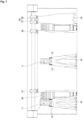
- FIGs. 1 and 2 illustrate the entirety of an automatic cloth feeder 10 to which a buffering device according to the present invention is applied.
- a cloth supply section 11 which is equipped with a clamp 12 holding cloth at a substantially central portion in a movement direction and moving upward toward a feeding conveyor 20 from below is arranged at a position corresponding to a front portion of the feeding conveyor 20.
- the cloth supply section 11 is arranged at three places in total at the center and both ends on the right and left sides on the front face of the feeder main body, and movement mechanisms 13 are respectively provided therein.
- the illustrated movement mechanism 13 includes a belt 13c wound around between upper and lower rollers 13a and 13b which are respectively equipped with a pair of the clamps 12 and 12 on the right and left sides, thereby configuring the cloth supply section 11 in its entirety.
- Each clamp 12 is attached to the belt 13c thereof, and moves upward and downward between a lower position which is closer to a worker so as to be easily attached and a higher position which is higher than a feeding port 20a of the feeding conveyor 20.
- the pair of the clamps 12 and 12 on the right and left sides fixes cloth at the substantially central portion in the movement direction.
- Each clamp 12 may be a known clamp for pinching cloth and moves from the higher position closer to a worker to the higher position closer to the feeding conveyor 20 due to the aforementioned movement configuration (refer to Figs. 2 and 3 ).
- Cloth is attached to the pair of the clamps 12 and 12 on the right and left sides by the worker so as to cause a portion between the pair of the clamps to be as horizontal or linear as possible.
- the movement mechanism 13 does not repeat to move upward and downward in an example of the embodiment described below, but the clamps 12 move from the lower position to the higher position as a part of the movement which circulates a regular route.
- the clamps 12 and the movement mechanism 13 hold cloth at the substantially central portion between the right and left sides in the movement direction and configure the cloth supply section 11 equipped with the clamp 12 which moves upward towards the feeding conveyor 20 from below.
- the cloth supply section 11 configures a cloth standby section 14 in which cloth to be simultaneously carried stands by temporarily.
- the cloth standby section 14 corresponds to the cloth standby section 14 which is arranged at a preceding stage of the feeding conveyor 20.
- a trailing end separation mechanism 15 for cloth is provided so as to be parallel to the cloth supply section 11.
- the trailing end separation mechanism 15 includes a trailing end guidance frame 16 which is formed to have a narrow width at the lower portion and to have a wide width at the upper portion, and a leading end cover 17 provided on a leading end side which is formed to have a narrow width.
- a central portion 17a protrudes outward so as to come into contact with the central portion of cloth to be carried, and the right and left trailing end portions are provided so as to be easily separated to the right and left.
- the reference numeral 18 indicates an operation unit.
- the trailing end separation mechanism 15 helps the trailing end portion of cloth be unerringly separated to the right and left sides even though the below-mentioned feeding conveyor 20 has a short carrying distance.
- the feeding conveyor 20 is arranged at an upper portion of the trailing end separation mechanism 15, and the feeding conveyor 20 is formed with a lower conveyor 19 and an upper conveyor 21.
- the feeding conveyor 20 is arranged so as to be orthogonal to the front face of the feeder main body, and each one is arranged at three places in total behind the cloth supply section 11 ( Figs. 1 and 2 ). Since the feeding conveyor 20 is formed to be short in a cloth movement direction as described before, the trailing end portion of cloth tends to be difficult to separate to the right and left sides compared to a conveyor which is long in the cloth movement direction. In contrast, the trailing end separation mechanism 15 supplements the tendency and contributes to overall miniaturization.
- the lower conveyor 19 is supported upward in its entirety by a pressing mechanism 22 formed with a cylinder device and has a structure in which contact pressure with respect to the upper conveyor 21 is adjustable.
- the feeding conveyor 20 includes the feeding port 20a which is obliquely downward in accordance with a track of the movement mechanism 13 and is provided so as to be able to feed the approaching cloth carried by the clamp 12, with no difficulty.
- the upper conveyor 21 is formed with a belt conveyor and is arranged obliquely upward from below so as to be low on a side closer to the feeding port 20a and high on a side of an output portion on the opposite side ( Fig. 3A ).
- the feeding conveyor 20 which is shaped thin and long in width and length so that cloth to be fed is placed at the substantially central portion and both the right and left portions of the cloth droop.
- crumpling paths 25 and 26 are formed on the right and left sides of the feeding conveyor 20 so as to allow both the right and left portions of cloth drooping from the central portion to both the right and left sides to enter and to be crumpled.
- a pair of sensors 27 and 28 on the right and left sides for checking the arrival of the right and left trailing end portions (Wl and Wr in Fig. 9 ) is arranged at the leading ends of the crumpling paths 25 and 26, and a pair of catch means 29 for catching the trailing end portion is provided farther ahead each on the right and left sides ( Fig. 4 ).
- Each catch means 29 is formed to include a pair of rolls 31 and 32 at the front and rear which is provided to be able to come into contact with and to separate from each other so as to be able to pinch the trailing end portions Wl and Wr of cloth, and a catch member 33 which operates in an arrow direction from an open state to a closed state as illustrated for pinching and holding the right and left trailing end portions of cloth when the right and left trailing end portions approach the place between the pair of the rolls.
- the catch member 33 is open and closed by a drive unit 34 and is provided to be movable in a front and rear direction by a movement mechanism 51 as illustrated in Fig. 5 .
- the movement mechanism 51 is configured to include a slider 52 having an arm for holding the drive unit 34, guide rails 53, and a cylinder of a drive unit 54.
- the movement mechanism 51 is installed on the right and left sides of the feeding conveyor 20.
- the catch means 29 in the embodiment is connected to one end of a crank 35 which is pivotally supported by a support shaft 35a on the feeder main body side, and operates by a drive unit 36 which is connected to the other end of the crank 35 and includes a linear cylinder, for example (refer to Fig. 6 ).
- the catch means 29 including the catch member 33 configures a deposition section 30 for moving cloth to a deposition member 41 while holding the right and left trailing end portions of the cloth together with spreading members 37 and 38 described below.
- the catch member 33 holds the right and left trailing end portions of cloth which is caught by the catch means 29.
- the caught right and left trailing end portions of the cloth are in states of extending upward from below the pair of the rolls 31 and 32, and the catch member 33 holds the lower portion thereof.
- the catch member 33 is provided to be movable in the movement direction of cloth and is provided to correspond to each of the catch means 29.
- a movement range of the catch member 33 is from a reception position R where the right and left trailing end portions of cloth indicated by the solid line in Fig. 6 are received from the catch means 29, to a deposition position S where the right and left trailing end portions are deposited in the pair of the spreading members 37 and 38.
- the spreading members 37 and 38 are provided to form one set with a pair thereof for holding the right and left trailing end portions Wl and Wr of cloth.
- the pair of one set of the spreading members 37 and 38 is provided on both the right and left sides toward the front face of the feeder (refer to Fig. 4 ).
- the right and left trailing end portions of cloth are the trailing end portions when being caught by the catch means 29, but the front and rear positions of cloth W are switched therebetween by being moved over to the spreading members 37 and 38 so as to be spread. Therefore, after being spread, the right and left trailing end portions are carried to the next process as the leading end portions of the cloth W.
- a lifting means 39 is arranged in the deposition position S.
- the lifting means 39 in the embodiment utilizes a suctioning force.
- a picking up method can be applied with no technical problem, for example.
- the lifting means 39 performs suctioning of the right and left trailing end portions of cloth, thereby lifting the right and left trailing end portions of cloth to positions higher than the spreading members 37 and 38.
- the spreading members 37 and 38 move to a standby position in a right and left direction (refer to Fig. 4 ).
- the lifting means 39 temporarily holds the right and left trailing end portions Wl and Wr extending upward from the catch means 29 on account of a suctioning force. In the meantime, the right and left trailing end portions Wl and Wr are held by the spreading members 37 and 38. Therefore, the lifting means 39 is provided in a vertically movable manner in order to take over the right and left trailing end portions.
- the reference numeral 40 denotes a drive unit for vertically moving the lifting means 39, and a known drive device such as the aforementioned linear cylinder is utilized.
- the spreading members 37 and 38 can move in the right and left direction by a guide rail 44 which is installed in an upper portion at the rear portion of the feeder main body.
- the reference numeral 41 in Fig. 6 indicates a movable deposition member, which is provided to be movable in the front and rear direction by a drive mechanism (not illustrated) in order to receive the leading end portions of cloth which are placed on the top face of the catch member 33 at the deposition position S and to hand over the leading end portions to a carrying conveyor 42.
- the spreading members 37 and 38 configure a straightening unit 45 for pulling cloth held in the deposition section 30 to the right and left sides so as to achieve a straightened state.
- the straightening unit 45 is arranged at two places on the right and left sides in the following stage of the feeding conveyor 20, and configures the cloth standby section 14.
- the reference numeral 43 indicates a suctioning box which performs suctioning of fed cloth and straightens the cloth so as to be in its original shape.
- the lifting means 39 moves downward, approaches the right and left trailing end portions Wl and Wr of the cloth W, and performs suctioning of the right and left trailing end portions Wl and Wr, thereby lifting the right and left trailing end portions Wl and Wr to positions higher than the spreading members 37 and 38.
- the spreading members 37 and 38 approach the right and left trailing end portions Wl and Wr of cloth at a position higher than the catch member 33 which is at the deposition position S, thereby holding the right and left trailing end portions Wl and Wr.
- the first stage of transferring the cloth W is completed (refer to Fig. 9A ).
- the trailing end portions Wl and Wr of cloth may be referred to as the leading end portions of the cloth switched thereafter.
- the spreading members 37 and 38 holding the right and left trailing end portions Wl and Wr of the cloth W spread the cloth to the right and left sides while moving to the central portion of the feeder main body.
- a supplying amount of cloth depends on only the working speed of a worker, and thus, it is not possible that the working speed exceeds the feeding speed of the automatic feeder.
- one piece of the cloth W is fed into the process in accordance with the above-described feeding processing at one place among the three places of the clamps 12 and the cloth W is not directly placed on the feeding conveyor, but the cloth passes through the movement mechanism 13 first. Accordingly, the movement mechanism 13 functions as the cloth standby section 14 at the preceding stage of the feeding conveyor 20.
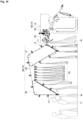
- Fig. 9 illustrates a state where the right and left trailing end portions Wl and Wr of cloth W are held by the catch means 29 and the like.
- Fig. 9A illustrates a state passing through three processes such as a process in which the cloth W is held by the clamp 12 in the device of the present invention, a process in which detection of the right and left trailing end portions is performed while being carried in the feeding conveyor 20, and a process in which the right and left trailing end portions are held by the catch means 29.
- Fig. 9B illustrates the buffering state in the device of the present invention in which a process of spreading cloth performed by the straightening unit 45 formed with the spreading members 37 and 38 is added to that in Fig. 9A .
- a straightening process performed by the straightening unit 45 is added, the number of processes that the cloth must pass through is double that of the processes in the related art, when simply comparing the numbers of processes therebetween.
- a pair of the straightening unit 45 is arranged on the right and left sides with respect to the deposition section 30 at one place, it is found out that a temporary standby time or timing for cloth can be gained further.
- the cloth standby section 14 includes a circulation carrying device 50 together with a dedicated portion 49 for buffering and is provided with multiple clamps 12 which move along a circulation route so as to cause the cloth W to be held at the substantially central portion between the right and left sides in the movement direction.
- the circulation carrying device 50 includes a plurality of circulation conveyors 46 and 47, and a conveyor belt 48 is wound around therebetween. The multiple clamps 12 are attached to the conveyor belt 48.
- a worker P can concentrate on only attaching the cloth W to the clamp 12 in the circulation carrying device 50, and the attaching is performed independently of an operation of an automatic feeder 10.
- the last conveyor line in the circulation carrying device 50 coincides with the conveyor in the movement mechanism 13 as illustrated in Fig. 2 and the like, and the content in the dedicated portion 49 for buffering between the circulation conveyors 46 and 47 can be arbitrarily set, thereby leading to the rapidly improved standby performance of the movement mechanism 13.
Landscapes
- Engineering & Computer Science (AREA)
- Textile Engineering (AREA)
- Treatment Of Fiber Materials (AREA)
- Harvester Elements (AREA)
Claims (3)
- Alimenteur automatique de tissu (10) comprenant :un convoyeur d'alimentation (20) conçu pour transporter un tissu (W) dans une direction de transport jusqu'à une section de dépôt (30) et pour plisser le tissu (W) depuis les côtés droit et gauche ;des éléments de guidage (23, 24) présentant des formes coniques et agencés sur des côtés droit et gauche du convoyeur d'alimentation (20) et formant des voies de plissage (25, 26) sur les côtés droit et gauche du convoyeur d'alimentation (20) de façon à permettre à des parties droite et gauche du tissu (W) s'affaissant depuis une partie centrale vers les côtés droit et gauche d'entrer et d'être rassemblées et plissées ;une paire de capteurs (27, 28) agencés sur le côté gauche et droit du convoyeur d'alimentation (20) à des extrémités avant des voies de plissage (25, 26) et qui sont conçus pour détecter l'arrivée de parties d'extrémité arrière droite et gauche (Wr, WI) du tissu (W) transporté par le convoyeur d'alimentation (20) ;la section de dépôt (30) comprenant une paire de moyens de saisie (29) situés plus en avant sur les côtés droit et gauche et qui sont conçus pour saisir et maintenir les parties d'extrémité arrière droite et gauche (Wr, WI) du tissu (W) détectées par les capteurs (27, 28) et pour alimenter le tissu (W) avec les parties d'extrémité arrière droite et gauche (Wr, WI) en tant que parties d'extrémité avant dans un processus ; etun dispositif d'amortissement comprenant une section d'acheminement de tissu (11) située à une étape précédente par rapport au convoyeur d'alimentation (20) et conçue pour se déplacer vers le haut en direction du convoyeur d'alimentation (20) pour introduire le tissu (W) par le dessous dans le convoyeur d'alimentation (20) sur une partie sensiblement centrale du tissu (W) dans la direction de transport,dans lequel la section d'acheminement de tissu (11) est agencée en une position correspondant à une partie avant du convoyeur d'alimentation (20), et équipée d'une pince (12) qui est conçue pour maintenir le tissu (W) sur une partie sensiblement centrale entre les côtés droit et gauche du tissu (W), de telle sorte que la section d'acheminement de tissu (11) est conçue pour approvisionner une section d'attente de tissu (14) dans laquelle le tissu (W) transporté est temporairement en attente de façon à accumuler et acheminer une quantité de tissu (W) dépassant une quantité de traitement d'alimentation et à poursuivre l'alimentation dans le convoyeur d'alimentation (20) sans encombrement dans l'alimenteur automatique de tissu (10).
- Alimenteur automatique de tissu (10) selon la revendication 1,
comprenant en outre un dispositif de transport de circulation (50) équipé de plusieurs pinces (12) conçues pour maintenir le tissu (W) le long d'un trajet de circulation du dispositif de transport de circulation (50), et conçu pour fixer le tissu (W) aux pinces (12) sur la partie sensiblement centrale entre les côtés droit et gauche dans la direction de transport, le dispositif de transport de circulation (50) comprenant une partie dédiée (49) à l'amortissement de façon à constituer une autre section d'attente de tissu (14). - Alimenteur automatique de tissu (10) selon la revendication 1,
comprenant en outre une pluralité d'unités de redressage (45) situées à l'étape suivante par rapport au convoyeur d'alimentation (20), les unités de redressage (45) étant conçues pour amener le tissu (W) maintenu dans la section de dépôt à se trouver dans un état redressé en tirant le tissu (W) vers les côtés droit et gauche, et les unités de redressage (45) étant agencées en une pluralité d'emplacements de façon à constituer une autre section d'attente de tissu (14).
Applications Claiming Priority (2)
| Application Number | Priority Date | Filing Date | Title |
|---|---|---|---|
| JP2014237821A JP6553349B2 (ja) | 2014-11-25 | 2014-11-25 | 布類自動投入機におけるバッファリング装置 |
| PCT/JP2015/061842 WO2016084401A1 (fr) | 2014-11-25 | 2015-04-17 | Dispositif d'amortissement pour un dispositif de chargement d'article en tissu automatisé |
Publications (3)
| Publication Number | Publication Date |
|---|---|
| EP3225732A1 EP3225732A1 (fr) | 2017-10-04 |
| EP3225732A4 EP3225732A4 (fr) | 2018-06-27 |
| EP3225732B1 true EP3225732B1 (fr) | 2025-01-22 |
Family
ID=56073986
Family Applications (1)
| Application Number | Title | Priority Date | Filing Date |
|---|---|---|---|
| EP15862854.5A Active EP3225732B1 (fr) | 2014-11-25 | 2015-04-17 | Dispositif d'amortissement pour un dispositif de chargement d'article en tissu automatisé |
Country Status (8)
| Country | Link |
|---|---|
| US (1) | US10246814B2 (fr) |
| EP (1) | EP3225732B1 (fr) |
| JP (1) | JP6553349B2 (fr) |
| CN (1) | CN107002344B (fr) |
| CA (1) | CA2966475C (fr) |
| DK (1) | DK3225732T3 (fr) |
| TW (1) | TWI577853B (fr) |
| WO (1) | WO2016084401A1 (fr) |
Families Citing this family (8)
| Publication number | Priority date | Publication date | Assignee | Title |
|---|---|---|---|---|
| EP4568242A1 (fr) | 2016-05-13 | 2025-06-11 | Sony Group Corporation | Dispositif et procédé de traitement d'image |
| JP7064841B2 (ja) * | 2017-09-27 | 2022-05-11 | 株式会社プレックス | 布類展開装置 |
| JP7219025B2 (ja) * | 2018-07-05 | 2023-02-07 | 株式会社プレックス | 布類搬送装置 |
| WO2021239368A1 (fr) * | 2020-05-25 | 2021-12-02 | Jensen Denmark A/S | Appareil permettant d'étendre du linge |
| WO2022113240A1 (fr) * | 2020-11-26 | 2022-06-02 | 東都フォルダー工業株式会社 | Dispositif de dépliage de tissu pour déplier un tissu, dispositif de chargement de tissu pour transporter ledit tissu déplié vers l'étape suivante |
| JP7811017B2 (ja) * | 2020-12-17 | 2026-02-04 | 東都フォルダー工業株式会社 | 投入ユニットと、中間装置を有する布類投入装置 |
| JP7784153B2 (ja) * | 2021-02-26 | 2025-12-11 | 東都フォルダー工業株式会社 | 布類投入装置と、その布類投入装置を有する布類展開装置 |
| WO2025219408A1 (fr) * | 2024-04-19 | 2025-10-23 | Jensen Denmark A/S | Dispositifs et procédés de transport d'articles de linge |
Family Cites Families (31)
| Publication number | Priority date | Publication date | Assignee | Title |
|---|---|---|---|---|
| NL295100A (fr) * | 1962-07-09 | |||
| GB1061912A (en) * | 1964-04-15 | 1967-03-15 | Ilford Laundry Ltd | Calenders or like apparatus |
| US3911604A (en) * | 1975-01-20 | 1975-10-14 | Sjostrom Kathleen Alice | Fabric spreading and feeding machine |
| US4327510A (en) * | 1980-07-28 | 1982-05-04 | Grantham Frederick W | Multi-station laundry feeder |
| DE3119574C2 (de) * | 1981-05-16 | 1983-11-10 | Herbert Kannegiesser Gmbh + Co, 4973 Vlotho | Vorrichtung zum Zuführen von Wäschestücken zu einer Mangel |
| JPH0722640B2 (ja) * | 1986-03-13 | 1995-03-15 | 三菱重工業株式会社 | 布片の展開方法とその展開装置 |
| EP0272368B1 (fr) * | 1986-12-01 | 1991-08-21 | Mitsubishi Jukogyo Kabushiki Kaisha | Méthode et appareil pour saisir les coins d'une pièce de linge |
| DE3839045A1 (de) * | 1988-06-04 | 1989-12-07 | Kannegiesser H Gmbh Co | Verfahren und vorrichtung zum zufuehren von waeschestuecken zu einer mangel |
| JP2659776B2 (ja) * | 1988-12-02 | 1997-09-30 | 三菱重工業株式会社 | 布片の展開方法 |
| DE68925787T2 (de) * | 1988-12-02 | 1996-07-11 | Mitsubishi Heavy Ind Ltd | Verfahren und Vorrichtung zum Ausbreiten von Gewebestücken |
| JP2695661B2 (ja) * | 1989-06-16 | 1998-01-14 | 三菱重工業株式会社 | 布片の展開方法及び装置 |
| DE3912977C2 (de) * | 1989-04-20 | 2001-04-19 | Kannegiesser H Gmbh Co | Verfahren und Vorrichtung zum Zuführen von Wäschestücken zu einer Mangel |
| JPH0418400A (ja) * | 1990-02-02 | 1992-01-22 | Kanebo Ltd | 不正乗車防止用定期券 |
| JPH04158899A (ja) * | 1990-10-23 | 1992-06-01 | Tokyo Sensen Kikai Seisakusho:Kk | 洗濯物の仕上前処理装置 |
| US5440810A (en) * | 1994-03-16 | 1995-08-15 | Chicago Dryer Company | Apparatus for feeding and spreading laundry articles |
| DK171332B1 (da) * | 1994-04-28 | 1996-09-09 | Jensen Ejnar & Soen As | Indretning til indfødning af tøjstykker i en ilægger |
| US5515627A (en) * | 1994-07-27 | 1996-05-14 | Mccabe; Stanley G. | Apparatus and method for feeding flatwork articles |
| DK0751251T3 (da) * | 1995-01-10 | 2002-08-19 | Tokai Co Ltd | Fremgangsmåde og apparat til automatisk slutbehandling af firkantede klædestykker |
| JPH10550A (ja) | 1996-06-11 | 1998-01-06 | Toshiba Mach Co Ltd | 研磨布ドレッシング方法およびその装置 |
| JPH11114296A (ja) * | 1997-10-20 | 1999-04-27 | Tokai:Kk | 展開すべき布類の前処理装置 |
| JP4179828B2 (ja) * | 2002-08-30 | 2008-11-12 | 洋左右 前嶋 | 布製品の展開方法 |
| JP4043345B2 (ja) * | 2002-11-14 | 2008-02-06 | 株式会社プレックス | 布類展張方法及び布類展張機 |
| JP2007092255A (ja) * | 2005-09-30 | 2007-04-12 | Purex:Kk | 布類展張方法および布類展張機 |
| DK176608B1 (da) * | 2007-05-23 | 2008-11-10 | Jensen Denmark As | Fremgangsmåde ved drift af spredeklemmer |
| DE102007040465B3 (de) * | 2007-06-20 | 2009-02-26 | Herbert Kannegiesser Gmbh | Vorrichtung zum Zuführen von Wäschestücken zu einer Wäschebehandlungseinrichtung, insbesondere einer Mangel |
| JP4800370B2 (ja) * | 2008-11-10 | 2011-10-26 | 洋左右 前嶋 | 布類投入機における布類の受け渡し装置 |
| JP5581019B2 (ja) * | 2009-07-31 | 2014-08-27 | 株式会社プレックス | 方形状布類展開装置 |
| JP5419588B2 (ja) * | 2009-08-07 | 2014-02-19 | 株式会社プレックス | 方形状布類展開装置 |
| DE102009058637A1 (de) * | 2009-12-16 | 2011-06-22 | Herbert Kannegiesser GmbH, 32602 | Verfahren und Vorrichtung zum Zuführen eines Wäschestücks zu einer Mangel oder dergleichen |
| ES2539424T3 (es) * | 2011-10-17 | 2015-06-30 | Girbau Robotics | Máquina para extender y cargar artículos de ropa plana |
| CN103998678B (zh) * | 2011-10-17 | 2016-11-02 | 高达机器人公司 | 用于铺展和装载平状衣物制品的机器 |
-
2014
- 2014-11-25 JP JP2014237821A patent/JP6553349B2/ja active Active
-
2015
- 2015-04-17 US US15/525,619 patent/US10246814B2/en active Active
- 2015-04-17 CN CN201580057908.9A patent/CN107002344B/zh active Active
- 2015-04-17 CA CA2966475A patent/CA2966475C/fr active Active
- 2015-04-17 EP EP15862854.5A patent/EP3225732B1/fr active Active
- 2015-04-17 DK DK15862854.5T patent/DK3225732T3/da active
- 2015-04-17 WO PCT/JP2015/061842 patent/WO2016084401A1/fr not_active Ceased
- 2015-05-22 TW TW104116356A patent/TWI577853B/zh not_active IP Right Cessation
Also Published As
| Publication number | Publication date |
|---|---|
| JP2016097170A (ja) | 2016-05-30 |
| WO2016084401A1 (fr) | 2016-06-02 |
| TW201619468A (zh) | 2016-06-01 |
| US20170335505A1 (en) | 2017-11-23 |
| DK3225732T3 (da) | 2025-03-31 |
| CN107002344A (zh) | 2017-08-01 |
| US10246814B2 (en) | 2019-04-02 |
| EP3225732A4 (fr) | 2018-06-27 |
| CA2966475C (fr) | 2020-01-14 |
| JP6553349B2 (ja) | 2019-07-31 |
| CN107002344B (zh) | 2019-07-30 |
| EP3225732A1 (fr) | 2017-10-04 |
| TWI577853B (zh) | 2017-04-11 |
| CA2966475A1 (fr) | 2016-06-02 |
Similar Documents
| Publication | Publication Date | Title |
|---|---|---|
| EP3225732B1 (fr) | Dispositif d'amortissement pour un dispositif de chargement d'article en tissu automatisé | |
| JP7275229B2 (ja) | 布片を送給し広げるための装置 | |
| US11339526B2 (en) | Method for feeding pieces of laundry to a laundry subsequent handling apparatus and device | |
| EP3305977B1 (fr) | Dispositif de chargement de textile automatisé | |
| EP3636825B1 (fr) | Procédé et dispositif servant à acheminer des pièces de linge jusqu'à un dispositif de traitement de pièces de linge, en particulier une calandre | |
| HUP0203861A2 (en) | Device for transporting a flat section of a product | |
| RU2626943C2 (ru) | Способ и устройство для транспортировки плоских изделий | |
| JPH01209002A (ja) | 生地付きスライドファスナーチェーンの整列方法とその装置 | |
| US20250257521A1 (en) | A device for capturing a cloth item, and a method of operating the device | |
| HK1243469B (zh) | 自动布草装料机 |
Legal Events
| Date | Code | Title | Description |
|---|---|---|---|
| STAA | Information on the status of an ep patent application or granted ep patent |
Free format text: STATUS: THE INTERNATIONAL PUBLICATION HAS BEEN MADE |
|
| PUAI | Public reference made under article 153(3) epc to a published international application that has entered the european phase |
Free format text: ORIGINAL CODE: 0009012 |
|
| STAA | Information on the status of an ep patent application or granted ep patent |
Free format text: STATUS: REQUEST FOR EXAMINATION WAS MADE |
|
| 17P | Request for examination filed |
Effective date: 20170426 |
|
| AK | Designated contracting states |
Kind code of ref document: A1 Designated state(s): AL AT BE BG CH CY CZ DE DK EE ES FI FR GB GR HR HU IE IS IT LI LT LU LV MC MK MT NL NO PL PT RO RS SE SI SK SM TR |
|
| AX | Request for extension of the european patent |
Extension state: BA ME |
|
| DAV | Request for validation of the european patent (deleted) | ||
| DAX | Request for extension of the european patent (deleted) | ||
| A4 | Supplementary search report drawn up and despatched |
Effective date: 20180530 |
|
| RIC1 | Information provided on ipc code assigned before grant |
Ipc: D06F 67/04 20060101AFI20180524BHEP |
|
| STAA | Information on the status of an ep patent application or granted ep patent |
Free format text: STATUS: EXAMINATION IS IN PROGRESS |
|
| 17Q | First examination report despatched |
Effective date: 20200224 |
|
| GRAP | Despatch of communication of intention to grant a patent |
Free format text: ORIGINAL CODE: EPIDOSNIGR1 |
|
| STAA | Information on the status of an ep patent application or granted ep patent |
Free format text: STATUS: GRANT OF PATENT IS INTENDED |
|
| INTG | Intention to grant announced |
Effective date: 20240910 |
|
| GRAS | Grant fee paid |
Free format text: ORIGINAL CODE: EPIDOSNIGR3 |
|
| GRAA | (expected) grant |
Free format text: ORIGINAL CODE: 0009210 |
|
| STAA | Information on the status of an ep patent application or granted ep patent |
Free format text: STATUS: THE PATENT HAS BEEN GRANTED |
|
| AK | Designated contracting states |
Kind code of ref document: B1 Designated state(s): AL AT BE BG CH CY CZ DE DK EE ES FI FR GB GR HR HU IE IS IT LI LT LU LV MC MK MT NL NO PL PT RO RS SE SI SK SM TR |
|
| REG | Reference to a national code |
Ref country code: GB Ref legal event code: FG4D |
|
| REG | Reference to a national code |
Ref country code: CH Ref legal event code: EP |
|
| REG | Reference to a national code |
Ref country code: IE Ref legal event code: FG4D |
|
| REG | Reference to a national code |
Ref country code: DE Ref legal event code: R096 Ref document number: 602015090912 Country of ref document: DE |
|
| P01 | Opt-out of the competence of the unified patent court (upc) registered |
Free format text: CASE NUMBER: APP_5457/2025 Effective date: 20250131 |
|
| REG | Reference to a national code |
Ref country code: DK Ref legal event code: T3 Effective date: 20250326 |
|
| PGFP | Annual fee paid to national office [announced via postgrant information from national office to epo] |
Ref country code: DK Payment date: 20250325 Year of fee payment: 11 |
|
| REG | Reference to a national code |
Ref country code: NL Ref legal event code: MP Effective date: 20250122 |
|
| PG25 | Lapsed in a contracting state [announced via postgrant information from national office to epo] |
Ref country code: NL Free format text: LAPSE BECAUSE OF FAILURE TO SUBMIT A TRANSLATION OF THE DESCRIPTION OR TO PAY THE FEE WITHIN THE PRESCRIBED TIME-LIMIT Effective date: 20250122 |
|
| PG25 | Lapsed in a contracting state [announced via postgrant information from national office to epo] |
Ref country code: RS Free format text: LAPSE BECAUSE OF FAILURE TO SUBMIT A TRANSLATION OF THE DESCRIPTION OR TO PAY THE FEE WITHIN THE PRESCRIBED TIME-LIMIT Effective date: 20250422 |
|
| PG25 | Lapsed in a contracting state [announced via postgrant information from national office to epo] |
Ref country code: FI Free format text: LAPSE BECAUSE OF FAILURE TO SUBMIT A TRANSLATION OF THE DESCRIPTION OR TO PAY THE FEE WITHIN THE PRESCRIBED TIME-LIMIT Effective date: 20250122 |
|
| PG25 | Lapsed in a contracting state [announced via postgrant information from national office to epo] |
Ref country code: PL Free format text: LAPSE BECAUSE OF FAILURE TO SUBMIT A TRANSLATION OF THE DESCRIPTION OR TO PAY THE FEE WITHIN THE PRESCRIBED TIME-LIMIT Effective date: 20250122 |
|
| PGFP | Annual fee paid to national office [announced via postgrant information from national office to epo] |
Ref country code: DE Payment date: 20250305 Year of fee payment: 11 |
|
| PG25 | Lapsed in a contracting state [announced via postgrant information from national office to epo] |
Ref country code: ES Free format text: LAPSE BECAUSE OF FAILURE TO SUBMIT A TRANSLATION OF THE DESCRIPTION OR TO PAY THE FEE WITHIN THE PRESCRIBED TIME-LIMIT Effective date: 20250122 |
|
| REG | Reference to a national code |
Ref country code: LT Ref legal event code: MG9D |
|
| PG25 | Lapsed in a contracting state [announced via postgrant information from national office to epo] |
Ref country code: IS Free format text: LAPSE BECAUSE OF FAILURE TO SUBMIT A TRANSLATION OF THE DESCRIPTION OR TO PAY THE FEE WITHIN THE PRESCRIBED TIME-LIMIT Effective date: 20250522 Ref country code: NO Free format text: LAPSE BECAUSE OF FAILURE TO SUBMIT A TRANSLATION OF THE DESCRIPTION OR TO PAY THE FEE WITHIN THE PRESCRIBED TIME-LIMIT Effective date: 20250422 |
|
| REG | Reference to a national code |
Ref country code: AT Ref legal event code: MK05 Ref document number: 1761547 Country of ref document: AT Kind code of ref document: T Effective date: 20250122 |
|
| PG25 | Lapsed in a contracting state [announced via postgrant information from national office to epo] |
Ref country code: HR Free format text: LAPSE BECAUSE OF FAILURE TO SUBMIT A TRANSLATION OF THE DESCRIPTION OR TO PAY THE FEE WITHIN THE PRESCRIBED TIME-LIMIT Effective date: 20250122 |
|
| PG25 | Lapsed in a contracting state [announced via postgrant information from national office to epo] |
Ref country code: LV Free format text: LAPSE BECAUSE OF FAILURE TO SUBMIT A TRANSLATION OF THE DESCRIPTION OR TO PAY THE FEE WITHIN THE PRESCRIBED TIME-LIMIT Effective date: 20250122 Ref country code: PT Free format text: LAPSE BECAUSE OF FAILURE TO SUBMIT A TRANSLATION OF THE DESCRIPTION OR TO PAY THE FEE WITHIN THE PRESCRIBED TIME-LIMIT Effective date: 20250522 |
|
| PG25 | Lapsed in a contracting state [announced via postgrant information from national office to epo] |
Ref country code: GR Free format text: LAPSE BECAUSE OF FAILURE TO SUBMIT A TRANSLATION OF THE DESCRIPTION OR TO PAY THE FEE WITHIN THE PRESCRIBED TIME-LIMIT Effective date: 20250423 Ref country code: BG Free format text: LAPSE BECAUSE OF FAILURE TO SUBMIT A TRANSLATION OF THE DESCRIPTION OR TO PAY THE FEE WITHIN THE PRESCRIBED TIME-LIMIT Effective date: 20250122 |
|
| PG25 | Lapsed in a contracting state [announced via postgrant information from national office to epo] |
Ref country code: AT Free format text: LAPSE BECAUSE OF FAILURE TO SUBMIT A TRANSLATION OF THE DESCRIPTION OR TO PAY THE FEE WITHIN THE PRESCRIBED TIME-LIMIT Effective date: 20250122 |
|
| PG25 | Lapsed in a contracting state [announced via postgrant information from national office to epo] |
Ref country code: SE Free format text: LAPSE BECAUSE OF FAILURE TO SUBMIT A TRANSLATION OF THE DESCRIPTION OR TO PAY THE FEE WITHIN THE PRESCRIBED TIME-LIMIT Effective date: 20250122 |
|
| PG25 | Lapsed in a contracting state [announced via postgrant information from national office to epo] |
Ref country code: SM Free format text: LAPSE BECAUSE OF FAILURE TO SUBMIT A TRANSLATION OF THE DESCRIPTION OR TO PAY THE FEE WITHIN THE PRESCRIBED TIME-LIMIT Effective date: 20250122 |
|
| PG25 | Lapsed in a contracting state [announced via postgrant information from national office to epo] |
Ref country code: IT Free format text: LAPSE BECAUSE OF FAILURE TO SUBMIT A TRANSLATION OF THE DESCRIPTION OR TO PAY THE FEE WITHIN THE PRESCRIBED TIME-LIMIT Effective date: 20250122 |
|
| PG25 | Lapsed in a contracting state [announced via postgrant information from national office to epo] |
Ref country code: EE Free format text: LAPSE BECAUSE OF FAILURE TO SUBMIT A TRANSLATION OF THE DESCRIPTION OR TO PAY THE FEE WITHIN THE PRESCRIBED TIME-LIMIT Effective date: 20250122 Ref country code: CZ Free format text: LAPSE BECAUSE OF FAILURE TO SUBMIT A TRANSLATION OF THE DESCRIPTION OR TO PAY THE FEE WITHIN THE PRESCRIBED TIME-LIMIT Effective date: 20250122 |
|
| REG | Reference to a national code |
Ref country code: DE Ref legal event code: R097 Ref document number: 602015090912 Country of ref document: DE |
|
| PG25 | Lapsed in a contracting state [announced via postgrant information from national office to epo] |
Ref country code: RO Free format text: LAPSE BECAUSE OF FAILURE TO SUBMIT A TRANSLATION OF THE DESCRIPTION OR TO PAY THE FEE WITHIN THE PRESCRIBED TIME-LIMIT Effective date: 20250122 |
|
| PG25 | Lapsed in a contracting state [announced via postgrant information from national office to epo] |
Ref country code: SK Free format text: LAPSE BECAUSE OF FAILURE TO SUBMIT A TRANSLATION OF THE DESCRIPTION OR TO PAY THE FEE WITHIN THE PRESCRIBED TIME-LIMIT Effective date: 20250122 |
|
| REG | Reference to a national code |
Ref country code: CH Ref legal event code: H13 Free format text: ST27 STATUS EVENT CODE: U-0-0-H10-H13 (AS PROVIDED BY THE NATIONAL OFFICE) Effective date: 20251125 |
|
| PLBE | No opposition filed within time limit |
Free format text: ORIGINAL CODE: 0009261 |
|
| STAA | Information on the status of an ep patent application or granted ep patent |
Free format text: STATUS: NO OPPOSITION FILED WITHIN TIME LIMIT |
|
| PG25 | Lapsed in a contracting state [announced via postgrant information from national office to epo] |
Ref country code: LU Free format text: LAPSE BECAUSE OF NON-PAYMENT OF DUE FEES Effective date: 20250417 |
|
| PG25 | Lapsed in a contracting state [announced via postgrant information from national office to epo] |
Ref country code: MC Free format text: LAPSE BECAUSE OF FAILURE TO SUBMIT A TRANSLATION OF THE DESCRIPTION OR TO PAY THE FEE WITHIN THE PRESCRIBED TIME-LIMIT Effective date: 20250122 |
|
| GBPC | Gb: european patent ceased through non-payment of renewal fee |
Effective date: 20250422 |
|
| REG | Reference to a national code |
Ref country code: BE Ref legal event code: MM Effective date: 20250430 |
|
| 26N | No opposition filed |
Effective date: 20251023 |
|
| PG25 | Lapsed in a contracting state [announced via postgrant information from national office to epo] |
Ref country code: GB Free format text: LAPSE BECAUSE OF NON-PAYMENT OF DUE FEES Effective date: 20250422 |
|
| PG25 | Lapsed in a contracting state [announced via postgrant information from national office to epo] |
Ref country code: FR Free format text: LAPSE BECAUSE OF NON-PAYMENT OF DUE FEES Effective date: 20250430 |
|
| PG25 | Lapsed in a contracting state [announced via postgrant information from national office to epo] |
Ref country code: BE Free format text: LAPSE BECAUSE OF NON-PAYMENT OF DUE FEES Effective date: 20250430 |
|
| PG25 | Lapsed in a contracting state [announced via postgrant information from national office to epo] |
Ref country code: CH Free format text: LAPSE BECAUSE OF NON-PAYMENT OF DUE FEES Effective date: 20250430 |
|
| PG25 | Lapsed in a contracting state [announced via postgrant information from national office to epo] |
Ref country code: IE Free format text: LAPSE BECAUSE OF NON-PAYMENT OF DUE FEES Effective date: 20250417 |