EP3230403B1 - Organische verbindungen mit löslichen gruppen - Google Patents
Organische verbindungen mit löslichen gruppen Download PDFInfo
- Publication number
- EP3230403B1 EP3230403B1 EP15805389.2A EP15805389A EP3230403B1 EP 3230403 B1 EP3230403 B1 EP 3230403B1 EP 15805389 A EP15805389 A EP 15805389A EP 3230403 B1 EP3230403 B1 EP 3230403B1
- Authority
- EP
- European Patent Office
- Prior art keywords
- group
- organic
- carbon atoms
- groups
- substituted
- Prior art date
- Legal status (The legal status is an assumption and is not a legal conclusion. Google has not performed a legal analysis and makes no representation as to the accuracy of the status listed.)
- Active
Links
- 0 CC1C=C*C1 Chemical compound CC1C=C*C1 0.000 description 6
- SYAXTNNPVLERFI-CLFYSBASSA-N CC/C(/C)=C\C(C)NC(C)C Chemical compound CC/C(/C)=C\C(C)NC(C)C SYAXTNNPVLERFI-CLFYSBASSA-N 0.000 description 1
- VQMPTVQCADWACQ-UHFFFAOYSA-N CCC(C)(CC)N Chemical compound CCC(C)(CC)N VQMPTVQCADWACQ-UHFFFAOYSA-N 0.000 description 1
- YTRHWXRSCMFXFG-UHFFFAOYSA-N CCCCCCCCOc1cc(N2c3ccccc3C3(c4cc(Br)ccc4-c(cc4)c3cc4Br)c3ccccc23)cc(OCCCCCCCC)c1 Chemical compound CCCCCCCCOc1cc(N2c3ccccc3C3(c4cc(Br)ccc4-c(cc4)c3cc4Br)c3ccccc23)cc(OCCCCCCCC)c1 YTRHWXRSCMFXFG-UHFFFAOYSA-N 0.000 description 1
- VWWMUJVMSPERFB-UHFFFAOYSA-N CCCCCCc(cc1c2c3ccc(CCCCCC)c2)ccc1[n]3-c(c(C#N)c(c(C#N)c1-[n]2c(ccc(CCCCCC)c3)c3c3cc(CCCCCC)ccc23)-[n]2c3ccc(CCCCCC)cc3c3c2ccc(CCCCCC)c3)c1C#N Chemical compound CCCCCCc(cc1c2c3ccc(CCCCCC)c2)ccc1[n]3-c(c(C#N)c(c(C#N)c1-[n]2c(ccc(CCCCCC)c3)c3c3cc(CCCCCC)ccc23)-[n]2c3ccc(CCCCCC)cc3c3c2ccc(CCCCCC)c3)c1C#N VWWMUJVMSPERFB-UHFFFAOYSA-N 0.000 description 1
- VVDXEUDRHRVHKG-OCAPTIKFSA-N CCO[C@H](CC1)CC[C@H]1N Chemical compound CCO[C@H](CC1)CC[C@H]1N VVDXEUDRHRVHKG-OCAPTIKFSA-N 0.000 description 1
- VBISYHUPKMUNDH-UHFFFAOYSA-N COCCOCCOc(cc1C2(c3c4)c(cc(cc5)C#N)c5-c(cc5)c2cc5C#N)ccc1-c3ccc4-c(cc1)ccc1N(c1ccccc1)c1ccccc1 Chemical compound COCCOCCOc(cc1C2(c3c4)c(cc(cc5)C#N)c5-c(cc5)c2cc5C#N)ccc1-c3ccc4-c(cc1)ccc1N(c1ccccc1)c1ccccc1 VBISYHUPKMUNDH-UHFFFAOYSA-N 0.000 description 1
- LWECGSHDDRBZRA-UHFFFAOYSA-N COCCOc(cc1)ccc1N(c(cc1)ccc1OCCO)c(cc1)cc(C23c4cc(C#N)ccc4-c(cc4)c2cc4C#N)c1-c(cc1)c3cc1N(c(cc1)ccc1OCCOC)c(cc1)ccc1OCCOC Chemical compound COCCOc(cc1)ccc1N(c(cc1)ccc1OCCO)c(cc1)cc(C23c4cc(C#N)ccc4-c(cc4)c2cc4C#N)c1-c(cc1)c3cc1N(c(cc1)ccc1OCCOC)c(cc1)ccc1OCCOC LWECGSHDDRBZRA-UHFFFAOYSA-N 0.000 description 1
- CKNVSFHTAJBYOD-UHFFFAOYSA-N Cc1cccc2c1OCCO2 Chemical compound Cc1cccc2c1OCCO2 CKNVSFHTAJBYOD-UHFFFAOYSA-N 0.000 description 1
- JMKMMSYPKFUFQY-UHFFFAOYSA-N N#CC(C#N)=C(c1ccccc11)c2ccccc2C11c2ccccc2N(c2cc(-c3cccc(-c4ccccc4)c3)cc(-c3cc(-c4ccccc4)ccc3)c2)c2ccccc12 Chemical compound N#CC(C#N)=C(c1ccccc11)c2ccccc2C11c2ccccc2N(c2cc(-c3cccc(-c4ccccc4)c3)cc(-c3cc(-c4ccccc4)ccc3)c2)c2ccccc12 JMKMMSYPKFUFQY-UHFFFAOYSA-N 0.000 description 1
- RSIXESAWODCSQB-UHFFFAOYSA-N N#CC(C#N)=C(c1ccccc11)c2ccccc2C11c2ccccc2N(c2cc(-c3ccccc3)cc(-c3ccccc3)c2)c2c1cccc2 Chemical compound N#CC(C#N)=C(c1ccccc11)c2ccccc2C11c2ccccc2N(c2cc(-c3ccccc3)cc(-c3ccccc3)c2)c2c1cccc2 RSIXESAWODCSQB-UHFFFAOYSA-N 0.000 description 1
- QDJOGIDHYNTWNM-UHFFFAOYSA-N N#Cc(cc1C#N)cc(C#N)c1F Chemical compound N#Cc(cc1C#N)cc(C#N)c1F QDJOGIDHYNTWNM-UHFFFAOYSA-N 0.000 description 1
- LQZWMJJKWKMJPY-UHFFFAOYSA-N N#Cc(cc1C2(c3c4)c(cc(cc5)N(c6cc(-c7ccccc7)ccc6)c(c(-c6ccccc6)ccc6)c6-c6ccccc6)c5-c5ccccc25)ccc1-c3ccc4C#N Chemical compound N#Cc(cc1C2(c3c4)c(cc(cc5)N(c6cc(-c7ccccc7)ccc6)c(c(-c6ccccc6)ccc6)c6-c6ccccc6)c5-c5ccccc25)ccc1-c3ccc4C#N LQZWMJJKWKMJPY-UHFFFAOYSA-N 0.000 description 1
- PXTSQKCCMVGZET-MCTFVDOGSA-N Nc(cc1C2(C(/C=C\C=C/CC(C=C3)=C4)=CC=C2/C=C\C34O)c2c3)ccc1-c2ccc3P Chemical compound Nc(cc1C2(C(/C=C\C=C/CC(C=C3)=C4)=CC=C2/C=C\C34O)c2c3)ccc1-c2ccc3P PXTSQKCCMVGZET-MCTFVDOGSA-N 0.000 description 1
- ISASPHPUWOPDJS-UHFFFAOYSA-N Nc1c2-c3ccccc3C(C3C=CC=CC33)(c4c3cccc4)c2ccc1 Chemical compound Nc1c2-c3ccccc3C(C3C=CC=CC33)(c4c3cccc4)c2ccc1 ISASPHPUWOPDJS-UHFFFAOYSA-N 0.000 description 1
- PMJINXYVWUMEEV-UHFFFAOYSA-N OB(c1cccc(-c2cc(-c3ccccc3)cc(-c3ccccc3)c2)c1)O Chemical compound OB(c1cccc(-c2cc(-c3ccccc3)cc(-c3ccccc3)c2)c1)O PMJINXYVWUMEEV-UHFFFAOYSA-N 0.000 description 1
Classifications
-
- C—CHEMISTRY; METALLURGY
- C07—ORGANIC CHEMISTRY
- C07D—HETEROCYCLIC COMPOUNDS
- C07D401/00—Heterocyclic compounds containing two or more hetero rings, having nitrogen atoms as the only ring hetero atoms, at least one ring being a six-membered ring with only one nitrogen atom
- C07D401/14—Heterocyclic compounds containing two or more hetero rings, having nitrogen atoms as the only ring hetero atoms, at least one ring being a six-membered ring with only one nitrogen atom containing three or more hetero rings
-
- H—ELECTRICITY
- H10—SEMICONDUCTOR DEVICES; ELECTRIC SOLID-STATE DEVICES NOT OTHERWISE PROVIDED FOR
- H10K—ORGANIC ELECTRIC SOLID-STATE DEVICES
- H10K85/00—Organic materials used in the body or electrodes of devices covered by this subclass
- H10K85/10—Organic polymers or oligomers
- H10K85/111—Organic polymers or oligomers comprising aromatic, heteroaromatic, or aryl chains, e.g. polyaniline, polyphenylene or polyphenylene vinylene
-
- C—CHEMISTRY; METALLURGY
- C09—DYES; PAINTS; POLISHES; NATURAL RESINS; ADHESIVES; COMPOSITIONS NOT OTHERWISE PROVIDED FOR; APPLICATIONS OF MATERIALS NOT OTHERWISE PROVIDED FOR
- C09K—MATERIALS FOR MISCELLANEOUS APPLICATIONS, NOT PROVIDED FOR ELSEWHERE
- C09K11/00—Luminescent materials, e.g. electroluminescent or chemiluminescent
- C09K11/06—Luminescent materials, e.g. electroluminescent or chemiluminescent containing organic luminescent materials
-
- C—CHEMISTRY; METALLURGY
- C07—ORGANIC CHEMISTRY
- C07C—ACYCLIC OR CARBOCYCLIC COMPOUNDS
- C07C255/00—Carboxylic acid nitriles
- C07C255/49—Carboxylic acid nitriles having cyano groups bound to carbon atoms of six-membered aromatic rings of a carbon skeleton
- C07C255/58—Carboxylic acid nitriles having cyano groups bound to carbon atoms of six-membered aromatic rings of a carbon skeleton containing cyano groups and singly-bound nitrogen atoms, not being further bound to other hetero atoms, bound to the carbon skeleton
- C07C255/59—Carboxylic acid nitriles having cyano groups bound to carbon atoms of six-membered aromatic rings of a carbon skeleton containing cyano groups and singly-bound nitrogen atoms, not being further bound to other hetero atoms, bound to the carbon skeleton the carbon skeleton being further substituted by singly-bound oxygen atoms
-
- C—CHEMISTRY; METALLURGY
- C07—ORGANIC CHEMISTRY
- C07D—HETEROCYCLIC COMPOUNDS
- C07D209/00—Heterocyclic compounds containing five-membered rings, condensed with other rings, with one nitrogen atom as the only ring hetero atom
- C07D209/56—Ring systems containing three or more rings
- C07D209/80—[b, c]- or [b, d]-condensed
- C07D209/82—Carbazoles; Hydrogenated carbazoles
- C07D209/86—Carbazoles; Hydrogenated carbazoles with only hydrogen atoms, hydrocarbon or substituted hydrocarbon radicals, directly attached to carbon atoms of the ring system
-
- C—CHEMISTRY; METALLURGY
- C07—ORGANIC CHEMISTRY
- C07D—HETEROCYCLIC COMPOUNDS
- C07D209/00—Heterocyclic compounds containing five-membered rings, condensed with other rings, with one nitrogen atom as the only ring hetero atom
- C07D209/56—Ring systems containing three or more rings
- C07D209/80—[b, c]- or [b, d]-condensed
- C07D209/82—Carbazoles; Hydrogenated carbazoles
- C07D209/88—Carbazoles; Hydrogenated carbazoles with hetero atoms or with carbon atoms having three bonds to hetero atoms with at the most one bond to halogen, e.g. ester or nitrile radicals, directly attached to carbon atoms of the ring system
-
- C—CHEMISTRY; METALLURGY
- C07—ORGANIC CHEMISTRY
- C07D—HETEROCYCLIC COMPOUNDS
- C07D221/00—Heterocyclic compounds containing six-membered rings having one nitrogen atom as the only ring hetero atom, not provided for by groups C07D211/00 - C07D219/00
- C07D221/02—Heterocyclic compounds containing six-membered rings having one nitrogen atom as the only ring hetero atom, not provided for by groups C07D211/00 - C07D219/00 condensed with carbocyclic rings or ring systems
- C07D221/20—Spiro-condensed ring systems
-
- C—CHEMISTRY; METALLURGY
- C07—ORGANIC CHEMISTRY
- C07D—HETEROCYCLIC COMPOUNDS
- C07D251/00—Heterocyclic compounds containing 1,3,5-triazine rings
- C07D251/02—Heterocyclic compounds containing 1,3,5-triazine rings not condensed with other rings
- C07D251/12—Heterocyclic compounds containing 1,3,5-triazine rings not condensed with other rings having three double bonds between ring members or between ring members and non-ring members
- C07D251/14—Heterocyclic compounds containing 1,3,5-triazine rings not condensed with other rings having three double bonds between ring members or between ring members and non-ring members with hydrogen or carbon atoms directly attached to at least one ring carbon atom
- C07D251/24—Heterocyclic compounds containing 1,3,5-triazine rings not condensed with other rings having three double bonds between ring members or between ring members and non-ring members with hydrogen or carbon atoms directly attached to at least one ring carbon atom to three ring carbon atoms
-
- C—CHEMISTRY; METALLURGY
- C07—ORGANIC CHEMISTRY
- C07D—HETEROCYCLIC COMPOUNDS
- C07D401/00—Heterocyclic compounds containing two or more hetero rings, having nitrogen atoms as the only ring hetero atoms, at least one ring being a six-membered ring with only one nitrogen atom
- C07D401/02—Heterocyclic compounds containing two or more hetero rings, having nitrogen atoms as the only ring hetero atoms, at least one ring being a six-membered ring with only one nitrogen atom containing two hetero rings
- C07D401/04—Heterocyclic compounds containing two or more hetero rings, having nitrogen atoms as the only ring hetero atoms, at least one ring being a six-membered ring with only one nitrogen atom containing two hetero rings directly linked by a ring-member-to-ring-member bond
-
- C—CHEMISTRY; METALLURGY
- C07—ORGANIC CHEMISTRY
- C07D—HETEROCYCLIC COMPOUNDS
- C07D401/00—Heterocyclic compounds containing two or more hetero rings, having nitrogen atoms as the only ring hetero atoms, at least one ring being a six-membered ring with only one nitrogen atom
- C07D401/02—Heterocyclic compounds containing two or more hetero rings, having nitrogen atoms as the only ring hetero atoms, at least one ring being a six-membered ring with only one nitrogen atom containing two hetero rings
- C07D401/10—Heterocyclic compounds containing two or more hetero rings, having nitrogen atoms as the only ring hetero atoms, at least one ring being a six-membered ring with only one nitrogen atom containing two hetero rings linked by a carbon chain containing aromatic rings
-
- C—CHEMISTRY; METALLURGY
- C07—ORGANIC CHEMISTRY
- C07D—HETEROCYCLIC COMPOUNDS
- C07D403/00—Heterocyclic compounds containing two or more hetero rings, having nitrogen atoms as the only ring hetero atoms, not provided for by group C07D401/00
- C07D403/02—Heterocyclic compounds containing two or more hetero rings, having nitrogen atoms as the only ring hetero atoms, not provided for by group C07D401/00 containing two hetero rings
- C07D403/10—Heterocyclic compounds containing two or more hetero rings, having nitrogen atoms as the only ring hetero atoms, not provided for by group C07D401/00 containing two hetero rings linked by a carbon chain containing aromatic rings
-
- C—CHEMISTRY; METALLURGY
- C07—ORGANIC CHEMISTRY
- C07D—HETEROCYCLIC COMPOUNDS
- C07D405/00—Heterocyclic compounds containing both one or more hetero rings having oxygen atoms as the only ring hetero atoms, and one or more rings having nitrogen as the only ring hetero atom
- C07D405/02—Heterocyclic compounds containing both one or more hetero rings having oxygen atoms as the only ring hetero atoms, and one or more rings having nitrogen as the only ring hetero atom containing two hetero rings
- C07D405/04—Heterocyclic compounds containing both one or more hetero rings having oxygen atoms as the only ring hetero atoms, and one or more rings having nitrogen as the only ring hetero atom containing two hetero rings directly linked by a ring-member-to-ring-member bond
-
- C—CHEMISTRY; METALLURGY
- C07—ORGANIC CHEMISTRY
- C07D—HETEROCYCLIC COMPOUNDS
- C07D405/00—Heterocyclic compounds containing both one or more hetero rings having oxygen atoms as the only ring hetero atoms, and one or more rings having nitrogen as the only ring hetero atom
- C07D405/02—Heterocyclic compounds containing both one or more hetero rings having oxygen atoms as the only ring hetero atoms, and one or more rings having nitrogen as the only ring hetero atom containing two hetero rings
- C07D405/10—Heterocyclic compounds containing both one or more hetero rings having oxygen atoms as the only ring hetero atoms, and one or more rings having nitrogen as the only ring hetero atom containing two hetero rings linked by a carbon chain containing aromatic rings
-
- C—CHEMISTRY; METALLURGY
- C07—ORGANIC CHEMISTRY
- C07D—HETEROCYCLIC COMPOUNDS
- C07D455/00—Heterocyclic compounds containing quinolizine ring systems, e.g. emetine alkaloids, protoberberine; Alkylenedioxy derivatives of dibenzo [a, g] quinolizines, e.g. berberine
- C07D455/03—Heterocyclic compounds containing quinolizine ring systems, e.g. emetine alkaloids, protoberberine; Alkylenedioxy derivatives of dibenzo [a, g] quinolizines, e.g. berberine containing quinolizine ring systems directly condensed with at least one six-membered carbocyclic ring, e.g. protoberberine; Alkylenedioxy derivatives of dibenzo [a, g] quinolizines, e.g. berberine
- C07D455/04—Heterocyclic compounds containing quinolizine ring systems, e.g. emetine alkaloids, protoberberine; Alkylenedioxy derivatives of dibenzo [a, g] quinolizines, e.g. berberine containing quinolizine ring systems directly condensed with at least one six-membered carbocyclic ring, e.g. protoberberine; Alkylenedioxy derivatives of dibenzo [a, g] quinolizines, e.g. berberine containing a quinolizine ring system condensed with only one six-membered carbocyclic ring, e.g. julolidine
-
- C—CHEMISTRY; METALLURGY
- C07—ORGANIC CHEMISTRY
- C07D—HETEROCYCLIC COMPOUNDS
- C07D491/00—Heterocyclic compounds containing in the condensed ring system both one or more rings having oxygen atoms as the only ring hetero atoms and one or more rings having nitrogen atoms as the only ring hetero atoms, not provided for by groups C07D451/00 - C07D459/00, C07D463/00, C07D477/00 or C07D489/00
- C07D491/02—Heterocyclic compounds containing in the condensed ring system both one or more rings having oxygen atoms as the only ring hetero atoms and one or more rings having nitrogen atoms as the only ring hetero atoms, not provided for by groups C07D451/00 - C07D459/00, C07D463/00, C07D477/00 or C07D489/00 in which the condensed system contains two hetero rings
- C07D491/10—Spiro-condensed systems
- C07D491/107—Spiro-condensed systems with only one oxygen atom as ring hetero atom in the oxygen-containing ring
-
- C—CHEMISTRY; METALLURGY
- C07—ORGANIC CHEMISTRY
- C07D—HETEROCYCLIC COMPOUNDS
- C07D495/00—Heterocyclic compounds containing in the condensed system at least one hetero ring having sulfur atoms as the only ring hetero atoms
- C07D495/02—Heterocyclic compounds containing in the condensed system at least one hetero ring having sulfur atoms as the only ring hetero atoms in which the condensed system contains two hetero rings
- C07D495/10—Spiro-condensed systems
-
- C—CHEMISTRY; METALLURGY
- C09—DYES; PAINTS; POLISHES; NATURAL RESINS; ADHESIVES; COMPOSITIONS NOT OTHERWISE PROVIDED FOR; APPLICATIONS OF MATERIALS NOT OTHERWISE PROVIDED FOR
- C09B—ORGANIC DYES OR CLOSELY-RELATED COMPOUNDS FOR PRODUCING DYES, e.g. PIGMENTS; MORDANTS; LAKES
- C09B57/00—Other synthetic dyes of known constitution
- C09B57/008—Triarylamine dyes containing no other chromophores
-
- H—ELECTRICITY
- H10—SEMICONDUCTOR DEVICES; ELECTRIC SOLID-STATE DEVICES NOT OTHERWISE PROVIDED FOR
- H10K—ORGANIC ELECTRIC SOLID-STATE DEVICES
- H10K85/00—Organic materials used in the body or electrodes of devices covered by this subclass
- H10K85/60—Organic compounds having low molecular weight
- H10K85/615—Polycyclic condensed aromatic hydrocarbons, e.g. anthracene
- H10K85/626—Polycyclic condensed aromatic hydrocarbons, e.g. anthracene containing more than one polycyclic condensed aromatic rings, e.g. bis-anthracene
-
- H—ELECTRICITY
- H10—SEMICONDUCTOR DEVICES; ELECTRIC SOLID-STATE DEVICES NOT OTHERWISE PROVIDED FOR
- H10K—ORGANIC ELECTRIC SOLID-STATE DEVICES
- H10K85/00—Organic materials used in the body or electrodes of devices covered by this subclass
- H10K85/60—Organic compounds having low molecular weight
- H10K85/631—Amine compounds having at least two aryl rest on at least one amine-nitrogen atom, e.g. triphenylamine
- H10K85/633—Amine compounds having at least two aryl rest on at least one amine-nitrogen atom, e.g. triphenylamine comprising polycyclic condensed aromatic hydrocarbons as substituents on the nitrogen atom
-
- H—ELECTRICITY
- H10—SEMICONDUCTOR DEVICES; ELECTRIC SOLID-STATE DEVICES NOT OTHERWISE PROVIDED FOR
- H10K—ORGANIC ELECTRIC SOLID-STATE DEVICES
- H10K85/00—Organic materials used in the body or electrodes of devices covered by this subclass
- H10K85/60—Organic compounds having low molecular weight
- H10K85/631—Amine compounds having at least two aryl rest on at least one amine-nitrogen atom, e.g. triphenylamine
- H10K85/636—Amine compounds having at least two aryl rest on at least one amine-nitrogen atom, e.g. triphenylamine comprising heteroaromatic hydrocarbons as substituents on the nitrogen atom
-
- H—ELECTRICITY
- H10—SEMICONDUCTOR DEVICES; ELECTRIC SOLID-STATE DEVICES NOT OTHERWISE PROVIDED FOR
- H10K—ORGANIC ELECTRIC SOLID-STATE DEVICES
- H10K85/00—Organic materials used in the body or electrodes of devices covered by this subclass
- H10K85/60—Organic compounds having low molecular weight
- H10K85/649—Aromatic compounds comprising a hetero atom
- H10K85/657—Polycyclic condensed heteroaromatic hydrocarbons
- H10K85/6572—Polycyclic condensed heteroaromatic hydrocarbons comprising only nitrogen in the heteroaromatic polycondensed ring system, e.g. phenanthroline or carbazole
-
- H—ELECTRICITY
- H10—SEMICONDUCTOR DEVICES; ELECTRIC SOLID-STATE DEVICES NOT OTHERWISE PROVIDED FOR
- H10K—ORGANIC ELECTRIC SOLID-STATE DEVICES
- H10K85/00—Organic materials used in the body or electrodes of devices covered by this subclass
- H10K85/60—Organic compounds having low molecular weight
- H10K85/649—Aromatic compounds comprising a hetero atom
- H10K85/657—Polycyclic condensed heteroaromatic hydrocarbons
- H10K85/6574—Polycyclic condensed heteroaromatic hydrocarbons comprising only oxygen in the heteroaromatic polycondensed ring system, e.g. cumarine dyes
-
- C—CHEMISTRY; METALLURGY
- C07—ORGANIC CHEMISTRY
- C07C—ACYCLIC OR CARBOCYCLIC COMPOUNDS
- C07C2603/00—Systems containing at least three condensed rings
- C07C2603/02—Ortho- or ortho- and peri-condensed systems
- C07C2603/04—Ortho- or ortho- and peri-condensed systems containing three rings
- C07C2603/06—Ortho- or ortho- and peri-condensed systems containing three rings containing at least one ring with less than six ring members
- C07C2603/10—Ortho- or ortho- and peri-condensed systems containing three rings containing at least one ring with less than six ring members containing five-membered rings
- C07C2603/12—Ortho- or ortho- and peri-condensed systems containing three rings containing at least one ring with less than six ring members containing five-membered rings only one five-membered ring
- C07C2603/18—Fluorenes; Hydrogenated fluorenes
-
- C—CHEMISTRY; METALLURGY
- C09—DYES; PAINTS; POLISHES; NATURAL RESINS; ADHESIVES; COMPOSITIONS NOT OTHERWISE PROVIDED FOR; APPLICATIONS OF MATERIALS NOT OTHERWISE PROVIDED FOR
- C09K—MATERIALS FOR MISCELLANEOUS APPLICATIONS, NOT PROVIDED FOR ELSEWHERE
- C09K2211/00—Chemical nature of organic luminescent or tenebrescent compounds
- C09K2211/10—Non-macromolecular compounds
- C09K2211/1003—Carbocyclic compounds
- C09K2211/1007—Non-condensed systems
-
- C—CHEMISTRY; METALLURGY
- C09—DYES; PAINTS; POLISHES; NATURAL RESINS; ADHESIVES; COMPOSITIONS NOT OTHERWISE PROVIDED FOR; APPLICATIONS OF MATERIALS NOT OTHERWISE PROVIDED FOR
- C09K—MATERIALS FOR MISCELLANEOUS APPLICATIONS, NOT PROVIDED FOR ELSEWHERE
- C09K2211/00—Chemical nature of organic luminescent or tenebrescent compounds
- C09K2211/10—Non-macromolecular compounds
- C09K2211/1003—Carbocyclic compounds
- C09K2211/1011—Condensed systems
-
- C—CHEMISTRY; METALLURGY
- C09—DYES; PAINTS; POLISHES; NATURAL RESINS; ADHESIVES; COMPOSITIONS NOT OTHERWISE PROVIDED FOR; APPLICATIONS OF MATERIALS NOT OTHERWISE PROVIDED FOR
- C09K—MATERIALS FOR MISCELLANEOUS APPLICATIONS, NOT PROVIDED FOR ELSEWHERE
- C09K2211/00—Chemical nature of organic luminescent or tenebrescent compounds
- C09K2211/10—Non-macromolecular compounds
- C09K2211/1003—Carbocyclic compounds
- C09K2211/1014—Carbocyclic compounds bridged by heteroatoms, e.g. N, P, Si or B
-
- C—CHEMISTRY; METALLURGY
- C09—DYES; PAINTS; POLISHES; NATURAL RESINS; ADHESIVES; COMPOSITIONS NOT OTHERWISE PROVIDED FOR; APPLICATIONS OF MATERIALS NOT OTHERWISE PROVIDED FOR
- C09K—MATERIALS FOR MISCELLANEOUS APPLICATIONS, NOT PROVIDED FOR ELSEWHERE
- C09K2211/00—Chemical nature of organic luminescent or tenebrescent compounds
- C09K2211/10—Non-macromolecular compounds
- C09K2211/1018—Heterocyclic compounds
- C09K2211/1025—Heterocyclic compounds characterised by ligands
- C09K2211/1029—Heterocyclic compounds characterised by ligands containing one nitrogen atom as the heteroatom
-
- C—CHEMISTRY; METALLURGY
- C09—DYES; PAINTS; POLISHES; NATURAL RESINS; ADHESIVES; COMPOSITIONS NOT OTHERWISE PROVIDED FOR; APPLICATIONS OF MATERIALS NOT OTHERWISE PROVIDED FOR
- C09K—MATERIALS FOR MISCELLANEOUS APPLICATIONS, NOT PROVIDED FOR ELSEWHERE
- C09K2211/00—Chemical nature of organic luminescent or tenebrescent compounds
- C09K2211/10—Non-macromolecular compounds
- C09K2211/1018—Heterocyclic compounds
- C09K2211/1025—Heterocyclic compounds characterised by ligands
- C09K2211/1059—Heterocyclic compounds characterised by ligands containing three nitrogen atoms as heteroatoms
-
- C—CHEMISTRY; METALLURGY
- C09—DYES; PAINTS; POLISHES; NATURAL RESINS; ADHESIVES; COMPOSITIONS NOT OTHERWISE PROVIDED FOR; APPLICATIONS OF MATERIALS NOT OTHERWISE PROVIDED FOR
- C09K—MATERIALS FOR MISCELLANEOUS APPLICATIONS, NOT PROVIDED FOR ELSEWHERE
- C09K2211/00—Chemical nature of organic luminescent or tenebrescent compounds
- C09K2211/10—Non-macromolecular compounds
- C09K2211/1018—Heterocyclic compounds
- C09K2211/1025—Heterocyclic compounds characterised by ligands
- C09K2211/1088—Heterocyclic compounds characterised by ligands containing oxygen as the only heteroatom
-
- H—ELECTRICITY
- H10—SEMICONDUCTOR DEVICES; ELECTRIC SOLID-STATE DEVICES NOT OTHERWISE PROVIDED FOR
- H10K—ORGANIC ELECTRIC SOLID-STATE DEVICES
- H10K2101/00—Properties of the organic materials covered by group H10K85/00
- H10K2101/20—Delayed fluorescence emission
-
- H—ELECTRICITY
- H10—SEMICONDUCTOR DEVICES; ELECTRIC SOLID-STATE DEVICES NOT OTHERWISE PROVIDED FOR
- H10K—ORGANIC ELECTRIC SOLID-STATE DEVICES
- H10K50/00—Organic light-emitting devices
- H10K50/10—OLEDs or polymer light-emitting diodes [PLED]
- H10K50/11—OLEDs or polymer light-emitting diodes [PLED] characterised by the electroluminescent [EL] layers
-
- H—ELECTRICITY
- H10—SEMICONDUCTOR DEVICES; ELECTRIC SOLID-STATE DEVICES NOT OTHERWISE PROVIDED FOR
- H10K—ORGANIC ELECTRIC SOLID-STATE DEVICES
- H10K50/00—Organic light-emitting devices
- H10K50/10—OLEDs or polymer light-emitting diodes [PLED]
- H10K50/14—Carrier transporting layers
- H10K50/16—Electron transporting layers
-
- H—ELECTRICITY
- H10—SEMICONDUCTOR DEVICES; ELECTRIC SOLID-STATE DEVICES NOT OTHERWISE PROVIDED FOR
- H10K—ORGANIC ELECTRIC SOLID-STATE DEVICES
- H10K50/00—Organic light-emitting devices
- H10K50/10—OLEDs or polymer light-emitting diodes [PLED]
- H10K50/18—Carrier blocking layers
-
- H—ELECTRICITY
- H10—SEMICONDUCTOR DEVICES; ELECTRIC SOLID-STATE DEVICES NOT OTHERWISE PROVIDED FOR
- H10K—ORGANIC ELECTRIC SOLID-STATE DEVICES
- H10K85/00—Organic materials used in the body or electrodes of devices covered by this subclass
- H10K85/60—Organic compounds having low molecular weight
- H10K85/611—Charge transfer complexes
-
- H—ELECTRICITY
- H10—SEMICONDUCTOR DEVICES; ELECTRIC SOLID-STATE DEVICES NOT OTHERWISE PROVIDED FOR
- H10K—ORGANIC ELECTRIC SOLID-STATE DEVICES
- H10K85/00—Organic materials used in the body or electrodes of devices covered by this subclass
- H10K85/60—Organic compounds having low molecular weight
- H10K85/615—Polycyclic condensed aromatic hydrocarbons, e.g. anthracene
- H10K85/624—Polycyclic condensed aromatic hydrocarbons, e.g. anthracene containing six or more rings
-
- H—ELECTRICITY
- H10—SEMICONDUCTOR DEVICES; ELECTRIC SOLID-STATE DEVICES NOT OTHERWISE PROVIDED FOR
- H10K—ORGANIC ELECTRIC SOLID-STATE DEVICES
- H10K85/00—Organic materials used in the body or electrodes of devices covered by this subclass
- H10K85/60—Organic compounds having low molecular weight
- H10K85/649—Aromatic compounds comprising a hetero atom
- H10K85/654—Aromatic compounds comprising a hetero atom comprising only nitrogen as heteroatom
-
- Y—GENERAL TAGGING OF NEW TECHNOLOGICAL DEVELOPMENTS; GENERAL TAGGING OF CROSS-SECTIONAL TECHNOLOGIES SPANNING OVER SEVERAL SECTIONS OF THE IPC; TECHNICAL SUBJECTS COVERED BY FORMER USPC CROSS-REFERENCE ART COLLECTIONS [XRACs] AND DIGESTS
- Y02—TECHNOLOGIES OR APPLICATIONS FOR MITIGATION OR ADAPTATION AGAINST CLIMATE CHANGE
- Y02E—REDUCTION OF GREENHOUSE GAS [GHG] EMISSIONS, RELATED TO ENERGY GENERATION, TRANSMISSION OR DISTRIBUTION
- Y02E10/00—Energy generation through renewable energy sources
- Y02E10/50—Photovoltaic [PV] energy
- Y02E10/549—Organic PV cells
-
- Y—GENERAL TAGGING OF NEW TECHNOLOGICAL DEVELOPMENTS; GENERAL TAGGING OF CROSS-SECTIONAL TECHNOLOGIES SPANNING OVER SEVERAL SECTIONS OF THE IPC; TECHNICAL SUBJECTS COVERED BY FORMER USPC CROSS-REFERENCE ART COLLECTIONS [XRACs] AND DIGESTS
- Y02—TECHNOLOGIES OR APPLICATIONS FOR MITIGATION OR ADAPTATION AGAINST CLIMATE CHANGE
- Y02P—CLIMATE CHANGE MITIGATION TECHNOLOGIES IN THE PRODUCTION OR PROCESSING OF GOODS
- Y02P70/00—Climate change mitigation technologies in the production process for final industrial or consumer products
- Y02P70/50—Manufacturing or production processes characterised by the final manufactured product
Definitions
- the present invention relates to organic compounds having a low singlet-triplet spacing, compositions and formulations containing these compounds, electronic devices containing the compounds or compositions, and methods of making the devices.
- organic semiconductors are used as functional materials.
- OLEDs organic light-emitting diodes
- organometallic iridium and platinum complexes which show phosphorescence instead of fluorescence are also used as the emissive materials ( MA Baldo et al., Appl. Phys. Lett. 1999, 75, 4-6 ).
- emissive materials MA Baldo et al., Appl. Phys. Lett. 1999, 75, 4-6 .
- up to four times energy and power efficiency is possible using organometallic compounds as phosphorescence emitters.
- Iridium and platinum are rare and expensive metals. It would therefore be desirable to conserve resources to avoid the use of these rare metals.
- metal complexes sometimes have a lower thermal stability than purely organic compounds, so that for this reason the use of purely organic compounds would be advantageous, provided that they lead to comparably good efficiencies.
- blue, especially deep blue phosphorescent iridium or platinum mesh with high efficiency and lifetime are technically difficult to implement, so there is room for improvement here as well.
- TADF thermally activated delayed fluorescence
- the triplet state is absent by thermal stimulation, the first excited singlet state of the molecule becomes accessible and can be thermally occupied. Since this singlet state is an emissive state from which fluorescence is possible, this state can be used to generate light.
- this singlet state is an emissive state from which fluorescence is possible, this state can be used to generate light.
- the conversion of up to 100% of the electrical energy in light is possible when using purely organic materials as an emitter.
- an external quantum efficiency of more than 19% which is the same order of magnitude as for phosphorescent OLEDs.
- it is possible with such purely organic materials to achieve very good efficiencies and at the same time to avoid the use of rare metals such as iridium or platinum.
- TADF compounds are often aromatic compounds that have both donor and acceptor substituents (such as in US Pat EP2599773A1 described).
- the technical problem underlying the present invention is thus to provide compounds which have good performance data in electronic devices which can avoid the use of metals in metal complexes and can be processed from solution.
- Such organic compounds, compositions and formulations containing these compounds, as well as electronic devices, in particular organic electroluminescent devices containing these compounds and compositions and methods for producing the devices are therefore the subject of the present invention.
- the present invention relates to an organic compound of the formula (1) as described below, which has a distance between the first excited triplet state (T 1 ) and the first excited singlet state (S 1 ) of less than or equal to 0.15 eV.
- Triplet and singlet states and the energies of HOMOs (highest occupied molecular orbital) and LUMOs (lowest unoccupied molecular orbitals) are determined in the present case by means of a quantum chemical method, which is disclosed in detail in the examples section.
- the organic TADF compound of the present invention is a carbon-containing compound containing no metals.
- the TADF compound of the present invention is an organic compound composed of C, H, D, B, Si, N, P, O, S, F, Cl, Br, and I elements.
- the organic TADF compounds according to the invention preferably have a distance between S 1 and T 1 of less than or equal to 0.12 eV, particularly preferably of less than or equal to 0.10 eV, very particularly preferably of less than or equal to 0.08 eV and particularly preferably of less than or equal to 0.05 eV on.
- the S 1 level of the organic TADF compound has a higher energy than the T 1 level.
- Singlet and triplet energies are determined in the present case with the aid of quantum chemical methods, which are disclosed in detail in the examples section in general.
- the compound of general formula (1) contains at least 2, preferably at least 3, more preferably at least 4, most preferably at least 5 and in particular at least 6 aromatic rings.
- the organic TADF compound is an organic compound having a molecular weight of less than or equal to 5000 g / mol, more preferably less than or equal to 4000 g / mol, particularly preferably less than or equal to 3000 g / mol, very particularly preferably of less than or equal to 2000 g / mol, particularly preferably of less than or equal to 1500 g / mol, and more preferably of less than or equal to 1000 g / mol.
- Preferred acceptor groups A are included Cyano groups and oxo groups, and most preferred are cyano groups.
- Examples of preferred electron-deficient heteroaryl groups are selected from the group consisting of triazines, pyrimidines, phosphine oxides and ketones.
- Donor group D (also referred to as donor substituent) is understood here to mean a group which represents an electron donor group. What is meant by a donor group is well known to those skilled in the art. It is preferred if the donor group has a positive inductive effect (+ I) and / or a positive mesomeric effect (+ M). The determination of these properties using the Hammett equation is well known to those skilled in the art. Suitable donor substituents are, in particular, diaryl or heteroarylamino groups and also carbazole groups or carbazole derivatives, such as indenocarbazoles or indolocarbazoles, which are each preferably bonded via N to the bridge V or to the group A. These groups may also be further substituted.
- Solubilising group LG is understood here to mean a group which increases the solubility of organic semiconductor materials in organic solvents, so that layers of solution with a layer thickness between 10 and 400 nm, preferably between 10 and 200 nm, can be produced.
- Solubilities of the compounds according to the invention are determined in the context of the present invention by the method described in the Examples section.
- the groups Ar 1 and Ar 2 are heteroaryl groups, it is preferred that the respective heteroaryl group has at most one heteroatom.
- the groups R 1 and / or R 2 in the formula (LG-1) is not a mono- or polycyclic, aliphatic or aromatic ring system can form with each other and / or with the ring to which the group R 1 is bonded.
- an aryl group within the meaning of this invention contains from 6 to 60 carbon atoms;
- a heteroaryl group contains 2 to 60 C atoms and at least one heteroatom, with the proviso that the sum of C atoms and heteroatoms gives at least 5.
- the heteroatoms are preferably selected from N, O and / or S.
- an aryl group or heteroaryl group is either a simple aromatic cycle, ie benzene, or a simple heteroaromatic cycle, for example pyridine, thiophene, etc., or a condensed ( fused) aryl or heteroaryl group, for example naphthalene, quinoline, isoquinoline, etc. understood.
- aromatics linked to one another by single bond such as, for example, biphenyl, are not designated as aryl or heteroaryl group but as aromatic ring system.
- An aromatic ring system in the sense of this invention contains 6 to 80 carbon atoms in the ring system.
- a heteroaromatic ring system in the sense of this invention contains 2 to 60 C atoms and at least one heteroatom in the ring system, with the proviso that the sum of C atoms and heteroatoms gives at least 5.
- the heteroatoms are preferably selected from N, O and / or S.
- An aromatic or heteroaromatic ring system in the sense of this invention is to be understood as meaning a system which does not necessarily contain only aryl or heteroaryl groups but in which also several aryl or heteroaryl groups a non-aromatic moiety, such as As a C, N or O atom can be connected.
- systems such as fluorene, 9,9'-spirobifluorene, 9,9-diarylfluorene, triarylamine, diaryl ether, stilbene, etc. are to be understood as aromatic ring systems in the context of this invention, and also systems in which two or more aryl groups, for example are linked by a short alkyl group.
- an aliphatic hydrocarbon group or an alkyl group or an alkenyl or alkynyl group which may contain 1 to 40 carbon atoms
- the individual H atoms or CH 2 groups may be substituted by the abovementioned groups, preferably the radicals methyl, ethyl, n-propyl, i-propyl, n-butyl, i-butyl, s-butyl, t-butyl, 2 Methylbutyl, n-pentyl, s -pentyl, neo -pentyl, cyclopentyl, n -hexyl, neo -hexyl, cyclohexyl, n -heptyl, cycloheptyl, n-octyl, cyclooctyl, 2-ethylhexyl, trifluoromethyl, pentafluoro
- alkoxy group having 1 to 40 carbon atoms methoxy, trifluoromethoxy, ethoxy, n-propoxy, i-propoxy, n-butoxy, i-butoxy, s-butoxy, t-butoxy, n-pentoxy, s-pentoxy, 2-methylbutoxy, n-hexoxy, cyclohexyloxy, n-heptoxy, cycloheptyloxy, n-octyloxy, cyclooctyloxy, 2-ethylhexyloxy, pentafluoroethoxy and 2,2,2-trifluoroethoxy understood.
- alkyl, alkoxy or thioalkyl groups according to the present invention may be straight-chain, branched or cyclic, wherein one or more non-adjacent CH 2 groups may be replaced by the above-mentioned groups;
- one or more H atoms can also be replaced by D, F, Cl, Br, I, CN or NO 2 , preferably F, Cl or CN, more preferably F or CN, particularly preferably CN.
- An aromatic or heteroaromatic ring system having 5 to 30 or 5 to 60 aromatic ring atoms, which may be substituted in each case by the abovementioned radicals R, R 1 or R 2 , is understood in particular to mean groups which are derived from benzene, naphthalene, Anthracene, benzanthracene, phenanthrene, pyrene, chrysene, perylene, fluoranthene, naphthacene, pentacene, benzpyrene, biphenyl, biphenylene, terphenyl, triphenylene, fluorene, spirobifluorene, dihydrophenanthrene, Dihydropyrenes, tetrahydropyrenes, cis- or trans-indenofluorene, cis- or trans-indenocarbazole, cis- or trans -indolocarbazole, truxene, isotruxen
- LG is to be distinguished from the acceptor groups, i. the groups LG do not contain electron-deficient groups, i. in particular also no electron-poor heteroaromatics.
- Examples of particularly preferred groups LG are listed in the following table, wherein the groups may be further substituted by one or more identical or different R 1 groups optionally wherein two or more adjacent substituents R 1 form a monocyclic or polycyclic, aliphatic, aromatic or heteroaromatic ring system can; preferably, two or more adjacent substituents R 1 do not form a monocyclic or polycyclic, aliphatic, aromatic or heteroaromatic ring system.
- Another preferred soluble group LG has the formula -N (X 3 ) (X 4 ), wherein at least one of the two groups X 3 and X 4 is one of the above-mentioned soluble groups (LG-1) to (LG-55) wherein it is most preferred that both groups X 3 and X 4 are selected from the above-mentioned soluble groups (LG-1) to (LG-55). Particularly preferred is when both groups X 3 and X 4 are selected from the above-mentioned soluble groups (LG-1) to (LG-55) and are also identical.
- the other group is preferably an aryl or heteroaryl group which is substituted by one or more radicals R 1 being particularly preferred, if it is a phenyl, biphenyl, terphenyl or quadriphenyl group which may be substituted by one or more radicals R 1 , with particular preference being given to an unsubstituted phenyl, Biphenyl, terphenyl or Quarterphenyl distr acts.
- LG are those obtained by bonding one or more of the above-mentioned groups (LG-1) to (LG-55) to a phenylene group.
- the group (LG-8) can also be used to synthesize the following solubilizing groups:
- the compound of the formula (1) contains at least one heterocyclic ring.
- the compound of the general formula (1) contains at least one heteroaromatic ring or a heteroaromatic ring system.
- the TADF compound is preferably an aromatic compound having both donor and acceptor substituents, with the LUMO and the HOMO of the compound overlapping only slightly in space.
- donor or acceptor substituents are known in principle to the person skilled in the art and has already been explained above.
- Suitable donor substituents are, in particular, diaryl or heteroarylamino groups as well as carbazole groups or carbazole derivatives, which are each preferably linked via N to the aromatic compound. These groups may also be further substituted.
- Suitable acceptor substituents are in particular cyano groups, but also, for example, electron-deficient heteroaryl groups, which may also be further substituted.
- the present invention relates to an organic TADF compound of the general formula (1) with a small spatial overlap of the molecular orbitals A, which are involved in certain electronic transitions (charge transfer states).
- the overlap of the molecular orbitals A is determined in the present case by means of a quantum chemical method, which is disclosed in detail in the examples section.
- a slight overlap of the molecular orbitals means that the value of the parameter A is 0.3 or less, preferably 0.2 or less, more preferably 0.15 or less, most preferably 0.1 or less, and most preferably 0.05 or smaller ,
- Orbital energies and the overlap of the molecular orbitals are in the present case determined by means of quantum chemical methods, which are disclosed in detail in the examples section in general.
- the organic TADF compound has a short cooldown.
- the cooldown is preferably less than or equal to 50 microseconds. How the determination of the decay time is carried out in the sense of the present invention is disclosed in detail in the examples section in general.
- Particularly preferred TADF compounds in the context of the present invention are those of the general formula (2), wherein the indices and symbols used have the meanings given above. Furthermore, the preferred embodiments disclosed elsewhere for the indices and symbols of the present invention also represent preferred embodiments for the compound of formula (2).
- the one or more groups LG preferably bind to the one or more groups D.
- Very particularly preferred TADF compounds are those of the formula (3) where pp is 1, 2 or 3, pp is preferably 1 or 2 and most preferably pp is 2.
- Particularly preferred TADF compounds are those of the formula (4).
- TADF compounds are those of the formula (5), where pp may be the same or different at each occurrence; q ', q "and q'" are independently 0 or 1, where the sum q '+ q "+ q''' is 1, 2 or 3.
- TADF compounds are those of the formula (6), where pp may be identical or different at each occurrence; q ', q ", q'" and q '''' are independently 0 or 1, where the sum q '+ q "+ q''' + q '''' is 1, 2, 3 or 4.
- TADF compounds are those of the formula (7), where pp may be the same or different at each occurrence; q 'and q "are independently 0 or 1, where the sum q' + q" is 1 or 2.
- TADF compounds are those of the formula (8), where pp may be identical or different at each occurrence; q ', q "and q'" are independently 0 or 1, where the sum q '+ q "+ q''' is 1, 2 or 3
- a in the compounds of the formulas (2) to (8) is CN. It is even more preferred if A in the compounds of formulas (2) to (8) is CN and D is a carbazole, which carbazole may be further substituted with one or more R 1 groups.
- particularly preferred TADF compounds are those of the general formula (9), where the spirobifluorene can be substituted by one or more radicals R 1 , which can be identical or different at each occurrence. wherein the indices and symbols used have the meanings given above. Furthermore, the preferred embodiments disclosed elsewhere for the indices and symbols of the present invention also provide preferred embodiments for Formula (9) makes it clear that A and D are bonded on different sides of the spiro compound.
- Very particularly preferred TADF compounds are also those of the formula (10).
- Particularly preferred TADF compounds are those of formula (11) wherein pp is 1, 2 or 3, preferably pp is 1 or 2 and most preferably pp is 2.
- TADF compounds are also those of the formula (12).
- Particularly preferred TADF compounds are those of formula (13) wherein pp is 1, 2 or 3, preferably pp is 1 or 2 and most preferably pp is 2.
- TADF compounds are those of the formula (14).
- Particularly preferred TADF compounds are those of the formula (15), where pp may be the same or different at each occurrence; q 'and q "are independently 0 or 1, where the sum q' + q" is 1 or 2.
- particularly preferred TADF compounds are those of the formula (16) where pp is 1, 2 or 3, pp is preferably 1 or 2 and most preferably pp is 2.
- TADF compounds are those of the formula (17)
- Particularly preferred TADF compounds are those of the formula (18), where pp may be the same or different at each occurrence; q 'and q "are independently 0 or 1, where the sum q' + q" is 1 or 2.
- TADF compounds are those of the formula (20) where pp is 1, 2 or 3, preferably pp is 1 or 2 and most preferably pp is 2.
- TADF compounds are those of the formula (21)
- Particularly preferred TADF compounds are those of formula (22), wherein pp may be the same or different at each occurrence; q 'and q "are independently 0 or 1, where the sum q' + q" is 1 or 2.
- TADF compounds are those of the formula (23) where pp is 1, 2 or 3, pp is preferably 1 or 2 and most preferably pp is 2.
- particularly preferred TADF compounds are those of the formula (24) where pp is 1, 2 or 3, pp is preferably 1 or 2 and most preferably pp is 2.
- the one or more groups LG in the compounds of the formulas (6) to (24) bind in this case preferably to group (s) D.
- Very particularly preferred TADF compounds are also those of the formula (25).
- TADF compounds are those of the formula (26)
- Particularly preferred TADF compounds are those of the formula (27).
- Very particularly preferred TADF compounds are also those of the formulas (28) and (29).
- the compounds of the formulas (2) to (29) may be substituted by one or more radicals R 1 , which may be identical or different at each occurrence.
- the following overview contains an exemplary overview of TADF compounds according to the invention.
- the compounds of the invention can be prepared by methods well known to those skilled in the art. Various methods are disclosed in the examples.
- organic TADF compounds according to the invention or compositions containing the organic TADF compounds according to the invention can be used in electronic devices, in particular in organic electroluminescent devices such as the organic light-emitting diodes (OLEDs) and the organic light-emitting electrochemical cells (OLECs).
- organic electroluminescent devices such as the organic light-emitting diodes (OLEDs) and the organic light-emitting electrochemical cells (OLECs).
- the present invention therefore also relates to a composition
- a composition comprising at least one TADF compound according to the invention and at least one further organic functional material and / or an inorganic nanoparticle.
- the further organic functional material is preferably selected from the group of electronically conductive materials (ETM), electron injecting materials (EIM), electron blocking materials (EBM), hole conducting materials (HTM), hole injecting materials (HIM), hole blocking materials (HBM), fluorescent Emitters, phosphorescent emitters and matrix materials, with matrix materials being particularly preferred.
- ETM electronically conductive materials
- EIM electron injecting materials
- EBM electron blocking materials
- HTM hole conducting materials
- HIM hole injecting materials
- HBM hole blocking materials
- fluorescent Emitters phosphorescent emitters and matrix materials, with matrix materials being particularly preferred.
- Fluorescent emitters also called fluorescent dopants in the context of the present invention are compounds in which the light emission takes place by a spin-allowed transition, preferably a transition from an excited singlet state.
- phosphorescent emitter typically includes compounds in which the light emission takes place by a spin-forbidden transition, for example a transition from a triplet state or a state with a higher spin quantum number, for example a quintet state, preferably
- the phosphorescent emitters are compounds that emit light from an excited triplet state.
- Suitable phosphorescent dopants are, in particular, compounds which emit light, preferably in the visible range, with suitable excitation and, in addition, at least one atom of the PSDSiere greater than 20, preferably greater than 38 and less than 84, more preferably greater than 56 and less than 80 included.
- phosphorescent dopants compounds containing copper, molybdenum, tungsten, rhenium, ruthenium, osmium, rhodium, iridium, palladium, platinum, silver, gold or europium are preferably used, in particular compounds containing iridium, platinum or copper.
- the TADF compound is preferably used as a luminescent compound in the emission layer of an electroluminescent device.
- a luminescent compound in the sense of the present invention is a compound which is capable of emitting light at room temperature under optical excitation in an environment as present in the organic electroluminescent device.
- the compound preferably has a luminescence quantum efficiency of at least 40%, particularly preferably of at least 50%, very particularly preferably of at least 60% and particularly preferably of at least 70%.
- the luminescence quantum efficiency is determined in a layer in admixture with the matrix material as it is to be used in the organic electroluminescent device. How the determination of the luminescence quantum yield in the sense of the present invention is carried out is described in detail in the examples section in general terms.
- the organic TADF compound is preferably present in the emitting layer of an organic electroluminescent device.
- the TADF compounds according to the invention can be used both as an emitter and as a matrix, it being preferred if they are used as emitters. When used as an emitter in an emission layer, they are preferably in a matrix.
- the matrix can consist of only one material or of several materials (mixed matrix). The matrix material does not or not significantly contribute to the emission of the mixture.
- LUMO LUMO
- HOMO matrix
- S 1 (TADF) is the first excited singlet state S 1 of the TADF compound.
- the lowest triplet energy of the matrix be at most 0.1 eV lower than the triplet energy of the molecule exhibiting TADF.
- T 1 (matrix) ⁇ T 1 (TADF) Particularly preferred is: T 1 (matrix) - T 1 (TADF) ⁇ 0.1 eV, most preferably T 1 (matrix) - T 1 (TADF) ⁇ 0.2 eV.
- T 1 (matrix) is the lowest triplet energy of the matrix compound
- T 1 (TADF) is the lowest triplet energy of the compound showing TADF.
- the triplet energy of the matrix determined by the method generally disclosed in the example part in detail, by quantum chemical calculation.
- suitable matrix materials are lactams, for example according to WO 2011 / 116865A1 . WO 2013 / 064206A1 . WO 2014 / 056567A1 . WO 2014 / 094964A1 , Ketones, phosphine oxides, sulfoxides and sulfones, e.g. B. according to WO 2004/013080 . WO 2004/093207 . WO 2006/005627 or WO 2010/006680 , Triarylamines, carbazole derivatives, e.g. As CBP (N, N-bis-carbazolylbiphenyl), m-CBP or in WO 2005/039246 .
- CBP N, N-bis-carbazolylbiphenyl
- m-CBP or in WO 2005/039246 .
- the TADF compounds according to the invention and the compositions according to the invention are very well suited for producing electronic devices, in particular organic electroluminescent devices, easily and inexpensively from solution.
- electronic devices in particular organic electroluminescent devices
- formulations are needed for preparation from the solution.
- the electronic devices produced in this way have very good performance data. Furthermore, it turns out that the electronic devices so produced have less failure rates in the manufacture of the devices.
- the formulations are thus suitable for cost-effective and reliable mass production of electronic devices for commercial use.
- the present invention also relates to a formulation comprising at least one TADF compound according to the invention or at least one composition according to the invention and at least one solvent.
- formulation is understood as meaning a composition which, in addition to the at least one organic TADF molecule, also contains the possible further organic functional materials, an organic solvent or organic solvent mixture.
- the solvent or solvent mixture is preferably present in excess.
- solvent mixture in the present case a mixture of at least two different solvents.
- the formulation is in liquid form.
- the formulation may be a true solution, an emulsion, miniemulsion, dispersion or suspension, it being most preferred if the formulation is a true solution.
- the formulation is used to make a layer of organic electronic devices, particularly the emission layer of organic electroluminescent devices.
- the solvent or solvent mixture is removed so that the TADF compound (s) and the potential other organic functional materials in the layer are in excess of the remaining solvent or solvent mixture.
- the solvent or solvent mixture is found, if at all, only in traces in the layer of the organic electronic device. It is quite preferable if the solvent or solvent mixture has been completely removed and therefore can no longer be found in the applied layer.
- the solvent or solvents used in the case of a solvent mixture have a surface tension of at least 28 mN / m, preferably at least 30 mN / m, more preferably at least 32 mN / m and most preferably at least 35 mN / m.
- the boiling or sublimation temperature of the solvent or of the solvent is less than 300 ° C., and preferably less than 260 ° C.
- the viscosity of the solvent or of the various solvents of a solvent mixture is greater than 3 mPa * s and preferably greater than 5 mPa * s.
- the molecular weight of the solvent or of the solvents is less than or equal to 1000 g / mol, preferably less or equal to 700 g / mol, more preferably less than or equal to 500 g / mol and particularly preferably less than or equal to 300 g / mol.
- the solvent or the solvents of a solvent mixture in the formulation are present in excess compared to the TADF compound.
- the formulation of the present invention may preferably be from 0.01 to 20% by weight, more preferably from 0.05 to 10% by weight, more preferably from 0.1 to 5% by weight and most preferably from 0.5 to 5% by weight.
- % low molecular weight organic semiconductor materials wherein low molecular weight organic semiconductor materials TADF compounds according to the invention and the above-mentioned other organic functional materials are understood whose molecular weight is less than or equal to 4000 g / mol, preferably less than or equal to 3000 g / mol, most preferably is less than or equal to 2000 g / mol, very particularly preferably less than or equal to 1500 and particularly preferably less than or equal to 1000 g / mol.
- Suitable and preferred solvents are, for example, toluene, anisole, o-, m- or p-xylene, methyl benzoate, mesitylene, tetralin, veratrole, THF, methyl THF, THP, chlorobenzene, dioxane, phenoxytoluene, in particular 3-phenoxytoluene, (-) -Fenchone, 1,2,3,5-tetramethylbenzene, 1,2,4,5-tetramethylbenzene, 1-methylnaphthalene, 2-methylbenzothiazole, 2-phenoxyethanol, 2-pyrrolidinone, 3-methylanisole, 4-methylanisole, 3,4 Dimethylanisole, 3,5-dimethylanisole, acetophenone, ⁇ -terpineol, benzothiazole, butylbenzoate, cumene, cyclohexanol, cyclohexanone, cyclohexylbenzene, decalin, dode
- the formulation of the present invention contains one or more organic solvents, preferably at least one aromatic solvent.
- the solvents are preferably selected from the group consisting of aromatic hydrocarbons, such as toluene, o-, m- or p-xylene, phenoxytoluenes, trimethylbenzenes (eg 1,2,3-, 1,2,4- and 1,3,5-).
- Trimethylbenzenes Trimethylbenzenes
- tetralin other mono-, di-, tri- and tetra-alkylbenzenes (eg diethylbenzenes, methylcumene, tetramethylbenzenes etc.)
- aromatic ethers eg anisole, alkylanisoles, eg 2-, 3- and 4-isomers of methylanisole, 2, 3, 2,4, 2,5, 2,6, 3,4 and 3,5 isomers of dimethylanisole
- naphthalene derivatives alkylnaphthalene derivatives (eg 1- and 2-methylnaphthalene), di- and tetrahydronaphthalene derivatives
- aromatic esters eg, alkyl benzoates
- aromatic ketones eg, acetophenone, propiophenone
- alkyl ketones eg, cyclohexanone
- heteroaromatic solvents eg, thiophene, mono-, di- and trialky
- aromatic hydrocarbons in particular toluene, phenoxytoluene, dimethylbenzenes (xylenes), trimethylbenzenes, tetralin and methylnaphthalenes, aromatic ethers, in particular anisole, and aromatic esters, in particular methyl benzoate.
- aromatic ethers in particular anisole and derivatives thereof, such as alkylanisoles, and aromatic esters, in particular methyl benzoate.
- solvents can be used as a mixture of two, three or more.
- Preferred organic solvents can have solubility parameters according to Hansen of H d in the range of 17.0 to 23.2 MPa 0.5 , H p in the range of 0.2 to 12.5 MPa 0.5 and H h in the range of 0.9 to 14.2 MPa 0.5 .
- Particularly preferred organic solvents have solubility parameters according to Hansen of H d in the range of 18.5 to 21.0 MPa 0.5 , H p in the range of 2.0 to 6.0 MPa 0.5 and H h in the range of 2, 0 to 6.0 MPa 0.5 on.
- the solvent at the pressure used more preferably at atmospheric pressure (1013 hPa), a boiling point or a sublimation temperature of ⁇ 300 ° C, more preferably ⁇ 260 ° C, particularly preferably ⁇ 220 ° C.
- the evaporation can also be accelerated, for example by using heat and / or reduced pressure.
- the organic solvent may have a surface tension of at least 28 mN / m, preferably at least 30 mN / m, more preferably at least 32 mN / m, and most preferably at least 35 mN / m.
- the surface tension can be measured with a First Ten Angstrom (FTA) 125 Angle Goniometer at 25 ° C. Details of the method are available from First Ten Angstrom as published by Roger P. Woodward, Ph.D., "Surface Tension Measurements Using the Drop Shape Method".
- FTA First Ten Angstrom
- the pendant drop method can be used to determine the surface tension.
- solubility parameters after Hansen can after the Program Hansen Solubility Parameters in Practice (HSPiP) (2nd edition) as in Hanson and Abbot et al. be determined available.
- HSPiP Program Hansen Solubility Parameters in Practice
- the relative Evaporation rate can be determined according to DIN 53170: 2009-08.
- the relative rate of evaporation using Hansen's solubility parameters can be calculated using the HSPiP program as described above and below.
- the formulation of the present invention preferably contains at least 70% by weight, more preferably at least 80% by weight, and most preferably at least 90% by weight of one or more organic solvents, based on the total weight of the formulation.
- the formulation of the present invention contains at least one polymeric material as inert binder.
- the polymer has no semiconductor properties or chemically reacts with any of the semiconductor compounds in the composition.
- the low conduction properties of the inert polymeric binder can be determined as a low dielectric constant.
- Preferred binders according to the present invention are materials with a low dielectric constant, ie those which have a dielectric constant ( ⁇ ) of 3.3 or less at 1000 Hz.
- the organic binder preferably has a dielectric constant of less than 3.0, more preferably 2.9 or less, at 1000 Hz.
- the organic binder has a dielectric constant of greater than 1.7 at 1000 Hz.
- the dielectric constant of the binder is in the range of 2.0 to 2.9.
- chemically reacting refers to a possible oxidation or other chemical reaction of the non-conductive additive with the organic light emitting materials and / or charge transport materials below those used for the manufacture, storage, transportation and / or use of the Formulation and the OLED device used conditions.
- the polymeric binder has a weight average molecular weight in the range of 1,000 to 50,000,000 g / mol, especially preferably 1,500 to 10,000,000 g / mol and particularly preferably 2,000 to 5,000,000 g / mol.
- polymers having a weight-average molecular weight of preferably ⁇ 10,000 g / mol, more preferably ⁇ 100,000 g / mol surprising effects can be achieved.
- the polymer may have a polydispersity index M w / M n in the range from 1.0 to 10.0, more preferably in the range from 1.1 to 5.0 and particularly preferably in the range from 1.2 to 3.
- the polymeric binder is dispersible or soluble in the solvent of the present composition as described above and below.
- the polymeric binder is soluble in the organic solvent and the solubility of the polymeric binder in the solvent is at least 1 g / L, more preferably at least 5 g / L and most preferably at least 10 g / L.
- the composition may preferably contain from 0.1 to 10% by weight, more preferably from 0.25 to 5% by weight, and most preferably from 0.5 to 4% by weight of polymeric binder.
- the polymeric binders preferably contain repeating units derived from styrene and / or olefins.
- Preferred polymeric binders may contain at least 80% by weight, preferably 90% by weight and most preferably 99% by weight of repeating units derived from styrenic monomers and / or olefins.
- Styrenic monomers are well known in the art. These monomers include styrene, substituted styrenes having an alkyl substituent in the side chain such as ⁇ -methylstyrene and ⁇ -ethylstyrene, substituted styrenes having an alkyl substituent on the ring such as vinyltoluene and p-methylstyrene, halogenated styrenes such as monochlorostyrenes, dichlorostyrenes, tribromostyrenes and tetrabromostyrenes.
- Olefins are monomers consisting of hydrogen and carbon atoms. These monomers include ethylene, propylene, butylene, isoprene and 1,3-butadiene.
- the polymeric binder is polystyrene having a weight-average molecular weight in the range from 50,000 to 2,000,000 g / mol, preferably 100,000 to 750,000 g / mol, particularly preferably in the range from 150,000 to 600,000 g / mol and more preferably in the range of 200,000 to 500,000 g / mol.
- the polymeric binder is poly-4-methylstyrene having a weight-average molecular weight in the range from 40,000 to 120,000 g / mol, particularly preferably in the range from 60,000 to 100,000 g / mol.
- the binder may be poly- ⁇ -methylstyrene having a weight-average molecular weight in the range of 1,000 to 20,000 g / mol, more preferably in the range of 1,500 to 6,000 g / mol.
- Useful and preferred polymeric binders have solubility parameters according to Hansen of H d in the range of 15.7 to 23.0 MPa 0.5 , H p in the range of 0.0 to 20.0 MPa 0.5 and H h in the range of 0 , 0 to 12.5 MPa 0.5 on.
- Particularly preferred polymeric binders have solubility parameters according to Hansen of H d in the range of 17.0 to 21.0 MPa 0.5 , H p in the range of 1.0 to 5.0 MPa 0.5 and H h in the range of 2, 0 to 10.0 MPa 0.5 on.
- Particularly preferred polymeric binders have solubility parameters according to Hansen of H d in the range of 19.0 to 21.0 MPa 0.5 , H p in the range of 1.0 to 3.0 MPa 0.5 and H h in the range of 2, 5 to 5.0 MPa 0.5 on.
- solubility parameters according to Hansen can be determined according to the Hansen Solubility Parameters in Practice (HSPiP) program (2nd edition) as in Hanson and Abbot et al. be determined available.
- the inert binder is a polymer having a glass transition temperature in the range from -70 to 160 ° C, preferably 0 to 150 ° C, more preferably 50 to 140 ° C and most preferably 70 to 130 ° C.
- the glass transition temperature can be determined by measuring the DSC of the polymer (DIN EN ISO 11357, heating rate 10 ° C per minute).
- the formulation according to the present invention may additionally contain one or more other components, such as surface-active compounds, lubricants, wetting agents, dispersants, water repellents, adhesives, flow improvers, defoamers, degassing agents, diluents which may be reactive or non-reactive, auxiliaries, colorants, Dyes or pigments, sensitizers, stabilizers, nanoparticles or inhibitors.
- these other components should not be oxidizing or otherwise capable of chemically reacting with the organic semiconductor material or exerting an electrically doping effect on the organic semiconductor material.
- volatile wetting agents Surprising improvements can be achieved with volatile wetting agents.
- volatile as used above and below means that the agent can be removed from the organic semiconductor material (s) by evaporation after this material (s) is applied to a substrate of an OLED. Device has been deposited under conditions (such as temperature and / or reduced pressure) that will not significantly damage these materials or the OLED device.
- the wetting agent at the pressure used very preferably at atmospheric pressure (1013 hPa) preferably has a boiling point or a sublimation temperature of ⁇ 350 ° C, more preferably ⁇ 300 ° C, particularly preferably ⁇ 250 ° C.
- the evaporation can also be accelerated, for example by using heat and / or reduced pressure.
- the difference in boiling point of the wetting agent and the organic solvent is in the range of -50 ° C to 50 ° C, more preferably in the range of -30 ° C to 30 ° C, and particularly preferably in the range of -20 ° C to 20 ° C.
- Preferred wetting agents are non-aromatic compounds. Further preference is given to nonionic compounds as wetting agents. Particularly useful wetting agents have a surface tension of at most 35 mN / m, preferably at most 30 mN / m and particularly preferably at most 25 mN / m. The surface tension can be measured with a First Ten Angstrom (FTA) 125 Angle Goniometer at 25 ° C. Details of the method are available from First Ten Angstrom as published by Roger P. Woodward, Ph.D., "Surface Tension Measurements Using the Drop Shape Method". Preferably, the pendant drop method can be used to determine the surface tension.
- FTA First Ten Angstrom
- the pendant drop method can be used to determine the surface tension.
- the difference in the surface tension of the organic solvent and the wetting agent is preferably at least 1 mN / m, preferably at least 5 mN / m and particularly preferably at least 10 mN / m.
- wetting agents which have a molecular weight of at least 100 g / mol, preferably at least 150 g / mol, more preferably at least 180 g / mol and particularly preferably at least 200 g / mol.
- Suitable and preferred wetting agents which do not oxidize or otherwise chemically react with the OSC materials are selected from the group consisting of siloxanes, alkanes, amines, alkenes, alkynes, alcohols, and / or halogenated derivatives of these compounds. Furthermore, fluoro ethers, fluoroesters and / or fluoroketones can be used.
- Particularly preferred wetting agents are methylsiloxanes having 8 to 14 carbon atoms.
- the formulation contains preferably at most 5 wt .-%, more preferably at most 3 wt .-% and particularly preferably at most 1 wt .-% of wetting adjuvants.
- the composition contains 0.01 to 5 wt .-%, particularly preferably 0.05 to 3 wt .-% and particularly preferably 0.1 to 1 wt .-% wetting agent.
- the formulations can be prepared by methods well known to those skilled in the art. Typically, the individual components of the formulation are mixed and stirred, possibly with the addition of heat. Often, the formulation is also degassed or made with inert gases of supersaturated solvents. Overall, care must be taken that only solvents and other very high purity components are used to avoid contamination of the electronic devices with harmful compounds. In particular, it should be ensured that the water, oxygen and halogen content in the formulation is kept low, since in particular the performance data of organic electroluminescent devices can be greatly impaired by their presence.
- the organic TADF compound according to the invention can, as already stated, be used as emitter in electronic devices.
- the TADF compound can also be used as matrix material.
- the TADF connection transfers its energy to an emitter, which ultimately emits radiation from the electronic device.
- an emitter which ultimately emits radiation from the electronic device.
- basically every emitter is suitable, that is to say both organic fluorescent or organic phosphorescent and also inorganic emitters, such as, for example, the quantum dots and quantum rods, which together are also called nanoparticles.
- the use of TADF compounds as a matrix enables electronic devices with particularly advantageous performance data. It is particularly preferred if the emitter is a nanoparticle.
- the formulation contains nanocrystalline compounds or nanoparticles.
- the nanocrystals and nanoparticles include quantum dots (QDs) and quantum rods (QRs). These compounds can be used to inexpensively produce efficient OLEDs and other organic electronic devices that have a very low failure rate and exhibit narrow band emission. Farther can be obtained emitting devices that show excellent color purity and color qualities (CRI - color rendering index). Furthermore, the emission color (CIE 1931 RGB) of such OLEDs can be adjusted very easily and accurately.
- the formulation contains, in addition to nanoparticles and TADF compound (s), further matrix compounds, which are preferably the abovementioned electron-transporting matrix compounds or the abovementioned hole-transporting matrix compounds.
- quantum dots and quantum rods can be made very easily.
- the size of the particles, which is the determining factor for the color of the emitted radiation, is easy to adjust.
- the quantum dots and quantum rods are soluble in many common solvents and are very well suited for solution-based manufacturing processes.
- Suitable semiconductors used in quantum dots and quantum rods are selected from the group consisting of Elements of Groups II to VI such as, for example, CdSe, CdS, CdTe, ZnSe, ZnO, ZnS, ZnTe, HgS, HgSe, HgTe, and mixtures thereof, such as CdZnSe; Group III to V elements such as InAs, InP, GaAs, GaP, InN, GaN, InSb, GaSb, AlP, AlAs, AlSb, and mixtures thereof, such as InAsP, CdSeTe, ZnCdSe, InGaAs; Group IV to VI elements such as PbSe, PbTe and PbS and mixtures thereof; Group III to VI elements such as InSe, InTe, InS, GaSe, and mixtures thereof, such as InGaSe, InSeS; Group IV semiconductor elements such as Si and Ge and mixtures thereof, as well as
- suitable semiconductors for quantum dots and quantum rods include those in US10 / 796.832 are disclosed and include any type of semiconductor comprising elements of groups II to VI, III to V, IV to VI and IV semiconductor.
- a selection of particularly suitable semiconductors is Si, Ge, Sn, Se, Te, B, C (also Diamand), P, BN, BP, BAs, AlN, AIP, AlAs, AlS, AlSb, BaS, BaSe, BaTe, CaS, CaSe, CaTe, GaN, GaP, GaAs, GaSb, InN, InP, InAs, InSb, AlN, AIP, AlAs, AlSb, GaN, GaP, GaAs, GaSb, ZnO, ZnS, ZnSe, ZnTe, CdS, CdSe, CdTe, HgS, HgSe, HgTe, BeS, BeSe, BeTe, MgS, MgSe, GeS
- the quantum dots or quantum rods are selected from elements of groups II-VI, III-V, IV-VI and IV semiconductors, more preferably ZnO, ZnS, ZnSe, ZnTe, CdS, CdSe, CdTe, HgS, HgSe , HgTe, MgS, MgSe, GeS, GeSe, GeTe, SnS, SnSe, SnTe, PbO, PbS, PbSe, PbTe, GaN, GaP, GaAs, GaSb, InN, InP, InAs, InSb, AlN, AIP, AlAs, AlSb , GaN, GaP, GaAs, GaSb, and a combination of these.
- quantum dots and quantum rods have shown that have a core-shell structure ( J. Am. Chem. Soc. Vol119: 7019-7029 (1997 ).
- Core-shell structures can be obtained if precursor metalmetal precursors containing the shell materials are used. These precursors are added to a reaction mixture with the core nanoparticle. Further details of the method of preparation are well known to those skilled in the art.
- ZnS is used as a shell material.
- quantum dots and quantum rods represent group II-VI semiconducting materials, mixtures thereof, and core-shell structures thereof. Most preferred are CdSe, CdS, CdTe, ZnSe, ZnS, ZnTe, mixtures thereof.
- the quantum dots and quantum rods may contain additional ligands bound to the surface of the particles.
- Suitable ligands for this purpose are well known in the art and are, for example, disclosed in US-A-5,466,347 US 10/656910 and US 60/578236 , As a result, various properties of the quantum dots and quantum rods can be improved. This can improve the solubility in certain solvent matrix materials and polymers. Further preferred ligands are in US 2007 / 0034833A1 and US 20050109989A1 disclosed.
- quantum dot and quantum rods used herein refer to nanoparticles that are essentially monodisperse Have size distribution.
- the dimension of the particles is 500 nm and less, up to a dimension of about 1 nm.
- Monodispers means that the particles have a size distribution of + -10% of the said dimension of the particles.
- the formulations according to the invention can be used for the production of layers in electronic devices, wherein the layers which are produced by means of the formulation according to the invention are applied from solution.
- the OLEDs will differ between two fundamentally different procedures.
- the relevant compounds are vapor-deposited in vacuo. This process is very complicated and expensive.
- the relevant compounds are applied from the solution.
- Certain electronic devices are constructed from multilayer systems. Both methods mentioned above can be used in the production of such multilayer systems. Frequently, individual layers are evaporated while other layers are processed from solution.
- a further subject of the present invention is therefore a process for producing an organic electronic device, characterized in that at least one layer of the electronic device is produced from solution by means of the formulation according to the invention.
- Typical methods for the preparation of layers from the solution are, for.
- LITI Light Induced Thermal Imaging, thermal transfer printing
- inkjet printing inkjet printing
- the organic electronic devices are preferably an organic integrated circuit (OIC), an organic field effect transistor (OFET), an organic thin film transistor (OTFT), an organic electroluminescent device, an organic solar cell (OSC), an organic optical device Detector, an organic photoreceptor, but preferably an organic electroluminescent device.
- OIC organic integrated circuit
- OFET organic field effect transistor
- OTFT organic thin film transistor
- O electroluminescent device an organic electroluminescent device
- OSC organic solar cell
- OLED organic optical device Detector
- an organic photoreceptor but preferably an organic electroluminescent device.
- Very preferred organic electroluminescent devices are organic light emitting transistors (OLETs), organic field quench devices (OFQDs), organic light emitting electrochemical cells (OLECs, LECs, LEECs), organic laser diodes (O-lasers), and organic light emitting diodes (OLEDs). , preferably OLECs and OLEDs, most preferably OLEDs.
- OLETs organic light emitting transistors
- OFQDs organic field quench devices
- OLEDs organic light emitting electrochemical cells
- O-lasers organic laser diodes
- OLEDs organic light emitting diodes
- the organic electroluminescent device includes cathode, anode, emissive layer and, on the cathode side thereof, at least one electron transport layer adjacent thereto.
- they may also contain further layers, for example one or more hole injection layers, hole transport layers, further electron transport layers, electron injection layers, exciton blocking layers, electron blocking layers and / or charge generation layers (charge generation layers). It should be noted, however, that not necessarily each of these layers must be present.
- the hole transport layers may also be p-doped or the electron transport layers may also be n-doped.
- a p-doped layer is understood to mean a layer, in which free holes were produced and their conductivity is thereby increased.
- the p-dopant is able to oxidize the hole transport material in the hole transport layer, thus has a sufficiently high redox potential, in particular a higher redox potential than the hole transport material.
- dopants in principle, all compounds are suitable which represent electron acceptor compounds and can increase the conductivity of the organic layer by oxidation of the host.
- dopants are those in WO 2011/073149 . EP 1968131 . EP 2276085 . EP 2213662 . EP 1722602 . EP 2045848 . DE 102007031220 . US 8044390 . US 8057712 . WO 2009/003455 . WO 2010/094378 . WO 2011/120709 and US 2010/0096600 disclosed compounds.
- An electron transport layer in the sense of the present invention is a layer which is arranged between the cathode or the electron injection layer and the emitting layer.
- An electron injection layer in the sense of the present invention is a layer which directly adjoins the cathode and which has a layer thickness of not more than 5 nm, preferably 0.5 to 5 nm.
- all electron transport layers ie all layers which are present between the cathode or, if present, the electron injection layer and the emitting layer, contain at least one compound having a LUMO ⁇ -2.55 eV.
- the lowest triplet energy of this electron transport layer be at most 0.1 eV lower than the triplet energy of the molecule exhibiting TADF.
- T 1 (ETL) ⁇ T 1 (TADF) is preferred.
- T 1 (ETL) is the lowest triplet energy of the electron transport layer directly adjacent to the emitting layer
- T 1 (TADF) is the lowest triplet energy of the TADF compound.
- the triplet energy of the materials of the electron transport layer is determined by detailed and generally disclosed quantum chemical methods in the examples section. When the electron transport layer contains more than one compound, the condition for the triplet energy is preferably for each of the compounds.
- triplet energy is preferred only for the electron transport layer directly adjacent to the emitting layer. If further electron transport layers are present, which are arranged on the cathode side of the electron transport layer directly adjacent to the emitting layer, the triplet energy is not important for these further electron transport layers, so that electron transport materials with a lower triplet energy can also be selected here, for example anthracene derivatives.
- the electron transport layer directly adjoining the emitting layer on the cathode side can also act as a hole blocking layer, and can therefore also have hole-blocking properties in addition to electron-transporting properties. This depends on the location of the HOMO level of the layer.
- the layer acts as a hole blocking layer if the following applies for the HOMO of the layer: HOMO (EML) - HOMO (ETL)> 0.2 eV, preferably HOMO (EML) - HOMO (ETL)> 0.3 eV.
- HOMO (ETL) is the HOMO of the material of the electron transport layer. If this layer consists of several materials, then HOMO (ETL) is the highest HOMO of these materials.
- HOMO is the HOMO of the material of the emitting layer. Does this layer exist? HOMO (EML) is the highest HOMO of these materials. In each case, the HOMO (highest occupied molecular orbital) is determined by quantum-chemical calculations, as generally explained in the back of the example section.
- HOMO and LUMO are by definition negative numbers.
- the highest lying HOMO or the highest HOMO is therefore the smallest HOMO in terms of absolute value, and the lowest lying LUMO or the deepest LUMO is the largest LUMO in terms of amount.
- the electron transport layer may be present as a pure layer, i. H. consist only of a compound, which then preferably has a LUMO ⁇ -2.55 eV.
- the layer may also be in the form of a mixture, in which case at least one of the compounds preferably has a LUMO ⁇ -2.55 eV.
- This compound is present in the layer in a proportion of preferably at least 30% by volume, more preferably at least 50% by volume, most preferably at least 70% by volume.
- the layer is present as a pure layer, d. H. it consists only of a compound which preferably has a LUMO ⁇ -2.55 eV.
- the electron transport layer contains a mixture of two or more materials, it is preferable that each of these materials has a LUMO ⁇ -2.55 eV.
- Suitable electron transport materials for use in the electron transport layer are selected from the substance classes of the triazines, the pyrimidines, the lactams, the metal complexes, in particular the Be, Zn or Al complexes, the aromatic ketones, the aromatic phosphine oxides, the azaphospholes, the azaboroles which are substituted with at least one electron-conducting substituent, the benzimidazoles, oxadiazoles and the quinoxalines.
- metal alloys or multilayer Structures of various metals are preferred, such as alkaline earth metals, alkali metals, main group metals or lanthanides (eg Ca, Ba, Mg, Al, In, Mg, Yb, Sm, etc.).
- alkaline earth metals alkali metals
- main group metals or lanthanides eg Ca, Ba, Mg, Al, In, Mg, Yb, Sm, etc.
- further metals which have a relatively high work function such as, for example, B. Ag, which then usually combinations of metals, such as Mg / Ag, Ca / Ag or Ba / Ag are used.
- metal alloys in particular alloys of an alkali metal or alkaline earth metal and silver, particularly preferably an alloy of Mg and Ag. It may also be preferred to introduce between a metallic cathode and the organic semiconductor a thin intermediate layer of a material with a high dielectric constant. Suitable examples of these are alkali metal or alkaline earth metal fluorides, but also the corresponding oxides or carbonates (eg LiF, Li 2 O, CsF, CS 2 CO 3 , BaF 2 , MgO, NaF, etc.). Likewise, organic alkali or alkaline earth metal complexes in question, such as. For example, lithium quinolinate (LiQ).
- the layer thickness of this layer which is to be regarded as an electron injection layer, is preferably between 0.5 and 5 nm.
- the anode of the electroluminescent device materials having a high work function are preferred.
- the anode has a work function greater than 4.5 eV. Vacuum up.
- metals with a high redox potential such as Ag, Pt or Au, are suitable for this purpose.
- metal / metal oxide electrodes for example Al / Ni / NiO x , Al / PtO x ) may also be preferred. At least one of the electrodes must be transparent or partially transparent in order to enable the extraction of light.
- Preferred transparent or partially transparent anode materials are conductive mixed metal oxides. Particularly preferred are indium tin oxide (ITO) or indium zinc oxide (IZO). Preference is furthermore given to conductive, doped organic materials, in particular conductive doped polymers.
- the device is structured accordingly (depending on the application), contacted and finally hermetically sealed because the life of such devices drastically shortened in the presence of water and / or air.
- an organic electroluminescent device characterized in that one or more layers are coated with a sublimation process.
- the materials are vapor-deposited in vacuum sublimation systems at an initial pressure of less than 10 -5 mbar, preferably less than 10 -6 mbar. But it is also possible that the initial pressure is even lower, for example less than 10 -7 mbar.
- an organic electroluminescent device characterized in that one or more layers are coated with the OVPD (Organic Vapor Phase Deposition) method or with the aid of a carrier gas sublimation.
- the materials are applied at a pressure between 10 -5 mbar and 1 bar.
- OVJP Organic Vapor Jet Printing
- the materials are applied directly through a nozzle and thus structured (eg. MS Arnold et al., Appl. Phys. Lett. 2008, 92, 053301 ).
- an organic electroluminescent device characterized in that one or more layers of solution, such. B. by spin coating, or with any printing process, such.
- any printing process such as screen printing, flexographic printing, offset printing, LITI (Light Induced Thermal Imaging, thermal transfer printing), ink-jet printing (ink jet printing) or Nozzle Printing, are produced.
- soluble compounds are necessary, which are obtained for example by suitable substitution. These methods are particularly suitable for oligomers, dendrimers and polymers.
- Another object of the present invention is therefore a method for producing an organic electroluminescent device according to the invention, characterized in that at least one layer is applied by a sublimation and / or that at least one layer with an OVPD (Organic Vapor Phase Deposition) method or by means of a Carrier gas sublimation is applied and / or that at least one layer of solution, by spin coating or by a printing process is applied.
- OVPD Organic Vapor Phase Deposition
- the HOMO and LUMO energies as well as the triplet level and the singlet levels of the materials are determined by quantum-chemical calculations.
- the program package "Gaussian09, Revision D.01” (Gaussian Inc.) is used in the present case.
- AM1 Gasian input line "# AM1 opt”
- the charge (charge) 0 and the multiplicity (multiplicity ) 1 is performed.
- This is followed by an energy calculation (single point) for the electronic ground state and the triplet level based on the optimized geo-metry.
- TDDFT time dependent density functional theory
- M-org organometallic compounds
- the geometry is optimized using the Hartree-Fock method and the LanL2MB basic set (Gaussian input line "# HF / LanL2MB opt”) (charge 0, multiplicity 1).
- the energy bill gives the HOMO as the last orbital with two electrons (Alpha occ. Eigenvalues) and LUMO as the first unoccupied orbital (Alpha virt. Eigenvalues) in Hartree units, where HEh and LEh are responsible for the HOMO energy in Hartree. Units or for the LUMO energy in Hartree units.
- the triplet level T 1 of a material is defined as the relative excitation energy (in eV) of the triplet state with the lowest energy that results from the quantum chemical energy calculation.
- the singlet level S 1 of a material is defined as the relative excitation energy (in eV) of the singlet state with the second lowest energy that results from the quantum chemical energy calculation.
- the energetically lowest singlet state is referred to as S 0 .
- the method described here is independent of the software package used and always gives the same results. Examples of frequently used programs for this purpose are “Gaussian09” (Gaussian Inc.) and Q-Chem 4.1 (Q-Chem, Inc.). In the present case, the program package "Gaussian09, Revision D.01" is used to calculate the energies.
- Table 3 shows the HOMO and LUMO energy values as well as S 1 and T 1 of the different materials.
- the parameter A is determined by the PBHT method according to FIG DJ Tozer et al. (J. Chem. Phys. 128, 044118 (2008 )) described, for example, in the Q-Chem 4.1 package by Q-Chem, Inc. is implemented.
- the molecular orbitals are calculated according to the method described above.
- a 50 nm thick film is applied to a suitable transparent substrate, preferably quartz, i. E. H. the layer contains the same materials in the same concentration as in the OLED.
- the same manufacturing conditions as in the production of the emission layer for the OLEDs are used.
- an absorption spectrum in the wavelength range of 350-500 nm is measured.
- the reflection spectrum R ( ⁇ ) and the transmission spectrum T ( ⁇ ) of the sample is determined at an angle of incidence of 6 ° (ie almost vertical incidence).
- a ( ⁇ ) 1-P ( ⁇ ) -T ( ⁇ ) is defined.
- a ( ⁇ ) ⁇ 0.3 in the range 350-500 nm the wavelength corresponding to the maximum of the absorption spectrum in the range 350-500 nm is defined as ⁇ exc . If, for any wavelength A ( ⁇ )> 0.3, ⁇ exc is the maximum wavelength at which A ( ⁇ ) changes from a value smaller than 0.3 to a value greater than 0.3 or from a value greater than 0.3 to a value smaller than 0.3.
- a measuring station Hamamatsu C9920-02 is used for the determination of the PLQE.
- the principle is based on the excitation of the sample with light of defined wavelength and the measurement of the absorbed and emitted radiation.
- the sample is in an integrating sphere during the measurement.
- the spectrum of the excitation light is approximately Gaussian with a half width ⁇ 10 nm and peak wavelength ⁇ exc as defined above.
- the PLQE is determined according to the usual evaluation procedure for the named measuring station. It is very important to ensure that the sample does not come into contact with oxygen at any time, since the PLQE of materials with a small energetic distance between S 1 and T 1 is greatly reduced by oxygen ( H. Uoyama et al., Nature 2012, Vol. 492, 234 ).
- Table 2 shows the PLQE for the emission layers of the OLEDs as defined above together with the excitation wavelength used.
- a sample prepared as described above under “Determining PL Quantum Efficiency (PLQE)" is used.
- the measurement takes place in a vacuum.
- the sample is excited at room temperature by a laser pulse of suitable intensity (wavelength 266 nm, pulse duration about 1.5 ns).
- a material has a toluene solubility of 10 mg / ml or more, proceed as follows: 20 mg of the material are placed as a solid in a sample vial. At room temperature (20 ° C) 2 ml of toluene are added. The vial is closed and the contents are stirred for 1 h at 60 ° C. on a heatable magnetic stirrer. In doing so, good thermal contact is ensured by means of an aluminum block with holes in which the vials fit exactly. After 1 h, the vial is removed and allowed to cool to room temperature. If there is a clear solution without larger particles in the vial, at least 10 mg / ml of the material is soluble in toluene.
- Solubilities with different solubility limits are entirely determined.
- the weight is also adjusted to 2ml solvent.
- a solution of 89.0 g (187 mmol, 1.0 eq) of the amine 3a is dissolved in 1 L of dried THF and treated with 75 ml of n-BuLi (187 mmol, 1.0 eq, 2.5 M in hexane) at -78 ° C. After completion of the addition, the reaction mixture is stirred for one hour at this temperature and then a solution of 63.2 g (187 mmol, 1.0 eq) of 4a in 400 ml of dried THF was added. The reaction mixture is stirred for a further 30 minutes at -78 ° C and warmed to room temperature overnight.
- the reaction is then quenched with water, the organic phase separated after addition of some diethyl ether and washed with water and sat. Washed saline.
- the organic phase is dried over sodium sulfate and the solvent mixture on Rotary evaporator removed.
- the isolated intermediate is poured into a mixture of 100 ml conc. HCl and 1 L acetic acid and refluxed for 2 h.
- the reaction mixture is cooled, diluted with water and extracted with dichloromethane.
- the combined organic phases are washed with sat. Sodium bicarbonate solution and water, then dried over sodium sulfate and the solvent removed in vacuo.
- the resulting solid is recrystallized from toluene / heptane.
- the mixture is stirred for 2 h at + 10 ° C, then removed the cold bath, allowed to warm to 20-25 ° C, stirred for 2 h and then heated for 12 h at 40 ° C.
- the reaction is terminated by dropwise addition of 30 ml of methanol and the reaction mixture is concentrated in vacuo almost to dryness.
- the residue is stirred twice with 225 ml of a mixture of 175 ml of methanol and 50 ml of water and then once with 100 ml of hot methanol.
- the purification is carried out by repeated recrystallization from heptane / toluene until an HPLC purity of> 99.9% is achieved. 4.8 g (4.8 mmol, 21%) of a colorless solid 18a are obtained.
- Solubilities of selected materials are shown in Table 1. ⁇ b> Table 1: ⁇ / b> Solubilities of selected materials Ex. material Solubility in toluene> 2mg / ml Solubility in toluene> 5mg / ml Solubility in toluene> 10mg / ml V1-1 Yes No No CAS 1416881-52-1 V1-2 No No No CAS 1206626-92-7 V1-3 Yes No No CAS 1418575-73-1 E1-1 6a Yes Yes No E1-2 9a Yes Yes Yes Yes E1-3 9e Yes Yes No E1-4 19d Yes Yes Yes Yes Yes Yes Yes Yes Yes Yes
- PEDOT poly (3,4-ethylenedioxy-2,5-thiophene): polystyrene sulfonate, obtained from Heraeus Precious Metals GmbH & Co. KG, Germany).
- PSS poly (3,4-ethylenedioxy-2,5-thiophene): polystyrene sulfonate, obtained from Heraeus Precious Metals GmbH & Co. KG, Germany).
- PSS poly (3,4-ethylenedioxy-2,5-thiophene): polystyrene sulfonate, obtained from Heraeus Precious Metals GmbH & Co. KG, Germany).
- PSS PSS is spin-coated in air from water and subsequently heated in air at 180 ° C for 10 minutes to remove residual water. On these substrates, a crosslinkable hole transport layer is applied.
- the material consists of a polymer of the following structural formula according to WO 2010/097155 was synthesized.
- the material is dissolved in toluene.
- the solids content of the solution is 5 g / l.
- the layers are spin-coated in an inert gas atmosphere, in this case argon, and baked at 180 ° C. for 60 minutes. Subsequently, the emission layer is applied.
- This is always composed of at least one matrix material (host material, host material) and an emitting dopant (dopant, emitter).
- An indication such as IC2 (60%): WB1 (30%): 6a (10%) means that the material is IC2 in a weight fraction of 60%, WB1 in a weight fraction of 30% and 6a in a weight fraction of 10% in the Solution is available, from which the emission layer is made.
- a corresponding Solids mixture for the emission layer is dissolved in toluene. The solids content is 18 g / l.
- the emission layer is spun in a nitrogen atmosphere and baked for 10 minutes at 180 ° C in a nitrogen atmosphere.
- the samples are then introduced into a vacuum chamber without contact with air and further layers are applied by thermal evaporation. If such a layer consists of several materials, the nomenclature described above applies to the mixing ratios of the individual components, the proportions by weight having to be replaced by proportions by volume.
- a solid mixture IC2 (60%): WB1 (30%): 20a (10%) is used. From this, as described above, a 60 nm thick emission layer is produced. Subsequently, a 10 nm thick layer of the material ST1 and then a 40 nm thick layer ST1 (50%): LiQ (50%) applied by thermal evaporation in vacuo. Subsequently, a 100 nm thick aluminum layer is applied as the cathode by evaporation in vacuo.
- the OLEDs show green emission, 14.2% EQE at 1000 cd / m 2 and require 7.4 V voltage for this luminance.
- the OLED corresponds to Example V2-1, with the difference that instead of the mixture IC2 (60%): WB1 (30%): 20a (10%) the mixture is IC2 (60%): WB1 (25%): 19d ( 15%) is used.
- the OLEDs show green emission, 14.6% EQE at 1000 cd / m 2 and require 7.3 V voltage for this luminance.
- the OLED is similar to Example E2-1, except that the mixture IC2 (60%): WB1 (20%): 19d (20%) is used.
- the OLEDs show green emission, 14.9% EQE at 1000 cd / m 2 and require 8.1 V voltage for this luminance.
- the OLED is similar to Example E2-1, except that the mixture IC2 (60%): WB1 (25%): 9a (15%) is used.
- the OLEDs show green emission, 12.8% EQE at 1000 cd / m 2 and require 7.5 V voltage for this luminance.
- the OLED is similar to Example E2-1, except that the mixture IC2 (60%): WB1 (20%): 9a (20%) is used.
- the OLEDs show green emission, 13.2% EQE at 1000 cd / m 2 and require 7.7 V voltage for this luminance.
- the OLED is similar to Example E2-1, except that the mixture IC2 (60%): WB1 (25%): 9e (15%) is used.
- the OLEDs show green emission, 12.5% EQE at 1000 cd / m 2 and require 7.3 V voltage for this luminance.
- the OLED is similar to Example E2-1, except that the mixture is IC2 (60%): WB1 (20%): 9e (20%).
- the OLEDs show green emission, 13.0% EQE at 1000 cd / m 2 and require 7.4 V voltage for this luminance.
- the OLED is similar to Example E2-1, except that the mixture IC2 (60%): WB1 (20%): 6a (20%) is used.
- the OLEDs show greenish blue emission, 10.5% EQE at 1000 cd / m 2 and require 7.2 V voltage for this luminance.
Landscapes
- Chemical & Material Sciences (AREA)
- Organic Chemistry (AREA)
- Engineering & Computer Science (AREA)
- Materials Engineering (AREA)
- Physics & Mathematics (AREA)
- Spectroscopy & Molecular Physics (AREA)
- Electroluminescent Light Sources (AREA)
- Heterocyclic Compounds That Contain Two Or More Ring Oxygen Atoms (AREA)
- Other In-Based Heterocyclic Compounds (AREA)
- Pyridine Compounds (AREA)
- Plural Heterocyclic Compounds (AREA)
- Indole Compounds (AREA)
Description
- Die vorliegende Erfindung betrifft organische Verbindungen mit einem geringen Singulett-Triplett Abstand, Zusammensetzungen und Formulierungen enthaltend diese Verbindungen, elektronische Vorrichtungen enthaltend die Verbindungen oder Zusammensetzungen sowie Verfahren zur Herstellung der Vorrichtungen.
- Der Aufbau einer speziellen elektronischen Vorrichtung, in denen organische Halbleiter als funktionelle Materialien eingesetzt werden, ist beispielsweise in
US 4539507 ,US 5151629 ,EP 0676461 undWO 98/27136 - Trotz der guten Ergebnisse, die mit metallorganischen Iridum- und Platinkomplexen erzielt werden, weisen diese jedoch auch eine Reihe von Nachteilen auf: So handelt es sich bei Iridium und Platin um seltene und teure Metalle. Es wäre daher zur Ressourcenschonung wünschenswert, die Verwendung dieser seltenen Metalle vermeiden zu können. Weiterhin weisen derartige Metallkomplexe teilweise eine geringere thermische Stabilität auf als rein organische Verbindungen, so dass auch aus diesem Grund die Verwendung rein organischer Verbindungen vorteilhaft wäre, sofern diese zu vergleichbar guten Effizienzen führen. Weiterhin sind blau, insbesondere tiefblau phosphoreszierende Iridium- bzw. Platinemitter mit hoher Effizienz und Lebensdauer technisch nur schwer zu verwirklichen, so dass es auch hier Verbesserungsbedarf gibt. Weiterhin gibt es insbesondere bei der Lebensdauer phosphoreszierender OLEDs, welche Ir- oder Pt-Emitter enthalten, Verbesserungsbedarf, wenn die OLED bei höherer Temperatur betrieben wird, wie dies für einige Anwendungen erforderlich ist. Weiterhin werden viele der bekannten organischen Halbleitermaterialien zur Herstellung elektronischer Vorrichtungen mittels Sublimation im Vakuum aufgedampft, was teilweise sehr aufwendig und kostenintensiv ist. Zudem können nicht alle Materialien aufgedampft werden, so dass bestimme organische Materialien trotz guter opto-elektronischer Eigenschaften aufgrund ihrer schlechten Prozessierbarkeit nicht in elektronischen Vorrichtungen verwendet werden können. Insbesondere für die Massenproduktion elektronischer Erzeugnisse ist eine kostengünstige Prozessierbarkeit organischer Materialien von sehr großem kommerziellen Interesse. Wünschenswert sind daher hoch effiziente organische Moleküle, die aus Lösung prozessiert werden können.
- Eine Alternative zur Entwicklung phosphoreszierender Metallkomplexe ist die Verwendung von Emittern, die thermisch aktivierte verzögerte Fluoreszenz (thermally activated delayed fluorescence, TADF) zeigen (z. B. H. Uoyama et al., Nature 2012, Vol. 492, 234). Hier handelt es sich um organische Materialien, bei denen der energetische Abstand zwischen dem niedrigsten Triplettzustand T1 und dem ersten angeregten Singulettzustand S1 so klein ist, dass dieser Energieabstand kleiner oder im Bereich der thermischen Energie liegt. Aus quantenstatistischen Gründen entstehen bei elektronischer Anregung in der OLED die angeregten Zustände zu 75 % im Triplettzustand und zu 25 % im Singulettzustand. Da rein organische Moleküle üblicherweise nicht aus dem Triplettzustand emittieren können, können 75 % der angeregten Zustände nicht für die Emission genutzt werden, wodurch prinzipiell nur 25 % der Anregungsenergie in Licht umgewandelt werden können. Ist jedoch der energetische Abstand zwischen dem niedrigsten Triplettzustand und dem niedrigsten angeregten Singulettzustand nicht oder nicht wesentlich größer als die thermische Energie, die durch kBT beschrieben wird, wobei kB für die Boltzmannkonstante und T für die Temperatur steht, so ist aus dem Triplettzustand durch thermische Anregung der erste angeregte Singulettzustand des Moleküls zugänglich und kann thermisch besetzt werden. Da dieser Singulettzustand ein emissiver Zustand ist, aus dem Fluoreszenz möglich ist, kann dieser Zustand zur Erzeugung von Licht verwendet werden. Somit ist prinzipiell die Umwandlung von bis zu 100 % der elektrischen Energie in Licht möglich bei der Verwendung rein organischer Materialien als Emitter. So wird im Stand der Technik eine externe Quanteneffizienz von mehr als 19 % beschrieben, was in derselben Größenordnung wie für phosphoreszierende OLEDs liegt. Somit ist es mit derartigen rein organischen Materialien möglich, sehr gute Effizienzen zu erreichen und gleichzeitig die Verwendung seltener Metalle wie Iridium oder Platin zu vermeiden. Weiterhin ist es mit solchen Materialien auch möglich, hocheffiziente blau emittierende OLEDs zu erzielen.
- Bei TADF-Verbindungen handelt es sich oft um aromatische Verbindungen, die sowohl Donor- wie auch Akzeptorsubstituenten aufweisen (wie zum Beispiel in
EP2599773A1 beschrieben). - Die im Stand der Technik beschriebenen Verbindungen, die TADF zeigen, werden durchweg mittels Sublimation im Vakuum aufgedampft, um elektronische Vorrichtungen enthaltend diese Verbindungen herzustellen.
- Generell gibt es bei den Verbindungen aus dem Stand der Technik noch erheblichen Verbesserungsbedarf, insbesondere im Hinblick auf Prozessierbarkeit. Weiterhin zeigen die weiter unten beschriebenen erfindungsgemäßen Verbindungen eine erhöhte Luftstabilität gegenüber den organischen Metallkomplexen. Schließlich führen die aus Lösung prozessierten erfindungsgemäßen Verbindungen zu elektronischen Vorrichtungen, insbesondere organischen Elektrolumineszenzvorrichtungen, die weniger Kurzschlüsse zeigen.
- Die der vorliegenden Erfindung zugrunde liegende technische Aufgabe besteht somit in der Bereitstellung Verbindungen, die gute Leistungsdaten in elektronischen Vorrichtungen aufweisen, welche die Verwendung von Metallen in Metallkomplexen vermeiden und aus Lösung prozessiert werden können.
- Überraschend wurde gefunden, dass die weiter unten näher beschriebenen Verbindungen den Nachteil aus dem Stand der Technik beseitigen und zu effizienten elektronischen Vorrichtungen führen, die leicht aus Lösung prozessiert werden können und sich somit für eine kostengünstige Massenproduktion elektronischer Vorrichtungen eignen.
- Derartige organische Verbindungen, Zusammensetzungen und Formulierungen enthaltend diese Verbindungen, sowie elektronische Vorrichtungen, insbesondere organische Elektrolumineszenzvorrichtungen enthaltend diese Verbindungen und Zusammensetzungen sowie Verfahren zur Herstellung der Vorrichtungen sind daher der Gegenstand der vorliegenden Erfindung.
- Gegenstand der vorliegenden Erfindung ist eine organische Verbindung der Formel (1) wie unten beschrieben, die einen Abstand zwischen dem ersten angeregten Triplett-Zustand (T1) und dem ersten angeregten Singulett-Zustand (S1) von kleiner oder gleich 0.15 eV aufweist. Triplett- und Singulett-Zustände sowie die Energien von HOMOs (highest occupied molecular orbitals) und LUMOs (lowest unoccupied molecular orbitals) werden vorliegend mit Hilfe eines quantenchemischen Verfahrens ermittelt, das im Beispielteil ausführlich offenbart ist.
- Im Folgenden wird die lumineszente organische Verbindung, die einen Abstand zwischen dem niedrigsten Triplettzustand T1 und dem ersten angeregten Singulettzustand S1 von ≤ 0.15 eV aufweist, näher beschrieben. Hierbei handelt es sich um eine Verbindung, die TADF (thermally activated delayed fluorescence) zeigt. Diese Verbindung wird in der folgenden Beschreibung mit "TADF-Verbindung" abgekürzt.
- Die erfindungsgemäßen organischen TADF-Verbindung ist eine kohlenstoffhaltige Verbindung, die keine Metalle enthält. Insbesondere ist die erfindungsgemäße TADF-Verbindung eine organische Verbindung, die aus den Elementen C, H, D, B, Si, N, P, O, S, F, Cl, Br und I aufgebaut ist.
- Bevorzugt weisen die erfindungsgemäßen organischen TADF-Verbindung einen Abstand zwischen S1 und T1 von kleiner oder gleich 0.12 eV, besonders bevorzugt von kleiner oder gleich 0.10 eV, ganz besonders bevorzugt von kleiner oder gleich 0.08 eV und insbesondere bevorzugt von kleiner oder gleich 0.05 eV auf.
- In einer bevorzugten Ausführungsform hat das S1-Niveau der organischen TADF-Verbindung eine höhere Energie als das T1-Niveau. Der Abstand der Energienieveaus S1 und T1 ist dann wie folgt definiert: ΔE= E(S1)-E(T1), wobei ΔE kleiner oder gleich 0.15 eV ist, bevorzugt ist er kleiner oder gleich 0.12 eV, besonders bevorzugt ist er kleiner oder gleich 0.10 eV, ganz besonders bevorzugt ist er kleiner oder gleich 0.08 eV und insbesondere bevorzugt ist er kleiner oder gleich 0.05 eV.
- Singulett und Triplett-Energien werden vorliegend mit Hilfe quantenchemischer Verfahren ermittelt, die im Beispielteil ausführlich allgemein offenbart werden.
- Die organische TADF-Verbindung ist eine organische Verbindung der allgemeinen Formel (1)

- m
- ist eine ganze Zahl ausgewählt aus 1, 2, 3, 4 oder 5;
- n
- ist eine ganze Zahl ausgewählt aus 1, 2, 3, 4 oder 5;
- p
- ist eine ganze Zahl, die gleich 1 oder größer als 1 ist; bevorzugt ist p eine ganze Zahl von 1 bis 12, ganz bevorzugt eine ganze Zahl von 1 bis 10, ganz besonders bevorzugt eine ganze Zahl von 1 bis 8, insbesondere bevorzugt eine ganze Zahl von 1 bis 6 und weiterhin bevorzugt eine ganze Zahl von 1 bis 4;
- A
- ist eine Akzeptorgruppe, die eine Elektronenakzeptorgruppe darstellt, wobei die Elektronenakzeptorgruppe eine Cyanogruppe, Nitrilgruppe, Oxogruppe, CF3 oder elektronenarme Heteroarylgruppe wie Pyrimidine, Pyrazine, Triazine enthält, die mit einem oder mehreren Resten R1, die bei jedem Auftreten gleich oder verscheiden sein können, substituiert sein kann;
- D
- ist eine Donorgruppe, die eine Elektronendonorgruppe darstellt, wobei die Elektronendonorgruppe eine Diarylaminogruppe, Diarylheteroarylaminogruppe, Carbazolgruppe, Indenocarbazolgruppe oder Indolocarbazolgruppe enthält, die mit einem oder mehreren Resten R1, die bei jedem Auftreten gleich oder verscheiden sein können, substituiert sein kann;
- LG
- ist eine löslichkeitsvermittelnde Gruppe, die an A, D und/oder V gebunden sein kann, bevorzugt ist sie an die Gruppen A und/oder D gebunden und ganz bevorzugt ist sie an die Gruppe D gebunden; wobei die Gruppe LG ausgewählt ist aus einer geradkettigen Alkyl- oder Alkoxygruppe mit 3 bis 15 C-Atomen;
einer verzweigten oder cyclischen Alkyl- oder Alkoxygruppe mit 3 bis 40 C-Atomen, bevorzugt mit 3 bis 30 C-Atomen, ganz bevorzugt mit 3 bis 20 C-Atomen, ganz besonders bevorzugt mit 3 bis 15 C-Atomen und insbesondere bevorzugt mit 3 bis 10 C-Atomen;
einem aromatischen oder heteroaromatischen Ringsystem mit 3 oder mehr aromatischen oder heteroaromatischen Ringen, die mir einem oder mehreren, gleichen oder verschiedenen Resten R1 substituiert sein können;
einem aromatischen oder heteroaromatischen Ringsystem mit 1 oder 2 aromatischen oder heteroaromatischen Ringen, die mit einem oder mehreren, gleichen oder verschiedenen Resten R1, die ungleich H sind, in ortho Position substituiert sind, wobei die Ringe mit weiteren, gleichen oder verschiedenen Resten R1 substituiert sein können;
einer Gruppe der Formel (LG-1)
- Ar1, Ar2 sind jeweils unabhängig voneinander eine Aryl- oder Heteroarylgruppe, welche mit einem oder mehreren Resten R1 substituiert sein kann,
- X ist jeweils unabhängig voneinander N oder CR2, wobei maximal eine der drei Gruppen X ein N sein darf; bevorzugt sind alle drei X gleich CR2 und ganz bevorzugt ist X gleich CH,
- R2 ist jeweils unabhängig voneinander Wasserstoff, eine geradkettige Alkyl-, Alkoxy- oder Thioalkoxygruppe mit 1 bis 40 C-Atomen oder eine verzweigte oder cyclische Alkyl-, Alkoxy- oder Thioalkoxygruppe mit 3 bis 40 C-Atomen oder eine Silylgruppe oder eine substituierte Ketogruppe mit 1 bis 40 C-Atomen, eine Alkoxy-carbonylgruppe mit 2 bis 40 C-Atomen, eine Aryloxycarbonyl-gruppe mit 7 bis 40 C-Atomen, eine vernetzbare Gruppe oder ein substituiertes oder unsubstituiertes aromatisches oder heteroaromatisches Ringsystem mit 5 bis 60 Ringatomen, oder eine Aryloxy- oder Heteroaryloxygruppe mit 5 bis 60 Ringatomen, oder eine Kombination dieser Systeme, wobei zwei oder mehrere der Gruppen R2 ein mono- oder polycyclisches, aliphatisches oder aromatisches Ringsystem miteinander bilden können;
- I ist 0, 1, 2, 3 oder 4;
- wobei die gestrichelte Bindung die Bindung von LG an A, D oder V angibt.
- V
- ist eine beliebige organische Brücke zwischen den Gruppen A und D oder eine Einfachbindung, wobei, wenn V eine Einfachbindung ist, entweder m oder n gleich 1 ist, und, wenn V eine organische Brücke darstellt, dann ist die Brücke V aus den Formeln (V-1) bis (V-7) ausgewählt,


- R1
- ist gleich oder verscheiden bei jedem Auftreten Wasserstoff, eine geradkettige Alkyl-, Alkoxy- oder Thioalkoxygruppe mit 1 bis 40 C-Atomen oder eine verzweigte oder cyclische Alkyl-, Alkoxy- oder Thioalkoxygruppe mit 3 bis 40 C-Atomen ist oder eine Silylgruppe oder eine substituierte Ketogruppe mit 1 bis 40 C-Atomen, eine Alkoxy-carbonylgruppe mit 2 bis 40 C-Atomen, eine Aryloxycarbonyl-gruppe mit 7 bis 40 C-Atomen, eine vernetzbare Gruppe oder ein substituiertes oder unsubstituiertes aromatisches oder heteroaromatisches Ringsystem mit 5 bis 60 Ringatomen, oder eine Aryloxy- oder Heteroaryloxygruppe mit 5 bis 60 Ringatomen, oder eine Kombination dieser Systeme ist, wobei zwei oder mehrere der Gruppen R1 ein mono- oder polycyclisches, aliphatisches oder aromatisches Ringsystem miteinander bilden können, wobei bevorzugt ist wenn zwei oder mehrere der Gruppen R1 kein mono- oder polycyclisches, aliphatisches oder aromatisches Ringsystem miteinander bilden können.
- Ferner bevorzugt ist, dass die Verbindung der allgemeinen Formel (1) wenigstens 2, bevorzugt wenigstens 3, ganz bevorzugt wenigstens 4, ganz besonders bevorzugt wenigstens 5 und insbesondere wenigstens 6 aromatische Ringe enthält.
- In einer weiteren bevorzugten Ausführungsform handelt es sich bei der organischen TADF-Verbindung um eine organische Verbindung mit einem Molekulargewicht von kleiner oder gleich 5000 g/mol, ganz bevorzugt von kleiner oder gleich 4000 g/mol, besonders bevorzugt von kleiner oder gleich 3000 g/mol, ganz besonders bevorzugt von kleiner oder gleich 2000 g/mol, insbesondere bevorzugt von kleiner oder gleich 1500 g/mol und noch bevorzugter von kleiner oder gleich 1000 g/mol.
- Unter der Akzeptorgruppe A (auch Akzeptorsubstituent genannt) wird vorliegend eine Gruppe verstanden, die eine Elektronenakzeptorgruppe darstellt. Was unter einer Akzeptorgruppe verstanden wird, ist dem Fachmann gut bekannt. Es ist bevorzugt, wenn die Akzeptorgruppe einen negativen induktiven Effekt (-I) und/oder einen negativen mesomeren Effekt (-M) aufweist. Die Bestimmung dieser Eigenschaften mit Hilfe der Hammett-Gleichung ist dem Fachmann gut bekannt. Geeignete Akzeptorsubstituenten sind insbesondere Cyanogruppen, Nitrile, Pyrimidine, Pyrazine, =O (Oxogruppe, bspw. Ketone), aber auch CF3 und beispielsweise elektronenarme Heteroarylgruppen, die auch weiter substituiert sein können. Bevorzugte Akkzeptorgruppen A sind dabei Cyanogruppen und Oxogruppen und ganz bevorzugt sind Cyanogruppen. Beispiele bevorzugter elektronenarmer Heteroarylgruppen sind ausgewählt aus der Gruppe bestehend aus Triazinen, Pyrimidinen, Phosphinoxiden und Ketonen.
- Unter der Donorgruppe D (auch Donorsubstituent genannt) wird vorliegend eine Gruppe verstanden, die eine Elektronendonorgruppe darstellt. Was unter einer Donorgruppe verstanden wird, ist dem Fachmann gut bekannt. Es ist bevorzugt, wenn die Donorgruppe einen positiven induktiven Effekt (+I) und/oder einen positiven mesomeren Effekt (+M) aufweist. Die Bestimmung dieser Eigenschaftenh mit Hilfe der Hammett-Gleichung ist dem Fachmann gut bekannt. Geeignete Donorsubstituenten sind insbesondere Diaryl- bzw. -heteroarylaminogruppen sowie Carbazolgruppen bzw. Carbazolderivate, wie Indenocarbazole oder Indolocarbazole, die jeweils bevorzugt über N an die Brücke V bzw. an die Gruppe A gebunden sind. Dabei können diese Gruppen auch weiter substituiert sein.
- Unter löslichkeitsvermittelnder Gruppe LG wird vorliegend eine Gruppe verstanden, welche die Löslichkeit organischer Halbleitermaterialien in organischen Lösungsmitteln erhöhen, so dass sich Schichten aus Lösung mit einer Schichtdicke zwischen 10 und 400 nm, bevorzugt zwischen 10 und 200 nm herstellen lassen.
- Löslichkeiten der erfindungsgemäßen Verbindungen werden im Rahmen der vorliegenden Erfindung mit dem im Beispielteil beschriebenen Verfahren bestimmt.
- Sofern es sich bei den Gruppen Ar1 und Ar2 um Heteroarylgruppen handelt ist bevorzugt, dass die jeweilige Heteroarylgruppe maximal ein Heteroatom aufweist.
- Bevorzugt ist, wenn die Gruppen R1 und/oder R2 in der Formel (LG-1) kein mono- oder polycyclisches, aliphatisches oder aromatisches Ringsystem miteinander und/oder mit dem Ring, an dem die Gruppe R1 gebunden ist, bilden können.
- Sofern nicht an andere Stelle andere Definition angegeben wurde enthält eine Arylgruppe im Sinne dieser Erfindung 6 bis 60 C-Atome; eine Heteroarylgruppe im Sinne dieser Erfindung enthält 2 bis 60 C-Atome und mindestens ein Heteroatom, mit der Maßgabe, dass die Summe aus C-Atomen und Heteroatomen mindestens 5 ergibt. Die Heteroatome sind bevorzugt ausgewählt aus N, O und/oder S. Dabei wird unter einer Arylgruppe bzw. Heteroarylgruppe entweder ein einfacher aromatischer Cyclus, also Benzol, bzw. ein einfacher heteroaromatischer Cyclus, beispielsweise Pyridin, Thiophen, etc., oder eine kondensierte (anellierte) Aryl- oder Heteroarylgruppe, beispielsweise Naphthalin, Chinolin, Isochinolin, etc., verstanden. Miteinander durch Einfachbindung verknüpfte Aromaten, wie zum Beispiel Biphenyl, werden dagegen nicht als Aryl- oder Heteroarylgruppe, sondern als aromatisches Ringsystem bezeichnet.
- Ein aromatisches Ringsystem im Sinne dieser Erfindung enthält 6 bis 80 C-Atome im Ringsystem. Ein heteroaromatisches Ringsystem im Sinne dieser Erfindung enthält 2 bis 60 C-Atome und mindestens ein Heteroatom im Ringsystem, mit der Maßgabe, dass die Summe aus C-Atomen und Heteroatomen mindestens 5 ergibt. Die Heteroatome sind bevorzugt ausgewählt aus N, O und/oder S. Unter einem aromatischen oder heteroaromatischen Ringsystem im Sinne dieser Erfindung soll ein System verstanden werden, das nicht notwendigerweise nur Aryl- oder Heteroarylgruppen enthält, sondern in dem auch mehrere Aryl- oder Heteroarylgruppen durch eine nicht-aromatische Einheit, wie z. B. ein C-, N- oder O-Atom, verbunden sein können. So sollen beispielsweise auch Systeme wie Fluoren, 9,9'-Spirobifluoren, 9,9-Diarylfluoren, Triarylamin, Diarylether, Stilben, etc. als aromatische Ringsysteme im Sinne dieser Erfindung verstanden werden, und ebenso Systeme, in denen zwei oder mehrere Arylgruppen beispielsweise durch eine kurze Alkylgruppe verbunden sind.
- Im Rahmen der vorliegenden Erfindung werden unter einem aliphatischen Kohlenwasserstoffrest bzw. einer Alkylgruppe bzw. einer Alkenyl- oder Alkinylgruppe, die 1 bis 40 C-Atome enthalten kann, und in der auch einzelne H-Atome oder CH2-Gruppen durch die oben genannten Gruppen substituiert sein können, bevorzugt die Reste Methyl, Ethyl, n-Propyl, i-Propyl, n-Butyl, i-Butyl, s-Butyl, t-Butyl, 2-Methylbutyl, n-Pentyl, s-Pentyl, neo-Pentyl, Cyclopentyl, n-Hexyl, neo-Hexyl, Cyclohexyl, n-Heptyl, Cycloheptyl, n-Octyl, Cyclooctyl, 2-Ethylhexyl, Trifluormethyl, Pentafluorethyl, 2,2,2-Trifluorethyl, Ethenyl, Propenyl, Butenyl, Pentenyl, Cyclopentenyl, Hexenyl, Cyclohexenyl, Heptenyl, Cycloheptenyl, Octenyl, Cyclooctenyl, Ethinyl, Propinyl, Butinyl, Pentinyl, Hexinyl, Heptinyl oder Octinyl verstanden. Unter einer Alkoxygruppe mit 1 bis 40 C-Atomen werden bevorzugt Methoxy, Trifluormethoxy, Ethoxy, n-Propoxy, i-Propoxy, n-Butoxy, i-Butoxy, s-Butoxy, t-Butoxy, n-Pentoxy, s-Pentoxy, 2-Methylbutoxy, n-Hexoxy, Cyclohexyloxy, n-Heptoxy, Cycloheptyloxy, n-Octyloxy, Cyclooctyloxy, 2-Ethylhexyloxy, Pentafluorethoxy und 2,2,2-Trifluorethoxy verstanden. Unter einer Thioalkylgruppe mit 1 bis 40 C-Atomen werden insbesondere Methylthio, Ethylthio, n-Propylthio, i-Propylthio, n-Butylthio, i-Butylthio, s-Butylthio, t-Butylthio, n-Pentylthio, s-Pentylthio, n-Hexylthio, Cyclohexylthio, n-Heptylthio, Cycloheptylthio, n-Octylthio, Cyclooctylthio, 2-Ethylhexylthio, Trifluormethylthio, Pentafluorethylthio, 2,2,2-Trifluorethylthio, Ethenylthio, Propenylthio, Butenylthio, Pentenylthio, Cyclopentenylthio, Hexenylthio, Cyclohexenylthio, Heptenylthio, Cycloheptenylthio, Octenylthio, Cyclooctenylthio, Ethinylthio, Propinylthio, Butinylthio, Pentinylthio, Hexinylthio, Heptinylthio oder Octinylthio verstanden. Allgemein können Alkyl-, Alkoxy- oder Thioalkylgruppen gemäß der vorliegenden Erfindung geradkettig, verzweigt oder cyclisch sein, wobei eine oder mehrere nicht-benachbarte CH2-Gruppen durch die oben genannten Gruppen ersetzt sein können; weiterhin können auch ein oder mehrere H-Atome durch D, F, Cl, Br, I, CN oder NO2, bevorzugt F, Cl oder CN, weiter bevorzugt F oder CN, besonders bevorzugt CN ersetzt sein.
- Unter einem aromatischen oder heteroaromatischen Ringsystem mit 5 - 30 bzw. 5 - 60 aromatischen Ringatomen, welches noch jeweils mit den oben genannten Resten R, R1 oder R2 substituiert sein kann, werden insbesondere Gruppen verstanden, die abgeleitet sind von Benzol, Naphthalin, Anthracen, Benzanthracen, Phenanthren, Pyren, Chrysen, Perylen, Fluoranthen, Naphthacen, Pentacen, Benzpyren, Biphenyl, Biphenylen, Terphenyl, Triphenylen, Fluoren, Spirobifluoren, Dihydrophenanthren, Dihydropyren, Tetrahydropyren, cis- oder trans-Indenofluoren, cis- oder trans-Indenocarbazol, cis- oder trans-Indolocarbazol, Truxen, Isotruxen, Spirotruxen, Spiroisotruxen, Furan, Benzofuran, Isobenzofuran, Dibenzofuran, Thiophen, Benzothiophen, Isobenzothiophen, Dibenzothiophen, Pyrrol, Indol, Isoindol, Carbazol, Pyridin, Chinolin, Isochinolin, Acridin, Phenanthridin, Benzo-5,6-chinolin, Benzo-6,7-chinolin, Benzo-7,8-chinolin, Phenothiazin, Phenoxazin, Pyrazol, Indazol, Imidazol, Benzimidazol, Naphthimidazol, Phenanthrimidazol, Pyridimidazol, Pyrazinimidazol, Chinoxalinimidazol, Oxazol, Benzoxazol, Naphthoxazol, Anthroxazol, Phenanthroxazol, Isoxazol, 1,2-Thiazol, 1,3-Thiazol, Benzothiazol, Pyridazin, Hexaazatriphenylen, Benzopyridazin, Pyrimidin, Benzpyrimidin, Chinoxalin, 1,5-Diazaanthracen, 2,7-Diazapyren, 2,3-Diazapyren, 1,6-Diazapyren, 1,8-Diazapyren, 4,5-Diazapyren, 4,5,9,10-Tetraazaperylen, Pyrazin, Phenazin, Phenoxazin, Phenothiazin, Fluorubin, Naphthyridin, Azacarbazol, Benzocarbolin, Phenanthrolin, 1,2,3-Triazol, 1,2,4-Triazol, Benzotriazol, 1,2,3-Oxadiazol, 1,2,4-Oxadiazol, 1,2,5-Oxadiazol, 1,3,4-Oxadiazol, 1,2,3-Thiadiazol, 1,2,4-Thiadiazol, 1,2,5-Thiadiazol, 1,3,4-Thiadiazol, 1,3,5-Triazin, 1,2,4-Triazin, 1,2,3-Triazin, Tetrazol, 1,2,4,5-Tetrazin, 1,2,3,4-Tetrazin, 1,2,3,5-Tetrazin, Purin, Pteridin, Indolizin und Benzothiadiazol oder Gruppen, die abgeleitet sind von Kombinationen dieser Systeme.
- Es ist bevorzugt, wenn die Phenylengruppe der Formel (LG-1) ortho oder meta verknüpft ist, ganz besonders bevorzugt ist eine meta Verknüpfung gemäß der folgenden Formel (LG-2)

- In einer besonders bevorzugten Ausführungsform der vorliegenden Erfindung ist LG abzugrenzen von den Akzeptorgruppen, d.h. die Gruppen LG enthalten keine elektronenarmen Gruppen, d.h. insbesondere auch keine elektronenarmen Heteroaromaten.
- Beispiele besonders bevorzugter Gruppen LG sind in der folgenden Tabelle aufgeführt, wobei die Gruppen weiter mit einem oder mehreren gleichen oder verschiedenen Resten R1 substituiert sein können wobei optional zwei oder mehr benachbarte Substituenten R1 ein monocyclisches oder polycyclisches, aliphatisches, aromatisches oder heteroaromatisches Ringsystem bilden können; bevorzugt bilden zwei oder mehr benachbarte Substituenten R1 kein monocyclisches oder polycyclisches, aliphatisches, aromatisches oder heteroaromatisches Ringsystem.


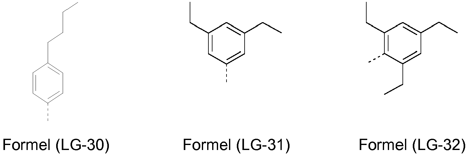
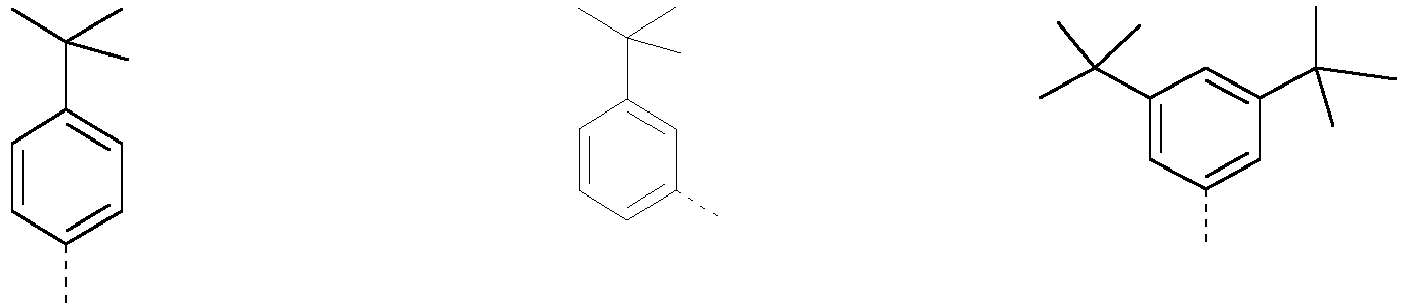


- Eine weitere bevorzugte lösliche Gruppe LG weist die Formel -N(X3)(X4) auf, wobei wenigstens eine der beiden Gruppen X3 und X4 eine der oben genannten löslichen Gruppen (LG-1) bis (LG-55) ist, wobei ganz bevorzugt ist, wenn beide Gruppen X3 und X4 aus den oben genannten löslichen Gruppen (LG-1) bis (LG-55) ausgewählt sind. Besonders bevorzugt ist, wenn beide Gruppen X3 und X4 aus den oben genannten löslichen Gruppen (LG-1) bis (LG-55) ausgewählt sind und zudem identisch sind.
- Sofern nur eine der beiden Gruppen X3 und X4 eine der Gruppen (LG-1) bis (LG-55) darstellt, ist die andere Gruppe bevorzugt eine Aryl- oder Heteroarylgruppe, welche mit einem oder mehreren Resten R1 substituiert sein kann, wobei ganz bevorzugt ist wenn es sich um eine Phenyl-, Biphenyl-, Terphenyl- oder Quarterphenylgruppe handelt, die mit einem oder mehreren Resten R1 substituiert sein kann, wobei besonders bevorzugt ist, wenn es sich um eine unsubstituierte Phenyl-, Biphenyl-, Terphenyl- oder Quarterphenylgruppe handelt.
- Weitere bevorzugte Gruppen LG sind solche, die dadurch erhalten werden, dass eine oder mehrere der oben genannten Gruppen (LG-1) bis (LG-55) an eine Phenylengruppe gebunden sind. Beispielsweise können mit Hilfe des Gruppe (LG-8) auch folgende löslichkeitsvermittelnde Gruppen aufgebaut werden:

- Bevorzugte Gruppen LG sind also auch solche der folgenden Formel (LGX)

- wobei der Index x für eine ganze Zahl von 1 bis 5 steht, bevorzugt steht Index x für 1 oder 2;
- BX ist gleich oder verschieden voneinander eine Gruppe der Formeln (LG-1) bis (LG-55).
- Weiterhin bevorzugt sind solche Gruppen LG, die eine der Gruppen der Formeln (LG-1) bis (LG-55) oder (LGX) enthalten.
- In einer bevorzugten Ausführungsform enthält die Verbindung der allgemeinen Formel (1) in den Gruppen A, D und den Gruppen der Formeln (LG-1) bis (LG-55), bevorzugt 3 bis 15, ganz bevorzugt 3 bis 12, ganz besonders bevorzugt 3 bis 10 und insbesondere 4 bis 10 aromatische Ringe.
- Weiterhin bevorzugt ist, wenn die Verbindung der Formel (1) wenigstens einen heterocyclischen Ring enthält.
- Ganz bevorzugt enthält die Verbindung der allgemeinen Formel (1) wenigstens einen heteroaromatischen Ring oder ein heteroaromatisches Ringsystem.
- Bei der TADF-Verbindung handelt es sich bevorzugt um eine aromatische Verbindung, die sowohl Donor- wie auch Akzeptorsubstituenten aufweist, wobei das LUMO und das HOMO der Verbindung räumlich nur schwach überlappen. Was unter Donor- bzw. Akzeptorsubstituenten verstanden wird, ist dem Fachmann prinzipiell bekannt und oben bereits erläutert worden. Geeignete Donorsubstituenten sind insbesondere Diaryl- bzw. -heteroarylaminogruppen sowie Carbazolgruppen bzw. Carbazolderivate, die jeweils bevorzugt über N an die aromatische Verbindung gebunden sind. Dabei können diese Gruppen auch weiter substituiert sein. Geeignete Akzeptorsubstituenten sind insbesondere Cyanogruppen, aber auch beispielsweise elektronenarme Heteroarylgruppen, die auch weiter substituiert sein können.
- In einer bevorzugten Ausführungsform betrifft die vorliegende Erfindung eine organische TADF-Verbindung der allgemeinen Formel (1) mit einer geringen räumlichen Überlappung der Molekülorbitale A, die bei bestimmten elektronischen Übergängen beteiligt sind (Charge-Transfer-Zustände).
- Die Überlappung der Molekülorbitale A wird vorliegend mit Hilfe eines quantenchemischen Verfahrens ermittelt, das im Beispielteil ausführlich offenbart ist.
- Vorliegend bedeutet eine geringe Überlappung der Molekülorbitale, dass der Wert des Parameters A 0.3 oder kleiner ist, bevorzugt ist er 0.2 oder kleiner, ganz bevorzugt ist er 0.15 oder kleiner, ganz besonders bevorzugt ist er 0.1 oder kleiner und insbesondere bevorzugt ist er 0.05 oder kleiner.
- Orbitalenergien sowie die Überlappung der Molekülorbitale werden vorliegend mit Hilfe quantenchemischer Verfahren ermittelt, die im Beispielteil ausführlich allgemein offenbart werden.
- Weiterhin ist es bevorzugt, wenn die organische TADF-Verbindung eine kurze Abklingzeit aufweist. Dabei ist die Abklingzeit bevorzugt kleiner oder gleich 50 µs. Wie die Bestimmung der Abklingzeit im Sinne der vorliegenden Erfindung durchgeführt wird, ist im Beispielteil ausführlich allgemein offenbart.
- Besonders bevorzugte TADF-Verbindungen im Sinne der vorliegenden Erfindung sind solche der allgemeinen Formel (2),

- Die ein oder mehrere Gruppen LG binden hierbei bevorzugt an die eine oder die mehreren Gruppen D.
- Ganz besonders bevorzugte TADF-Verbindungen sind dabei solche der Formel (3), wobei pp gleich 1, 2 oder 3 ist, bevorzugt ist pp gleich 1 oder 2 und ganz bevorzugt ist pp gleich 2.

- Insbesondere bevorzugte TADF-Verbindungen sind dabei solche der Formel (4).

- Weiterhin insbesondere bevorzugte TADF-Verbindungen sind dabei solche der Formel (5), wobei pp gleich oder verschieden sein kann bei jedem Auftreten; q', q" und q'" sind unabhängig voneinander 0 oder 1 wobei die Summe q'+q"+q''' 1, 2 oder 3 beträgt.

- Weiterhin insbesondere bevorzugte TADF-Verbindungen sind dabei solche der Formel (6), wobei pp gleich oder verschieden sein kann bei jedem Auftreten; q', q", q'" und q'''' sind unabhängig voneinander 0 oder 1 wobei die Summe q'+q"+q'''+q'''' 1, 2, 3 oder 4 beträgt.

- Weiterhin insbesondere bevorzugte TADF-Verbindungen sind dabei solche der Formel (7), wobei pp gleich oder verschieden sein kann bei jedem Auftreten; q' und q" sind unabhängig voneinander 0 oder 1 wobei die Summe q'+q" 1 oder 2 beträgt.

- Weiterhin insbesondere bevorzugte TADF-Verbindungen sind dabei solche der Formel (8), wobei pp gleich oder verschieden sein kann bei jedem Auftreten; q', q" und q'" sind unabhängig voneinander 0 oder 1 wobei die Summe q'+q"+q''' 1, 2 oder 3 beträgt

- Es ist ferner besonders bevorzugt, wenn A in den Verbindungen der Formeln (2) bis (8) gleich CN ist. Es ist noch bevorzugter, wenn A in den Verbindungen der Formeln (2) bis (8) gleich CN ist und D ein Carbazol darstellt, wobei das Carbazol mit einem oder mehreren Resten R1 weiter substituiert sein kann.
- Besonders bevorzugte TADF-Verbindungen im Sinne der vorliegenden Erfindung sind solche der allgemeinen Formel (9), wobei das Spirobifluoren mit einem oder mehreren Resten R1, die gleich oder verschieden sein können bei jedem Auftreten, substituiert sein kann.

- Ganz besonders bevorzugte TADF-Verbindungen sind dabei auch solche der Formel (10).
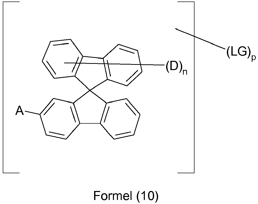
- Insbesondere bevorzugte TADF-Verbindungen sind dabei solche der Formel (11), wobei pp gleich 1, 2 oder 3 ist, bevorzugt ist pp gleich 1 oder 2 und ganz bevorzugt ist pp gleich 2.

- Ferner ganz besonders bevorzugte TADF-Verbindungen sind dabei auch solche der Formel (12).

- Insbesondere bevorzugte TADF-Verbindungen sind dabei solche der Formel (13), wobei pp gleich 1, 2 oder 3 ist, bevorzugt ist pp gleich 1 oder 2 und ganz bevorzugt ist pp gleich 2.

- Ferner ganz besonders bevorzugte TADF-Verbindungen sind solche der Formel (14).


- Insbesondere bevorzugte TADF-Verbindungen sind dabei solche der Formel (15), wobei pp gleich oder verschieden sein kann bei jedem Auftreten; q' und q" sind unabhängig voneinander 0 oder 1 wobei die Summe q'+q" 1 oder 2 beträgt.

- Weiterhin insbesondere bevorzugte TADF-Verbindungen sind dabei solche der Formel (16), wobei pp gleich 1, 2 oder 3 ist, bevorzugt ist pp gleich 1 oder 2 und ganz bevorzugt ist pp gleich 2.

- Weiterhin ganz besonders bevorzugte TADF-Verbindungen sind solche der Formel (17)

- Insbesondere bevorzugte TADF-Verbindungen sind dabei solche der Formel (18), wobei pp gleich oder verschieden sein kann bei jedem Auftreten; q' und q" sind unabhängig voneinander 0 oder 1 wobei die Summe q'+q" 1 oder 2 beträgt.

- Weiterhin insbesonders bevorzugte TADF-Verbindungen sind dabei solche der Formel (20), wobei pp gleich 1, 2 oder 3 ist, bevorzugt ist pp gleich 1 oder 2 und ganz bevorzugt ist pp gleich 2.

- Weiterhin ganz besonders bevorzugte TADF-Verbindungen sind solche der Formel (21)

- Insbesonders bevorzugte TADF-Verbindungen sind dabei solche der Formel (22), wobei pp gleich oder verschieden sein kann bei jedem Auftreten; q' und q" sind unabhängig voneinander 0 oder 1 wobei die Summe q'+q" 1 oder 2 beträgt.


- Weiterhin insbesonders bevorzugte TADF-Verbindungen sind dabei solche der Formel (23), wobei pp gleich 1, 2 oder 3 ist, bevorzugt ist pp gleich 1 oder 2 und ganz bevorzugt ist pp gleich 2.
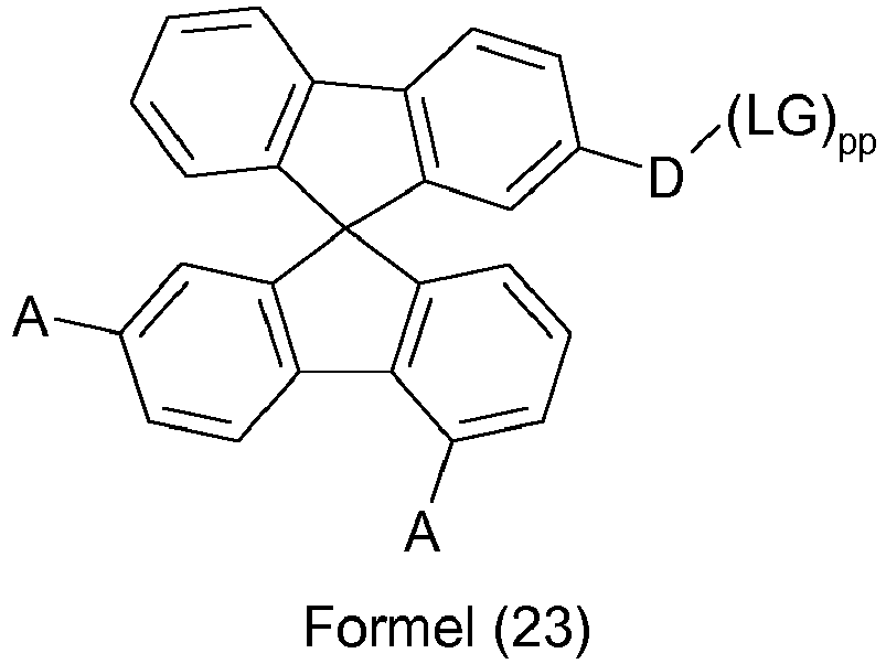
- Weiterhin insbesondere bevorzugte TADF-Verbindungen sind dabei solche der Formel (24), wobei pp gleich 1, 2 oder 3 ist, bevorzugt ist pp gleich 1 oder 2 und ganz bevorzugt ist pp gleich 2.

- Die ein oder mehreren Gruppen LG in den Verbindungen der Formeln (6) bis (24) binden hierbei bevorzugt an Gruppe(n) D.
- Ganz besonders bevorzugte TADF-Verbindungen sind dabei auch solche der Formel (25).

- Ferner ganz besonders bevorzugte TADF-Verbindungen sind solche der Formel (26)

- Insbesondere bevorzugte TADF-Verbindungen sind dabei solche der Formel (27).

- Ganz besonders bevorzugte TADF-Verbindungen sind dabei auch solche der Formeln (28) und (29).
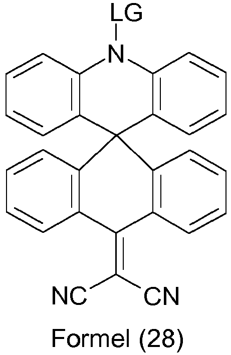
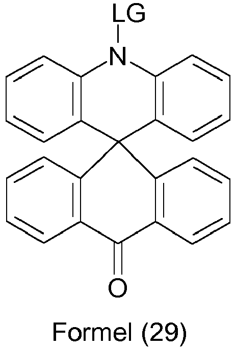
- Die Verbindungen der Formeln (2) bis (29) können dabei mit einem oder mehreren Resten R1, die gleich oder verscheiden sein können bei jedem Auftreten, substituiert sein.
- Die folgende Übersicht enthält eine exemplarische Übersicht erfindungsgemäßer TADF-Verbindungen.


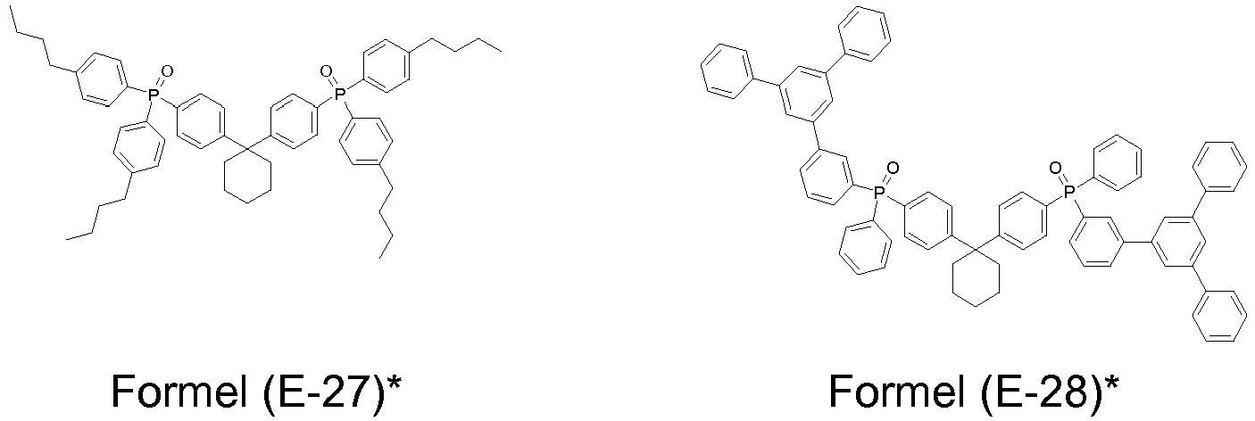


- Die erfindungsgemäßen Verbindungen können nach Verfahren hergestellt werden, die dem Fachmann gut bekannt sind. In den Beispielen werden verschiedene Verfahren offenbart.
- Die erfindungsgemäßen organischen TADF-Verbindungen oder Zusammensetzungen enthaltend die erfindungsgemäßen organischen TADF-Verbindungen können in elektronischen Vorrichtungen, insbesondere in organischen Elektrolumineszenzvorrichtungen wie den organischen lichtemittierenden Dioden (OLEDs) und den organischen lichtemittierenden elektrochemischen Zellen (OLECs) eingesetzt werden.
- Die vorliegende Erfindung betrifft daher auch eine Zusammensetzung enthaltend wenigstens eine erfindungsgemäße TADF-Verbindung und wenigstens ein weiteres organisches funktionelles Material und/oder ein anorganisches Nanoteilchen.
- Das weitere organische funktionelle Material ist dabei bevorzugt ausgewählt aus der Gruppe der elektronleitenden Materialien (ETM), elektroninjizierenden Materialien (EIM), elektronenblockierenden Materialien (EBM), lochleitenden Materialien (HTM), lochinjizierenden Materialien (HIM), lochblockierenden Materialien (HBM), fluoreszierenden Emittern, phosphoreszierenden Emittern und Matrixmaterialien, wobei Matrixmaterialien besonders bevorzugt sind.
- Dem Fachmann sind diese organischen funktionellen Materialien gut bekannt und er kann ohne Schwierigkeiten aus einer Vielzahl ihm bekannter Materialien und unter Heranziehung gängiger Überlegungen die jeweils geeigneten Materialien für die Zusammensetzung auswählen.
- Fluoresziernde Emitter (auch fluoreszierende Dotanden genannt) im Sinne der vorliegenden Erfindung sind Verbindungen, bei denen die Lichtemission durch einen spin-erlaubten Übergang erfolgt, vorzugsweise handelt es sich hierbei um einen Übergang aus einem angeregten Singulett-Zustand.
- Vom Begriff phosphoreszierende Emitter (auch phosphoreszierende Dotanden genannt) sind typischerweise Verbindungen umfasst, bei denen die Lichtemission durch einen spin-verbotenen Übergang erfolgt, beispielsweise einen Übergang aus einem Triplett-Zustand oder einem Zustand mit einer höheren Spinquantenzahl, beispielsweise einem Quintett-Zustand, vorzugsweise handelt es sich bei den phosphoreszierenden Emittern um Verbindungen, die Licht aus einem angeregten Triplett-Zustand emittieren.
- Als phosphoreszierende Dotanden eignen sich insbesondere Verbindungen, die bei geeigneter Anregung Licht, vorzugsweise im sichtbaren Bereich, emittieren und außerdem mindestens ein Atom der Ordnungszahl größer 20, bevorzugt größer 38 und kleiner 84, besonders bevorzugt größer 56 und kleiner 80 enthalten. Bevorzugt werden als phosphoreszierende Dotanden Verbindungen, die Kupfer, Molybdän, Wolfram, Rhenium, Ruthenium, Osmium, Rhodium, Iridium, Palladium, Platin, Silber, Gold oder Europium enthalten, verwendet, insbesondere Verbindungen, die Iridium, Platin oder Kupfer enthalten.
- Die TADF-Verbindung wird dabei bevorzugt als lumineszierende Verbindung in der Emissionsschicht einer Elektrolumineszenzvorrichtung verwendet.
- Eine lumineszente Verbindung im Sinne der vorliegenden Erfindung ist eine Verbindung, die in der Lage ist, unter optischer Anregung in einer Umgebung, wie sie in der organischen Elektrolumineszenzvorrichtung vorliegt, bei Raumtemperatur Licht zu emittieren. Dabei weist die Verbindung bevorzugt eine Lumineszenzquanteneffizienz von mindestens 40 % auf, besonders bevorzugt von mindestens 50 %, ganz besonders bevorzugt von mindestens 60 % und insbesondere bevorzugt von mindestens 70 %. Dabei wird die Lumineszenzquanteneffizienz bestimmt in einer Schicht in Mischung mit dem Matrixmaterial, wie sie in der organischen Elektrolumineszenzvorrichtung verwendet werden soll. Wie die Bestimmung der Lumineszenzquantenausbeute im Sinne der vorliegenden Erfindung durchgeführt wird, ist im Beispielteil ausführlich allgemein beschrieben.
- Die organische TADF-Verbindung liegt vorzugsweise in der emittierenden Schicht einer organischen Elektrolumineszenzvorrichtung vor. Die erfindungsgemäßen TADF-Verbindungen können dabei sowohl als Emitter als auch als Matrix eingesetzt werden, wobei bevorzugt ist, wenn sie als Emitter verwendet werden. Wenn sie als Emitter in einer Emissionsschicht verwendet werden, liegen sie bevorzugt in einer Matrix vor. Die Matrix kann hierbei aus nur einem Material oder aus mehreren Materialien (mixed Matrix) bestehen. Dabei trägt das Matrixmaterial nicht oder nicht wesentlich zur Emission der Mischung bei.
- Um Exziplexbildung in der emittierenden Schicht zu vermeiden, ist es bevorzugt, wenn für LUMO(TADF), also das LUMO der TADF-Verbindung, und das HOMO(Matrix) gilt:


- Dabei ist S1(TADF) der erste angeregte Singulettzustand S1 der TADF-Verbindung.
- Damit die TADF-Verbindung die emittierende Verbindung in der Mischung der emittierenden Schicht ist, ist es bevorzugt, dass die niedrigste Triplettenergie der Matrix maximal 0.1 eV niedriger ist als die Triplettenergie des Moleküls, welches TADF zeigt. Insbesondere bevorzugt ist T1 (Matrix) ≥ T1 (TADF). Besonders bevorzugt gilt: T1 (Matrix) - T1 (TADF) ≥ 0.1 eV, ganz besonders bevorzugt T1 (Matrix) - T1 (TADF) ≥ 0.2 eV. Dabei steht T1 (Matrix) für die niedrigste Triplettenergie der Matrixverbindung und T1 (TADF) für die niedrigste Triplettenergie der Verbindung, die TADF zeigt. Dabei wird die Triplettenergie der Matrix, nach dem im Beispielteil ausführlich allgemein offenbarten Verfahren, durch quantenchemische Rechnung bestimmt.
- Beispiele für geeignete Matrixmaterialien sind Lactame, z.B. gemäß
WO 2011/116865A1 ,WO 2013/064206A1 ,WO 2014/056567A1 ,WO 2014/094964A1 ,Ketone, Phosphinoxide, Sulfoxide und Sulfone, z. B. gemäßWO 2004/013080 ,WO 2004/093207 ,WO 2006/005627 oderWO 2010/006680 , Triarylamine, Carbazolderivate, z. B. CBP (N,N-Bis-carbazolylbiphenyl), m-CBP oder die inWO 2005/039246 ,US 2005/0069729 ,JP 2004/288381 EP 1205527 ,WO 2008/086851 oderUS 2009/0134784 offenbarten Carbazolderivate, Indolocarbazolderivate, z. B. gemäßWO 2007/063754 oderWO 2008/056746 , Indenocarbazolderivate, z. B. gemäßWO 2010/136109 oderWO 2011/000455 , Azacarbazole, z. B. gemäßEP 1617710 ,EP 1617711 ,EP 1731584 ,JP 2005/347160 WO 2007/137725 , Silane, z. B. gemäßWO 2005/111172 , Azaborole oder Boronester, z. B. gemäßWO 2006/117052 , Diazasilolderivate, z. B. gemäßWO 2010/054729 , Diazaphospholderivate, z. B. gemäßWO 2010/054730 , Triazinderivate, z. B. gemäßWO 2010/015306 ,WO 2007/063754 oderWO 2008/056746 , Zinkkomplexe, z. B. gemäßEP 652273 WO 2009/062578 , oder verbrückte Carbazolderivate, z. B. gemäßUS 2009/0136779 ,WO 2010/050778 ,WO 2011/042107 oderWO 2011/088877 . - Die erfindungsgemäßen TADF-Verbindungen und die erfindungsgemäßen Zusammensetzungen eignen sich sehr gut, um elektronische Vorrichtungen, insbesondere organische Elektrolumineszenzvorrichtungen leicht und kostengünstig aus Lösung herzustellen. Zur Herstellung aus der Lösung werden Formulierungen benötigt. Die so hergestellten elektronischen Vorrichtungen weisen dabei sehr gute Leistungsdaten auf. Weiterhin zeigt es sich, dass die so hergestellten elektronischen Vorrichtungen weniger Ausfallraten bei der Herstellung der Vorrichtungen aufweisen. Die Formulierungen eignen sich somit für eine kostengünstige und zuverlässige Massenproduktion elektronischer Vorrichtungen für die kommerzielle Anwendung.
- Daher betrifft die vorliegende Erfindung auch eine Formulierung enthaltend wenigstens eine erfindungsgemäße TADF-Verbindung oder wenigstens eine erfindungsgemäße Zusammensetzung sowie wenigstens ein Lösungsmittel.
- Unter Formulierung wird vorliegend eine Zusammensetzung verstanden, die neben dem wenigstens einen organischen TADF-Molekül, den möglichen weiteren organischen funktionellen Materialien noch ein organisches Lösungsmittel oder organisches Lösungsmittelgemisch enthält. Das Lösungsmittel oder Lösungsmittelgemisch ist dabei bevorzugt im Überschuss vorhanden.
- Unter Lösungsmittelgemisch wird vorliegend eine Mischung von wenigstens zwei unterschiedlichen Lösungsmitteln verstanden.
- Weiterhin bevorzugt ist, dass die Formulierung in flüssiger Form vorliegt. Die Formulierung kann dabei eine echte Lösung, eine Emulsion, Miniemulsion, Dispersion oder Suspension darstellen, wobei ganz bevorzugt ist, wenn die Formulierung eine echte Lösung ist.
- Die Formulierung wird zur Herstellung einer Schicht organischer elektronischer Vorrichtungen, insbesondere der Emissionsschicht organischer Elektrolumineszenzvorrichtungen, verwendet. Während der Herstellung der Schicht wird das Lösungsmittel oder das Lösungsmittelgemisch entfernt, so dass die TADF-Verbindung(en) und die potentiellen weiteren organischen funktionellen Materialien in der Schicht im Überschuss gegenüber dem verbleibenden Lösungsmittel oder Lösungsmittelgemisch vorliegen. Vorzugsweise findet sich das Lösungsmittel oder Lösungsmittelgemisch, wenn überhaupt, nur noch in Spuren in der Schicht der organischen elektronischen Vorrichtung. Ganz bevorzugt ist, wenn das Lösungsmittel oder Lösungsmittelgemisch vollständig entfernt wurde und daher nicht mehr in der aufgebrachten Schicht aufzufinden ist.
- Bevorzugt ist, wenn das verwendetet Lösungsmittel oder die Lösungsmittel (im Fall eines Lösungsmittelgemischs) eine Oberflächenspannung von wenigstens 28 mN/m, bevorzugt wenigstens 30 mN/m, ganz bevorzugt wenigstens 32 mN/m und ganz besonders bevorzugt wenigstens 35 mN/m aufweist.
- Weiterhin bevorzugt ist, wenn die Siede- oder Sublimationstemperatur des Lösungsmittels oder der Lösungsmittel kleiner als 300°C und bevorzugt weniger als 260°C beträgt.
- Ganz bevorzugt ist, wenn die Viskosität des Lösungsmittel oder der verschiedenen Lösungsmittel eines Lösungsmittelgemischs größer als 3mPa∗s und bevorzugt größer als 5mPa∗s ist.
- Weiterhin bevorzugt ist, wenn das Molekulargewicht des Lösungsmittels oder der Lösungsmittel kleiner oder gleich 1000 g/mol, bevorzugt kleiner oder gleich 700 g/mol, ganz bevorzugt kleiner oder gleich 500 g/mol und besonders bevorzugt kleiner oder gleich 300 g/mol ist.
- Wie bereits erläutert liegt das Lösungsmittel bzw. sind die Lösungsmittel eines Lösungsmittelgemischs in der Formulierung im Überschuss vor im Vergleich zu der TADF-Verbindung.
- Die Formulierung der vorliegenden Erfindung kann bevorzugt 0,01 bis 20 Gew.-%, ganz bevorzugt 0,05 bis 10 Gew.-%, besonders bevorzugt 0,1 bis 5 Gew.-% und insbesondere bevorzugt 0,5 bis 5 Gew.-% niedermolekulare organische Halbleitermaterialien enthalten, wobei unter niedermolekularen organischen Halbleitermaterialien die erfindungsgemäßen TADF-Verbindungen sowie die oben bereits genannten weiteren organischen funktionellen Materialien verstanden werden, deren Molekulargewicht kleiner oder gleich 4000 g/mol, bevorzugt kleiner oder gleich 3000 g/mol, ganz bevorzugt kleiner oder gleich 2000 g/mol, ganz besonders bevorzugt kleiner oder gleich 1500 und insbesondere bevorzugt kleiner oder gleich 1000 g/mol ist.
- Der Fachmann kann aus einer Vielzahl von Lösungsmitteln und Lösungsmittelgemischen auswählen, um die erfindungsgemäßen Formulierungen bereitzustellen.
- Geeignete und bevorzugte Lösungsmittel sind beispielsweise Toluol, Anisol, o-, m- oder p-Xylol, Methylbenzoat, Mesitylen, Tetralin, Veratrol, THF, Methyl-THF, THP, Chlorbenzol, Dioxan, Phenoxytoluol, insbesondere 3-Phenoxytoluol, (-)-Fenchon, 1,2,3,5-Tetramethylbenzol, 1,2,4,5-tetramethylbenzol, 1-Methylnaphtalin, 2-Methylbenzothiazol, 2-Phenoxyethanol, 2-Pyrrolidinon, 3-Methylanisol, 4-Methylanisol, 3,4-Dimethylanisol, 3,5-Dimethylanisol, Acetophenon, α-Terpineol, Benzothiazol, Butylbenzoat, Cumol, Cyclohexanol, Cyclohexanon, Cyclohexylbenzol, Decalin, Dodecylbenzol, Ethylbenzoat, Indan, Methylbenzoat, NMP, p-Cymol, Phenetol, 1,4-Diisopropylbenzol, Dibenzyl ether, Diethyhenglycolbutylmethyl ether, Triethyleneglycolbutylmethyl ether, Diethylenglycoldibutyl ether, Triethylenglycoldimethyl ether, Diethylenglycolmonobutylether, Tripropyleneglycol dimethyl ether, Tetraethyleneglycol dimethyl ether, 2-isopropyl naphthalin, Pentylbenzol, Hexylbenzol, Heptylbenzol, octylbenzol, 1,1-Bis(3,4-Dimethylphenyl)ethan oder Mischungen diesen Lösemitteln.
- Die Formulierung der vorliegenden Erfindung enthält ein oder mehrere organische Lösungsmittel, vorzugsweise mindestens ein aromatisches Lösungsmittel. Die Lösungsmittel sind vorzugsweise aus der Gruppe bestehend aus aromatischen Kohlenwasserstoffen, wie Toluol, o-, m- oder p-Xylol, Phenoxytoluole, Trimethylbenzole (z.B. 1,2,3-, 1,2,4- und 1,3,5-Trimethylbenzole), Tetralin, anderen Mono-, Di-, Tri- und Tetraalkylbenzolen (z.B. Diethylbenzole, Methylcumol, Tetramethylbenzole usw.), aromatischen Ethern (z.B. Anisol, Alkylanisole, z.B. 2-, 3- und 4-Isomere des Methylanisols, 2,3-, 2,4-, 2,5-, 2,6-, 3,4- und 3,5-Isomere des Dimethylanisols), Naphthalinderivaten, Alkylnaphthalinderivaten (z.B. 1- und 2- Methylnaphthalin), Di- und Tetrahydronaphthalinderivaten ausgewählt. Ebenfalls bevorzugt sind aromatische Ester (z.B. Alkylbenzoate), aromatische Ketone (z.B. Acetophenon, Propiophenon), Alkylketone (z.B. Cyclohexanon), heteroaromatische Lösungsmittel (z.B. Thiophen, Mono-, Di- und Trialkylthiophene, 2-Alkylthiazole, Benzthiazole usw., Pyridine), Halogenarylene und Anilinderivate. Diese Lösungsmittel können Halogenatome enthalten.
- Besonders bevorzugt sind: 3-Fluor-trifluormethylbenzol, Trifluormethylbenzol, Dioxan, Trifluormethoxybenzol, 4-Fluor-benzoltrifluorid, 3-Fluorpyridin, Toluol, 2-Fluortoluol, 2-Fluor-benzoltrifluorid, 3-Fluortoluol, Pyridin, 4-Fluortoluol, 2,5-Difluortoluol, 1-Chlor-2,4-difluorbenzol, 2-Fluorpyridin, 3-Chlorfluorbenzol, 1-Chlor-2,5-difluorbenzol, 4-Chlorfluorbenzol, Chlorbenzol, 2-Chlorfluorbenzol, p-Xylol, m-Xylol, o-Xylol, 2,6-Lutidin, 2-Fluor-m-xylol, 3-Fluor-o-xylol, 2-Chlorbenzoltrifluorid, Dimethylformamid, 2-Chlor-6-fluortoluol, 2-Fluoranisol, Anisol, 2,3-Dimethylpyrazin, Brombenzol, 4-Fluoranisol, 3-Fluoranisol, 3-Trifluormethylanisol, 2-Methylanisol, Phenetol, Benzoldioxol, 4-Methylanisol, 3-Methylanisol, 4-Fluor-3-methylanisol, 1,2-Dichlorbenzol, 2-Fluorbenzolnitril, 4-Fluorveratrol, 2,6-Dimethylanisol, Anilin, 3-Fluorbenzolnitril, 2,5-Dimethylanisol, 3,4-Dimethylanisol, 2,4-Dimethylanisol, Benzolnitril, 3,5-Dimethylanisol, N,N-Dimethylanilin, 1-Fluor-3,5-Dimethoxybenzol, Phenylacetat, N-Methylanilin, Methylbenzoat, N-Methylpyrrolidon, Morpholin, 1,2-Dihydronaphthalin, 1,2,3,4-Tetrahydronaphthalin, o-Tolunitril, Veratrol, Ethylbenzoat, N,N-Diethylanilin, Propylbenzoat, 1-Methylnaphthalin, Butylbenzoat, 2-Methylbiphenyl, 2-Phenylpyridin oder 2,2'-Bitolyl.
- Besonders bevorzugt sind aromatische Kohlenwasserstoffe, insbesondere Toluol, Phenoxytoluol, Dimethylbenzole (Xylole), Trimethylbenzole, Tetralin und Methylnaphthaline, aromatische Ether, insbesondere Anisol, und aromatische Ester, insbesondere Methylbenzoat.
- Insbesondere bevorzugt sind aromatische Ether, insbesondere Anisol und Derivate davon, wie Alkylanisole, und aromatische Ester, insbesondere Methylbenzoat.
- Diese Lösungsmittel können als Mischung von zwei, drei oder mehr verwendet werden.
- Bevorzugte organische Lösungsmittel können Löslichkeitsparameter nach Hansen von Hd im Bereich von 17,0 bis 23,2 MPa0,5, Hp im Bereich von 0,2 bis 12,5 MPa0,5 und Hh im Bereich von 0,9 bis 14,2 MPa0,5 aufweisen. Besonders bevorzugte organische Lösungsmittel weisen Löslichkeitsparameter nach Hansen von Hd im Bereich von 18,5 bis 21,0 MPa0,5, Hp im Bereich von 2,0 bis 6,0 MPa0,5 und Hh im Bereich von 2,0 bis 6,0 MPa0,5 auf.
Tabelle 2: Löslichkeitsparameter nach Hansen von brauchbaren Lösungsmitteln Lösungsmittel Hd[MPa0,5] Hh[MPa0,5] Hp[MPa0,5] 1,2,3,4-Tetrahydro-1-naphthol 19,6 9,2 12,8 1,2,3,4-Tetrahydronaphthalin 19,1 2,3 4,0 1,2,3,4-Tetramethylbenzol 18,7 1,8 1,6 1,2,3,5-Tetramethylbenzol 18,7 1,8 1,6 1,2,3-Trimethylbenzol 19,0 2,9 1,6 1,2,4,5-Tetramethylbenzol 18,7 1,8 1,6 1,2,4-Trichlorbenzol 20,5 6,9 2,7 1,2,4-Trimethylbenzol 19,0 2,9 1,6 1,2-Dihydronaphthalin 20,1 5,5 4,9 1,2-Dimethylnaphthalin 21,0 1,7 5,2 1,3,3-Trimethyl-2-methylenindol 17,9 1,0 3,0 1,3-Benzodioxol 19,7 7,4 7,9 1,3-Diisopropylbenzol 17,5 0,2 1,1 1,3-Dimethylnaphthalin 21,0 1,7 5,2 1,4-Benzodioxan 19,5 8,7 7,2 1,4-Diisopropylbenzol 17,5 0,6 1,6 1,4-Dimethylnaphthalin 21,0 1,7 5,2 1,5-Dimethyltetralin 19,3 5,5 2,6 1-Benzothiophen 19,7 12,3 6,3 1-Bromnaphthalin 23,1 10,3 6,1 1-Chlormethylnaphthalin 22,1 9,9 5,3 1-Ethylnaphthalin 20,7 7,8 4,4 1-Methoxynaphthalin 21,4 10,5 7,5 1-Methylnaphthalin 21,7 8,4 4,5 1-Methylindan 19,4 5,7 2,5 1-Methylindol 19,2 8,1 10,2 2,3,3-Trimethoxyindolenin 19,6 6,8 4,2 2,3-Benzofuran 21,3 5,5 5,6 2,3-Dihydrobenzofuran 19,9 9,5 6,6 2,3-Dimethylanisol 18,9 4,6 4,5 2,4-Dimethylanisol 18,9 4,6 4,5 2,5-Dimethylanisol 18,9 4,6 4,5 2,6-Diisopropylnaphthalin 18,3 3,5 2,2 2,6-Dimethylanisol 18,9 4,6 4,5 2,6-Dimethylnaphthalin 20,1 5,0 3,0 2-Brom-3-(brommethyl)thiophen 19,3 7,3 6,6 2-Brommethylnaphthalin 22,0 9,4 7,2 2-Bromnaphthalin 23,1 10,3 6,1 2-Ethoxynaphthalin 20,5 10,0 7,0 2-Ethylnaphthalin 20,7 7,8 4,4 2-lsopropylanisol 17,7 4,3 5,4 2-Methylchinolin 20,0 7,8 4,0 2-Methylanisol 18,3 5,1 6,2 2-Methylindol 17,8 9,7 4,8 2-Phenoxyethanol 18,7 8,5 13,0 3,4-Dimethylanisol 18,9 4,6 4,5 3,5-Dimethylanisol 18,9 4,6 4,5 3-Bromchinolin 21,4 8,7 5,1 3-lsopropylbiphenyl 19,1 1,3 1,9 3-Methylanisol 18,7 5,7 5,4 4-Benzylaceton 18,3 8,8 5,0 4-Isopropylbiphenyl 19,0 2,5 1,9 4-Methoxybenzylalkohol 19,0 8,5 13,3 4-Methylanisol 18,6 5,9 7,2 4-Phenyl-2-butanon 18,3 8,8 5,0 5,6,7,8-Tetrahydro-1-naphthol 19,6 7,2 10,9 5,6,7,8-Tetrahydro-2-naphthol 19,6 7,2 10,9 5,6,7,8-Tetrahydro-2-naphthylamin 20,1 7,9 8,6 5,6.7,8-Tetrahydro-1-naphthylamin 20,1 7,9 8,6 5-Decanolid 17,1 7,8 3,8 5-Methoxyindan 19,8 9,8 4,0 5-Methoxyindol 17,4 12,3 7,8 5-tert.-Butyl-m-xylol 17,6 3,4 2,2 6-Methoxy-1,2,3,4-tetrahydronapthalin 19,4 6,8 5,4 6-Methylchinolin 21,7 8,4 4,5 8-Methylchinolin 21,7 8,4 4,5 Acetophenon 18,8 10,8 5,5 Anisol 18,5 5,5 5,2 α-Pinen 17,4 3,0 3,2 Benzonitril 19,2 11,9 4,7 Benzothiazol 21,3 5,5 5,6 Benzylacetat 18,2 7,3 6,4 Benzylalkohol 19,1 6,7 14,2 Brombenzol 19,8 7,6 4,3 Butylbenzol 17,6 2,6 1,7 Butylbenzoat 17,7 5,9 5,2 Cyclohexylbenzol 18,6 1,0 1,6 Decahydronaphthalin 17,5 0,4 1,0 Diphenylether 19,9 2,9 3,3 Ethylphenylketon (Propiophenon) 18,3 8,9 5,3 Ethylbenzol 18,2 2,7 2,1 Ethylbenzoat 18,1 6,6 5,9 Furfurylalkohol 18,1 6,7 11,9 gamma-Terpinen 18,0 2,5 2,8 Hexylbenzol 17,4 2,9 1,6 Indan 19,7 7,3 5,8 Inden 20,3 4,4 5,4 Isoamylbenzol 17,1 3,7 1,8 Isobutyl benzol 17,1 2,9 1,6 Isopropylbenzol (Cumol) 17,8 2,0 1,1 m-Cymol 18,1 2,0 2,1 Mesitylen 19,0 2,9 1,6 Methylbenzoat 18,5 7,9 6,4 Methylphenylacetat 18,2 7,3 6,4 m-Xylol 18,8 3,1 2,7 n-Butoxybenzol 17,5 4,4 4,1 n-Butylbenzol 17,6 2,6 1,7 n-Propylbenzoat 17,8 6,6 6,3 n-Propylbenzol 17,8 3,4 2,8 o-Dichlorbenzol 19,5 8,7 3,3 o-Diethylbenzol 17,7 0,7 1,9 o-Ethyltoluol 18,0 1,9 2,8 o-Xylol 18,4 2,0 2,9 Pentylbenzol 17,4 3,0 1,8 p-Ethyltoluol 18,3 3,5 2,8 Phenetol 18,1 4,6 4,6 Phenylacetat 18,5 7,9 6,4 p-Isopropyltoluol (p-Cymol) 18,0 2,5 2,8 Propiophenon 18,3 8,9 5,3 Propylbenzoat 17,8 6,6 6,3 p-Xylol 18,7 3,3 3,3 sec.-Butylbenzol 17,2 2,2 1,6 t-Butylbenzol 17,2 1,3 2,9 Tetralin 19,1 2,3 4,0 Thiophen 18,8 5,2 7,4 Toluol 18,6 4,0 2,2 Veratrol 18,2 6,3 7,5 Hd bezieht sich auf den Dispersionsbeitrag
Hp bezieht sich auf den polaren Beitrag
Hh bezieht sich auf den Wasserstoffbindungsbeitrag - Vorzugsweise besitzt das Lösungsmittel bei dem verwendeten Druck, ganz bevorzugt bei Atmosphärendruck (1013 hPa), einen Siedepunkt oder eine Sublimationstemperatur von < 300°C, besonders bevorzugt ≤ 260°C, insbesondere bevorzugt ≤ 220°C. Die Verdampfung kann auch beschleunigt werden, z.B. durch Einsatz von Wärme und/oder vermindertem Druck. Durch die Verwendung von Lösungsmitteln mit einem Siedepunkt von mindestens 100°C, vorzugsweise mindestens 130°C lassen sich unerwartete Verbesserungen erreichen.
- Üblicherweise kann das organische Lösungsmittel eine Oberflächenspannung von mindestens 28 mN/m, vorzugsweise mindestens 30 mN/m, besonders bevorzugt mindestens 32 mN/m und insbesondere bevorzugt mindestens 35 mN/m aufweisen. Die Oberflächenspannung kann mit einem Kontaktwinkel-Goniometer FTA (First Ten Angstrom) 125 bei 25°C gemessen werden. Einzelheiten zum Verfahren sind bei First Ten Angstrom, wie von Roger P. Woodward, Ph.D., "Surface Tension Measurements Using the Drop Shape Method" veröffentlicht, erhältlich. Vorzugsweise kann die Pendant-Drop-Methode zur Bestimmung der Oberflächenspannung verwendet werden.
- Für eine grobe Schätzung kann die Oberflächenspannung unter Verwendung der Löslichkeitsparameter nach Hansen nach der in Hansen Solubility Parameters: A User's Handbook, zweite Auflage, C. M. Hansen (2007), Taylor and Francis Group, LLC (HSPiP-Handbuch) dargelegten Formel berechnet werden.

- Hd sich auf den Dispersionsbeitrag bezieht,
- Hp sich auf den polaren Beitrag bezieht,
- Hh sich auf den Wasserstoffbindungsbeitrag bezieht,
- MVol sich auf das molare Volumen bezieht.
- Die Löslichkeitsparameter nach Hansen können nach dem Programm Hansen Solubility Parameters in Practice (HSPiP) (2. Auflage) wie bei Hanson und Abbot et al. erhältlich bestimmt werden.
- Vorzugsweise kann das Lösungsmittel eine relative Verdampfungsgeschwindigkeit (Butylacetat = 100) von mindestens 0,01, vorzugsweise von mindestens 0,1, bevorzugt von mindestens 0,5, besonders bevorzugt von mindestens 5, ganz besonders bevorzugt von mindestens 10 und insbesondere bevorzugt von mindestens 20 aufweisen. Die relative Verdampfungsgeschwindigkeit kann nach DIN 53170: 2009-08 bestimmt werden. Für eine grobe Schätzung kann die relative Verdampfungsgeschwindigkeit unter Verwendung der Löslichkeitsparameter nach Hansen mit dem HSPiP-Programm wie vor- und nachstehend genannt berechnet werden.
- Die Formulierung der vorliegenden Erfindung enthält vorzugsweise mindestens 70 Gew.-%, besonders bevorzugt mindestens 80 Gew.-% und insbesondere bevorzugt mindestens 90 Gew.-% eines oder mehrerer organischer Lösungsmittel bezogen auf die Gesamtmasse der Formulierung.
- Bei einer weiteren bevorzugten Ausführungsform enthält die Formulierung der vorliegenden Erfindung mindestens ein Polymermaterial als inertes Bindemittel. Das bedeutet, dass das Polymer keine Halbleitereigenschaften besitzt oder mit einer der Halbleiterverbindungen in der Zusammensetzung chemisch reagiert. Die geringen Leitungseigenschaften des inerten polymeren Bindemittels können als niedrige Dielektrizitätskonstante bestimmt werden. Bevorzugte Bindemittel gemäß der vorliegenden Erfindung sind Materialien mit niedriger Dielektrizitätskonstante, also solche, die bei 1.000 Hz eine Dielektrizitätskonstante (ε) von 3,3 oder weniger besitzen. Das organische Bindemittel besitzt bei 1.000 Hz vorzugsweise eine Dielektrizitätskonstante von weniger als 3,0, besonders bevorzugt 2,9 oder weniger. Vorzugsweise besitzt das organische Bindemittel bei 1.000 Hz eine Dielektrizitätskonstante von größer 1,7. Mit besonderem Vorzug liegt die Dielektrizitätskonstante des Bindemittels im Bereich von 2,0 bis 2,9. Der Ausdruck "chemisch reagieren" wie vor- und nachstehend verwendet bezeichnet eine mögliche Oxidation oder andere chemische Reaktion des nicht leitenden Zusatzes mit den organischen lichtemittierenden Materialien und/oder Ladungstransportmaterialien unter den für die Herstellung, die Lagerung, den Transport und/oder die Verwendung der Formulierung und der OLED-Vorrichtung verwendeten Bedingungen.
- Vorzugsweise weist das polymere Bindemittel ein gewichtsmittleres Molekulargewicht im Bereich von 1.000 bis 50.000.000 g/mol, besonders bevorzugt 1.500 bis 10.000.000 g/mol und insbesondere bevorzugt 2.000 bis 5.000.000 g/mol auf. Mit Polymeren mit einem gewichtsmittleren Molekulargewicht von vorzugsweise ≥ 10.000 g/mol, besonders bevorzugt ≥ 100.000 g/mol lassen sich überraschende Effekte erzielen.
- Das Polymer kann insbesondere einen Polydispersitätsindex Mw/Mn im Bereich von 1,0 bis 10,0, besonders bevorzugt im Bereich von 1,1 bis 5,0 und insbesondere bevorzugt im Bereich von 1,2 bis 3 besitzen.
- Üblicherweise ist das polymere Bindemittel im Lösungsmittel der vorliegenden Zusammensetzung wie vor- und nachstehend beschrieben dispergierbar oder löslich. Vorzugsweise ist das polymere Bindemittel in dem organischen Lösungsmittel löslich und beträgt die Löslichkeit des polymeren Bindemittels in dem Lösungsmittel mindestens 1 g/l, besonders bevorzugt mindestens 5 g/l und insbesondere bevorzugt mindestens 10 g/l.
- Gemäß einer besonderen Ausführungsform der vorliegenden Erfindung kann die Zusammensetzung vorzugsweise 0,1 bis 10 Gew.-%, besonders bevorzugt 0,25 bis 5 Gew.-% und insbesondere bevorzugt 0,5 bis 4 Gew.-% an polymerem Bindemittel enthalten.
- Gemäß einer besonderen Ausführungsform enthalten die polymeren Bindemittel vorzugsweise von Styrol und/oder Olefinen abgeleitete Wiederholungseinheiten. Bevorzugte polymere Bindemittel können mindestens 80 Gew.-%, vorzugsweise 90 Gew.-% und besonders bevorzugt 99 Gew.-% von Styrolmonomeren und/oder Olefinen abgeleitete Wiederholungseinheiten enthalten.
- Styrolmonomere sind in der Technik gut bekannt. Diese Monomere umfassen Styrol, substituierte Styrole mit einem Alkylsubstituenten in der Seitenkette, wie α-Methylstyrol und α-Ethylstyrol, substituierte Styrole mit einem Alkylsubstituenten am Ring, wie Vinyltoluol und p-Methylstyrol, halogenierte Styrole wie Monochlorstyrole, Dichlorstyrole, Tribromstyrole und Tetrabromstyrole.
- Olefine sind Monomere, die aus Wasserstoff- und Kohlenstoffatomen bestehen. Diese Monomere umfassen Ethylen, Propylen, Butylen, Isopren und 1,3-Butadien.
- Gemäß einem besonderen Aspekt der vorliegenden Erfindung handelt es sich bei dem polymeren Bindemittel um Polystyrol mit einem gewichtsmittleren Molekulargewicht im Bereich von 50.000 bis 2.000.000 g/mol, vorzugsweise 100.000 bis 750.000 g/mol, besonders bevorzugt im Bereich von 150.000 bis 600.000 g/mol und insbesondere bevorzugt im Bereich von 200.000 bis 500.000 g/mol.
- Gemäß einer weiteren Ausführungsform der vorliegenden Erfindung handelt es sich bei dem polymeren Bindemittel um Poly-4-methylstyrol mit einem gewichtsmittleren Molekulargewicht im Bereich von 40.000 bis 120.000 g/mol, besonders bevorzugt im Bereich von 60.000 bis 100.000 g/mol.
- Insbesondere kann es sich bei dem Bindemittel um Poly-α-methylstyrol mit einem gewichtsmittleren Molekulargewicht im Bereich von 1.000 bis 20.000 g/mol, besonders bevorzugt im Bereich von 1.500 bis 6.000 g/mol handeln.
- Brauchbare und bevorzugte polymere Bindemittel weisen Löslichkeitsparameter nach Hansen von Hd im Bereich von 15,7 bis 23,0 MPa0,5, Hp im Bereich von 0,0 bis 20,0 MPa0,5 und Hh im Bereich von 0,0 bis 12,5 MPa0,5 auf. Besonders bevorzugte polymere Bindemittel weisen Löslichkeitsparameter nach Hansen von Hd im Bereich von 17,0 bis 21,0 MPa0,5, Hp im Bereich von 1,0 bis 5,0 MPa0,5 und Hh im Bereich von 2,0 bis 10,0 MPa0,5 auf. Insbesondere bevorzugte polymere Bindemittel weisen Löslichkeitsparameter nach Hansen von Hd im Bereich von 19,0 bis 21,0 MPa0,5, Hp im Bereich von 1,0 bis 3,0 MPa0,5 und Hh im Bereich von 2,5 bis 5,0 MPa0,5 auf.
- Die Löslichkeitsparameter nach Hansen können nach dem Programm Hansen Solubility Parameters in Practice (HSPiP) (2. Auflage) wie bei Hanson und Abbot et al. erhältlich bestimmt werden.
- Beispiele brauchbarer polymerer Bindemittel werden in Tabelle 1 der
WO 2011/076325 A1 offenbart. - Gemäß einer bevorzugten Ausführungsform der vorliegenden Erfindung handelt es sich bei dem inerten Bindemittel um ein Polymer mit einer Glasübergangstemperatur im Bereich von -70 bis 160°C, vorzugsweise 0 bis 150°C, besonders bevorzugt 50 bis 140°C und insbesondere bevorzugt 70 bis 130°C. Die Glasübergangstemperatur lässt sich durch Messen der DSC des Polymers (DIN EN ISO 11357, Erhitzungsgeschwindigkeit 10°C pro Minute) bestimmen.
- Die Formulierung gemäß der vorliegenden Erfindung kann zusätzlich eine oder mehrere weitere Komponenten enthalten, wie beispielsweise oberflächenaktive Verbindungen, Gleitmittel, Netzmittel, Dispergiermittel, Hydrophobiermittel, Haftmittel, Fließverbesserer, Entschäumer, Entgasungsmittel, Verdünnungsmittel, die reaktiv oder nicht reaktiv sein können, Hilfsstoffe, Farbmittel, Farbstoffe oder Pigmente, Sensibilisierer, Stabilisatoren, Nanopartikel oder Inhibitoren. Diese weiteren Komponenten sollten jedoch nicht oxidierend oder anders in der Lage sein, chemisch mit dem organischen Halbleitermaterial zu reagieren oder einen elektrisch dotierenden Effekt auf das organische Halbleitermaterial auszuüben.
- Überraschende Verbesserungen lassen sich mit flüchtigen Netzmitteln erzielen. Der Ausdruck "flüchtig", wie er vor- und nachstehend verwendet wird, bedeutet, dass das Mittel aus dem/den organischen Halbleitermaterial(ien) durch Verdampfen entfernt werden kann, nachdem diese(s) Material(ien) auf ein Substrat einer OLED-Vorrichtung unter Bedingungen (wie Temperatur und/oder verminderter Druck), die diese Materialien oder die OLED-Vorrichtung nicht wesentlich beschädigen, abgeschieden wurden. Das bedeutet vorzugsweise, dass das Netzmittel bei dem verwendeten Druck, sehr bevorzugt bei Atmosphärendruck (1013 hPa) vorzugsweise einen Siedepunkt oder eine Sublimationstemperatur von < 350°C, besonders bevorzugt ≤ 300°C, insbesondere bevorzugt ≤ 250°C besitzt. Die Verdampfung kann auch beschleunigt werden, z.B. durch Einsatz von Wärme und/oder vermindertem Druck.
- Überraschende Wirkungen lassen sich mit Formulierungen erreichen, die flüchtige Komponenten mit ähnlichen Siedepunkten enthalten. Vorzugsweise liegt der Unterschied des Siedepunktes des Netzmittels und des organischen Lösungsmittels im Bereich von -50°C bis 50°C, besonders bevorzugt im Bereich von -30°C bis 30°C und insbesondere bevorzugt im Bereich von -20°C bis 20°C.
- Bevorzugte Netzmittel sind nichtaromatische Verbindungen. Weiteren Vorzug haben nichtionische Verbindungen als Netzmittel. Besonders brauchbare Netzmittel weisen eine Oberflächenspannung von höchstens 35 mN/m, vorzugsweise von höchstens 30 mN/m und besonders bevorzugt von höchstens 25 mN/m auf. Die Oberflächenspannung kann mit einem Kontaktwinkel-Goniometer FTA (First Ten Angstrom) 125 bei 25°C gemessen werden. Einzelheiten zum Verfahren sind bei First Ten Angstrom, wie von Roger P. Woodward, Ph.D., "Surface Tension Measurements Using the Drop Shape Method" veröffentlicht, erhältlich. Vorzugsweise kann die Pendant-Drop-Methode zur Bestimmung der Oberflächenspannung verwendet werden.
- Gemäß einem besonderen Aspekt der vorliegenden Erfindung beträgt der Unterschied der Oberflächenspannung des organischen Lösungsmittels und des Netzmittels bevorzugt mindestens 1 mN/m, vorzugsweise mindestens 5 mN/m und besonders bevorzugt mindestens 10 mN/m.
- Gemäß einem besonderen Aspekt der vorliegenden Erfindung kann das Netzmittel eine relative Verdampfungsgeschwindigkeit (Butylacetat = 100) von mindestens 0,01, bevorzugt von mindestens 0,1, vorzugsweise von mindestens 0,5, besonders bevorzugt von mindestens 5, ganz besonders bevorzugt von mindestens 10 und insbesondere bevorzugt von mindestens 20 aufweisen.
- Unerwartete Verbesserungen lassen sich mit Zusammensetzungen erzielen, die Lösungsmittel und Netzmittel mit einer ähnlichen relativen Verdampfungsgeschwindigkeit (Butylacetat = 100) enthalten.
- Vorzugsweise liegt der Unterschied der relativen Verdampfungsgeschwindigkeit (Butylacetat = 100) des Netzmittels und des organischen Lösungsmittels im Bereich von -20 bis 20, besonders bevorzugt im Bereich von -10 bis 10. Gemäß einer bevorzugten Ausführungsform der vorliegenden Erfindung kann das Verhältnis der relativen Verdampfungsgeschwindigkeit (Butylacetat = 100) des Netzmittels zur relativen Verdampfungsgeschwindigkeit (Butylacetat = 100) des organischen Lösungsmittels im Bereich von 230:1 bis 1:230, vorzugsweise von 20:1 bis 1:20 und besonders bevorzugt von 5:1 bis 1:5 liegen.
- Unerwartete Verbesserungen lassen sich durch Netzmittel erzielen, die ein Molekulargewicht von mindestens 100 g/mol, vorzugsweise mindestens 150 g/mol, besonders bevorzugt mindestens 180 g/mol und insbesondere bevorzugt mindestens 200 g/mol aufweisen.
- Geeignete und bevorzugte Netzmittel, die nicht oxidieren oder auf andere Weise chemisch mit den OSC-Materialien reagieren, sind aus der Gruppe bestehend aus Siloxanen, Alkanen, Aminen, Alkenen, Alkinen, Alkoholen und/oder halogenierten Derivaten dieser Verbindungen ausgewählt. Des weiteren können Fluorether, Fluorester und/oder Fluorketone verwendet werden. Besonders bevorzugt sind diese Verbindungen aus Methylsiloxanen mit 6 bis 20 Kohlenstoffatomen, insbesondere 8 bis 16 Kohlenstoffatomen; C7-C14 Alkanen, C7-C14 Alkenen, C7-C14 Alkinen, Alkoholen mit 7 bis 14 Kohlenstoffatomen, Fluorethern mit 7 bis 14 Kohlenstoffatomen, Fluorestern mit 7 bis 14 Kohlenstoffatomen und Fluorketonen mit 7 bis 14 Kohlenstoffatomen ausgewählt. Insbesondere bevorzugte Netzmittel sind Methylsiloxane mit 8 bis 14 Kohlenstoffatomen.
- Beispiele von Verbindungen, die als Netzmittel brauchbar und bevorzugt sind, sind in der in
WO 2011/076325 A1 offenbart. - Bevorzugt enthält die Formulierung vorzugsweise höchstens 5 Gew.-%, besonders bevorzugt höchstens 3 Gew.-% und insbesondere bevorzugt höchstens 1 Gew.-% an benetzenden Hilfsstoffen. Bevorzugt enthält die Zusammensetzung 0,01 bis 5 Gew.-%, besonders bevorzugt 0,05 bis 3 Gew.-% und insbesondere bevorzugt 0,1 bis 1 Gew.-% Netzmittel.
- Die Formulierungen können mit Hilfe von Verfahren hergestellt werden die dem Fachmann gut geläufig sind. Typischerweise werden die einzelnen Komponenten der Formulierung gemischt und gerührt, ggf. auch unter Zufuhr von Wärme. Häufig wird die Formulierung auch entgast oder mit Inertgasen übersättigten Lösungsmitteln hergestellt. Insgesamt ist darauf zu achten, dass nur Lösungsmittel und andere Komponenten sehr hoher Reinheit verwendet werden, um eine Kontamination der elektronischen Vorrichtungen mit schädlichen Verbindungen zu vermeiden. Insbesondere ist darauf zu achten, dass der Wasser-, Sauerstoff und Halogengehalt in der Formulierung niedrig gehalten wird, da insbesondere die Leistungsdaten organischer Elektrolumineszenzvorrichtungen durch deren Anwesenheit stark beeinträchtigt werden können.
- Die erfindungsgemäße organische TADF-Verbindung kann, wie bereits ausgeführt, als Emitter in elektronischen Vorrichtungen eingesetzt werden. In einer weiteren Ausführungsform der vorliegenden Erfindung kann die TADF-Verbindung auch als Matrixmaterial verwendet werden. In diesem Fall überträgt die TADF-Verbindung seine Energie auf einen Emitter, der letztlich Strahlung aus der elektronischen Vorrichtung emittiert. Hierfür eignet sich grundsätzlich jeder Emitter, also sowohl organische fluoreszierende oder organische phosphoreszierende und auch anorganische Emitter, wie beispielsweise, die Quantenpunkte (quantum dots) und Quantenstäbchen (quantum rods), die gemeinsam auch als Nanoteilchen bezeichnet werden. Die Verwendung von TADF-Verbindungen als Matrix ermöglicht elektronische Vorrichtungen mit besonders vorteihaften Leistungsdaten. Besonders bevorzugt ist, wenn die Emitter ein Nanoteilchen ist.
- Es ist daher sehr vorteilhaft, wenn die Formulierung nanokristalline Verbindungen oder Nanoteilchen enthält. Zu den Nanokristallen und Nanoteilchen zählen die Quantenpunkte (quantum dots, QDs) und Quantenstäbchen (quantum rods, QRs). Mit Hilfe dieser Verbindungen lassen sich effiziente OLEDs und andere organische elektronische Vorrichtungen kostengünstig herstellen, die eine sehr geringe Ausfallrate aufweisen und eine Emission mit schmalen Banden zeigen. Weiterhin lassen sich emittierende Vorrichtungen erhalten, die ausgezeichnete Farbreinheiten und Farbqualitäten (CRI - color rendering index) zeigen. Weiterhin kann die Emissionsfarbe (CIE 1931 RGB) solcher OLEDs sehr leicht und genau eingestellt werden.
- Ganz besonders bevorzugt ist, wenn die Formulierung neben Nanoteilchen und TADF-Verbindung(en) noch weitere Matrixverbindungen enthält, wobei es sich bevorzugt um die oben genannten elektronentransportierenden Matrixverbindungen oder um die oben genannten lochtransportierneden Matrixverbindungen handelt.
- Sowohl Quantenpunkte als auch Quantenstäbchen können sehr einfach hergestellt werden. Die Größe der Teilchen, die bestimmender Faktor für die Farbe der emittierten Strahlung darstellt, ist leicht einzustellen. Weiterhin sind die Quantenpunkte und Quantenstäbchen löslich in vielen gängigen Lösungsmitteln und eignen sich sehr gut für lösungsbasierte Herstellprozesse.
- Die ersten monodispersen kolloidalen Quantenpunkte enthaltend ein halbleitendes Material basierten auf CdE (E = S, Se, Te) und wurden mit Hilfe der sogenannten TOPO (Trioctylphosphinoxid) Methode hergestellt (J. Am. Chem. Soc. 115[19], 8706-8715, 1993).
- Dem Fachmann ist eine Vielzahl von Methoden zur Herstellung von Quantenpunkten und Quantenstäbchen bekannt, wobei bevorzugt lösungsbasierte Methoden kolloidaler Systeme zum kontrollierten Wachstum anorganischer Quantenpunkte eingesetzt werden (Science 271:933 (1996); J. Am. Chem. Soc. 30:7019-7029 (1997); J. Am. Chem. Soc. 115:8706 (1993)).
- Geeignete Halbleiter, die in Quantenpunkten und Quantenstäbchen verwendet werden sind ausgewählt aus der Gruppe bestehend aus
Elementen der Gruppen II bis VI, so wie Z.B. CdSe, CdS, CdTe, ZnSe, ZnO, ZnS, ZnTe, HgS, HgSe, HgTe und Mischungen davon, wie z.B. CdZnSe;
Elementen der Gruppe III bis V, wie z.B. InAs, InP, GaAs, GaP, InN, GaN, InSb, GaSb, AlP, AlAs, AlSb und Mischungen davon, wie z.B. InAsP, CdSeTe, ZnCdSe, InGaAs;
Elementen der Gruppe IV bis VI, wie z.B. PbSe, PbTe and PbS und Mischungen davon;
Elementen der Gruppe III bis VI, wie z.B. InSe, InTe, InS, GaSe und Mischungen davon, wie z.B. InGaSe, InSeS;
Elementen der Gruppe IV Halbleiter, wie z.B. Si and Ge und Mischungen davon, sowie Mischungen der zuvor genannten Materialien. - Weiter geeignete Halbleiter für Quantenpunkte und Quantenstäbchen umfassen solche, die in
US10/796,832 - Es ist bevorzug, wenn die Quantenpunkte oder Quantenstäbchen ausgewählt werden aus Elementen der Gruppen II-VI, III-V, IV-VI und IV Halbleitern, ganz bevorzugt aus ZnO, ZnS, ZnSe, ZnTe, CdS, CdSe, CdTe, HgS, HgSe, HgTe, MgS, MgSe, GeS, GeSe, GeTe, SnS, SnSe, SnTe, PbO, PbS, PbSe, PbTe, GaN, GaP, GaAs, GaSb, InN, InP, InAs, InSb, AlN, AIP, AlAs, AlSb, GaN, GaP, GaAs, GaSb, und einer Kombination aus diesen.
- In QDs and QRs, photoluminescence and electroluminescence arise from the band edge states of the nanoparticle. The radiative band-edge emission from nanoparticles competes with non-radiative decay channel originating from surface electronic states, as reported by X. Peng, et al., J. Am. Chem. Soc. Vol119:7019-7029 (1997).
- Als besonders vorteilhaft haben sich auch Quantenpunkte und Quantenstäbchen gezeigt, die eine Core-Shell Struktur aufweisen (J. Am. Chem. Soc. Vol119:7019-7029 (1997).
- Core-Shell Strukturen können erhalten werden, wenn organometallische Vorstufen, welche die Shell Materialien enthalten, als Vorstufen verwendet werden. Diese Vorstufen werden zu einer Reaktionsmischung mit dem Core-Nanoteilchen gegeben. Weitere Einzelheiten zum Herstellungsverfahren sind dem Fachmann aus dem Stand der Technik gut bekannt.
- In einer bevorzugten Ausführungsform wird ZnS als Shell-Material verwendet.
- Weiter bevorzugt ist, wenn die Quantenpunkte und Quantenstäbchen halbleitende Materialien der Gruppe II- VI, Mischungen davon und Core-Shell Strukturen davon darstellen. Ganz bevorzugt sind dabei CdSe, CdS, CdTe, ZnSe, ZnS, ZnTe, Mischungen davon.
- Die Quantenpunkte und Quantenstäbchen können weitere Liganden enthalten, die an die Oberfläche der Teilchen gebunden sind. Geeignete Liganden hierfür sind im Stand der Technik gut bekannt und sind, beispielsweise, offenbart in
US 10/656910 US 60/578236 US 2007/0034833A1 undUS 20050109989A1 offenbart. - Die hierin verwendeten Begriffe Quantenpunkt und Quantenstäbchen stehen für Nanoteilchen, die im Wesentlichen eine monodisperse Größenverteilung aufweisen. Die Dimension der Teilchen beträgt 500 nm und weniger, bis hin zu einer Dimension von ca. 1 nm. Monodispers bedeutet, dass die Teilchen eine Größenverteilung von +-10% der genannten Dimension der Teilchen aufweist.
- Typische Strukturen und Verfahren zur Herstellung von Quantenstäbchen sind in
US 2013/0135558 A1 offenbart. - Die erfindungsgemäßen Formulierungen können zur Herstellung von Schichten in elektronischen Vorrichtungen verwendet werden, wobei die Schichten, die mittels der erfindungsgemäßen Formulierung hergestellt wird aus Lösung aufgebracht wird.
- Bei der Herstellung organischer elektronischer Vorrichtungen, wie z.B. den OLEDs, wird zwischen zwei grundsätzlich verschiedenen Verfahren unterscheiden. Beim ersten Verfahren werden die relevanten Verbindungen im Vakuum aufgedampft. Dieses Verfahren ist sehr aufwendig und kostenintensiv. Bei dem zweiten Verfahren werden die relevanten Verbindungen aus der Lösung aufgebracht.
- Bestimmte elektronischen Vorrichtungen sind aus Mehrschichtsystemen aufgebaut. Bei der Herstellung solcher Mehrschichtsysteme können beide oben genannte Verfahren eingesetzt werden. Häufig werden einzelne Schichten aufgedampft, während andere Schichten aus Lösung prozessiert werden.
- Ein weiterer Gegenstand der vorliegenden Erfindung ist daher ein Verfahren zur Herstellung einer organischen elektronischen Vorrichtung, dadurch gekennzeichnet, dass wenigstens eine Schicht der elektronischen Vorrichtung mit Hilfe der erfindungsgemäßen Formulierung aus Lösung hergestellt wird.
- Typische Verfahren zur Herstellung von Schichten aus der Lösung sind z. B. das Spincoating, oder ein beliebiges Druckverfahren, wie z. B. Siebdruck, Flexodruck, Offsetdruck oder Nozzle-Printing, besonders bevorzugt aber LITI (Light Induced Thermal Imaging, Thermotransferdruck) oder Ink-Jet Druck (Tintenstrahldruck). Hierfür sind Formulierungen erforderlich.
- Bei den organischen elektronischen Vorrichtungen handelt es sich bevorzugt um eine organische integrierte Schaltung (OIC), einen organischen Feld-Effekt-Transistor (OFET), einen organischen Dünnfilmtransistor (OTFT), eine organisch Elektrolumineszenzvorrichtung, eine organische Solarzelle (OSC), einen organischen optischen Detektor, einen organischen Photorezeptor, bevorzugt aber um eine organische Elektroluminesszenzvorrichtung.
- Ganz bevorzugte organische elektrolumineszierende Vorrichtungen sind die organischen lichtemittierenden Transistoren (OLETs), organischen Feld-Quench-Devices (OFQDs), organischen lichtemittierenden elektrochemischen Zellen (OLECs, LECs, LEECs), organischen Laserdioden (O-Laser) und organischen lichtemittierenden Dioden (OLEDs), bevorzugt OLECs und OLEDs, ganz bevorzugt OLEDs.
- Die organische Elektrolumineszenzvorrichtung enthält Kathode, Anode, emittierende Schicht und auf Kathodenseite daran angrenzend mindestens eine Elektronentransportschicht. Außer diesen Schichten kann sie noch weitere Schichten enthalten, beispielsweise jeweils eine oder mehrere Lochinjektionsschichten, Lochtransportschichten, weitere Elektronentransportschichten, Elektroneninjektionsschichten, Exzitonenblockierschichten, Elektronenblockierschichten und/oder Ladungserzeugungsschichten (Charge-Generation Layers). Es sei aber darauf hingewiesen, dass nicht notwendigerweise jede dieser Schichten vorhanden sein muss.
- In den weiteren Schichten der erfindungsgemäßen organischen Elektrolumineszenzvorrichtung, insbesondere in den Lochinjektions- und -transportschichten und in den Elektroneninjektions- und -transportschichten, können alle Materialien verwendet werden, wie sie üblicherweise gemäß dem Stand der Technik eingesetzt werden. Dabei können die Lochtransportschichten auch p-dotiert bzw. die Elektronentransportschichten auch n-dotiert sein. Dabei wird unter einer p-dotierten Schicht eine Schicht verstanden, in der freie Löcher erzeugt wurden und deren Leitfähigkeit dadurch erhöht ist. Eine umfassende Diskussion von dotierten Transportschichten in OLEDs findet sich in Chem. Rev. 2007, 107, 1233. Besonders bevorzugt ist der p-Dotand in der Lage, das Lochtransportmaterial in der Lochtransportschicht zu oxidieren, hat also ein ausreichend hohes Redoxpotential, insbesondere ein höheres Redoxpotential als das Lochtransportmaterial. Als Dotanden sind prinzipiell alle Verbindungen geeignet, welche Elektronenakzeptorverbindungen darstellen und die Leitfähigkeit der organischen Schicht durch Oxidation des Hosts erhöhen können. Der Fachmann kann im Rahmen seines allgemeinen Fachwissens ohne größeren Aufwand geeignete Verbindungen identifizieren. Insbesondere geeignet als Dotanden sind die in
WO 2011/073149 ,EP 1968131 ,EP 2276085 ,EP 2213662 ,EP 1722602 ,EP 2045848 ,DE 102007031220 ,US 8044390 ,US 8057712 ,WO 2009/003455 ,WO 2010/094378 ,WO 2011/120709 undUS 2010/0096600 offenbarten Verbindungen. - Der Fachmann kann daher ohne erfinderisches Zutun alle für organische Elektrolumineszenzvorrichtungen bekannten Materialien in Kombination mit der emittierenden Schicht enthaltend die erfindungsgemäßen TADF-Verbindungen einsetzen.
- Insbesondere kann es bevorzugt sein, wenn zwischen der erfindungsgemäßen Elektronentransportschicht und der Kathode weitere Elektronentransportschichten und/oder Elektroneninjektionsschichten vorliegen.
- Eine Elektronentransportschicht im Sinne der vorliegenden Erfindung ist eine Schicht, die zwischen der Kathode oder der Elektroneninjektionsschicht und der emittierenden Schicht angeordnet ist. Eine Elektroneninjektionsschicht im Sinne der vorliegenden Erfindung ist eine Schicht, die direkt an die Kathode angrenzt und die eine Schichtdicke von nicht mehr als 5 nm, bevorzugt 0.5 bis 5 nm, aufweist.
- Dabei enthalten bevorzugt alle Elektronentransportschichten, also alle Schichten, die zwischen der Kathode bzw., wenn vorhanden, der Elektroneninjektionsschicht und der emittierenden Schicht vorliegen, mindestens eine Verbindung mit einem LUMO ≤ -2.55 eV.
- Damit die Emission der TADF-Verbindung nicht an der direkt angrenzenden Elektronentransportschicht gelöscht wird, ist es bevorzugt, dass die niedrigste Triplettenergie dieser Elektronentransportschicht maximal 0.1 eV niedriger ist als die Triplettenergie des Moleküls, welches TADF zeigt. Insbesondere bevozugt ist T1(ETL) ≥ T1(TADF). Besonders bevorzugt gilt: T1(ETL) - T1(TADF) ≥ 0.1 eV, ganz besonders bevorzugt T1(ETL) - T1(TADF) ≥ 0.2 eV. Dabei steht T1(ETL) für die niedrigste Triplettenergie der Elektronentransportschicht, die direkt an die emittierende Schicht angrenzt, und T1(TADF) für die niedrigste Triplettenergie der TADF-Verbindung. Dabei wird die Triplettenergie der Materialien der Elektronentransportschicht durch im Beispielteil ausführlich und allgemein offenbarte quantenchemische Verfahren ermittelt. Wenn die Elektronentransportschicht mehr als eine Verbindung enthält, gilt die Bedingung für die Triplettenergie bevorzugt für jede der Verbindungen.
- Die oben genannten Bedingungen für die Triplettenergie sind nur für die direkt an die emittierende Schicht angrenzende Elektronentransportschicht bevorzugt. Sind weitere Elektronentransportschichten vorhanden, die kathodenseitig der direkt an die emittierende Schicht angrenzende Elektronentransportschicht angeordnet sind, so ist für diese weiteren Elektronentransportschichten die Triplettenergie nicht von Bedeutung, so dass hier auch Elektronentransportmaterialien mit einer geringeren Triplettenergie gewählt werden können, beispielsweise Anthracenderivate.
- Die auf Kathodenseite direkt an die emittierende Schicht angrenzende Elektronentransportschicht kann auch als Lochblockierschicht wirken, kann also außer elektronentransportierenden Eigenschaften auch gleichzeitig lochblockierende Eigenschaften aufweisen. Dies ist abhängig von der Lage des HOMO-Niveaus der Schicht. Insbesondere wirkt die Schicht dann als Lochblockierschicht, wenn für das HOMO der Schicht gilt: HOMO(EML) - HOMO(ETL) > 0.2 eV, bevorzugt HOMO(EML) - HOMO(ETL) > 0.3 eV. HOMO(ETL) ist das HOMO des Materials der Elektronentransportschicht. Besteht diese Schicht aus mehreren Materialien, so ist HOMO(ETL) das am höchsten liegende HOMO dieser Materialien. HOMO(EML) ist das HOMO des Materials der emittierenden Schicht. Besteht diese Schicht aus mehreren Materialien, so ist HOMO(EML) das am höchsten liegende HOMO dieser Materialien. Dabei wird das HOMO (highest occupied molecular orbital) jeweils durch quantenchemische Rechnungen bestimmt, wie hinten im Beispielteil allgemein erläutert.
- Zur Klarstellung sei betont, dass es sich bei den Werten für HOMO und LUMO definitionsgemäß um negative Zahlenwerte handelt. Bei dem am höchsten liegenden HOMO bzw. dem höchsten HOMO handelt es sich daher um das betragsmäßig kleinste HOMO, und bei dem am tiefsten liegenden LUMO bzw. dem tiefsten LUMO handelt es sich um das betragsmäßig größte LUMO.
- Die Elektronentransportschicht kann als Reinschicht vorliegen, d. h. nur aus einer Verbindung bestehen, die dann vorzugsweise ein LUMO ≤ -2.55 eV aufweist. Die Schicht kann auch als Mischung vorliegen, wobei dann mindestens eine der Verbindungen vorzugsweise ein LUMO ≤ -2.55 eV aufweist. Diese Verbindung liegt in der Schicht in einem Anteil von bevorzugt mindestens 30 Vol.-%, besonders bevorzugt mindestens 50 Vol.-%, ganz besonders bevorzugt mindestens 70 Vol.-% vor. Insbesondere bevorzugt liegt die Schicht als Reinschicht vor, d. h. sie besteht nur aus einer Verbindung, die vorzugsweise ein LUMO ≤ -2.55 eV aufweist. Wenn die Elektronentransportschicht eine Mischung aus zwei oder mehr Materialien enthält, ist es bevorzugt, wenn jedes dieser Materialien ein LUMO ≤ -2.55 eV aufweist.
- Geeignete Elektronentransportmaterialien zur Verwendung in der Elektronentransportschicht sind ausgewählt aus den Stoffklassen der Triazine, der Pyrimidine, der Lactame, der Metallkomplexe, insbesondere der Be-, Zn- bzw. Al-Komplexe, der aromatischen Ketone, der aromatischen Phosphinoxide, der Azaphosphole, der Azaborole, welche mit mindestens einem elektronenleitenden Substituenten substituiert sind, der Benzimidazole, Oxadiazole und der Chinoxaline.
- Als Kathode der erfindungsgemäßen Elektrolumineszenzvorrichtung sind Metalle mit geringer Austrittsarbeit, Metalllegierungen oder mehrlagige Strukturen aus verschiedenen Metallen bevorzugt, wie beispielsweise Erdalkalimetalle, Alkalimetalle, Hauptgruppenmetalle oder Lanthanoide (z. B. Ca, Ba, Mg, Al, In, Mg, Yb, Sm, etc.). Bei mehrlagigen Strukturen können auch zusätzlich zu den genannten Metallen weitere Metalle verwendet werden, die eine relativ hohe Austrittsarbeit aufweisen, wie z. B. Ag, wobei dann in der Regel Kombinationen der Metalle, wie beispielsweise Mg/Ag, Ca/Ag oder Ba/Ag verwendet werden. Ebenso bevorzugt sind Metalllegierungen, insbesondere Legierungen aus einem Alkalimetall oder Erdalkalimetall und Silber, besonders bevorzugt eine Legierung aus Mg und Ag. Es kann auch bevorzugt sein, zwischen einer metallischen Kathode und dem organischen Halbleiter eine dünne Zwischenschicht eines Materials mit einer hohen Dielektrizitätskonstante einzubringen. Hierfür kommen beispielsweise Alkalimetall- oder Erdalkalimetallfluoride, aber auch die entsprechenden Oxide oder Carbonate in Frage (z. B. LiF, Li2O, CsF, CS2CO3, BaF2, MgO, NaF, etc.). Ebenso kommen organische Alkali- oder Erdalkalikomplexe in Frage, wie z. B. Lithiumchinolinat (LiQ). Die Schichtdicke dieser Schicht, die als Elektroneninjektionsschicht anzusehen ist, beträgt bevorzugt zwischen 0.5 und 5 nm.
- Als Anode der erfindungsgemäßen Elektrolumineszenzvorrichtung sind Materialien mit hoher Austrittsarbeit bevorzugt. Bevorzugt weist die Anode eine Austrittsarbeit größer 4.5 eV vs. Vakuum auf. Hierfür sind einerseits Metalle mit hohem Redoxpotential geeignet, wie beispielsweise Ag, Pt oder Au. Es können andererseits auch Metall/Metalloxid-Elektroden (z. B. Al/Ni/NiOx, Al/PtOx) bevorzugt sein. Dabei muss mindestens eine der Elektroden transparent oder teiltransparent sein, um die Auskopplung von Licht zu ermöglichen. Bevorzugte transparente oder teiltransparente Anodenmaterialien sind leitfähige gemischte Metalloxide. Besonders bevorzugt sind Indium-Zinn-Oxid (ITO) oder Indium-Zink-Oxid (IZO). Bevorzugt sind weiterhin leitfähige, dotierte organische Materialien, insbesondere leitfähige dotierte Polymere.
- Die Vorrichtung wird entsprechend (je nach Anwendung) strukturiert, kontaktiert und schließlich hermetisch versiegelt, da sich die Lebensdauer derartiger Vorrichtungen bei Anwesenheit von Wasser und/oder Luft drastisch verkürzt.
- Weiterhin bevorzugt ist eine organische Elektrolumineszenzvorrichtung, dadurch gekennzeichnet, dass eine oder mehrere Schichten mit einem Sublimationsverfahren beschichtet werden. Dabei werden die Materialien in Vakuum-Sublimationsanlagen bei einem Anfangsdruck kleiner 10-5 mbar, bevorzugt kleiner 10-6 mbar aufgedampft. Es ist aber auch möglich, dass der Anfangsdruck noch geringer ist, beispielsweise kleiner 10-7 mbar.
- Bevorzugt ist ebenfalls eine organische Elektrolumineszenzvorrichtung, dadurch gekennzeichnet, dass eine oder mehrere Schichten mit dem OVPD (Organic Vapour Phase Deposition) Verfahren oder mit Hilfe einer Trägergassublimation beschichtet werden. Dabei werden die Materialien bei einem Druck zwischen 10-5 mbar und 1 bar aufgebracht. Ein Spezialfall dieses Verfahrens ist das OVJP (Organic Vapour Jet Printing) Verfahren, bei dem die Materialien direkt durch eine Düse aufgebracht und so strukturiert werden (z. B. M. S. Arnold et al., Appl. Phys. Lett. 2008, 92, 053301).
- Weiterhin bevorzugt ist eine organische Elektrolumineszenzvorrichtung, dadurch gekennzeichnet, dass eine oder mehrere Schichten aus Lösung, wie z. B. durch Spincoating, oder mit einem beliebigen Druckverfahren, wie z. B. Siebdruck, Flexodruck, Offsetdruck, LITI (Light Induced Thermal Imaging, Thermotransferdruck), Ink-Jet Druck (Tintenstrahldruck) oder Nozzle Printing, hergestellt werden. Hierfür sind lösliche Verbindungen nötig, welche beispielsweise durch geeignete Substitution erhalten werden. Diese Verfahren eignen sich insbesondere auch für Oligomere, Dendrimere und Polymere.
- Diese Verfahren sind dem Fachmann generell bekannt und können von ihm ohne erfinderisches Zutun auf organische Elektrolumineszenzvorrichtungen enthaltend die erfindungsgemäßen Verbindungen angewandt werden.
- Ein weiterer Gegenstand der vorliegenden Erfindung ist daher ein Verfahren zur Herstellung einer erfindungsgemäßen organischen Elektrolumineszenzvorrichtung, dadurch gekennzeichnet, dass mindestens eine Schicht mit einem Sublimationsverfahren aufgebracht wird und/oder dass mindestens eine Schicht mit einem OVPD (Organic Vapour Phase Deposition) Verfahren oder mit Hilfe einer Trägergassublimation aufgebracht wird und/oder dass mindestens eine Schicht aus Lösung, durch Spincoating oder mit einem Druckverfahren aufgebracht wird.
- Die erfindungsgemäßen TADF-Verbindungen, Zusammensetzungen, Formulierungen und Vorrichtungen zeichnen sich durch einen oder mehrere der folgenden überraschenden Vorteile gegenüber dem Stand der Technik aus:
- 1. Die erfindungsgemäßen organischen TADF-Verbindungen lassen sich sehr leicht herstellen.
- 2. Die erfindungsgemäßen organischen TADF-Verbindungen weisen eine verbesserte Löslichkeit in organischen Lösungsmitteln auf, die typischerweise zur Herstellung elektronischers Vorrichtungen eingesetzt werden.
- 3. Vorrichtungen, insbesondere organische Elektrolumineszenzvorrichtungen hergestellt mit Hilfe der erfindungsgemäßen Formulierungen weisen vergleichbare Effizienzen und Spannungen auf im Vergleich zu Vorrichtungen aus dem Stand der Technik.
- 4. Organische elektronische Vorrichtungen, insbesondere organische Elektrolumineszenzvorrichtungen hergestellt mit Hilfe der erfindungsgemäßen Formulierungen sind leicht und kostengünstig herzustellen und eignen sich daher besonders gut für die Massenproduktion kommerzieller Produkte.
- 5. Mit Hilfe der erfindungsgemäßen Formulierungen können auf sehr einfache und kostengünstige Weise Schichten organischer elektronischer Vorrichtungen, insbesondere in organischen Elektrolumineszenzvorrichtungen hergestellt werden, die mehrere Komponenten, beispielsweise mehrere Matrixverbindungen, enthalten.
- 6. Mit Hilfe der erfindungsgemäßen Formulierungen können die Herstellverfahren sehr leicht an neue Anforderungen angepasst werden.
- 7. Die Verwendung der erfindungsgemäßen Formulierungen zur Herstellung organischer elektronischer Vorrichtungen führt zu sehr zuverlässigen Produktionsprozessen, insbesondere auch aufgrund einer verringerten Ausfallrate.
- 8. Die Anzahl der Kurzschlüsse in den elektronischen Vorrichtungen enthaltend die erfindungsgemäßen Verbindungen oder Zusammensetzungen sind deutlich verringert gegenüber den Vorrichtungen aus dem Stand der Technik.
- 9. Die Stabilität der Emitter in der Emissionsschicht kann durch Verwendung der TADF-Verbindungen gegenüber dem Stand der Technik verbessert werden.
- 10. Die erfindungsgemäßen Verbindungen können in höheren Konzentrationen in elektronischen Vorrichtungen eingesetzt werden, was sich vorteilhaft auf die Effizienz der Vorrichtungen auswirkt.
- Es sei darauf hingewiesen, dass Variationen der in der vorliegenden Erfindung beschriebenen Ausführungsformen unter den Umfang dieser Erfindung fallen. Jedes in der vorliegenden Erfindung offenbarte Merkmal kann, sofern dies nicht explizit ausgeschlossen wird, durch alternative Merkmale, die demselben, einem äquivalenten oder einem ähnlichen Zweck dienen, ausgetauscht werden. Somit ist jedes in der vorliegenden Erfindung offenbarte Merkmal, sofern nichts anderes gesagt wurde, als Beispiel einer generischen Reihe oder als äquivalentes oder ähnliches Merkmal zu betrachten.
- Alle Merkmale der vorliegenden Erfindung können in jeder Art miteinander kombiniert werden, es sei denn dass sich bestimmte Merkmale und/oder Schritte sich gegenseitig ausschließen. Dies gilt insbesondere für bevorzugte Merkmale der vorliegenden Erfindung. Gleichermaßen können Merkmale nicht wesentlicher Kombinationen separat verwendet werden (und nicht in Kombination).
- Es sei ferner darauf hingewiesen, dass viele der Merkmale, und insbesondere die der bevorzugten Ausführungsformen der vorliegenden Erfindung selbst erfinderisch und nicht lediglich als Teil der Ausführungsformen der vorliegenden Erfindung zu betrachten sind. Für diese Merkmale kann ein unabhängiger Schutz zusätzlich oder alternativ zu jeder gegenwärtig beanspruchten Erfindung begehrt werden.
- Die mit der vorliegenden Erfindung offengelegte Lehre zum technischen Handeln kann abstrahiert und mit anderen Beispielen kombiniert werden.
- Die Erfindung wird durch die nachfolgenden Beispiele näher erläutert, ohne sie dadurch einschränken zu wollen. Der Fachmann kann aus den Schilderungen die Erfindung im gesamten offenbarten Bereich ausführen und ohne erfinderisches Zutun weitere erfindungsgemäße organische Elektrolumineszenzvorrichtungen herstellen.
- Die HOMO- und LUMO- Energien sowie das Triplettniveau und die Singulettniveaus der Materialien werden über quantenchemische Rechnungen bestimmt. Hierzu wird vorliegend das Programm-paket "Gaussian09, Revision D.01" (Gaussian Inc.) verwendet. Zur Berech-nung organischer Substanzen ohne Metalle (mit Methode "org." bezeichnet) wird zuerst eine Geometrieoptimierung mit der semi-empirischen Methode AM1 (Gaussian-Eingabezeile "# AM1 opt") mit der Ladung (Charge) 0 und der Multiplizität (Multiplicity) 1 durchgeführt. Im Anschluss erfolgt auf Grundlage der optimierten Geo-me-trie eine Energierechnung (single point) für den elektronischen Grundzustand und das Triplett-Niveau. Hierbei wird die TDDFT-Methode (time dependent density functional theory) B3PW91 mit dem Basissatz 6-31 G(d) (Gaussian-Eingabezeile "# B3PW91/6-31G(d) td=(50-50,nstates=4)") verwendet (Ladung 0, Multiplizität 1). Für metallorganische Verbindungen (mit Methode "M-org." bezeichnet) wird die Geometrie mit der Methode Hartree-Fock und dem Basissatz LanL2MB (Gaussian-Eingabezeile "# HF/LanL2MB opt") optimiert (Ladung 0, Multiplizität 1). Die Energierechnung erfolgt, wie oben beschrieben, analog zu der der organischen Substanzen, mit dem Unterschied, dass für das Metallatom der Basissatz "LanL2DZ" und für die Liganden der Basissatz "6-31 G(d)" verwendet wird (Gaussian-Eingabezeile "#B3PW91/gen pseudo=lanl2 td=(50-50,nstates=4)"). Aus der Energierechnung erhält man das HOMO als das letzte mit zwei Elektronen besetze Orbital (Alpha occ. eigenvalues) und LUMO als das erste unbesetzte Orbital (Alpha virt. eigenvalues) in Hartree-Einheiten, wobei HEh und LEh für die HOMO Energie in Hartree-Einheiten beziehungsweise für die LUMO-Energie in Hartree-Einheiten steht. Daraus wird der anhand von Cyclovoltammetriemessungen kalibrierte HOMO- und LUMO-Wert in Elektronenvolt wie folgt bestimmt:


- Diese Werte sind im Sinne dieser Anmeldung als HOMO bzw. als LUMO der Materialien anzusehen.
- Das Triplett-Niveau T1 eines Materials ist definiert als die relative Anregungsenergie (in eV) des Triplettzustands mit der niedrigsten Energie, der sich aus der quanten-chemischen Energierechnung ergibt.
- Das Singulett-Niveau S1 eines Materials ist definiert als die relative Anregungsenergie (in eV) des Singulettzustands mit der zweitniedrigsten Energie, der sich aus der quanten-chemischen Energierechnung ergibt.
- Der energetisch niedrigste Singulettzustand wird als S0 bezeichnet.
- Die hierin beschriebene Methode ist unabhängig von dem verwendeten Softwarepaket und liefert immer dieselben Ergebnisse. Beispiele oft benutzter Programme für diesen Zweck sind "Gaussian09" (Gaussian Inc.) und Q-Chem 4.1 (Q-Chem, Inc.). Vorliegend wird zur Berechnung der Energien das Programmpaket "Gaussian09, Revision D.01" verwendet.
- In Tabelle 3 sind die HOMO- und LUMO-Energiewerte sowie S1 und T1 der verschiedenen Materialien angegeben.
- Die Überlappung der Molekülorbitale, die bei bestimmten elektronischen Übergängen beteiligt sind (Charge-Transfer-Zustände) wird mit Hilfe des Parameters A beschrieben. Dabei ist dem Fachmann die Bedeutung des Parameters A gut bekannt. Die Bestimmung des Parameters mittels Verfahren, die im Stand der Technik beschrieben sind, bereitet dem Fachmann keinerlei Schwierigkeiten. Im Rahmen der vorliegenden Erfindung wird der Parameter A anhand der PBHT-Methode gemäß D. J. Tozer et al. (J. Chem. Phys. 128, 044118 (2008)) bestimmt, die beispielsweise in dem Programmpaket Q-Chem 4.1 von Q-Chem, Inc. implementiert ist. Dabei werden die Molekülorbitale gemäß dem oben beschriebenen Verfahren berechnet. Anschließend werden die räumlichen Überlappungen für alle möglichen Paare von besetzten Molekülorbitalen, ϕi, und unbesetzten (virtuellen) Molekülorbitalen, ϕa, gemäß folgender Gleichung ermittelt

- Der Parameter A ergibt sich dann aus der gewichteten Summe über alle Paare ia von besetzten und unbesetzten Molekülorbitalen gemäß

- Von den in den verschiedenen OLEDs verwendeten Emissionsschichten wird ein 50 nm dicker Film auf ein geeignetes transparentes Substrat, vorzugsweise Quarz, aufgebracht, d. h. die Schicht enthält dieselben Materialien in derselben Konzentration wie in der OLED. Hierbei werden die gleichen Herstellungsbedingungen wie bei der Herstellung der Emissionsschicht für die OLEDs verwendet. Von diesem Film wird ein Absorptionsspektrum im Wellenlängenbereich von 350-500 nm gemessen. Hierzu wird das Reflexionsspektrum R(λ) sowie das Transmissionsspektrum T(λ) der Probe unter einem Einfallswinkel von 6° (also nahezu senkrechter Einfall) bestimmt. Als Absorptionsspektrum im Sinne dieser Anmeldung wird A(λ)=1-P(λ)-T(λ) definiert.
- Gilt A(λ) ≤ 0.3 im Bereich 350-500 nm, so wird die zum Maximum des Absorptionsspektrums gehörige Wellenlänge im Bereich 350-500 nm als λexc definiert. Gilt für irgendeine Wellenlänge A(λ) > 0.3, so wird als λexc die größte Wellenlänge definiert, bei der A(λ) von einem Wert kleiner 0.3 zu einem Wert größer 0.3 oder von einem Wert größer 0.3 zu einem Wert kleiner 0.3 wechselt.
- Zur Bestimmung der PLQE wird ein Messplatz Hamamatsu C9920-02 verwendet. Das Prinzip beruht auf der Anregung der Probe mit Licht definierter Wellenlänge und der Messung der absorbierten und emittierten Strahlung. Die Probe befindet sich während der Messung in einer Ulbrichtkugel ("integrating sphere"). Das Spektrum des Anregungslichts ist in etwa gaußförmig mit einer Halbwertsbreite < 10 nm und Peakwellenlänge λexc wie oben definiert.
- Die PLQE wird nach dem für den genannten Messplatz üblichen Auswerteverfahren bestimmt. Es ist strengstens darauf zu achten, dass die Probe zu keinem Zeitpunkt mit Sauerstoff in Berührung kommt, da die PLQE von Materialien mit kleinem energetischen Abstand zwischen S1 und T1 durch Sauerstoff sehr stark reduziert wird (H. Uoyama et al., Nature 2012, Vol. 492, 234).
- In Tabelle 2 ist die PLQE für die Emissionsschichten der OLEDs wie oben definiert zusammen mit der verwendeten Anregungswellenlänge angegeben.
- Zur Bestimmung der Abklingzeit wird eine Probe verwendet, die wie oben unter "Bestimmung der PL-Quanteneffizienz (PLQE)" beschrieben hergestellt wurde. Die Messung erfolgt im Vakuum. Die Probe wird bei Raumtemperatur durch einen Laserpuls geeigneter Intensität angeregt (Wellenlänge 266 nm, Pulsdauer ca. 1.5 ns). Nach der Anregung (definiert als t = 0) wird der zeitliche Verlauf der emittierten Photolumineszenz gemessen. Für die Messdaten ab dem Zeitpunkt t = 250 ns wird die Abklingzeit ta = te -250 ns bestimmt. Dabei ist te derjenige Zeitpunkt nach t = 250 ns, bei dem die Intensität erstmals auf 1/e ihres Wertes bei t = 250 ns abgefallen ist.
- Um zu untersuchen, ob bei einem Material eine Toluol-Löslichkeit von 10 mg/ml oder mehr gegeben ist, wird wie folgt verfahren: 20 mg des Materials werden als Feststoff in einem Probenfläschchen vorgelegt. Bei Raumtemperatur (20°C) werden 2 ml Toluol zugegeben. Das Fläschchen wird verschlossen und der Inhalt auf einem beheizbaren Magnetrührer 1h bei 60°C gerührt. Dabei wird mittels eines Aluminiumblocks mit Löchern, in die die Fläschchen genau hineinpassen, für guten thermischen Kontakt gesorgt. Nach 1h wird das Fläschchen entnommen und auf Raumtemperatur abkühlen gelassen. Befindet sich dann eine klare Lösung ohne größere Partikel im Fläschchen, so sind mindestens 10 mg/ml des Materials in Toluol löslich.
- Löslichkeiten mit andere Löslichkeitsgrenzen werden ganz dazu bestimmt. Die Einwaage wird auch auf 2ml Lösungsmittel angepasst.
-

- Zu einer Suspension aus 50.0 g (200 mmol, 1.0 eq) N-Phenyl-2-bromoanilin [61613-22-7] und 85.5 g (240 mmol, 1.2 eq) 5'-Iodo-1,1':3',1"-terphenyl [87666-86-2] in 500 ml Toluol werden 23.1 g (240 mmol, 1.2 eq) Natrium-tert-butoxide gegeben und das Gemisch für 30 Minuten entgast. Anschließend werden 1.35 g (6.0 mmol, 0.03 eq) Palladium(II)-acetat und 10 ml (10 mmol, 0.05 eq) einer 1 N Tri-tert-butyl-phosphonatlösung in Toluol zugegeben. Der Ansatz wird über Nacht unter Rückfluss erhitzt und nach beendeter Reaktion mit Wasser gewaschen. Die wässrige Phase wird zweimal mit Toluol extrahiert, die vereinten organischen Phasen über Natriumsulfat getrocknet und das Lösungsmittel am Rotationsverdampfer entfernt. Es werden 89.6 g (188 mmol, 94%) eines bräunlichen Öls erhalten.
Analog werden hergestellt: Nr. Edukt 2 Produkt Ausbeute 3b 
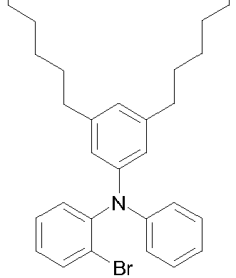
87% 3c 

64% 3d 

92% 3e 

59% 3f 

89% 3g 

95% 3h 

32% 3i 

84% 3j 
65% - Eine Lösung aus 89.0 g (187 mmol, 1.0 eq) des Amins 3a wird in 1 L getrocknetem THF gelöst und mit 75 ml n-BuLi (187 mmol, 1.0 eq, 2.5 M in Hexan) bei -78°C versetzt. Nach beendeter Zugabe wird das Reaktionsgemisch für eine Stunde bei dieser Temperatur gerührt und anschließend eine Lösung aus 63.2 g (187 mmol, 1.0 eq) 4a in 400 ml getrocknetem THF zugegeben. Das Reaktionsgemisch wird für weitere 30 Minuten bei -78°C gerührt und über Nacht auf Raumtemperatur erwärmt. Anschließend wird die Reaktion mit Wasser gequencht, die organische Phase nach Zugabe von etwas Diethylether abgetrennt und mit Wasser und ges. Kochsalzlösung gewaschen. Die organische Phase wird über Natriumsulfat getrocknet und das Lösungsmittelgemisch am Rotationsverdampfer entfernt. Das isolierte Zwischenprodukt wird in eine Mischung aus 100 ml konz. HCl und 1 L Essigsäure gegeben und für 2 h refluxiert. Das Reaktionsgemisch wird abgekühlt, mit Wasser verdünnt und mit Dichlormethan extrahiert. Die vereinten organischen Phasen werden mit ges. Natriumhydrogencarbonatlösung und Wasser gewaschen, anschließend über Natriumsulfat getrocknet und das Lösungsmittel im Vakuum entfernt. Der erhaltene Feststoff wird aus Toluol/Heptan umkristallisiert. Es werden 79.2 g (110 mmol, 59%) eines farblosen Feststoffs erhalten.
Analog werden hergestellt: Nr. Edukt 3 Edukt 4 Produkt 5 Ausbeute 5b 


41% 5c 


32% 5d 

22% 5e 


54% 5f 

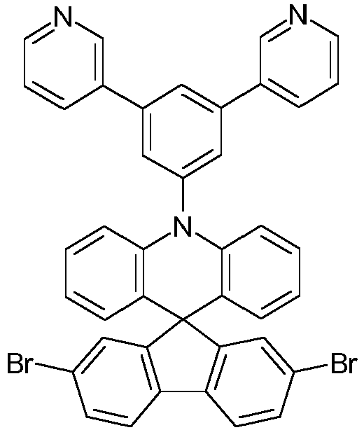
67% 5g 
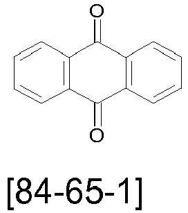

71% 5h 


78% 5i 


18% 5j 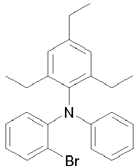

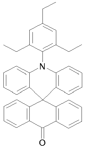
63% 5k 

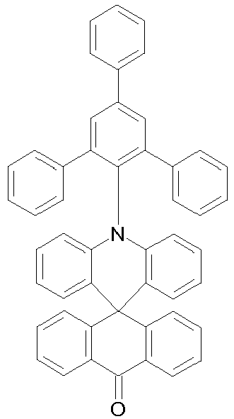
44% 5k 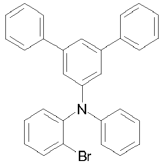

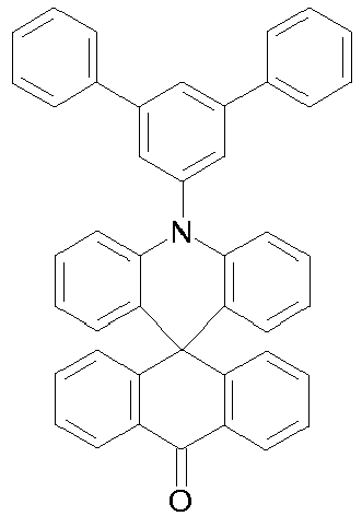
37% - Ein Gemisch aus 79.0 g (110 mmol, 1.0 eq) des Dibromids 5a und 24.6 g (275 mmol, 2.5 eq) Kupfer(I)-cyanid [544-92-3] in 1.2 L NMP werden bei 170°C für 24 h gerührt. Nach beendeter Reaktion wird die Lösung auf 2 N Natronlauge gegeben und mit Natriumhypochlorit versetzt. Die erhaltene Lösung wird für eine halbe Stunde gerührt und mit Toluol extrahiert. Die vereinten organischen Phasen werden mit Wasser gewaschen, über Natriumsulfat getrocknet und das Lösungsmittel am Rotationsverdampfer entfernt (Rohausbeute: 56.3 g, 92.4 mmol, 84%). Der erhaltene Feststoff wird aus Toluol/Heptan mehrfach umkristallisiert, bis eine Reinheit von >99.9% (HPLC) erreicht wird. Abschließend wird das Produkt mittels Sublimation aufgereinigt. Es werden 28.1 g (46.2 mmol, 42%) der hochreinen Zielverbindung erhalten.
Analog werden hergestellt: Nr. Edukt 5 Produkt Ausbeute 6b 
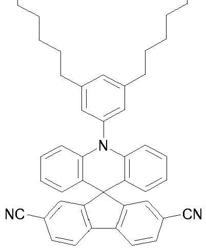
54% nicht sublimiert 6c 

47% nicht sublimiert 6d 

68% 6e 

33% nicht sublimiert 6f 

71% -

- Es werden 20 g (33 mol, 1.0 eq) des Edukts 5g in 500 ml DMF vorgelegt und langsam mit 12 g (68 mmol, 2.05 eq) N-Bromsuccinimid versetzt. Nach drei Stunden bei Raumtemperatur wird der ausgefallene Feststoff abgesaugt und mit Ethanol gewaschen. Es werden 24 g (31 mmol, 96%) eines beigen Feststoffs 7a erhalten.
- Es werden 24 g (31 mmol, 1.0 eq) des Dibromids 7a, 9.5 g (78 mmol, 2.5 eq) Phenylboronsäure und 26 g (124 mmol, 4.0 eq) Trikaliumphosphat vorgelegt und mit 375 ml Toluol, 150 ml Dioxan und 375 ml Wasser versetzt. Nachdem das Gemisch für 30 Minuten entgast wird, werden 70 mg (0.31 mmol, 0.01 eq) Palladium(II)-acetat und 570 mg (1.9 mmol, 0.06 eq) Tri-o-tolylphosphin zugegeben und über Nacht bei 85°C gerührt. Nach beendeter Reaktion werden die Phasen im Scheidetrichter getrennt, die organische Phase mit Toluol extrahiert und die vereinten organischen Phasen mit Wasser gewaschen. Die organische Phase wird anschließend über Natriumsulfat getrocknet und das Lösungsmittel am Rotationsverdampfer entfernt. Es werden 22 g (29 mmol, 93%) eines farblosen Feststoffs erhalten, der mehrfach aus Toluol/Heptan umkristallisiert wird, bis eine HPLC-Reinheit von >99.9% erreicht wird. Abschließend wird das erhaltene Zielprodukt mittels Sublimation aufgereinigt. Es werden 11.5 g (15 mmol, 48%) der hochreinen Verbindung 8a erhalten.
-

- 30 g (50 mmol, 1.0 eq) des nicht-aufgereinigten Rohproduktes 5g werden unter Schutzgas zusammen mit 16.5 g (250 mmol, 5.0 eq) Malonsäuredinitril in 1.5 L Dichlormethan gelöst. Anschließend werden langsam 250 ml (250 mmol, 5.0 eq) Titan(IV)-chlorid als 1 M Lösung in Dichlormethan, gefolgt von 20 ml (500 mmol, 10 eq) getrocknetem Pyridin zugegeben. Das Reaktionsgemisch wird für 24 Stunden unter Rückfluss gekocht und erneut dieselben Mengen Malonsäuredinitril, Titan(IV)-chlorid und getrocknetes Pyridin zugegeben. Nachdem erneut für 24 Stunden unter Rückfluss gekocht wird, werden 500 ml Dichlormethan zugegeben und die organische Phase sukzessive mit 10% HCl und 5% NaOH gewaschen. Die organische Phase wird über Natriumsulfat getrocknet und das Lösungsmittel am Rotationsverdampfer entfernt. Der erhaltene Feststoff 11.7 g (18 mmol, 36%) wird mit Toluol/Heptan umkristallisiert bis eine HPLC-Reinheit von >99.9% erreicht wird, abschließend wird eine Sublimation durchgeführt. Es werden 3.6 g (5.5 mmol, 11%) des hochreinen Produkts 9a erhalten.
Analog werden hergestellt: Nr. Edukt 8 Produkt 9 Ausbeute 9b 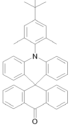

14% 9c 

9% 9d 

24% 9e 

21% 9f 

13% -

- Die Synthese wird entsprechend der Vorschrift für Verbindung 3a durchgeführt.
Analog werden erhalten: Nr. Edukt 10 Edukt 11 Produkt 12 Ausbeute 12a 


64% 12b 


57% 12c 


61% 12d 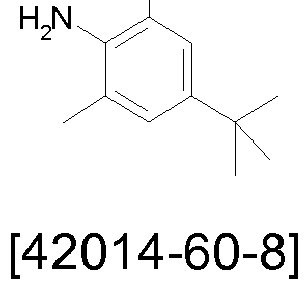


48% 12e 


56% 12f 


67% 12g 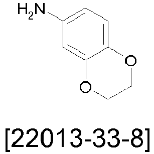
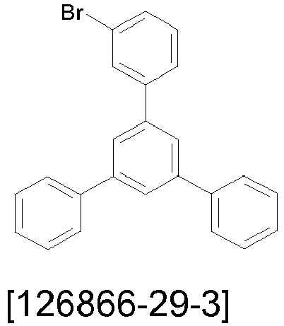

31% 12h 


45% - Es werden 5.7 g (11 mmol, 1.0 eq) 2,7-Dibromo-2',7'-dicyano-9,9'spirobifluoren und 17 g (33 mmol, 3.0 eq) des Amins 12a in 100 ml trockenem Toluol vorgelegt und für 30 Minuten mit Argon entgast. Anschließend werden 62 mg (0.28mmol, 0.025 eq) Palladium(II)-acetat und 0.55 ml (0.55 mmol, 0.05 eq) tri-tert-Butylphosphin (1 M in Toluol) zugegeben und der Ansatz über Nacht unter Rückfluss erhitzt. Nach beendeter Reaktion wird Wasser zugegeben, die organische Phase abgetrennt und erneut mit Wasser gewaschen. Anschließend werden die vereinten wässrigen Phasen mit Toluol extrahiert. Die organischen Phasen werden über Natriumsulfat getrocknet und das Lösungsmittel am Rotationsverdampfer entfernt. Es werden 11.5 g (8.3 mmol, 75%) eines beigen Feststoffs erhalten, welcher durch Umkristallisation mit Heptan/Toluol weiter aufgereinigt wird bis eine HPLC-Reinheit >99.9% erreicht wird. Abschließend wird der Feststoff für fünf Stunden unter Vakuum bei 300°C getempert. Es werden 8.9 g (6.4 mmol, 58%) der Zielverbindung 14a erhalten.
-
Nr. Edukt 12 Edukt 13 Produkt 14 Ausbeute 14b 

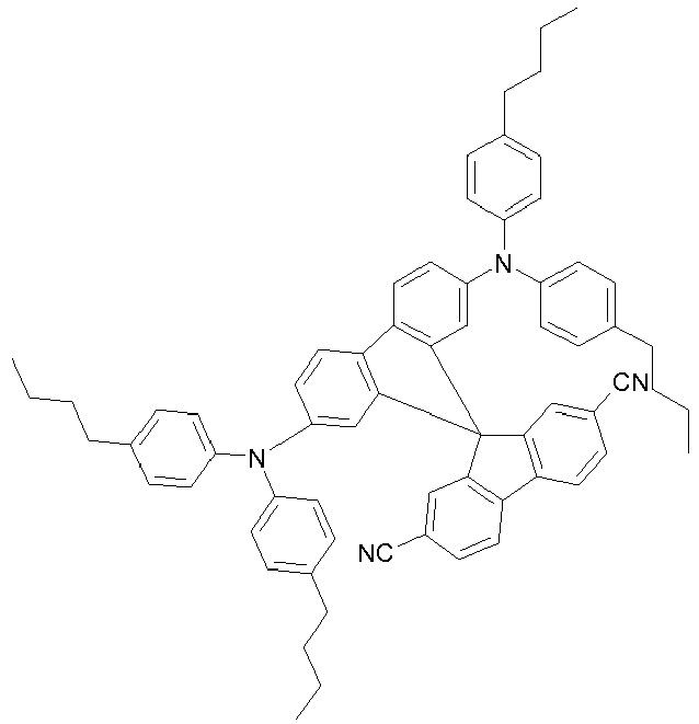
58% 14c 


31% 14d 


46% 14e 

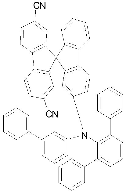
67% 14f 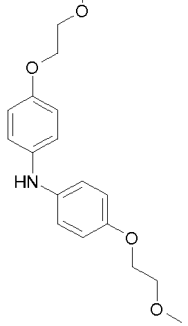

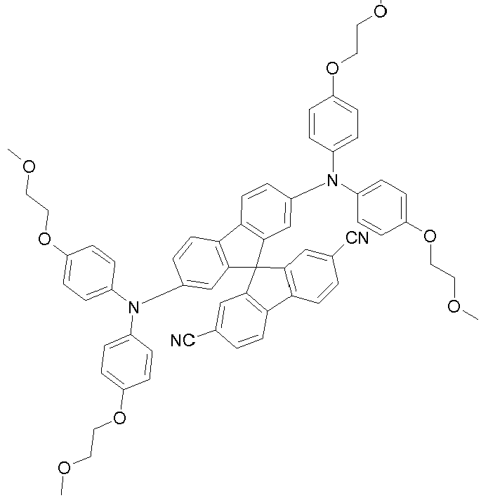
18% 14g 


25% 14h 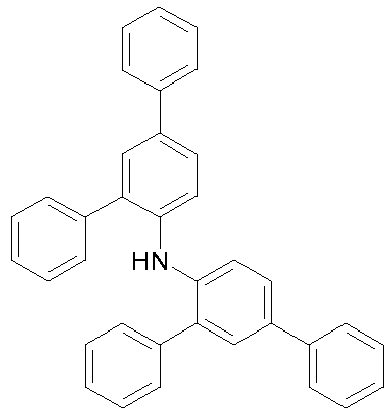


49% 14i 

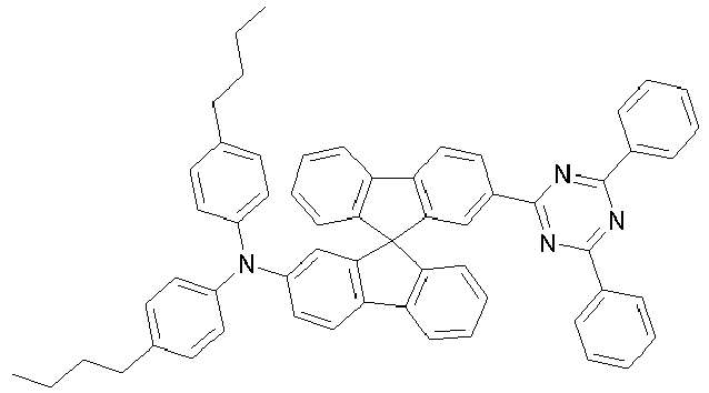
69% -
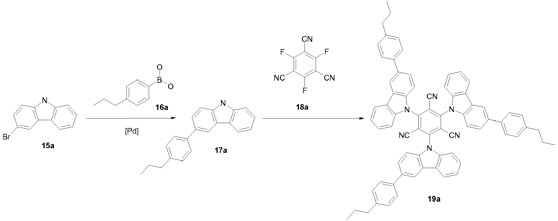
- 25 g (100 mmol, 1.0 eq) 3-Brom-9H-carbazol werden zusammen mit 20 g (120 mmol, 1.2 eq) 4-Propylphenylboronsäure [134150-01-9] und 23 g Trikaliumphosphat (106 mmol, 1.06 eq) in je 350 ml Toluol, Dioxan und Wasser vorgelegt und für 30 Minuten entgast. Anschließend werden 450 mg (2.0 mmol, 0.02 eq) Palladium(II)-acetat und 1.5 g (5.0 mmol, 0.05 eq) Tri-o-tolylphosphin zugegeben und das Reaktionsgemisch über Nacht auf Rückfluss erhitzt. Nach beendeter Reaktion wird die organische Phase abgetrennt und mit Wasser gewaschen. Die wässrige Phase wird mit Toluol extrahiert und die vereinten organischen Phasen über Natriumsulfat getrocknet. Der erhaltene Feststoff wird mit Ethanol ausgewaschen. Nach Trocknung werden 26 g (91 mmol, 91%) eines leicht beigen Feststoffs 17a erhalten.
Analog werden hergestellt: Nr. Edukt 15 Edukt 16 Produkt 17 Ausbeute 17b 


88% 17c 


64% - Eine gut gerührte Suspension von 3.6 g (91 mmol, 4.0 eq) Natriumhydrid, 60 Gew.-% ige Dispersion in Mineralöl, in 500 ml THF wird unter Eiskühlung bei ca. +10°C portionsweise mit 26 g (91 mmol, 4.0 eq) der Verbindung 17a versetzt - Vorsicht Wasserstoffentwicklung! Schäumen! Nach beendeter Zugabe wird die Mischung 30 Minuten nachgerührt und dann portionsweise unter Eiskühlung so mit 6.6 g (23 mmol, 1.0 eq) 1,3,5-Tricyano-2,4,6-trifluorbenzol [363897-9] versetzt, dass die Temperatur +20°C nicht übersteigt. Nach beendeter Zugabe rührt man 2 h bei +10°C nach, entfernt dann das Kältebad, lässt auf 20-25°C erwärmen, rührt 2 h nach und erwärmt dann noch 12 h auf 40°C. Nach Abkühlen auf Raumtemperatur wird die Reaktion durch Zutropfen von 30 ml Methanol beendet und die Reaktionsmischung im Vakuum fast bis zur Trockene eingeengt. Der Rückstand wird zweimal mit je 225 ml eines Gemischs aus 175 ml Methanol und 50 ml Wasser und dann einmal mit 100 ml Methanol heiß ausgerührt. Die Reinigung erfolgt durch mehrfache Umkristallisation aus Heptan/Toluol bis eine HPLC-Reinehit >99.9% erreicht wird. Es werden 4.8 g (4.8 mmol, 21%) eines farblosen Feststoffs 18a erhalten.
- Eine gut gerührte Suspension von 3.6 g (91 mmol, 4.0 eq) des Carbazols 17a, 6.6 g (23 mmol, 1.0 eq) 1,3,5-Tricyano-2,4,6-trifluorbenzol, 24.4 g (115 mmol, 5.0 eq) Trikaliumphosphat, wasserfrei und 200 g Glaskugeln werden in 500 ml Dimethylacetamid 16 h bei 160 °C gerührt. Nach Erkalten gibt man 1000 ml Wasser zu, saugt vom ausgefallenen Feststoff ab, wäscht diesen zweimal mit je 300 ml Wasser, zweimal mit je 200 ml Methanol und trocknet dann im Vakuum. Die weitere Reinigung erfolgt analog zu der in Variante A beschriebenen Aufreinigung. Ausbeute: 7.8 g (7.8 mmol, 34%), Reinheit: 99.9 % n. HPLC.
-
Nr. Edukt 17 Edukt 18 Produkt 19 Ausbeute 19b 


A 41% 19c 
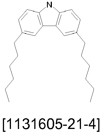

A 24% 19d 

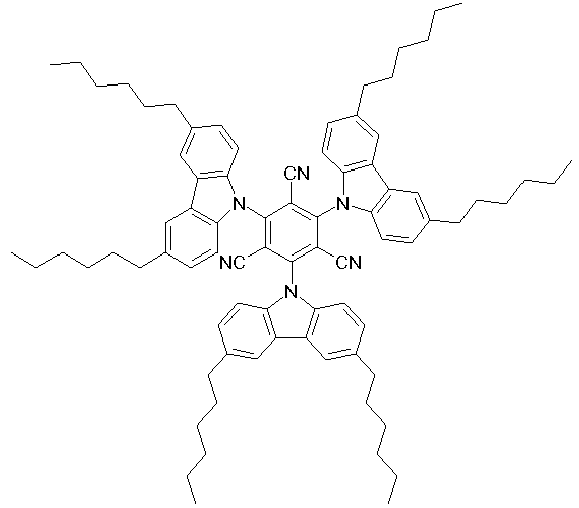
B 22% 19e 
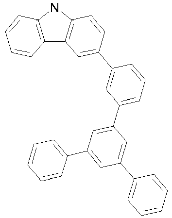

A 37% 19f 


B 14% A und B in der Spalte Ausbeute beziehen sich auf die für die jeweiligen Verbindungen durchgeführten Varianten. - Für eine gute Verarbeitbarkeit aus Lösung ist eine hohe Löslichkeit in gängigen Lösungsmitteln von entscheidender Bedeutung. Gängige mittels Spin-coating aufgebrachte Lösungen in Toluol enthalten eine Mischung der OLED-aktiven Substanzen mit einer Gesamtkonzentration von ca. 20 mg/ml. Bei der Verwendung von höhersiedenden Lösungsmitteln wie z.B. Mesitylen müssen sogar noch höhere Konzentrationen verwendet werden, um gleiche Schichtdicken zu erreichen. Hat eine Einzelsubstanz nur eine Löslichkeit von 2 mg/ml in Toluol, so können nur Mischungen mit maximal 10% dieser Komponente aus Lösung verarbeitet werden; aus höhersiedenden Lösungsmitteln sogar noch geringere Materialanteile. Eine Löslichkeit von 5 mg/ml erlaubt dagegen die Prozessierung von Mischungen mit bis zu 25% dieser Komponente, eine Löslichkeit von 10 mg/ml entsprechend bis zu 50%.
- Die Löslichkeiten ausgewählter Materialien finden sich in Tabelle 1.
Tabelle 1: Löslichkeiten ausgewählter Materialien Bsp. Material Löslichkeit in Toluol > 2mg/ml Löslichkeit in Toluol > 5mg/ml Löslichkeit in Toluol > 10mg/ml V1-1 
ja Nein Nein CAS 1416881-52-1 V1-2 
Nein Nein Nein CAS 1206626-92-7 V1-3 
ja Nein Nein CAS 1418575-73-1 E1-1 6a ja ja Nein E1-2 9a ja ja Ja E1-3 9e ja ja Nein E1-4 19d ja ja Ja - Die Materialien, die für folgenden Beispiele benötigt werden, sind in Tabelle 2 dargestellt. Die zugehörigen HOMO und LUMO Energieniveaus sowie S1 und T1 sind in Tabelle 3 angegeben.
- Die Herstellung vollständig lösungsbasierter OLEDs ist in der Literatur bereits vielfach beschrieben, z.B. in
WO 2004/037887 . Die Herstellung vakuumbasierter OLEDs ist ebenfalls vielfach vorbeschrieben, u.a. inWO 2004/058911 . - In den im Folgenden diskutierten Beispielen wurden lösungsbasiert und vakuumbasiert aufgebrachte Schichten innerhalb einer OLED kombiniert, so dass die Prozessierung bis einschließlich zur Emissionsschicht aus Lösung und in den darauffolgenden Schichten (Lochblockierschicht und Elektronentransportschicht) aus dem Vakuum erfolgte. Die vorbeschriebenen allgemeinen Verfahren werden dafür wie folgt auf die hier beschriebenen Gegebenheiten (Schichtdickenvariation, Materialien) angepasst und kombiniert:
Der generelle Aufbau ist wie folgt: Substrat / ITO (50 nm) / Lochinjektionsschicht(HIL) / Lochtransportschicht (HTL) / Emissionsschicht (EML) / Lochblockierschicht (HBL) / Elektronentransportschicht (ETL) / Kathode (Aluminium, 100 nm) - Gereinigte Glasplättchen (Reinigung in Miele Laborspülmaschine, Reiniger Merck Extran), die mit strukturiertem ITO (Indium Zinn Oxid) der Dicke 50 nm beschichtet sind, werden 20 min. mit einem UV-Ozon Plasma behandelt und anschließend zur besseren Prozessierung mit PEDOT:PSS beschichtet (Poly(3,4-ethylendioxy-2,5-thiophen) : Polystyrolsulfonat, bezogen von Heraeus Precious Metals GmbH & Co. KG, Deutschland). PEDOT:PSS wird an Luft aus Wasser aufgeschleudert und nachfolgend an Luft bei 180°C für 10 Minuten ausgeheizt, um Restwasser zu entfernen. Auf diese Substrate wird eine vernetzbare Lochtransportschicht aufgebracht. Sie besteht aus einem Polymer der folgenden Strukturformel,

WO 2010/097155 synthetisiert wurde. Das Material wird in Toluol gelöst. Der Feststoffgehalt der Lösung liegt bei 5 g/l. Die Schichten werden in einer Inertgasatmosphäre, im vorliegenden Fall Argon, aufgeschleudert und 60 Minuten bei 180°C ausgeheizt.
Im Anschluss wird die Emissionsschicht aufgebracht. Diese setzt sich immer aus mindestens einem Matrixmaterial (Hostmaterial, Wirtsmaterial) und einem emittierenden Dotierstoff (Dotand, Emitter) zusammen. Eine Angabe wie IC2(60%):WB1 (30%):6a(10%) bedeutet, dass das Material IC2 in einem Gewichtsanteil von 60%, WB1 in einem Gewichtsanteil von 30% und 6a in einem Gewichtsanteil von 10% in der Lösung vorliegt, aus der die Emissionsschicht hergestellt wird. Eine entsprechende Feststoffmischung für die Emissionsschicht wird in Toluol gelöst. Der Feststoffgehalt liegt bei 18 g/l. Die Emissionsschicht wird in einer Stickstoffatmosphäre aufgeschleudert und 10 Minuten bei 180°C in einer Stickstoffatmosphäre ausgeheizt. - Im Anschluss werden die Proben ohne Kontakt zu Luft in eine Vakuumkammer eingebracht und weitere Schichten durch thermisches Verdampfen aufgebracht. Besteht eine solche Schicht aus mehreren Materialien, gilt für die Mischungsverhältnisse der Einzelkomponenten die weiter oben beschriebene Nomenklatur, wobei die Gewichtsanteile durch Volumenanteile zu ersetzen sind.
- Zur Charakterisierung der OLEDs werden Strom-Spannungs-Leuchtdichtekennlinien gemessen. Die Leuchtdichte wird mit einer kalibrierten Photodiode bestimmt. Weiterhin wird das Elektrolumineszenzspektrum bei einer Leuchtdichte von 1000 cd/m2 gemessen. Hieraus wird unter Annahme einer lambertschen Abstrahlcharakteristik die externe Quanteneffizienz (EQE, gemessen in Prozent) berechnet.
- Für die Emissionsschicht wird eine Feststoffmischung IC2(60%):WB1 (30%):20a(10%) verwendet. Hieraus wird wie oben beschrieben eine 60 nm dicke Emissionsschicht hergestellt. Anschließend wird eine 10 nm dicke Schicht des Materials ST1 und danach eine 40 nm dicke Schicht ST1 (50%):LiQ(50%) durch thermisches Verdampfen im Vakuum aufgebracht. Anschließend wird als Kathode eine 100 nm dicke Aluminiumschicht durch Verdampfen im Vakuum aufgebracht.
- Die OLEDs zeigen grüne Emission, 14.2% EQE bei 1000 cd/m2 und benötigen für diese Leuchtdichte 7.4 V Spannung.
- Die OLED entspricht dem Beispiel V2-1, mit dem Unterschied, dass statt der Mischung IC2(60%):WB1 (30%):20a(10%) die Mischung IC2(60%):WB1 (25%):19d(15%) verwendet wird.
- Die OLEDs zeigen grüne Emission, 14.6% EQE bei 1000 cd/m2 und benötigen für diese Leuchtdichte 7.3 V Spannung.
- Die OLED entspricht dem Beispiel E2-1, mit dem Unterschied, dass die Mischung IC2(60%):WB1(20%):19d(20%) verwendet wird.
- Die OLEDs zeigen grüne Emission, 14.9% EQE bei 1000 cd/m2 und benötigen für diese Leuchtdichte 8.1 V Spannung.
- Die OLED entspricht dem Beispiel E2-1, mit dem Unterschied, dass die Mischung IC2(60%):WB1 (25%):9a(15%) verwendet wird.
- Die OLEDs zeigen grüne Emission, 12.8% EQE bei 1000 cd/m2 und benötigen für diese Leuchtdichte 7.5 V Spannung.
- Die OLED entspricht dem Beispiel E2-1, mit dem Unterschied, dass die Mischung IC2(60%):WB1 (20%):9a(20%) verwendet wird.
- Die OLEDs zeigen grüne Emission, 13.2% EQE bei 1000 cd/m2 und benötigen für diese Leuchtdichte 7.7 V Spannung.
- Die OLED entspricht dem Beispiel E2-1, mit dem Unterschied, dass die Mischung IC2(60%):WB1 (25%):9e(15%) verwendet wird.
- Die OLEDs zeigen grüne Emission, 12.5% EQE bei 1000 cd/m2 und benötigen für diese Leuchtdichte 7.3 V Spannung.
- Die OLED entspricht dem Beispiel E2-1, mit dem Unterschied, dass die Mischung IC2(60%):WB1 (20%):9e(20%) verwendet wird.
- Die OLEDs zeigen grüne Emission, 13.0% EQE bei 1000 cd/m2 und benötigen für diese Leuchtdichte 7.4 V Spannung.
- Die OLED entspricht dem Beispiel E2-1, mit dem Unterschied, dass die Mischung IC2(60%):WB1 (20%):6a(20%) verwendet wird.
- Die OLEDs zeigen grünlich blaue Emission, 10.5% EQE bei 1000 cd/m2 und benötigen für diese Leuchtdichte 7.2 V Spannung.
- In den erfindungsgemäßen Beispielen zeigt sich, dass die Verwendung höherer Konzentrationen des Dotierstoffs vorteilhaft insbesondere für die Effizienz der erzeugten Bauteile ist. Diese höheren Konzentrationen können nur bei ausreichender Löslichkeit des Dotierstoffs erreicht werden, die durch Verwendung der erfindungsgemäßen Materialien gegeben ist. Insgesamt können mit den erfindungsgemäßen Materialien effiziente lösungsprozessierte OLEDs ohne die Verwendung von Übergangsmetallkomplexen erzielt werden.
Tabelle 2: Strukturformeln der Materialien für die OLEDs 
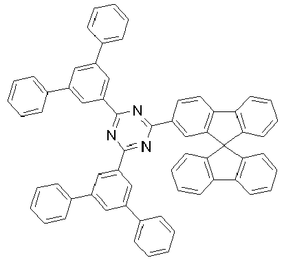
LiQ ST1 

WB1 IC2 Tabelle 3: HOMO, LUMO, T1, S1 der relevanten Materialien Material Methode HOMO LUMO S1 T1 (eV) (eV) (eV) (eV) IC2 org. -5.78 -2.84 3.04 2.69 WB1 org. -6.16 -2.24 3.38 2.95 ST1 org. -6.03 -2.82 3.32 2.68 LiQ M-org. -5.17 -2.39 2.85 2.13 6a org. -5.60 -3.01 2.47 2.46 9a org. -5.58 -3.32 2.18 2.17 9e org. -5.57 -3.29 2.20 2.19 19d org. -5.89 -3.66 2.11 2.10
Claims (14)
- Organische lumineszierende TADF-Verbindung der Formel (1), die keine Metalle enthält, die einen Abstand zwischen dem ersten angeregten Triplett-Zustand (T1) und dem ersten angeregten Singulett-Zustand (S1) von kleiner oder gleich 0.15 eV aufweist,
 m ist eine ganze Zahl ausgewählt aus 1, 2, 3, 4 oder 5;n ist eine ganze Zahl ausgewählt aus 1, 2, 3, 4 oder 5;p ist eine ganze Zahl, die größer oder gleich 1 ist; bevorzugt ist p eine ganze Zahl von 1 bis 12, ganz bevorzugt eine ganze Zahl von 1 bis 10, ganz besonders bevorzugt eine ganze Zahl von 1 bis 8, insbesondere bevorzugt eine ganze Zahl von 1 bis 6 und weiterhin bevorzugt eine ganze Zahl von 1 bis 4;A ist eine Akzeptorgruppe, die eine Elektronenakzeptorgruppe darstellt, wobei die Elektronenakzeptorgruppe eine Cyanogruppe, Nitrilgruppe, Oxogruppe, CF3 oder elektronenarme Heteroarylgruppe wie Pyrimidine, Pyrazine, Triazine enthält, die mit einem oder mehreren Resten R1, die bei jedem Auftreten gleich oder verscheiden sein können, substituiert sein kann;D ist eine Donorgruppe, die eine Elektronendonorgruppe darstellt, wobei die Elektronendonorgruppe eine Diarylaminogruppe, Diarylheteroarylaminogruppe, Carbazolgruppe, Indenocarbazolgruppe oder Indolocarbazolgruppe enthält, die mit einem oder mehreren Resten R1, die bei jedem Auftreten gleich oder verscheiden sein können, substituiert sein kann;LG ist eine löslichkeitsvermittelnde Gruppe, die an A, D und/oder V gebunden sein kann, bevorzugt ist sie an die Gruppen A und/oder D gebunden und ganz bevorzugt ist sie an die Gruppe D gebunden, wobei die Gruppe LG ausgewählt ist auswobei die gestrichelte Bindung die Bindung von LG an A, D oder V angibt.einer geradkettigen Alkyl- oder Alkoxygruppe mit 3 bis 15 C-Atomen;einer verzweigten oder cyclischen Alkyl- oder Alkoxygruppe mit 3 bis 40 C-Atomen, bevorzugt mit 3 bis 30 C-Atomen, ganz bevorzugt mit 3 bis 20 C-Atomen, ganz besonders bevorzugt mit 3 bis 15 C-Atomen und insbesondere bevorzugt mit 3 bis 10 C-Atomen;einem aromatischen oder heteroaromatischen Ringsystem mit 3 oder mehr aromatischen oder heteroaromatischen Ringen, die mir einem oder mehreren, gleichen oder verschiedenen Resten R1 substituiert sein können;einem aromatischen oder heteroaromatischen Ringsystem mit 1 oder 2 aromatischen oder heteroaromatischen Ringen, die mit einem oder mehreren, gleichen oder verschiedenen Resten R1, die ungleich H sind, in ortho Position substituiert sind, wobei die Ringe mit weiteren, gleichen oder verschiedenen Resten R1 substituiert sein können;einer Gruppe der Formel (LG-1)
 Ar1, Ar2 sind jeweils unabhängig voneinander eine Aryl- oder Heteroarylgruppe, welche mit einem oder mehreren Resten R1 substituiert sein kann,X ist jeweils unabhängig voneinander N oder CR2, wobei maximal eine der drei Gruppen X ein N sein darf; bevorzugt sind alle drei X gleich CR2 und ganz bevorzugt ist X gleich CH,R2 ist jeweils unabhängig voneinander Wasserstoff, eine geradkettige Alkyl-, Alkoxy- oder Thioalkoxygruppe mit 1 bis 40 C-Atomen oder eine verzweigte oder cyclische Alkyl-, Alkoxy- oder Thioalkoxygruppe mit 3 bis 40 C-Atomen oder eine Silylgruppe oder eine substituierte Ketogruppe mit 1 bis 40 C-Atomen, eine Alkoxy-carbonylgruppe mit 2 bis 40 C-Atomen, eine Aryloxycarbonylgruppe mit 7 bis 40 C-Atomen, eine vernetzbare Gruppe oder ein substituiertes oder unsubstituiertes aromatisches oder heteroaromatisches Ringsystem mit 5 bis 60 Ringatomen, oder eine Aryloxy- oder Heteroaryloxygruppe mit 5 bis 60 Ringatomen, oder eine Kombination dieser Systeme, wobei zwei oder mehrere der Gruppen R2 ein mono- oder polycyclisches, aliphatisches oder aromatisches Ringsystem miteinander bilden können;I ist 0, 1, 2, 3 oder 4;V ist eine beliebige organische Brücke zwischen den Gruppen A und D oder eine Einfachbindung, wobei, wenn V eine Einfachbindung darstellt, entweder m oder n gleich 1 ist, und
wenn V eine organische Brücke darstellt, dann ist die Brücke V aus den Formeln (V-1) bis (V-7) ausgewählt,

 R1 ist gleich oder verscheiden bei jedem Auftreten Wasserstoff, eine geradkettige Alkyl-, Alkoxy- oder Thioalkoxygruppe mit 1 bis 40 C-Atomen oder eine verzweigte oder cyclische Alkyl-, Alkoxy- oder Thioalkoxygruppe mit 3 bis 40 C-Atomen ist oder eine Silylgruppe oder eine substituierte Ketogruppe mit 1 bis 40 C-Atomen, eine Alkoxy-carbonylgruppe mit 2 bis 40 C-Atomen, eine Aryloxycarbonyl-gruppe mit 7 bis 40 C-Atomen, eine vernetzbare Gruppe oder ein substituiertes oder unsubstituiertes aromatisches oder heteroaromatisches Ringsystem mit 5 bis 60 Ringatomen, oder eine Aryloxy- oder Heteroaryloxygruppe mit 5 bis 60 Ringatomen, oder eine Kombination dieser Systeme ist, wobei zwei oder mehrere der Gruppen R1 miteinander ein mono- oder polycyclisches, aliphatisches oder aromatisches Ringsystem bilden können, wobei bevorzugt ist, wenn zwei oder mehrere der Gruppen R1 miteinander kein mono- oder polycyclisches, aliphatisches oder aromatisches Ringsystem bilden können.
 - Verbindung gemäß Anspruch 1, dadurch gekennzeichnet, dass die TADF-Verbindung eine organische Verbindung mit einem Molekulargewicht von kleiner oder gleich 5000 g/mol, ganz bevorzugt von kleiner oder gleich 4000 g/mol, besonders bevorzugt von kleiner oder gleich 3000 g/mol, ganz besonders bevorzugt von kleiner oder gleich 2000 g/mol, insbesondere bevorzugt von kleiner oder gleich 1500 g/mol und noch bevorzugter von kleiner oder gleich 1000 g/mol ist.
- Verbindung gemäß Anspruch 1 oder 2, dadurch gekennzeichnet, dass die Gruppe LG ausgewählt ist aus den folgenden Gruppen, wobei die Gruppen weiter mit einem oder mehreren gleichen oder verschiedenen Resten R1 substituiert sein können.


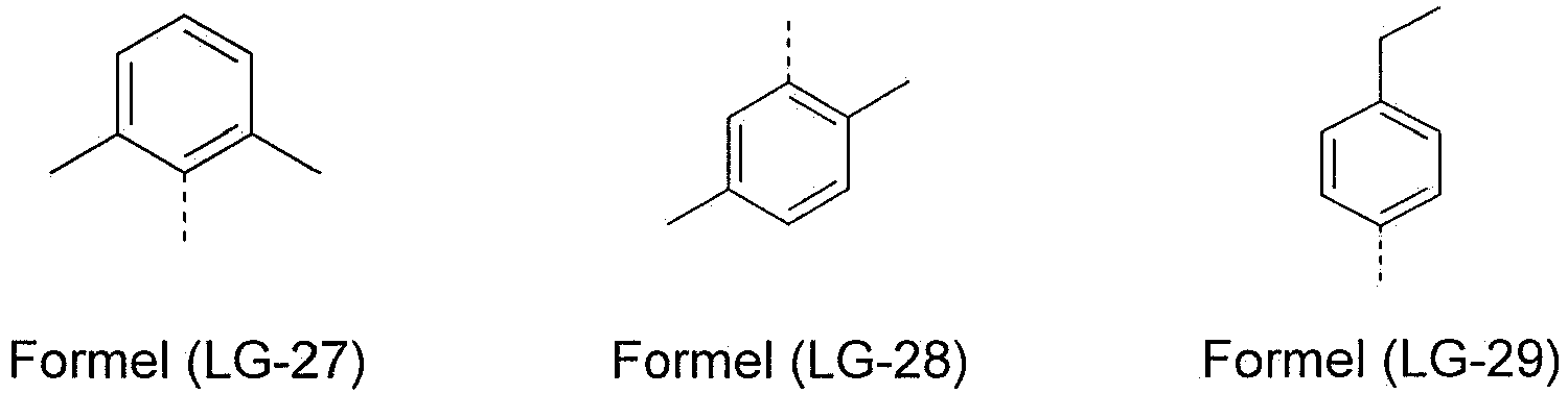


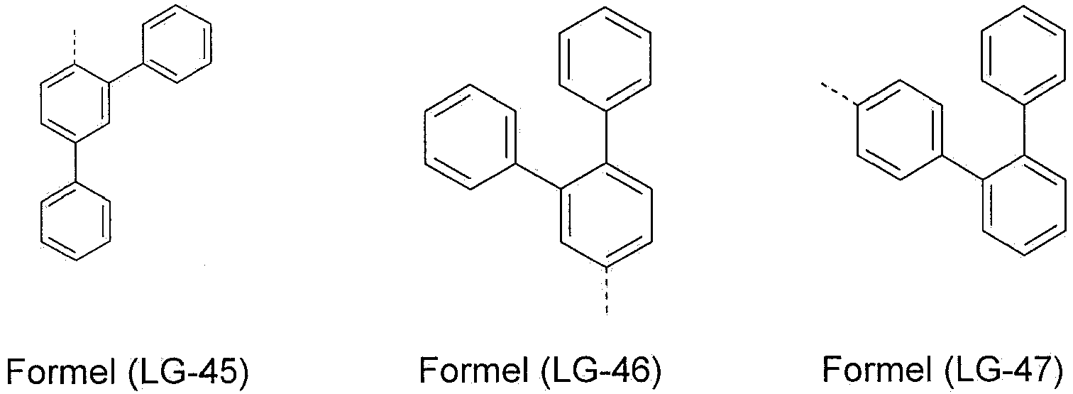
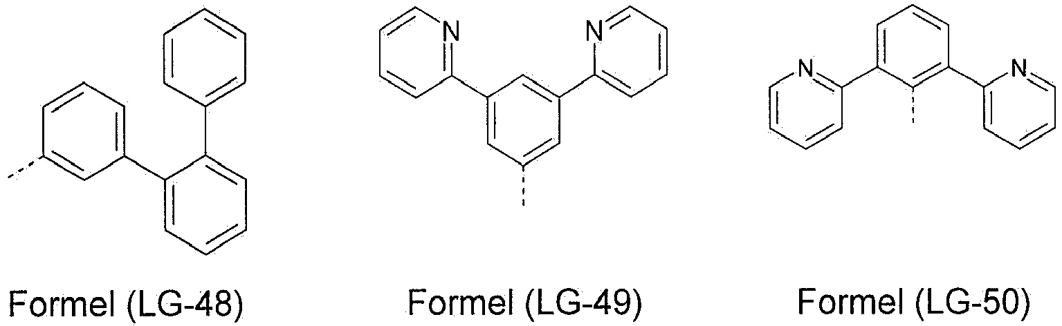


- Verbindung gemäß einem oder mehreren der Ansprüche 1 bis 3, dadurch gekennzeichnet, dass die Verbindung wenigstens 3, bevorzugt wenigstens 4, ganz bevorzugt wenigstens 5 und insbesondere wenigstens 6 aromatische Ringe enthält.
- Zusammensetzung enthaltend eine oder mehrere der Verbindungen gemäß einem oder mehreren der Ansprüche 1 bis 4 sowie ein oder mehrere funktionelle Materialien ausgewählt aus der Gruppe der elektronleitenden Materialien (ETM), elektroninjizierenden Materialien (EIM), elektronenblockierenden Materialien (EBM), lochleitenden Materialien (HTM), lochinjizierenden Materialien (HIM), lochblockierenden Materialien (HBM), fluoreszierenden Emittern, phosphoreszierenden Emittern, Matrixmaterialien und anorganischen Nanoteilchen, wobei Matrixmaterialien besonders bevorzugt sind
- Zusammensetzung gemäß Anspruch 5, dadurch gekennzeichnet, dass die Zusammensetzung zwei Matrixmaterialien enthält.
- Formulierung enthaltend wenigstens eine Verbindung gemäß einem oder mehreren der Ansprüche 1 bis 4 oder eine Zusammensetzung gemäß Anspruch 5 oder 6 sowie wenigstens ein Lösungsmittel.
- Verwendung der Formulierung gemäß Anspruch 7 zur Herstellung einer oder mehrere Schichten einer organischen elektronischen Vorrichtung aus Lösung.
- Verfahren zur Herstellung einer organischen elektronischen Vorrichtung, dadurch gekennzeichnet, dass wenigstens eine Schicht der elektronischen Vorrichtung mit Hilfe der Formulierung gemäß Anspruch 7 aus Lösung hergestellt wird.
- Verwendung wenigstens einer Verbindung gemäß einem oder mehreren der Ansprüche 1 bis 4 oder wenigstens einer Zusammensetzung gemäß Anspruch 5 oder 6 in einer organischen elektronischen Vorrichtung, bevorzugt in einer organischen Elektrolumineszenzvorrichtung, ganz bevorzugt in einer organischen lichtemittierenden Diode (OLED) oder organischen lichtemittierenden elektrochemischen Zelle (OLEC, LEEC, LEC), ganz besonders bevorzugt in einer OLED und insbesondere bevorzugt in der Emissionsschicht (EML) einer OLED.
- Organische elektronische Vorrichtung enthaltend wenigstens eine Verbindung gemäß einem oder mehreren der Ansprüche 1 bis 4 oder wenigstens eine Zusammensetzung gemäß Anspruch 5 oder 6.
- Vorrichtung gemäß Anspruch 11, dadurch gekennzeichnet, dass sie ausgewählt ist aus organischen integrierten Schaltungen (OICs), organischen Feld-Effekt-Transistoren (OFETs), organischen Dünnfilmtransistoren (OTFTs), organischen Elektrolumineszenzvorrichtungen, organischen Solarzellen (OSCs), organischen optischen Detektoren, organischen Photorezeptoren, bevorzugt eine organische Elektroluminesszenzvorrichtung.
- Vorrichtung gemäß Anspruch 11 oder 12, dadurch gekennzeichnet, dass die Vorrichtung eine organische Elektrolumineszenzvorrichtung ist, die ausgewählt ist ausder Gruppe bestehend aus den organischen lichtemittierenden Transistoren (OLETs), organischen Feld-Quench-Devices (OFQDs), organischen lichtemittierenden elektrochemischen Zellen (OLECs, LECs, LEECs), organischen Laserdioden (O-Laser) und organischen lichtemittierenden Dioden (OLEDs), bevorzugt OLECs und OLEDs, ganz bevorzugt OLEDs.
- Vorrichtung gemäß einem oder mehreren der Ansprüche 11 bis 13, dadurch gekennzeichnet, dass es sich bei der Vorrichtung um eine organische Elektrolumineszenzvorrichtung handelt, die wenigstens eine Verbindung gemäß einem oder mehreren der Ansprüche 1 bis 4 oder wenigstens eine Zusammensetzung gemäß Anspruch 5 oder 6 in der Emissionsschicht enthält.
Applications Claiming Priority (2)
| Application Number | Priority Date | Filing Date | Title |
|---|---|---|---|
| EP14004201 | 2014-12-12 | ||
| PCT/EP2015/002311 WO2016091353A1 (de) | 2014-12-12 | 2015-11-18 | Organische verbindungen mit löslichen gruppen |
Publications (2)
| Publication Number | Publication Date |
|---|---|
| EP3230403A1 EP3230403A1 (de) | 2017-10-18 |
| EP3230403B1 true EP3230403B1 (de) | 2019-10-09 |
Family
ID=52100979
Family Applications (1)
| Application Number | Title | Priority Date | Filing Date |
|---|---|---|---|
| EP15805389.2A Active EP3230403B1 (de) | 2014-12-12 | 2015-11-18 | Organische verbindungen mit löslichen gruppen |
Country Status (7)
| Country | Link |
|---|---|
| US (1) | US10683453B2 (de) |
| EP (1) | EP3230403B1 (de) |
| JP (1) | JP2018501354A (de) |
| KR (1) | KR102493553B1 (de) |
| CN (2) | CN107001334A (de) |
| TW (1) | TWI694065B (de) |
| WO (1) | WO2016091353A1 (de) |
Families Citing this family (19)
| Publication number | Priority date | Publication date | Assignee | Title |
|---|---|---|---|---|
| GB201513037D0 (en) | 2015-07-23 | 2015-09-09 | Merck Patent Gmbh | Phenyl-derived compound for use in organic electronic devices |
| TWI732946B (zh) * | 2016-09-29 | 2021-07-11 | 日商住友化學股份有限公司 | 發光元件及對於該發光元件之製造為有用之組成物 |
| US11424410B2 (en) * | 2016-09-29 | 2022-08-23 | Sumitomo Chemical Company, Limited | Light emitting device |
| WO2018062277A1 (ja) * | 2016-09-29 | 2018-04-05 | 住友化学株式会社 | 発光素子 |
| CN110612466B (zh) * | 2017-06-02 | 2021-10-01 | 东丽株式会社 | 颜色转换片、包含其的光源单元、显示器及照明装置 |
| CN107325076B (zh) * | 2017-06-29 | 2019-09-27 | 上海天马有机发光显示技术有限公司 | 一种化合物及其发光器件和显示装置 |
| DE102017122886A1 (de) * | 2017-10-02 | 2019-04-04 | Aixtron Se | Verfahren zur Herstellung einer leuchtenden Pixelanordnung |
| CN111655674B (zh) | 2018-01-29 | 2024-01-23 | 出光兴产株式会社 | 化合物和使用该化合物的有机电致发光元件 |
| CN109666021A (zh) * | 2018-07-27 | 2019-04-23 | 华南理工大学 | 含羰基螺式给体的有机发光小分子材料及其制备方法和应用 |
| EP3975279B1 (de) * | 2018-10-15 | 2024-03-13 | Samsung Display Co., Ltd. | Blaulichtemittierende organische elektrolumineszente vorrichtung |
| WO2020085765A1 (ko) * | 2018-10-22 | 2020-04-30 | 주식회사 엘지화학 | 다환 화합물 및 이를 포함하는 유기발광소자 |
| US12351594B2 (en) | 2019-04-11 | 2025-07-08 | Merck Patent Gmbh | Materials for organic electroluminescent devices |
| CN110437133B (zh) * | 2019-07-18 | 2022-10-14 | 中国科学院上海微系统与信息技术研究所 | 一种长寿命室温磷光材料及其制备方法和应用 |
| JP7594793B2 (ja) * | 2020-02-04 | 2024-12-05 | 株式会社Kyulux | 組成物、膜、有機発光素子、発光組成物を提供する方法およびプログラム |
| JP7086258B2 (ja) * | 2020-09-24 | 2022-06-17 | 住友化学株式会社 | 発光素子及び組成物 |
| JP7086259B2 (ja) * | 2020-09-24 | 2022-06-17 | 住友化学株式会社 | 発光素子及び組成物 |
| NL2026928B1 (en) * | 2020-11-19 | 2022-07-01 | Perkinelmer Health Sciences B V | NPE-free LSC cocktail compositions suitable for Low Level applications. |
| JP2023012818A (ja) * | 2021-07-14 | 2023-01-26 | 三菱ケミカル株式会社 | 量子ドット発光素子の発光層形成用組成物、量子ドット発光素子、量子ドット表示装置及び量子ドット照明 |
| CN116253725A (zh) * | 2021-12-09 | 2023-06-13 | 上海和辉光电股份有限公司 | 一种电子传输材料及有机电致发光器件 |
Family Cites Families (75)
| Publication number | Priority date | Publication date | Assignee | Title |
|---|---|---|---|---|
| US4539507A (en) | 1983-03-25 | 1985-09-03 | Eastman Kodak Company | Organic electroluminescent devices having improved power conversion efficiencies |
| US5151629A (en) | 1991-08-01 | 1992-09-29 | Eastman Kodak Company | Blue emitting internal junction organic electroluminescent device (I) |
| JPH07133483A (ja) | 1993-11-09 | 1995-05-23 | Shinko Electric Ind Co Ltd | El素子用有機発光材料及びel素子 |
| DE59510315D1 (de) | 1994-04-07 | 2002-09-19 | Covion Organic Semiconductors | Spiroverbindungen und ihre Verwendung als Elektrolumineszenzmaterialien |
| DE19652261A1 (de) | 1996-12-16 | 1998-06-18 | Hoechst Ag | Arylsubstituierte Poly(p-arylenvinylene), Verfahren zur Herstellung und deren Verwendung in Elektroluminszenzbauelementen |
| US6660410B2 (en) | 2000-03-27 | 2003-12-09 | Idemitsu Kosan Co., Ltd. | Organic electroluminescence element |
| ITRM20020411A1 (it) | 2002-08-01 | 2004-02-02 | Univ Roma La Sapienza | Derivati dello spirobifluorene, loro preparazione e loro uso. |
| US7572393B2 (en) | 2002-09-05 | 2009-08-11 | Nanosys Inc. | Organic species that facilitate charge transfer to or from nanostructures |
| DE10249723A1 (de) | 2002-10-25 | 2004-05-06 | Covion Organic Semiconductors Gmbh | Arylamin-Einheiten enthaltende konjugierte Polymere, deren Darstellung und Verwendung |
| EP1578885A2 (de) | 2002-12-23 | 2005-09-28 | Covion Organic Semiconductors GmbH | Organisches elektrolumineszenzelement |
| JP4411851B2 (ja) | 2003-03-19 | 2010-02-10 | コニカミノルタホールディングス株式会社 | 有機エレクトロルミネッセンス素子 |
| EP1717291A3 (de) | 2003-04-15 | 2007-03-21 | Merck Patent GmbH | Mischungen von organischen, zur Emission befähigten Halbleitern und Maxtrixmaterialien, deren Verwendung und diese Mischungen enthaltende Elektronikbauteile |
| EP1617711B1 (de) | 2003-04-23 | 2016-08-17 | Konica Minolta Holdings, Inc. | Organisches elektrolumineszenzbauelement und anzeige |
| US7795801B2 (en) | 2003-09-30 | 2010-09-14 | Konica Minolta Holdings, Inc. | Organic electroluminescent element, illuminator, display and compound |
| US7645397B2 (en) | 2004-01-15 | 2010-01-12 | Nanosys, Inc. | Nanocrystal doped matrixes |
| EP1722602A1 (de) | 2004-03-05 | 2006-11-15 | Idemitsu Kosan Co., Ltd. | Organische elektrolumineszenzeinrichtung und organisches elektrolumineszenzdisplay |
| US7790890B2 (en) | 2004-03-31 | 2010-09-07 | Konica Minolta Holdings, Inc. | Organic electroluminescence element material, organic electroluminescence element, display device and illumination device |
| DE102004023277A1 (de) | 2004-05-11 | 2005-12-01 | Covion Organic Semiconductors Gmbh | Neue Materialmischungen für die Elektrolumineszenz |
| JP4862248B2 (ja) | 2004-06-04 | 2012-01-25 | コニカミノルタホールディングス株式会社 | 有機エレクトロルミネッセンス素子、照明装置及び表示装置 |
| ITRM20040352A1 (it) | 2004-07-15 | 2004-10-15 | Univ Roma La Sapienza | Derivati oligomerici dello spirobifluorene, loro preparazione e loro uso. |
| EP1888706B1 (de) | 2005-05-03 | 2017-03-01 | Merck Patent GmbH | Organische elektrolumineszenzvorrichtung und in deren herstellung verwendete boronsäure- und borinsäure-derivate |
| EP1956022B1 (de) | 2005-12-01 | 2012-07-25 | Nippon Steel Chemical Co., Ltd. | Verbindung für organisches elektrolumineszentes element und organisches elektrolumineszentes element |
| KR101308341B1 (ko) | 2005-12-27 | 2013-09-17 | 이데미쓰 고산 가부시키가이샤 | 유기 전계발광 소자용 재료 및 유기 전계발광 소자 |
| DE102006025777A1 (de) | 2006-05-31 | 2007-12-06 | Merck Patent Gmbh | Neue Materialien für organische Elektrolumineszenzvorrichtungen |
| EP2080762B1 (de) | 2006-11-09 | 2016-09-14 | Nippon Steel & Sumikin Chemical Co., Ltd. | Verbindung für organische elektrolumineszenzvorrichtung und organische elektrolumineszenzvorrichtung |
| DE102007002714A1 (de) | 2007-01-18 | 2008-07-31 | Merck Patent Gmbh | Neue Materialien für organische Elektrolumineszenzvorrichtungen |
| US8044390B2 (en) | 2007-05-25 | 2011-10-25 | Idemitsu Kosan Co., Ltd. | Material for organic electroluminescent device, organic electroluminescent device, and organic electroluminescent display |
| DE102007031220B4 (de) | 2007-07-04 | 2022-04-28 | Novaled Gmbh | Chinoide Verbindungen und deren Verwendung in halbleitenden Matrixmaterialien, elektronischen und optoelektronischen Bauelementen |
| WO2009011327A1 (ja) | 2007-07-18 | 2009-01-22 | Idemitsu Kosan Co., Ltd. | 有機エレクトロルミネッセンス素子用材料及び有機エレクトロルミネッセンス素子 |
| DE102007053771A1 (de) | 2007-11-12 | 2009-05-14 | Merck Patent Gmbh | Organische Elektrolumineszenzvorrichtungen |
| US7862908B2 (en) | 2007-11-26 | 2011-01-04 | National Tsing Hua University | Conjugated compounds containing hydroindoloacridine structural elements, and their use |
| ATE554073T1 (de) | 2007-11-30 | 2012-05-15 | Idemitsu Kosan Co | Azaindenofluorendionderivat, material für ein organisches elektrolumineszierendes gerät und organisches lumineszierendes gerät |
| US8221905B2 (en) | 2007-12-28 | 2012-07-17 | Universal Display Corporation | Carbazole-containing materials in phosphorescent light emitting diodes |
| TWI478624B (zh) | 2008-03-27 | 2015-03-21 | Nippon Steel & Sumikin Chem Co | Organic electroluminescent elements |
| US8057712B2 (en) | 2008-04-29 | 2011-11-15 | Novaled Ag | Radialene compounds and their use |
| DE102008033943A1 (de) | 2008-07-18 | 2010-01-21 | Merck Patent Gmbh | Neue Materialien für organische Elektrolumineszenzvorrichtungen |
| DE102008036982A1 (de) | 2008-08-08 | 2010-02-11 | Merck Patent Gmbh | Organische Elektrolumineszenzvorrichtung |
| US8119037B2 (en) | 2008-10-16 | 2012-02-21 | Novaled Ag | Square planar transition metal complexes and organic semiconductive materials using them as well as electronic or optoelectric components |
| KR101506919B1 (ko) * | 2008-10-31 | 2015-03-30 | 롬엔드하스전자재료코리아유한회사 | 신규한 유기 전자재료용 화합물 및 이를 포함하는 유기 전자 소자 |
| JP5701766B2 (ja) | 2008-11-11 | 2015-04-15 | メルク パテント ゲーエムベーハー | 有機エレクトロルミネセント素子 |
| DE102008056688A1 (de) | 2008-11-11 | 2010-05-12 | Merck Patent Gmbh | Materialien für organische Elektrolumineszenzvorrichtungen |
| DE102009009277B4 (de) | 2009-02-17 | 2023-12-07 | Merck Patent Gmbh | Organische elektronische Vorrichtung, Verfahren zu deren Herstellung und Verwendung von Verbindungen |
| WO2010097155A1 (de) | 2009-02-27 | 2010-09-02 | Merck Patent Gmbh | Polymer mit aldehydgruppen, umsetzung sowie vernetzung dieses polymers, vernetztes polymer sowie elektrolumineszenzvorrichtung enthaltend dieses polymer |
| DE102009023155A1 (de) * | 2009-05-29 | 2010-12-02 | Merck Patent Gmbh | Materialien für organische Elektrolumineszenzvorrichtungen |
| DE102009031021A1 (de) | 2009-06-30 | 2011-01-05 | Merck Patent Gmbh | Materialien für organische Elektrolumineszenzvorrichtungen |
| CN106058048B (zh) * | 2009-09-16 | 2018-11-30 | 默克专利有限公司 | 用于制造电子器件的化合物和电子器件及其制造方法 |
| DE102009048791A1 (de) | 2009-10-08 | 2011-04-14 | Merck Patent Gmbh | Materialien für organische Elektrolumineszenzvorrichtungen |
| EP2511360A4 (de) | 2009-12-07 | 2014-05-21 | Nippon Steel & Sumikin Chem Co | Organisches lichtemittierendes material und organisches lichtemittierendes element |
| EP2513125B1 (de) | 2009-12-14 | 2014-10-29 | Basf Se | Metallkomplexe, enthaltend diazabenzimidazolcarben-liganden und deren verwendung in oleds |
| CN102668152A (zh) | 2009-12-23 | 2012-09-12 | 默克专利有限公司 | 包括聚合粘结剂的组合物 |
| DE102010005697A1 (de) | 2010-01-25 | 2011-07-28 | Merck Patent GmbH, 64293 | Verbindungen für elektronische Vorrichtungen |
| DE102010012738A1 (de) | 2010-03-25 | 2011-09-29 | Merck Patent Gmbh | Materialien für organische Elektrolumineszenzvorrichtungen |
| DE102010013495A1 (de) | 2010-03-31 | 2011-10-06 | Siemens Aktiengesellschaft | Dotierstoff für eine Lochleiterschicht für organische Halbleiterbauelemente und Verwendung dazu |
| JP5837051B2 (ja) * | 2010-05-03 | 2015-12-24 | メルク パテント ゲーエムベーハー | 配合物および電子デバイス |
| DE112011102558B4 (de) * | 2010-07-30 | 2022-01-05 | Merck Patent Gmbh | Organische Elektrolumineszenzvorrichtung |
| EP2599773B1 (de) * | 2010-07-30 | 2017-03-29 | Hodogaya Chemical Co., Ltd. | Verbindung mit einer indencarbazol-ringstruktur und einem organischem elektrolumineszenzelement |
| KR101888658B1 (ko) * | 2011-04-15 | 2018-08-14 | 에스에프씨 주식회사 | 신규한 화합물 및 이를 포함하는 유기전계발광소자 |
| KR101385215B1 (ko) * | 2011-05-25 | 2014-04-14 | 주식회사 엘엠에스 | 신규 화합물 및 이를 포함하는 유기전자소자 |
| CN103688384B (zh) * | 2011-07-15 | 2016-03-09 | 国立大学法人九州大学 | 迟滞荧光材料及使用其的有机电致发光元件 |
| JP5828518B2 (ja) | 2011-07-15 | 2015-12-09 | 国立大学法人九州大学 | 遅延蛍光材料、それを用いた有機エレクトロルミネッセンス素子および化合物 |
| EP2733762B1 (de) * | 2011-07-15 | 2018-11-28 | Kyulux, Inc. | Organisches elektrolumineszenzelement und dafür verwendete verbindung |
| JP6239522B2 (ja) | 2011-11-01 | 2017-11-29 | メルク パテント ゲーエムベーハー | 有機エレクトロルミネッセンス素子 |
| KR101841094B1 (ko) | 2011-11-28 | 2018-03-23 | 엘지디스플레이 주식회사 | 고 투과율을 갖는 액정표시장치 |
| US9741942B2 (en) | 2012-10-11 | 2017-08-22 | Merck Patent Gmbh | Materials for organic electroluminescent devices |
| CN104871329B (zh) | 2012-12-18 | 2017-10-24 | 默克专利有限公司 | 有机电致发光器件 |
| WO2014128945A1 (ja) * | 2013-02-25 | 2014-08-28 | 株式会社 日立製作所 | 有機発光材料及び有機発光素子 |
| JP2016516085A (ja) * | 2013-03-22 | 2016-06-02 | メルク パテント ゲーエムベーハー | 電子素子のための材料 |
| EP2984692B1 (de) * | 2013-04-08 | 2018-01-31 | Merck Patent GmbH | Organische elektrolumineszenzvorrichtung mit thermisch aktiviertem verzögertem fluoreszenzmaterial |
| JP6567499B2 (ja) | 2013-04-08 | 2019-08-28 | メルク パテント ゲーエムベーハー | 有機エレクトロルミネッセント素子 |
| JP6553022B2 (ja) | 2013-04-08 | 2019-07-31 | メルク パテント ゲーエムベーハー | 有機エレクトロルミネッセント素子 |
| KR102107106B1 (ko) * | 2013-05-09 | 2020-05-07 | 삼성디스플레이 주식회사 | 스티릴계 화합물 및 이를 포함한 유기 발광 소자 |
| EP3005433B1 (de) | 2013-06-06 | 2023-02-22 | Merck Patent GmbH | Organische elektrolumineszenzvorrichtung |
| JP6148731B2 (ja) * | 2013-06-26 | 2017-06-14 | 出光興産株式会社 | 化合物、有機エレクトロルミネッセンス素子用材料、有機エレクトロルミネッセンス素子、および電子機器 |
| US10006079B2 (en) | 2013-12-04 | 2018-06-26 | Glykon Technologies Group, Llc | Method for establishing the anti-diabetic potential of bitter melon |
| CN103985822B (zh) * | 2014-05-30 | 2017-05-10 | 广州华睿光电材料有限公司 | 有机混合物、包含其的组合物、有机电子器件及应用 |
-
2015
- 2015-11-18 EP EP15805389.2A patent/EP3230403B1/de active Active
- 2015-11-18 US US15/534,325 patent/US10683453B2/en active Active
- 2015-11-18 WO PCT/EP2015/002311 patent/WO2016091353A1/de not_active Ceased
- 2015-11-18 KR KR1020177019106A patent/KR102493553B1/ko active Active
- 2015-11-18 CN CN201580066879.2A patent/CN107001334A/zh active Pending
- 2015-11-18 CN CN202211193351.XA patent/CN115838341A/zh active Pending
- 2015-11-18 JP JP2017531547A patent/JP2018501354A/ja active Pending
- 2015-12-09 TW TW104141300A patent/TWI694065B/zh not_active IP Right Cessation
Non-Patent Citations (1)
| Title |
|---|
| YE TAO ET AL: "Thermally Activated Delayed Fluorescence Materials Towards the Breakthrough of Organoelectronics", ADVANCED MATERIALS, vol. 26, no. 47, 17 September 2014 (2014-09-17), DE, pages 7931 - 7958, XP055484893, ISSN: 0935-9648, DOI: 10.1002/adma.201402532 * |
Also Published As
| Publication number | Publication date |
|---|---|
| TWI694065B (zh) | 2020-05-21 |
| JP2018501354A (ja) | 2018-01-18 |
| TW201639818A (zh) | 2016-11-16 |
| EP3230403A1 (de) | 2017-10-18 |
| WO2016091353A1 (de) | 2016-06-16 |
| CN107001334A (zh) | 2017-08-01 |
| US10683453B2 (en) | 2020-06-16 |
| US20170369773A1 (en) | 2017-12-28 |
| KR102493553B1 (ko) | 2023-01-30 |
| KR20170094358A (ko) | 2017-08-17 |
| CN115838341A (zh) | 2023-03-24 |
Similar Documents
| Publication | Publication Date | Title |
|---|---|---|
| EP3230403B1 (de) | Organische verbindungen mit löslichen gruppen | |
| EP2935276B1 (de) | Materialien für organische elektrolumineszenzvorrichtungen | |
| EP3137458B1 (de) | Materialien für elektronische vorrichtungen | |
| EP3237387B1 (de) | Heterocyclische verbindungen mit dibenzazapin-strukturen | |
| EP3132476B1 (de) | Materialien für elektronische vorrichtungen | |
| EP2875092B1 (de) | Verbindungen und organische elektrolumineszierende vorrichtungen | |
| EP2875699B1 (de) | Derivate von 2-diarylaminofluoren und diese enthaltnde organische elektronische verbindungen | |
| EP3538623B1 (de) | Verbindungen mit einer akzeptor- und einer donorgruppe | |
| EP3077477B1 (de) | Verbindungen und organische elektronische vorrichtungen | |
| WO2013087142A1 (de) | Verbindungen für elektronische vorrichtungen | |
| WO2015192939A1 (de) | Materialien für organische elektrolumineszenzvorrichtungen | |
| WO2015197156A1 (de) | Materialien für organische elektrolumineszenzvorrichtungen | |
| EP2984150B1 (de) | Materialien für elektronische vorrichtungen | |
| DE102013013876A1 (de) | Metallkomplexe | |
| WO2011160758A1 (de) | Materialien für organische elektrolumineszenzvorrichtungen | |
| WO2025132524A1 (de) | Neue materialien für organische elektrolumineszenzvorrichtungen | |
| WO2025051664A1 (de) | Materialien für organische lichtemittierende vorrichtungen | |
| EP4631325A1 (de) | Organische elektronische vorrichtung und spezielle materialien für organische elektronische vorrichtungen | |
| EP3548481B1 (de) | Heterocyclische verbindungen zur verwendung in elektronischen vorrichtungen | |
| WO2025125168A1 (de) | Materialien für organische elektrolumineszenzvorrichtungen | |
| WO2025125125A1 (de) | Organische elektronische vorrichtung | |
| WO2025168515A1 (de) | Materialien für organische elektronische vorrichtungen | |
| WO2025104058A1 (de) | Materialien für organische elektronische vorrichtungen | |
| WO2025219241A1 (de) | Materialien für organische lichtemittierende vorrichtungen | |
| WO2025125167A1 (de) | Materialien für organische elektrolumineszenzvorrichtungen |
Legal Events
| Date | Code | Title | Description |
|---|---|---|---|
| STAA | Information on the status of an ep patent application or granted ep patent |
Free format text: STATUS: THE INTERNATIONAL PUBLICATION HAS BEEN MADE |
|
| PUAI | Public reference made under article 153(3) epc to a published international application that has entered the european phase |
Free format text: ORIGINAL CODE: 0009012 |
|
| STAA | Information on the status of an ep patent application or granted ep patent |
Free format text: STATUS: REQUEST FOR EXAMINATION WAS MADE |
|
| 17P | Request for examination filed |
Effective date: 20170531 |
|
| AK | Designated contracting states |
Kind code of ref document: A1 Designated state(s): AL AT BE BG CH CY CZ DE DK EE ES FI FR GB GR HR HU IE IS IT LI LT LU LV MC MK MT NL NO PL PT RO RS SE SI SK SM TR |
|
| AX | Request for extension of the european patent |
Extension state: BA ME |
|
| RIN1 | Information on inventor provided before grant (corrected) |
Inventor name: AYDT, EWALD Inventor name: STOESSEL, PHILIPP Inventor name: PFLUMM, CHRISTOF Inventor name: JOOSTEN, DOMINIK Inventor name: JATSCH, ANJA Inventor name: PARHAM, AMIR HOSSAIN Inventor name: KAISER, JOACHIM |
|
| DAV | Request for validation of the european patent (deleted) | ||
| DAX | Request for extension of the european patent (deleted) | ||
| STAA | Information on the status of an ep patent application or granted ep patent |
Free format text: STATUS: EXAMINATION IS IN PROGRESS |
|
| 17Q | First examination report despatched |
Effective date: 20180622 |
|
| RIC1 | Information provided on ipc code assigned before grant |
Ipc: C07C 255/58 20060101ALI20190429BHEP Ipc: H01L 51/00 20060101ALI20190429BHEP Ipc: H01L 51/50 20060101ALI20190429BHEP Ipc: C07D 401/14 20060101ALI20190429BHEP Ipc: C07D 495/10 20060101ALI20190429BHEP Ipc: C07D 401/10 20060101ALI20190429BHEP Ipc: C09B 57/00 20060101ALI20190429BHEP Ipc: C07D 401/04 20060101ALI20190429BHEP Ipc: C07D 405/10 20060101ALI20190429BHEP Ipc: C07D 251/24 20060101ALI20190429BHEP Ipc: C07D 405/04 20060101ALI20190429BHEP Ipc: C07C 255/59 20060101ALI20190429BHEP Ipc: C07D 221/20 20060101ALI20190429BHEP Ipc: C07D 455/04 20060101ALI20190429BHEP Ipc: C07D 403/10 20060101ALI20190429BHEP Ipc: C07D 491/107 20060101ALI20190429BHEP Ipc: C07D 209/86 20060101ALI20190429BHEP Ipc: C07D 209/88 20060101ALI20190429BHEP Ipc: C09K 11/06 20060101AFI20190429BHEP |
|
| GRAP | Despatch of communication of intention to grant a patent |
Free format text: ORIGINAL CODE: EPIDOSNIGR1 |
|
| STAA | Information on the status of an ep patent application or granted ep patent |
Free format text: STATUS: GRANT OF PATENT IS INTENDED |
|
| INTG | Intention to grant announced |
Effective date: 20190612 |
|
| GRAS | Grant fee paid |
Free format text: ORIGINAL CODE: EPIDOSNIGR3 |
|
| GRAA | (expected) grant |
Free format text: ORIGINAL CODE: 0009210 |
|
| STAA | Information on the status of an ep patent application or granted ep patent |
Free format text: STATUS: THE PATENT HAS BEEN GRANTED |
|
| AK | Designated contracting states |
Kind code of ref document: B1 Designated state(s): AL AT BE BG CH CY CZ DE DK EE ES FI FR GB GR HR HU IE IS IT LI LT LU LV MC MK MT NL NO PL PT RO RS SE SI SK SM TR |
|
| REG | Reference to a national code |
Ref country code: GB Ref legal event code: FG4D Free format text: NOT ENGLISH |
|
| REG | Reference to a national code |
Ref country code: CH Ref legal event code: EP |
|
| REG | Reference to a national code |
Ref country code: IE Ref legal event code: FG4D Free format text: LANGUAGE OF EP DOCUMENT: GERMAN |
|
| REG | Reference to a national code |
Ref country code: DE Ref legal event code: R096 Ref document number: 502015010633 Country of ref document: DE |
|
| REG | Reference to a national code |
Ref country code: AT Ref legal event code: REF Ref document number: 1188788 Country of ref document: AT Kind code of ref document: T Effective date: 20191115 |
|
| REG | Reference to a national code |
Ref country code: NL Ref legal event code: MP Effective date: 20191009 |
|
| REG | Reference to a national code |
Ref country code: LT Ref legal event code: MG4D |
|
| PG25 | Lapsed in a contracting state [announced via postgrant information from national office to epo] |
Ref country code: PT Free format text: LAPSE BECAUSE OF FAILURE TO SUBMIT A TRANSLATION OF THE DESCRIPTION OR TO PAY THE FEE WITHIN THE PRESCRIBED TIME-LIMIT Effective date: 20200210 Ref country code: ES Free format text: LAPSE BECAUSE OF FAILURE TO SUBMIT A TRANSLATION OF THE DESCRIPTION OR TO PAY THE FEE WITHIN THE PRESCRIBED TIME-LIMIT Effective date: 20191009 Ref country code: NL Free format text: LAPSE BECAUSE OF FAILURE TO SUBMIT A TRANSLATION OF THE DESCRIPTION OR TO PAY THE FEE WITHIN THE PRESCRIBED TIME-LIMIT Effective date: 20191009 Ref country code: SE Free format text: LAPSE BECAUSE OF FAILURE TO SUBMIT A TRANSLATION OF THE DESCRIPTION OR TO PAY THE FEE WITHIN THE PRESCRIBED TIME-LIMIT Effective date: 20191009 Ref country code: LV Free format text: LAPSE BECAUSE OF FAILURE TO SUBMIT A TRANSLATION OF THE DESCRIPTION OR TO PAY THE FEE WITHIN THE PRESCRIBED TIME-LIMIT Effective date: 20191009 Ref country code: LT Free format text: LAPSE BECAUSE OF FAILURE TO SUBMIT A TRANSLATION OF THE DESCRIPTION OR TO PAY THE FEE WITHIN THE PRESCRIBED TIME-LIMIT Effective date: 20191009 Ref country code: PL Free format text: LAPSE BECAUSE OF FAILURE TO SUBMIT A TRANSLATION OF THE DESCRIPTION OR TO PAY THE FEE WITHIN THE PRESCRIBED TIME-LIMIT Effective date: 20191009 Ref country code: NO Free format text: LAPSE BECAUSE OF FAILURE TO SUBMIT A TRANSLATION OF THE DESCRIPTION OR TO PAY THE FEE WITHIN THE PRESCRIBED TIME-LIMIT Effective date: 20200109 Ref country code: BG Free format text: LAPSE BECAUSE OF FAILURE TO SUBMIT A TRANSLATION OF THE DESCRIPTION OR TO PAY THE FEE WITHIN THE PRESCRIBED TIME-LIMIT Effective date: 20200109 Ref country code: FI Free format text: LAPSE BECAUSE OF FAILURE TO SUBMIT A TRANSLATION OF THE DESCRIPTION OR TO PAY THE FEE WITHIN THE PRESCRIBED TIME-LIMIT Effective date: 20191009 Ref country code: GR Free format text: LAPSE BECAUSE OF FAILURE TO SUBMIT A TRANSLATION OF THE DESCRIPTION OR TO PAY THE FEE WITHIN THE PRESCRIBED TIME-LIMIT Effective date: 20200110 |
|
| PG25 | Lapsed in a contracting state [announced via postgrant information from national office to epo] |
Ref country code: HR Free format text: LAPSE BECAUSE OF FAILURE TO SUBMIT A TRANSLATION OF THE DESCRIPTION OR TO PAY THE FEE WITHIN THE PRESCRIBED TIME-LIMIT Effective date: 20191009 Ref country code: RS Free format text: LAPSE BECAUSE OF FAILURE TO SUBMIT A TRANSLATION OF THE DESCRIPTION OR TO PAY THE FEE WITHIN THE PRESCRIBED TIME-LIMIT Effective date: 20191009 Ref country code: IS Free format text: LAPSE BECAUSE OF FAILURE TO SUBMIT A TRANSLATION OF THE DESCRIPTION OR TO PAY THE FEE WITHIN THE PRESCRIBED TIME-LIMIT Effective date: 20200224 |
|
| PG25 | Lapsed in a contracting state [announced via postgrant information from national office to epo] |
Ref country code: AL Free format text: LAPSE BECAUSE OF FAILURE TO SUBMIT A TRANSLATION OF THE DESCRIPTION OR TO PAY THE FEE WITHIN THE PRESCRIBED TIME-LIMIT Effective date: 20191009 |
|
| REG | Reference to a national code |
Ref country code: CH Ref legal event code: PL |
|
| REG | Reference to a national code |
Ref country code: DE Ref legal event code: R097 Ref document number: 502015010633 Country of ref document: DE |
|
| PG2D | Information on lapse in contracting state deleted |
Ref country code: IS |
|
| PG25 | Lapsed in a contracting state [announced via postgrant information from national office to epo] |
Ref country code: RO Free format text: LAPSE BECAUSE OF FAILURE TO SUBMIT A TRANSLATION OF THE DESCRIPTION OR TO PAY THE FEE WITHIN THE PRESCRIBED TIME-LIMIT Effective date: 20191009 Ref country code: LI Free format text: LAPSE BECAUSE OF NON-PAYMENT OF DUE FEES Effective date: 20191130 Ref country code: DK Free format text: LAPSE BECAUSE OF FAILURE TO SUBMIT A TRANSLATION OF THE DESCRIPTION OR TO PAY THE FEE WITHIN THE PRESCRIBED TIME-LIMIT Effective date: 20191009 Ref country code: LU Free format text: LAPSE BECAUSE OF NON-PAYMENT OF DUE FEES Effective date: 20191118 Ref country code: MC Free format text: LAPSE BECAUSE OF FAILURE TO SUBMIT A TRANSLATION OF THE DESCRIPTION OR TO PAY THE FEE WITHIN THE PRESCRIBED TIME-LIMIT Effective date: 20191009 Ref country code: EE Free format text: LAPSE BECAUSE OF FAILURE TO SUBMIT A TRANSLATION OF THE DESCRIPTION OR TO PAY THE FEE WITHIN THE PRESCRIBED TIME-LIMIT Effective date: 20191009 Ref country code: CH Free format text: LAPSE BECAUSE OF NON-PAYMENT OF DUE FEES Effective date: 20191130 Ref country code: CZ Free format text: LAPSE BECAUSE OF FAILURE TO SUBMIT A TRANSLATION OF THE DESCRIPTION OR TO PAY THE FEE WITHIN THE PRESCRIBED TIME-LIMIT Effective date: 20191009 Ref country code: IS Free format text: LAPSE BECAUSE OF FAILURE TO SUBMIT A TRANSLATION OF THE DESCRIPTION OR TO PAY THE FEE WITHIN THE PRESCRIBED TIME-LIMIT Effective date: 20200209 |
|
| PLBE | No opposition filed within time limit |
Free format text: ORIGINAL CODE: 0009261 |
|
| STAA | Information on the status of an ep patent application or granted ep patent |
Free format text: STATUS: NO OPPOSITION FILED WITHIN TIME LIMIT |
|
| REG | Reference to a national code |
Ref country code: BE Ref legal event code: MM Effective date: 20191130 |
|
| PG25 | Lapsed in a contracting state [announced via postgrant information from national office to epo] |
Ref country code: SK Free format text: LAPSE BECAUSE OF FAILURE TO SUBMIT A TRANSLATION OF THE DESCRIPTION OR TO PAY THE FEE WITHIN THE PRESCRIBED TIME-LIMIT Effective date: 20191009 Ref country code: IT Free format text: LAPSE BECAUSE OF FAILURE TO SUBMIT A TRANSLATION OF THE DESCRIPTION OR TO PAY THE FEE WITHIN THE PRESCRIBED TIME-LIMIT Effective date: 20191009 Ref country code: SM Free format text: LAPSE BECAUSE OF FAILURE TO SUBMIT A TRANSLATION OF THE DESCRIPTION OR TO PAY THE FEE WITHIN THE PRESCRIBED TIME-LIMIT Effective date: 20191009 |
|
| 26N | No opposition filed |
Effective date: 20200710 |
|
| GBPC | Gb: european patent ceased through non-payment of renewal fee |
Effective date: 20200109 |
|
| PG25 | Lapsed in a contracting state [announced via postgrant information from national office to epo] |
Ref country code: GB Free format text: LAPSE BECAUSE OF NON-PAYMENT OF DUE FEES Effective date: 20200109 Ref country code: IE Free format text: LAPSE BECAUSE OF NON-PAYMENT OF DUE FEES Effective date: 20191118 Ref country code: FR Free format text: LAPSE BECAUSE OF NON-PAYMENT OF DUE FEES Effective date: 20191209 |
|
| PG25 | Lapsed in a contracting state [announced via postgrant information from national office to epo] |
Ref country code: SI Free format text: LAPSE BECAUSE OF FAILURE TO SUBMIT A TRANSLATION OF THE DESCRIPTION OR TO PAY THE FEE WITHIN THE PRESCRIBED TIME-LIMIT Effective date: 20191009 Ref country code: BE Free format text: LAPSE BECAUSE OF NON-PAYMENT OF DUE FEES Effective date: 20191130 |
|
| PG25 | Lapsed in a contracting state [announced via postgrant information from national office to epo] |
Ref country code: CY Free format text: LAPSE BECAUSE OF FAILURE TO SUBMIT A TRANSLATION OF THE DESCRIPTION OR TO PAY THE FEE WITHIN THE PRESCRIBED TIME-LIMIT Effective date: 20191009 |
|
| PG25 | Lapsed in a contracting state [announced via postgrant information from national office to epo] |
Ref country code: HU Free format text: LAPSE BECAUSE OF FAILURE TO SUBMIT A TRANSLATION OF THE DESCRIPTION OR TO PAY THE FEE WITHIN THE PRESCRIBED TIME-LIMIT; INVALID AB INITIO Effective date: 20151118 Ref country code: MT Free format text: LAPSE BECAUSE OF FAILURE TO SUBMIT A TRANSLATION OF THE DESCRIPTION OR TO PAY THE FEE WITHIN THE PRESCRIBED TIME-LIMIT Effective date: 20191009 |
|
| REG | Reference to a national code |
Ref country code: AT Ref legal event code: MM01 Ref document number: 1188788 Country of ref document: AT Kind code of ref document: T Effective date: 20201118 |
|
| PG25 | Lapsed in a contracting state [announced via postgrant information from national office to epo] |
Ref country code: AT Free format text: LAPSE BECAUSE OF NON-PAYMENT OF DUE FEES Effective date: 20201118 |
|
| PG25 | Lapsed in a contracting state [announced via postgrant information from national office to epo] |
Ref country code: TR Free format text: LAPSE BECAUSE OF FAILURE TO SUBMIT A TRANSLATION OF THE DESCRIPTION OR TO PAY THE FEE WITHIN THE PRESCRIBED TIME-LIMIT Effective date: 20191009 |
|
| PG25 | Lapsed in a contracting state [announced via postgrant information from national office to epo] |
Ref country code: MK Free format text: LAPSE BECAUSE OF FAILURE TO SUBMIT A TRANSLATION OF THE DESCRIPTION OR TO PAY THE FEE WITHIN THE PRESCRIBED TIME-LIMIT Effective date: 20191009 |
|
| P01 | Opt-out of the competence of the unified patent court (upc) registered |
Effective date: 20230518 |
|
| PGFP | Annual fee paid to national office [announced via postgrant information from national office to epo] |
Ref country code: DE Payment date: 20251022 Year of fee payment: 11 |
|
| REG | Reference to a national code |
Ref country code: DE Ref legal event code: R081 Ref document number: 502015010633 Country of ref document: DE Owner name: UDC IRELAND LIMITED, BALLYCOOLIN, IE Free format text: FORMER OWNER: MERCK PATENT GMBH, 64293 DARMSTADT, DE |