EP3232075A1 - Structure de liaison à cannelures et arbre cannelé - Google Patents
Structure de liaison à cannelures et arbre cannelé Download PDFInfo
- Publication number
- EP3232075A1 EP3232075A1 EP16771920.2A EP16771920A EP3232075A1 EP 3232075 A1 EP3232075 A1 EP 3232075A1 EP 16771920 A EP16771920 A EP 16771920A EP 3232075 A1 EP3232075 A1 EP 3232075A1
- Authority
- EP
- European Patent Office
- Prior art keywords
- shaft portion
- tooth
- connection structure
- spline connection
- shaft
- Prior art date
- Legal status (The legal status is an assumption and is not a legal conclusion. Google has not performed a legal analysis and makes no representation as to the accuracy of the status listed.)
- Granted
Links
Images



Classifications
-
- F—MECHANICAL ENGINEERING; LIGHTING; HEATING; WEAPONS; BLASTING
- F16—ENGINEERING ELEMENTS AND UNITS; GENERAL MEASURES FOR PRODUCING AND MAINTAINING EFFECTIVE FUNCTIONING OF MACHINES OR INSTALLATIONS; THERMAL INSULATION IN GENERAL
- F16D—COUPLINGS FOR TRANSMITTING ROTATION; CLUTCHES; BRAKES
- F16D1/00—Couplings for rigidly connecting two coaxial shafts or other movable machine elements
- F16D1/10—Quick-acting couplings in which the parts are connected by simply bringing them together axially
-
- F—MECHANICAL ENGINEERING; LIGHTING; HEATING; WEAPONS; BLASTING
- F01—MACHINES OR ENGINES IN GENERAL; ENGINE PLANTS IN GENERAL; STEAM ENGINES
- F01D—NON-POSITIVE DISPLACEMENT MACHINES OR ENGINES, e.g. STEAM TURBINES
- F01D5/00—Blades; Blade-carrying members; Heating, heat-insulating, cooling or antivibration means on the blades or the members
- F01D5/02—Blade-carrying members, e.g. rotors
- F01D5/026—Shaft to shaft connections
-
- F—MECHANICAL ENGINEERING; LIGHTING; HEATING; WEAPONS; BLASTING
- F16—ENGINEERING ELEMENTS AND UNITS; GENERAL MEASURES FOR PRODUCING AND MAINTAINING EFFECTIVE FUNCTIONING OF MACHINES OR INSTALLATIONS; THERMAL INSULATION IN GENERAL
- F16C—SHAFTS; FLEXIBLE SHAFTS; ELEMENTS OR CRANKSHAFT MECHANISMS; ROTARY BODIES OTHER THAN GEARING ELEMENTS; BEARINGS
- F16C3/00—Shafts; Axles; Cranks; Eccentrics
- F16C3/02—Shafts; Axles
- F16C3/03—Shafts; Axles telescopic
-
- F—MECHANICAL ENGINEERING; LIGHTING; HEATING; WEAPONS; BLASTING
- F16—ENGINEERING ELEMENTS AND UNITS; GENERAL MEASURES FOR PRODUCING AND MAINTAINING EFFECTIVE FUNCTIONING OF MACHINES OR INSTALLATIONS; THERMAL INSULATION IN GENERAL
- F16D—COUPLINGS FOR TRANSMITTING ROTATION; CLUTCHES; BRAKES
- F16D1/00—Couplings for rigidly connecting two coaxial shafts or other movable machine elements
- F16D1/02—Couplings for rigidly connecting two coaxial shafts or other movable machine elements for connecting two abutting shafts or the like
-
- F—MECHANICAL ENGINEERING; LIGHTING; HEATING; WEAPONS; BLASTING
- F16—ENGINEERING ELEMENTS AND UNITS; GENERAL MEASURES FOR PRODUCING AND MAINTAINING EFFECTIVE FUNCTIONING OF MACHINES OR INSTALLATIONS; THERMAL INSULATION IN GENERAL
- F16D—COUPLINGS FOR TRANSMITTING ROTATION; CLUTCHES; BRAKES
- F16D1/00—Couplings for rigidly connecting two coaxial shafts or other movable machine elements
- F16D1/10—Quick-acting couplings in which the parts are connected by simply bringing them together axially
- F16D1/101—Quick-acting couplings in which the parts are connected by simply bringing them together axially without axial retaining means rotating with the coupling
-
- F—MECHANICAL ENGINEERING; LIGHTING; HEATING; WEAPONS; BLASTING
- F05—INDEXING SCHEMES RELATING TO ENGINES OR PUMPS IN VARIOUS SUBCLASSES OF CLASSES F01-F04
- F05D—INDEXING SCHEME FOR ASPECTS RELATING TO NON-POSITIVE-DISPLACEMENT MACHINES OR ENGINES, GAS-TURBINES OR JET-PROPULSION PLANTS
- F05D2240/00—Components
- F05D2240/60—Shafts
-
- F—MECHANICAL ENGINEERING; LIGHTING; HEATING; WEAPONS; BLASTING
- F05—INDEXING SCHEMES RELATING TO ENGINES OR PUMPS IN VARIOUS SUBCLASSES OF CLASSES F01-F04
- F05D—INDEXING SCHEME FOR ASPECTS RELATING TO NON-POSITIVE-DISPLACEMENT MACHINES OR ENGINES, GAS-TURBINES OR JET-PROPULSION PLANTS
- F05D2260/00—Function
- F05D2260/40—Transmission of power
- F05D2260/403—Transmission of power through the shape of the drive components
- F05D2260/4031—Transmission of power through the shape of the drive components as in toothed gearing
-
- F—MECHANICAL ENGINEERING; LIGHTING; HEATING; WEAPONS; BLASTING
- F16—ENGINEERING ELEMENTS AND UNITS; GENERAL MEASURES FOR PRODUCING AND MAINTAINING EFFECTIVE FUNCTIONING OF MACHINES OR INSTALLATIONS; THERMAL INSULATION IN GENERAL
- F16C—SHAFTS; FLEXIBLE SHAFTS; ELEMENTS OR CRANKSHAFT MECHANISMS; ROTARY BODIES OTHER THAN GEARING ELEMENTS; BEARINGS
- F16C2226/00—Joining parts; Fastening; Assembling or mounting parts
- F16C2226/50—Positive connections
- F16C2226/80—Positive connections with splines, serrations or similar profiles to prevent movement between joined parts
-
- F—MECHANICAL ENGINEERING; LIGHTING; HEATING; WEAPONS; BLASTING
- F16—ENGINEERING ELEMENTS AND UNITS; GENERAL MEASURES FOR PRODUCING AND MAINTAINING EFFECTIVE FUNCTIONING OF MACHINES OR INSTALLATIONS; THERMAL INSULATION IN GENERAL
- F16D—COUPLINGS FOR TRANSMITTING ROTATION; CLUTCHES; BRAKES
- F16D1/00—Couplings for rigidly connecting two coaxial shafts or other movable machine elements
- F16D1/10—Quick-acting couplings in which the parts are connected by simply bringing them together axially
- F16D2001/103—Quick-acting couplings in which the parts are connected by simply bringing them together axially the torque is transmitted via splined connections
-
- Y—GENERAL TAGGING OF NEW TECHNOLOGICAL DEVELOPMENTS; GENERAL TAGGING OF CROSS-SECTIONAL TECHNOLOGIES SPANNING OVER SEVERAL SECTIONS OF THE IPC; TECHNICAL SUBJECTS COVERED BY FORMER USPC CROSS-REFERENCE ART COLLECTIONS [XRACs] AND DIGESTS
- Y10—TECHNICAL SUBJECTS COVERED BY FORMER USPC
- Y10T—TECHNICAL SUBJECTS COVERED BY FORMER US CLASSIFICATION
- Y10T403/00—Joints and connections
- Y10T403/70—Interfitted members
- Y10T403/7026—Longitudinally splined or fluted rod
- Y10T403/7035—Specific angle or shape of rib, key, groove, or shoulder
Definitions
- the present disclosure relates to a spline connection structure and a spline shaft.
- Priority is claimed on Japanese Patent Application No. 2015-075988, filed April 2, 2015 , the content of which is incorporated herein by reference.
- a spline connection structure is used as a structure for connecting a shaft and a rotating body.
- a rotor of a fan or a rotor of a low-pressure turbine is connected to a shaft by a spline connection structure.
- the spline connection structure has a structure in which a shaft portion having teeth formed at equal intervals on an outer circumferential surface and a cylindrical portion having grooves into which the teeth of the shaft portion are fitted formed on an inner circumferential surface are connected.
- crowning is applied to a tooth surface on one side of a tooth of a shaft portion (an upstream side in a rotating direction) to secure a wide contact surface between the tooth surface of the tooth of the shaft portion and a cylindrical portion in some cases.
- Crowning means that the tooth surface is bent so that a central portion thereof bulges when viewed from a diameter direction of the shaft portion. Crowning is work of flattening the tooth surface when the shaft portion is twisted.
- the tooth has a complicated shape in which only the tooth surface on one side is bent. For this reason, work of polishing tooth surfaces on both sides of the tooth with a grindstone is necessary at the time of manufacturing the shaft portion.
- the work using a grindstone is not generally completed in one step and requires a plurality of steps while the roughness of the grindstone is varied. Therefore, manufacturing the shaft portion conventionally takes a very long time.
- the present disclosure has been made in view of the above-described problems, and an objective of the present disclosure is to provide a spline connection structure which allows the processing time of a shaft portion having crowned teeth to be reduced.
- the present disclosure employs the following constitution.
- a spline connection structure in which a shaft portion having teeth with crowned tooth surfaces formed at equal intervals on an outer circumferential surface and a cylindrical portion having grooves into which the teeth of the shaft portion are fitted formed on an inner circumferential surface are connected, wherein two adjacent tooth surfaces facing each other are bent while maintaining a constant distance therebetween in a tooth width direction when viewed from a diameter direction of the shaft portion.
- the tooth width direction refers to a direction that is parallel to a direction of an axial center (an axial center of the shaft portion) of the spline connection structure.
- a second aspect of the present disclosure is a spline shaft using the spline connection structure of the first aspect.
- two adjacent tooth surfaces in the shaft portion are bent while maintaining a constant distance therebetween in the tooth width direction when viewed from the diameter direction of the shaft portion.
- a tooth can be formed by cutting a circumferential surface of the shaft portion with a hob cutter.
- the circumferential surface of the shaft portion is cut by bringing the hob cutter in contact with the circumferential surface of the shaft portion while rotating the hob cutter at a constant speed in the axial direction of the shaft portion and moving the shaft portion in the axial direction while rotating the shaft portion.
- a tooth is formed in a straight-line shape in a shorter time compared to polishing with a grindstone.
- a bent tooth can be formed instead of an originally formed straight-line shaped tooth by continuously varying the rotational speed of the shaft portion while rotating the shaft portion. Consequently, the shaft portion of the present disclosure having the shape in which tooth surfaces on both sides of a tooth are bent in the same manner may be formed in a short time by continuously varying the rotational speed of the shaft portion while cutting the circumferential surface of the shaft portion with the hob cutter.
- a tooth surface on one side of the tooth becomes a bent surface so that a central portion thereof in the axial direction bulges, the shaft portion to which crowning is applied can be formed.
- the processing time of the shaft portion to which crowning is applied that is used for the spline connection structure can be allowed to be reduced.
- FIG. 1 is a schematic view of a jet engine 10 to which a spline connection structure 1 according to the present embodiment is applied.
- the jet engine 10 includes a fan 11, a compressor 12, a combustor 13, a high-pressure turbine 14, a high-pressure shaft 15, a low-pressure turbine 16, and a low-pressure shaft 17.
- the fan 11 is arranged at the most upstream portion of the jet engine 10 and takes in outside air to generate a propulsive force and be supplied to the compressor 12.
- the fan 11 includes a rotor 11a connected to the low-pressure shaft 17 and rotated by the low-pressure shaft 17.
- the rotor 11a includes a cylindrical portion (a cylindrical portion 3 included in the spline connection structure 1 of the present embodiment described below) directly fixed to the low-pressure shaft 17, a disk-shaped disk integrated with the cylindrical portion, a fan blade fixed to an outer circumferential portion of the disk, and the like.
- the compressor 12 is arranged downstream from the fan 11, compresses the air taken in by the fan 11, and delivers the compressed air downstream.
- the combustor 13 is arranged downstream from the compressor 12, mixes fuel with the air compressed by the compressor 12, combusts the mixture of fuel and air, and discharges the combustion gas generated by the combustion downstream.
- the high-pressure turbine 14 is arranged downstream from the combustor 13, receives the combustion gas discharged from the combustor 13, and generates rotational force.
- the high-pressure shaft 15 connects the high-pressure turbine 14 and the compressor 12 and transmits the rotational force generated by the high-pressure turbine 14 to the compressor 12.
- the high-pressure shaft 15 is a hollow shaft having the low-pressure shaft 17 inserted thereinto.
- the low-pressure turbine 16 is arranged at the most downstream portion of the jet engine 10, receives the combustion gas passing through the high-pressure turbine 14, and generates rotational force.
- the low-pressure turbine 16 includes a rotor 16a connected to the low-pressure shaft 17 and rotated by the low-pressure shaft 17.
- the rotor 16a includes a cylindrical portion (corresponds to the cylindrical portion 3 included in the spline connection structure 1 of present embodiment described below) directly fixed to the low-pressure shaft 17, a disk-shaped disk integrated with the cylindrical portion, a turbine blade fixed to an outer circumferential portion of the disk, and the like.
- the low-pressure shaft 17 connects the low-pressure turbine 16 and the fan 11, and transmits the rotational force generated by the low-pressure turbine 16 to the fan 11. Teeth are formed at a connection location between the low-pressure shaft 17 and the rotor 16a of the low-pressure turbine 16 and a connection location between the low-pressure shaft 17 and the rotor 11 a of the fan 11.
- the two connection locations correspond to a shaft portion 2 included in the spline connection structure 1 of the present embodiment.
- the propulsive force is obtained by compressing the air taken in by the fan 11 and delivering the air downstream, and a portion of the outside air taken in by the fan 11 is compressed by the compressor 12. Further, the air compressed by the compressor 12 is mixed with fuel and combusted in the combustor 13, thereby generating combustion gas. The propulsive force is also obtained by the combustion gas passing through the high-pressure turbine 14 and the low-pressure turbine 16 and being injected downstream.
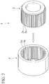
- FIG. 2 is an exploded perspective view showing the spline connection structure 1 of the present embodiment.
- the spline connection structure 1 of the present embodiment is used as a connection structure between the rotor 16a of the low-pressure turbine 16 and the low-pressure shaft 17 and a connection structure between the rotor 11a of the fan 11 and the low-pressure shaft 17 in the above-described jet engine 10, and is a structure that connects the shaft portion 2 and the cylindrical portion 3.
- the shaft portion 2 has teeth 2a formed at equal intervals on an outer circumferential surface.
- a single tooth 2a is formed to extend in the axial direction of the shaft portion 2 and has a substantially trapezoidal cross-section.
- the cylindrical portion 3 is a hollow member having the shaft portion 2 inserted thereinto, and has grooves 3a into which the teeth 2a of the shaft portion 2 are fitted formed at an inner circumferential surface.
- a single groove 3a has a substantially trapezoidal cross-section.
- FIG. 3A is a partially enlarged perspective view of a state in which the shaft portion 2 and the cylindrical portion 3 are fitted together. Also, FIG.
- 3B is a partially enlarged view of the state in which the shaft portion 2 and the cylindrical portion 3 are fitted together, viewed from the axial direction of the shaft portion 2.
- the teeth 2a of the shaft portion 2 are fitted into the grooves 3a of the cylindrical portion 3. In this way, the shaft portion 2 and the cylindrical portion 3 are fixed in the circumferential direction.
- FIG. 4 's (a) and FIG. 4 's (b) are schematic views showing the shape of the shaft portion 2.
- FIG. 4 's (a) is a view of a tooth groove sandwiched between two teeth 2a that is viewed from a diameter direction of the shaft portion 2, and FIG. 4 's (a) corresponds to a cross-sectional view taken along the line GA-GA in FIG. 4 's (b).
- FIG. 4 's (b) is a side view of the tooth 2a.
- the teeth 2a are arranged at equal intervals in the circumferential direction. For this reason, as show in FIG. 4 's (a), tooth surfaces 2b of adjacent teeth 2a are arranged to face each other.
- the adjacent tooth surfaces 2b facing each other are bent while maintaining a constant distance therebetween in a tooth width direction (a vertical direction in FIG. 4 's (a)) when viewed from a diameter direction of the shaft portion 2. That is, in the spline connection structure 1 of the present embodiment, as show in FIG. 4 's (a), the two tooth surfaces 2b are bent in the circumferential direction of the shaft portion 2 throughout the tooth width direction while a separation distance between the tooth surfaces 2b at the position A, a separation distance between the tooth surfaces 2b at the position B, and a separation distance between the tooth surfaces 2b at a position C are the same.
- FIG. 4 's (a) the shaft portion 2 is rotated so that the teeth 2a move to the right.
- one tooth surface 2b is downstream (to the right in FIG. 4 's (a)) and is upstream (to the left in FIG. 4 's (a)) in a moving direction of the tooth 2a when the shaft portion 2 is rotated.
- the downstream tooth surface 2b is bent so that a central portion thereof in the tooth width direction bulges toward the downstream side in the moving direction of the tooth 2a.
- the upstream tooth surface 2b is bent so that the central portion thereof in the tooth width direction is recessed toward the downstream side in the moving direction of the tooth 2a.
- FIG. 5 is a schematic view showing a bent state of the tooth surface 2b.
- the tooth surface 2b is bent along an arc having a radius of curvature R1 with a center of curvature O1 as the center. That is, in the spline connection structure 1 of the present embodiment, the tooth surface 2b is bent with a constant radius of curvature R1 when viewed from the diameter direction of the shaft portion 2.
- the adjacent tooth surfaces 2b facing each other are bent while maintaining a constant distance therebetween in the tooth width direction when viewed from the diameter direction of the shaft portion 2.
- the radii of curvature of all the tooth surfaces 2b are the same. Therefore, the positions of the centers of curvature 01 of the adjacent tooth surfaces 2b facing each other are spaced apart in the circumferential direction of the shaft portion 2 by the same distance as the separation distance between the tooth surfaces 2b.
- the center of curvature 01 is arranged to be closer to a side on which the torque acting on the tooth 2a is small than to a central position in the tooth width direction (a vertical direction in FIG. 5 ) by a distance D3.
- the position of the center of curvature O1 of the tooth surface 2b is set to be located on the side on which the torque acting on the tooth 2a is small in the tooth width direction.
- the center of curvature O1 is set to be located on a side on which the torque is smaller than at the central position in the tooth width direction, e.g., on the rear side of the jet engine 10.
- the center of curvature O1 is set to be located on a side on which the torque is smaller than at the central position in the tooth width direction, e.g., on the front side of the jet engine 10.
- a difference distance D1 between the position of the tooth surface 2b at the position C, which is spaced apart from the central position B toward the side on which the torque is larger, and the position T is larger than a difference distance D2 between the position of the tooth surface 2b at the position A, which is spaced apart from the central position B by the same distance as the distance between the central position B and the position C toward the side on which the torque is smaller, and the position T. Because a twist angle of the shaft portion 2 increases at a location at which the torque acting on the tooth 2a is large, the tooth surface 2b may become closer to a flat surface during rotation when the difference distance D1 is made larger than the difference distance D2.
- a cross-sectional shape thereof at the central position B has a shape that is rotated by an angle ⁇ in the circumferential direction of the shaft portion 2 about the axial center of the shaft portion 2 with respect to a cross-sectional shape thereof at the position A, as show in FIG. 6 .
- a cross-sectional shape thereof at the position C has a shape that is rotated in the circumferential direction of the shaft portion 2 about the axial center of the shaft portion 2 with respect to the cross-sectional shape thereof at the central position B.
- the shaft portion 2 can be formed in a short time by processing using a hob cutter.
- FIG. 7A and FIG. 7B are schematic views showing a process of forming the shaft portion 2.
- FIG. 7A is a perspective view
- FIG. 7B is a plan view.
- the hob cutter 100 that rotates at a constant speed is brought into contact with the circumferential surface of the shaft portion 2, and the tooth 2a is formed by moving the hob cutter 100 at a constant speed in the axial direction of the shaft portion 2.
- the shaft portion 2 used in the spline connection structure 1 of the present embodiment can be formed.
- the shaft portion 2 can be formed by cutting with the hob cutter 100 as described above.
- teeth can be formed in a shorter time compared to polishing with a grindstone. Therefore, the shaft portion 2 can be formed in a shorter time compared to the case in which the shaft portion is formed by polishing with a grindstone.
- the tooth surface 2b on the downstream side of the tooth 2a of the shaft portion 2 becomes a bent surface and a central portion thereof bulges, crowning is applied to the shaft portion 2. Consequently, according to the spline connection structure 1 of the present embodiment, the processing time of the shaft portion 2 to which crowning is applied can be reduced.
- the shaft portion 2 used in the spline connection structure 1 of the present embodiment can also be formed using a tool such as a pinion cutter, a shaving cutter, and so on.
- a working time for forming the shaft portion 2 and a working time for forming a shaft portion having the same size as that of the shaft portion 2 by polishing with a grindstone were compared.
- the working time for forming the shaft portion 2 was one hour whereas the working time for forming the shaft portion by polishing with a grindstone was six hours. In other words, by using the shaft portion 2, the working time for forming a shaft portion could be shortened to 1/6.
- the tooth surface 2b is bent with a constant radius of curvature R1 when viewed from the diameter direction of the shaft portion 2.
- the center of curvature 01 of the tooth surface 2b is set to be located on the side on which the torque acting on the tooth 2a is small in the tooth width direction.
- the position T at which the tooth surface 2b bulges most may be displaced toward the side on which the torque is small, and the difference distance (a distance between a position of the tooth surface 2b at the position T and a position of the tooth surface 2b at a target position in the circumferential direction of the shaft portion 2) D1 on the side on which the torque is large can be made to be larger than the difference distance D2 on the side on which the torque is small.
- the tooth surface 2b can be made to be closer to a flat surface when the shaft portion 2 is rotating, and a large contact area can be secured between the shaft portion 2 and the cylindrical portion 3.
- a constitution in which the tooth surface 2b is bent with a constant radius of curvature R1 is adopted.
- the present disclosure is not limited thereto.
- a radius of curvature of an area Ra in which the torque is large may be different from a radius of curvature of an area Rb in which the torque is small.
- a constitution in which the tooth surface 2b is bent in a shape in which curves having different radii of curvature are continuously connected when viewed from the diameter direction of the shaft portion 2 may also be adopted.
- the shape of the tooth surface 2b can be more flexibly changed so that the tooth surface 2b becomes closer to a flat surface when the shaft portion 2 rotates. Even in this case, the shaft portion 2 can be formed in a short time just by changing the rotational speed of the shaft portion 2 at the time of cutting the shaft portion 2 by the hob cutter 100.
- a radius of curvature R2 of the area Rb in which the torque is small may be set to be larger than a radius of curvature R1 of the area Ra in which the torque is large. That is, the tooth surface 2b may be bent so that a shape in which a curve having a large radius of curvature is arranged on the side on which the torque acting on a tooth is small in the tooth width direction and a curve having a small radius of curvature is arranged on the side on which the torque acting on the tooth is large in the tooth width direction is formed.
- the difference distance on the side on which the torque acting on the tooth is large in the tooth width direction may be made to be larger than the difference distance on the side on which the torque acting on the tooth is small in the tooth width direction.
- the tooth surface 2b may be made to be closer to a flat surface during rotation.
- the spline connection structure 1 of the present embodiment is applied to the connection location between the low-pressure turbine 16 and the low-pressure shaft 17 and the connection location between the fan 11 and the low-pressure shaft 17 have been described.
- the present disclosure is not limited thereto.
- the spline connection structure 1 may also be applied to a connection location between the high-pressure turbine 14 and the high-pressure shaft 15 and a connection location between the compressor 12 and the high-pressure shaft 15.
- the spline connection structure 1 may also be applied to a jet engine having a constitution other than that of the jet engine 10 show in FIG. 1 .
- the spline connection structure 1 may also be applied to apparatuses other than jet engines.
- the processing time of the shaft portion to which crowning is applied used for the spline connection structure can be allowed to be reduced.
Landscapes
- Engineering & Computer Science (AREA)
- General Engineering & Computer Science (AREA)
- Mechanical Engineering (AREA)
- Ocean & Marine Engineering (AREA)
- Shafts, Cranks, Connecting Bars, And Related Bearings (AREA)
Applications Claiming Priority (2)
| Application Number | Priority Date | Filing Date | Title |
|---|---|---|---|
| JP2015075988A JP6540167B2 (ja) | 2015-04-02 | 2015-04-02 | スプライン接続構造及びスプラインシャフト |
| PCT/JP2016/054270 WO2016158036A1 (fr) | 2015-04-02 | 2016-02-15 | Structure de liaison à cannelures et arbre cannelé |
Publications (3)
| Publication Number | Publication Date |
|---|---|
| EP3232075A1 true EP3232075A1 (fr) | 2017-10-18 |
| EP3232075A4 EP3232075A4 (fr) | 2018-05-23 |
| EP3232075B1 EP3232075B1 (fr) | 2019-10-02 |
Family
ID=57004902
Family Applications (1)
| Application Number | Title | Priority Date | Filing Date |
|---|---|---|---|
| EP16771920.2A Active EP3232075B1 (fr) | 2015-04-02 | 2016-02-15 | Structure de liaison à cannelures et arbre cannelé |
Country Status (4)
| Country | Link |
|---|---|
| US (1) | US10247247B2 (fr) |
| EP (1) | EP3232075B1 (fr) |
| JP (1) | JP6540167B2 (fr) |
| WO (1) | WO2016158036A1 (fr) |
Cited By (2)
| Publication number | Priority date | Publication date | Assignee | Title |
|---|---|---|---|---|
| EP3508687A1 (fr) * | 2018-01-08 | 2019-07-10 | United Technologies Corporation | Ensemble d'alignement gérant les cannelures tolérant les dommages |
| WO2025062089A1 (fr) * | 2023-09-22 | 2025-03-27 | Safran Aircraft Engines | Pièce tournante pour turbomachine d'aéronef |
Families Citing this family (3)
| Publication number | Priority date | Publication date | Assignee | Title |
|---|---|---|---|---|
| WO2018070180A1 (fr) * | 2016-10-11 | 2018-04-19 | 日立オートモティブシステムズ株式会社 | Arbre de roue à aubes et procédé de production associé |
| DE102019210419A1 (de) * | 2019-07-15 | 2021-01-21 | Rolls-Royce Deutschland Ltd & Co Kg | Wellenverbindung |
| JP7610427B2 (ja) * | 2021-02-25 | 2025-01-08 | Ntn株式会社 | 車輪用軸受装置および動力伝達構造 |
Family Cites Families (22)
| Publication number | Priority date | Publication date | Assignee | Title |
|---|---|---|---|---|
| US1381805A (en) * | 1919-12-09 | 1921-06-14 | Courtaulds Ltd | Spinning-box mounting |
| US1443837A (en) * | 1920-01-10 | 1923-01-30 | Newark Gearcutting Machine Co | Sinusoidal gearing |
| JPS6345223U (fr) | 1986-09-04 | 1988-03-26 | ||
| JPH0633220Y2 (ja) | 1986-09-04 | 1994-08-31 | エヌティエヌ株式会社 | 車両用駆動力伝達構造 |
| GB8711700D0 (en) * | 1987-05-18 | 1987-06-24 | Green P C | Mechanical coupling |
| US4875796A (en) * | 1987-11-23 | 1989-10-24 | Eaton Corporation | Press-fit splined connection |
| JP3052037B2 (ja) | 1993-07-22 | 2000-06-12 | 本田技研工業株式会社 | スプライン結合構造 |
| US5580183A (en) | 1994-04-29 | 1996-12-03 | United Technologies Corporation | Gas turbine engine spline arrangement |
| US5533825A (en) * | 1994-11-14 | 1996-07-09 | General Electric Company | Parabolically helical spline shaft coupling |
| JPH0925941A (ja) * | 1995-07-11 | 1997-01-28 | Aichi Mach Ind Co Ltd | スプライン嵌合構造 |
| JPH09141354A (ja) | 1995-11-20 | 1997-06-03 | Aisin Seiki Co Ltd | 中空シャフトの高歯たけスプライン製造方法および高歯たけスプラインを備えた中空シャフト |
| DE19613462C2 (de) * | 1996-04-04 | 1999-10-14 | Hubert Taubert | Gelenkverbindung zur Drehübertragung |
| JP2002327771A (ja) * | 2001-05-02 | 2002-11-15 | Ishikawajima Harima Heavy Ind Co Ltd | スプライン継手 |
| JP2005009615A (ja) | 2003-06-20 | 2005-01-13 | Ntn Corp | 動力伝達部材のスプライン嵌合構造 |
| US7040870B2 (en) * | 2003-12-30 | 2006-05-09 | The Goodyear Tire & Rubber Company | Gear pump with gears having curved teeth and method of feeding elastomeric material |
| US7288029B1 (en) * | 2005-01-19 | 2007-10-30 | Gkn Driveline North America, Inc. | Propshaft with crash-worthiness |
| US7493754B2 (en) | 2005-10-19 | 2009-02-24 | General Electric Company | Gas turbine engine assembly and methods of assembling same |
| JP2007198401A (ja) | 2006-01-23 | 2007-08-09 | Ntn Corp | スプライン連結構造、動力伝達シャフト、等速自在継手の外輪ステム |
| JP2007247771A (ja) * | 2006-03-15 | 2007-09-27 | Ntn Corp | トルク伝達機構 |
| JP5093003B2 (ja) | 2008-08-29 | 2012-12-05 | トヨタ自動車株式会社 | スプラインシャフト、及び、スプラインシャフトの製造方法 |
| US8348542B2 (en) * | 2009-04-13 | 2013-01-08 | Gandy Technologies Corporation | Connection system for tubular members |
| US9382001B2 (en) * | 2014-07-23 | 2016-07-05 | Bell Helicopter Textron Inc. | Torque transfer system for a rotorcraft |
-
2015
- 2015-04-02 JP JP2015075988A patent/JP6540167B2/ja active Active
-
2016
- 2016-02-15 WO PCT/JP2016/054270 patent/WO2016158036A1/fr not_active Ceased
- 2016-02-15 EP EP16771920.2A patent/EP3232075B1/fr active Active
-
2017
- 2017-07-11 US US15/646,319 patent/US10247247B2/en active Active
Cited By (3)
| Publication number | Priority date | Publication date | Assignee | Title |
|---|---|---|---|---|
| EP3508687A1 (fr) * | 2018-01-08 | 2019-07-10 | United Technologies Corporation | Ensemble d'alignement gérant les cannelures tolérant les dommages |
| WO2025062089A1 (fr) * | 2023-09-22 | 2025-03-27 | Safran Aircraft Engines | Pièce tournante pour turbomachine d'aéronef |
| FR3153370A1 (fr) * | 2023-09-22 | 2025-03-28 | Safran Aircraft Engines | Pièce tournante pour turbomachine d’aéronef |
Also Published As
| Publication number | Publication date |
|---|---|
| EP3232075A4 (fr) | 2018-05-23 |
| JP6540167B2 (ja) | 2019-07-10 |
| US20170307023A1 (en) | 2017-10-26 |
| EP3232075B1 (fr) | 2019-10-02 |
| JP2016196902A (ja) | 2016-11-24 |
| WO2016158036A1 (fr) | 2016-10-06 |
| US10247247B2 (en) | 2019-04-02 |
Similar Documents
| Publication | Publication Date | Title |
|---|---|---|
| US10247247B2 (en) | Spline connection structure and spline shaft | |
| RU2341660C2 (ru) | Лопатка двойной кривизны для направляющего аппарата турбомашины | |
| EP2500525B1 (fr) | Tige d'amortissement | |
| US20090123286A1 (en) | Assembly of a fan blade and of its damper, fan blade damper and method for calibrating the damper | |
| US8951014B2 (en) | Turbine blade with mate face cooling air flow | |
| GB2455622A (en) | A plunge milling method | |
| CN103201460B (zh) | 旋转机械的静叶片单元及其制造方法以及结合方法 | |
| US7524165B2 (en) | Control lever for the angular setting of a stator blade in a turboshaft engine | |
| EP3171002B1 (fr) | Carter de soufflante pour turboréacteur à double flux | |
| US10094281B2 (en) | Gas turbine engine with twin offset gas generators | |
| EP2987959A2 (fr) | Joint d'étanchéité avec fonction de refroidissement | |
| US8936439B2 (en) | Radial turbine backface curvature stress reduction | |
| US20120128497A1 (en) | Turbine engine compressor stator | |
| EP2971523B1 (fr) | Élément de fixation d'une aube de turbine à gaz ayant un profil incurvé | |
| US20180128118A1 (en) | Turbine airfoil attachment with multi-radial serration profile | |
| EP2915978A1 (fr) | Zones de compresseur pour moteur à turbine à gaz à rapport de pression globale élevé | |
| EP3095959A1 (fr) | Procédé de conception et de fabrication de pale de rotor | |
| EP3333373B1 (fr) | Arbres concentriques entrainant des soufflantes adjacentes pour la propulsion d'un aéronef | |
| US9976428B2 (en) | Turbine airfoil attachment with serration profile | |
| US10087762B2 (en) | Scallop curvature for radial turbine wheel | |
| CA2886820A1 (fr) | Logement a facettes pour compresseur de turbo axial | |
| US20180073399A1 (en) | Turbine blade assembly arrangement and corresponding assembly tool | |
| US10821575B2 (en) | Clamp assembly and method | |
| EP3303773B1 (fr) | Système de fixation pour surface portante de turbine utilisable dans une turbine à gaz | |
| JP2012172575A (ja) | 静翼列部 |
Legal Events
| Date | Code | Title | Description |
|---|---|---|---|
| STAA | Information on the status of an ep patent application or granted ep patent |
Free format text: STATUS: THE INTERNATIONAL PUBLICATION HAS BEEN MADE |
|
| PUAI | Public reference made under article 153(3) epc to a published international application that has entered the european phase |
Free format text: ORIGINAL CODE: 0009012 |
|
| STAA | Information on the status of an ep patent application or granted ep patent |
Free format text: STATUS: REQUEST FOR EXAMINATION WAS MADE |
|
| 17P | Request for examination filed |
Effective date: 20170714 |
|
| AK | Designated contracting states |
Kind code of ref document: A1 Designated state(s): AL AT BE BG CH CY CZ DE DK EE ES FI FR GB GR HR HU IE IS IT LI LT LU LV MC MK MT NL NO PL PT RO RS SE SI SK SM TR |
|
| AX | Request for extension of the european patent |
Extension state: BA ME |
|
| A4 | Supplementary search report drawn up and despatched |
Effective date: 20180419 |
|
| RIC1 | Information provided on ipc code assigned before grant |
Ipc: F01D 5/02 20060101ALI20180413BHEP Ipc: F16D 1/10 20060101ALI20180413BHEP Ipc: F16D 1/02 20060101AFI20180413BHEP Ipc: F16C 3/03 20060101ALI20180413BHEP |
|
| DAV | Request for validation of the european patent (deleted) | ||
| DAX | Request for extension of the european patent (deleted) | ||
| GRAP | Despatch of communication of intention to grant a patent |
Free format text: ORIGINAL CODE: EPIDOSNIGR1 |
|
| STAA | Information on the status of an ep patent application or granted ep patent |
Free format text: STATUS: GRANT OF PATENT IS INTENDED |
|
| INTG | Intention to grant announced |
Effective date: 20190426 |
|
| GRAS | Grant fee paid |
Free format text: ORIGINAL CODE: EPIDOSNIGR3 |
|
| GRAA | (expected) grant |
Free format text: ORIGINAL CODE: 0009210 |
|
| STAA | Information on the status of an ep patent application or granted ep patent |
Free format text: STATUS: THE PATENT HAS BEEN GRANTED |
|
| AK | Designated contracting states |
Kind code of ref document: B1 Designated state(s): AL AT BE BG CH CY CZ DE DK EE ES FI FR GB GR HR HU IE IS IT LI LT LU LV MC MK MT NL NO PL PT RO RS SE SI SK SM TR |
|
| REG | Reference to a national code |
Ref country code: GB Ref legal event code: FG4D |
|
| REG | Reference to a national code |
Ref country code: CH Ref legal event code: EP Ref country code: AT Ref legal event code: REF Ref document number: 1186511 Country of ref document: AT Kind code of ref document: T Effective date: 20191015 |
|
| REG | Reference to a national code |
Ref country code: DE Ref legal event code: R096 Ref document number: 602016021777 Country of ref document: DE |
|
| REG | Reference to a national code |
Ref country code: IE Ref legal event code: FG4D |
|
| REG | Reference to a national code |
Ref country code: NL Ref legal event code: MP Effective date: 20191002 |
|
| REG | Reference to a national code |
Ref country code: LT Ref legal event code: MG4D |
|
| REG | Reference to a national code |
Ref country code: AT Ref legal event code: MK05 Ref document number: 1186511 Country of ref document: AT Kind code of ref document: T Effective date: 20191002 |
|
| PG25 | Lapsed in a contracting state [announced via postgrant information from national office to epo] |
Ref country code: AT Free format text: LAPSE BECAUSE OF FAILURE TO SUBMIT A TRANSLATION OF THE DESCRIPTION OR TO PAY THE FEE WITHIN THE PRESCRIBED TIME-LIMIT Effective date: 20191002 Ref country code: NL Free format text: LAPSE BECAUSE OF FAILURE TO SUBMIT A TRANSLATION OF THE DESCRIPTION OR TO PAY THE FEE WITHIN THE PRESCRIBED TIME-LIMIT Effective date: 20191002 Ref country code: SE Free format text: LAPSE BECAUSE OF FAILURE TO SUBMIT A TRANSLATION OF THE DESCRIPTION OR TO PAY THE FEE WITHIN THE PRESCRIBED TIME-LIMIT Effective date: 20191002 Ref country code: LV Free format text: LAPSE BECAUSE OF FAILURE TO SUBMIT A TRANSLATION OF THE DESCRIPTION OR TO PAY THE FEE WITHIN THE PRESCRIBED TIME-LIMIT Effective date: 20191002 Ref country code: LT Free format text: LAPSE BECAUSE OF FAILURE TO SUBMIT A TRANSLATION OF THE DESCRIPTION OR TO PAY THE FEE WITHIN THE PRESCRIBED TIME-LIMIT Effective date: 20191002 Ref country code: GR Free format text: LAPSE BECAUSE OF FAILURE TO SUBMIT A TRANSLATION OF THE DESCRIPTION OR TO PAY THE FEE WITHIN THE PRESCRIBED TIME-LIMIT Effective date: 20200103 Ref country code: NO Free format text: LAPSE BECAUSE OF FAILURE TO SUBMIT A TRANSLATION OF THE DESCRIPTION OR TO PAY THE FEE WITHIN THE PRESCRIBED TIME-LIMIT Effective date: 20200102 Ref country code: PL Free format text: LAPSE BECAUSE OF FAILURE TO SUBMIT A TRANSLATION OF THE DESCRIPTION OR TO PAY THE FEE WITHIN THE PRESCRIBED TIME-LIMIT Effective date: 20191002 Ref country code: ES Free format text: LAPSE BECAUSE OF FAILURE TO SUBMIT A TRANSLATION OF THE DESCRIPTION OR TO PAY THE FEE WITHIN THE PRESCRIBED TIME-LIMIT Effective date: 20191002 Ref country code: PT Free format text: LAPSE BECAUSE OF FAILURE TO SUBMIT A TRANSLATION OF THE DESCRIPTION OR TO PAY THE FEE WITHIN THE PRESCRIBED TIME-LIMIT Effective date: 20200203 Ref country code: BG Free format text: LAPSE BECAUSE OF FAILURE TO SUBMIT A TRANSLATION OF THE DESCRIPTION OR TO PAY THE FEE WITHIN THE PRESCRIBED TIME-LIMIT Effective date: 20200102 Ref country code: FI Free format text: LAPSE BECAUSE OF FAILURE TO SUBMIT A TRANSLATION OF THE DESCRIPTION OR TO PAY THE FEE WITHIN THE PRESCRIBED TIME-LIMIT Effective date: 20191002 |
|
| PG25 | Lapsed in a contracting state [announced via postgrant information from national office to epo] |
Ref country code: RS Free format text: LAPSE BECAUSE OF FAILURE TO SUBMIT A TRANSLATION OF THE DESCRIPTION OR TO PAY THE FEE WITHIN THE PRESCRIBED TIME-LIMIT Effective date: 20191002 Ref country code: IS Free format text: LAPSE BECAUSE OF FAILURE TO SUBMIT A TRANSLATION OF THE DESCRIPTION OR TO PAY THE FEE WITHIN THE PRESCRIBED TIME-LIMIT Effective date: 20200224 Ref country code: CZ Free format text: LAPSE BECAUSE OF FAILURE TO SUBMIT A TRANSLATION OF THE DESCRIPTION OR TO PAY THE FEE WITHIN THE PRESCRIBED TIME-LIMIT Effective date: 20191002 Ref country code: HR Free format text: LAPSE BECAUSE OF FAILURE TO SUBMIT A TRANSLATION OF THE DESCRIPTION OR TO PAY THE FEE WITHIN THE PRESCRIBED TIME-LIMIT Effective date: 20191002 |
|
| PG25 | Lapsed in a contracting state [announced via postgrant information from national office to epo] |
Ref country code: AL Free format text: LAPSE BECAUSE OF FAILURE TO SUBMIT A TRANSLATION OF THE DESCRIPTION OR TO PAY THE FEE WITHIN THE PRESCRIBED TIME-LIMIT Effective date: 20191002 |
|
| REG | Reference to a national code |
Ref country code: DE Ref legal event code: R097 Ref document number: 602016021777 Country of ref document: DE |
|
| PG2D | Information on lapse in contracting state deleted |
Ref country code: IS |
|
| PG25 | Lapsed in a contracting state [announced via postgrant information from national office to epo] |
Ref country code: RO Free format text: LAPSE BECAUSE OF FAILURE TO SUBMIT A TRANSLATION OF THE DESCRIPTION OR TO PAY THE FEE WITHIN THE PRESCRIBED TIME-LIMIT Effective date: 20191002 Ref country code: DK Free format text: LAPSE BECAUSE OF FAILURE TO SUBMIT A TRANSLATION OF THE DESCRIPTION OR TO PAY THE FEE WITHIN THE PRESCRIBED TIME-LIMIT Effective date: 20191002 Ref country code: EE Free format text: LAPSE BECAUSE OF FAILURE TO SUBMIT A TRANSLATION OF THE DESCRIPTION OR TO PAY THE FEE WITHIN THE PRESCRIBED TIME-LIMIT Effective date: 20191002 Ref country code: IS Free format text: LAPSE BECAUSE OF FAILURE TO SUBMIT A TRANSLATION OF THE DESCRIPTION OR TO PAY THE FEE WITHIN THE PRESCRIBED TIME-LIMIT Effective date: 20200202 |
|
| PLBE | No opposition filed within time limit |
Free format text: ORIGINAL CODE: 0009261 |
|
| STAA | Information on the status of an ep patent application or granted ep patent |
Free format text: STATUS: NO OPPOSITION FILED WITHIN TIME LIMIT |
|
| PG25 | Lapsed in a contracting state [announced via postgrant information from national office to epo] |
Ref country code: SK Free format text: LAPSE BECAUSE OF FAILURE TO SUBMIT A TRANSLATION OF THE DESCRIPTION OR TO PAY THE FEE WITHIN THE PRESCRIBED TIME-LIMIT Effective date: 20191002 Ref country code: SM Free format text: LAPSE BECAUSE OF FAILURE TO SUBMIT A TRANSLATION OF THE DESCRIPTION OR TO PAY THE FEE WITHIN THE PRESCRIBED TIME-LIMIT Effective date: 20191002 |
|
| 26N | No opposition filed |
Effective date: 20200703 |
|
| REG | Reference to a national code |
Ref country code: CH Ref legal event code: PL |
|
| REG | Reference to a national code |
Ref country code: BE Ref legal event code: MM Effective date: 20200229 |
|
| PG25 | Lapsed in a contracting state [announced via postgrant information from national office to epo] |
Ref country code: MC Free format text: LAPSE BECAUSE OF FAILURE TO SUBMIT A TRANSLATION OF THE DESCRIPTION OR TO PAY THE FEE WITHIN THE PRESCRIBED TIME-LIMIT Effective date: 20191002 Ref country code: LU Free format text: LAPSE BECAUSE OF NON-PAYMENT OF DUE FEES Effective date: 20200215 |
|
| PG25 | Lapsed in a contracting state [announced via postgrant information from national office to epo] |
Ref country code: SI Free format text: LAPSE BECAUSE OF FAILURE TO SUBMIT A TRANSLATION OF THE DESCRIPTION OR TO PAY THE FEE WITHIN THE PRESCRIBED TIME-LIMIT Effective date: 20191002 Ref country code: CH Free format text: LAPSE BECAUSE OF NON-PAYMENT OF DUE FEES Effective date: 20200229 Ref country code: LI Free format text: LAPSE BECAUSE OF NON-PAYMENT OF DUE FEES Effective date: 20200229 |
|
| PG25 | Lapsed in a contracting state [announced via postgrant information from national office to epo] |
Ref country code: IE Free format text: LAPSE BECAUSE OF NON-PAYMENT OF DUE FEES Effective date: 20200215 |
|
| PG25 | Lapsed in a contracting state [announced via postgrant information from national office to epo] |
Ref country code: BE Free format text: LAPSE BECAUSE OF NON-PAYMENT OF DUE FEES Effective date: 20200229 |
|
| PG25 | Lapsed in a contracting state [announced via postgrant information from national office to epo] |
Ref country code: TR Free format text: LAPSE BECAUSE OF FAILURE TO SUBMIT A TRANSLATION OF THE DESCRIPTION OR TO PAY THE FEE WITHIN THE PRESCRIBED TIME-LIMIT Effective date: 20191002 Ref country code: MT Free format text: LAPSE BECAUSE OF FAILURE TO SUBMIT A TRANSLATION OF THE DESCRIPTION OR TO PAY THE FEE WITHIN THE PRESCRIBED TIME-LIMIT Effective date: 20191002 Ref country code: CY Free format text: LAPSE BECAUSE OF FAILURE TO SUBMIT A TRANSLATION OF THE DESCRIPTION OR TO PAY THE FEE WITHIN THE PRESCRIBED TIME-LIMIT Effective date: 20191002 |
|
| PG25 | Lapsed in a contracting state [announced via postgrant information from national office to epo] |
Ref country code: MK Free format text: LAPSE BECAUSE OF FAILURE TO SUBMIT A TRANSLATION OF THE DESCRIPTION OR TO PAY THE FEE WITHIN THE PRESCRIBED TIME-LIMIT Effective date: 20191002 |
|
| PGFP | Annual fee paid to national office [announced via postgrant information from national office to epo] |
Ref country code: GB Payment date: 20260122 Year of fee payment: 11 |
|
| PGFP | Annual fee paid to national office [announced via postgrant information from national office to epo] |
Ref country code: DE Payment date: 20260121 Year of fee payment: 11 |
|
| PGFP | Annual fee paid to national office [announced via postgrant information from national office to epo] |
Ref country code: IT Payment date: 20260121 Year of fee payment: 11 |
|
| PGFP | Annual fee paid to national office [announced via postgrant information from national office to epo] |
Ref country code: FR Payment date: 20260121 Year of fee payment: 11 |