EP3232762B1 - Mappage pour tondeuse à gazon robotisée - Google Patents
Mappage pour tondeuse à gazon robotisée Download PDFInfo
- Publication number
- EP3232762B1 EP3232762B1 EP15771412.2A EP15771412A EP3232762B1 EP 3232762 B1 EP3232762 B1 EP 3232762B1 EP 15771412 A EP15771412 A EP 15771412A EP 3232762 B1 EP3232762 B1 EP 3232762B1
- Authority
- EP
- European Patent Office
- Prior art keywords
- robot lawnmower
- area
- mapping data
- map image
- mobile device
- Prior art date
- Legal status (The legal status is an assumption and is not a legal conclusion. Google has not performed a legal analysis and makes no representation as to the accuracy of the status listed.)
- Active
Links
Images






Classifications
-
- G—PHYSICS
- G01—MEASURING; TESTING
- G01C—MEASURING DISTANCES, LEVELS OR BEARINGS; SURVEYING; NAVIGATION; GYROSCOPIC INSTRUMENTS; PHOTOGRAMMETRY OR VIDEOGRAMMETRY
- G01C21/00—Navigation; Navigational instruments not provided for in groups G01C1/00 - G01C19/00
- G01C21/20—Instruments for performing navigational calculations
-
- G—PHYSICS
- G05—CONTROLLING; REGULATING
- G05D—SYSTEMS FOR CONTROLLING OR REGULATING NON-ELECTRIC VARIABLES
- G05D1/00—Control of position, course, altitude or attitude of land, water, air or space vehicles, e.g. using automatic pilots
- G05D1/0011—Control of position, course, altitude or attitude of land, water, air or space vehicles, e.g. using automatic pilots associated with a remote control arrangement
- G05D1/0044—Control of position, course, altitude or attitude of land, water, air or space vehicles, e.g. using automatic pilots associated with a remote control arrangement by providing the operator with a computer generated representation of the environment of the vehicle, e.g. virtual reality, maps
-
- A—HUMAN NECESSITIES
- A01—AGRICULTURE; FORESTRY; ANIMAL HUSBANDRY; HUNTING; TRAPPING; FISHING
- A01D—HARVESTING; MOWING
- A01D34/00—Mowers; Mowing apparatus of harvesters
- A01D34/006—Control or measuring arrangements
- A01D34/008—Control or measuring arrangements for automated or remotely controlled operation
-
- G—PHYSICS
- G01—MEASURING; TESTING
- G01C—MEASURING DISTANCES, LEVELS OR BEARINGS; SURVEYING; NAVIGATION; GYROSCOPIC INSTRUMENTS; PHOTOGRAMMETRY OR VIDEOGRAMMETRY
- G01C21/00—Navigation; Navigational instruments not provided for in groups G01C1/00 - G01C19/00
- G01C21/38—Electronic maps specially adapted for navigation; Updating thereof
- G01C21/3804—Creation or updating of map data
- G01C21/3807—Creation or updating of map data characterised by the type of data
-
- G—PHYSICS
- G01—MEASURING; TESTING
- G01S—RADIO DIRECTION-FINDING; RADIO NAVIGATION; DETERMINING DISTANCE OR VELOCITY BY USE OF RADIO WAVES; LOCATING OR PRESENCE-DETECTING BY USE OF THE REFLECTION OR RERADIATION OF RADIO WAVES; ANALOGOUS ARRANGEMENTS USING OTHER WAVES
- G01S19/00—Satellite radio beacon positioning systems; Determining position, velocity or attitude using signals transmitted by such systems
- G01S19/01—Satellite radio beacon positioning systems transmitting time-stamped messages, e.g. GPS [Global Positioning System], GLONASS [Global Orbiting Navigation Satellite System] or GALILEO
- G01S19/13—Receivers
-
- G—PHYSICS
- G05—CONTROLLING; REGULATING
- G05D—SYSTEMS FOR CONTROLLING OR REGULATING NON-ELECTRIC VARIABLES
- G05D1/00—Control of position, course, altitude or attitude of land, water, air or space vehicles, e.g. using automatic pilots
- G05D1/0088—Control of position, course, altitude or attitude of land, water, air or space vehicles, e.g. using automatic pilots characterized by the autonomous decision making process, e.g. artificial intelligence, predefined behaviours
-
- G—PHYSICS
- G05—CONTROLLING; REGULATING
- G05D—SYSTEMS FOR CONTROLLING OR REGULATING NON-ELECTRIC VARIABLES
- G05D1/00—Control of position, course, altitude or attitude of land, water, air or space vehicles, e.g. using automatic pilots
- G05D1/02—Control of position or course in two dimensions
- G05D1/021—Control of position or course in two dimensions specially adapted to land vehicles
- G05D1/0212—Control of position or course in two dimensions specially adapted to land vehicles with means for defining a desired trajectory
- G05D1/0219—Control of position or course in two dimensions specially adapted to land vehicles with means for defining a desired trajectory ensuring the processing of the whole working surface
-
- G—PHYSICS
- G05—CONTROLLING; REGULATING
- G05D—SYSTEMS FOR CONTROLLING OR REGULATING NON-ELECTRIC VARIABLES
- G05D1/00—Control of position, course, altitude or attitude of land, water, air or space vehicles, e.g. using automatic pilots
- G05D1/02—Control of position or course in two dimensions
- G05D1/021—Control of position or course in two dimensions specially adapted to land vehicles
- G05D1/0212—Control of position or course in two dimensions specially adapted to land vehicles with means for defining a desired trajectory
- G05D1/0221—Control of position or course in two dimensions specially adapted to land vehicles with means for defining a desired trajectory involving a learning process
-
- G—PHYSICS
- G05—CONTROLLING; REGULATING
- G05D—SYSTEMS FOR CONTROLLING OR REGULATING NON-ELECTRIC VARIABLES
- G05D1/00—Control of position, course, altitude or attitude of land, water, air or space vehicles, e.g. using automatic pilots
- G05D1/02—Control of position or course in two dimensions
- G05D1/021—Control of position or course in two dimensions specially adapted to land vehicles
- G05D1/0231—Control of position or course in two dimensions specially adapted to land vehicles using optical position detecting means
-
- G—PHYSICS
- G05—CONTROLLING; REGULATING
- G05D—SYSTEMS FOR CONTROLLING OR REGULATING NON-ELECTRIC VARIABLES
- G05D1/00—Control of position, course, altitude or attitude of land, water, air or space vehicles, e.g. using automatic pilots
- G05D1/02—Control of position or course in two dimensions
- G05D1/021—Control of position or course in two dimensions specially adapted to land vehicles
- G05D1/0231—Control of position or course in two dimensions specially adapted to land vehicles using optical position detecting means
- G05D1/0234—Control of position or course in two dimensions specially adapted to land vehicles using optical position detecting means using optical markers or beacons
-
- G—PHYSICS
- G05—CONTROLLING; REGULATING
- G05D—SYSTEMS FOR CONTROLLING OR REGULATING NON-ELECTRIC VARIABLES
- G05D1/00—Control of position, course, altitude or attitude of land, water, air or space vehicles, e.g. using automatic pilots
- G05D1/02—Control of position or course in two dimensions
- G05D1/021—Control of position or course in two dimensions specially adapted to land vehicles
- G05D1/0231—Control of position or course in two dimensions specially adapted to land vehicles using optical position detecting means
- G05D1/0234—Control of position or course in two dimensions specially adapted to land vehicles using optical position detecting means using optical markers or beacons
- G05D1/0236—Control of position or course in two dimensions specially adapted to land vehicles using optical position detecting means using optical markers or beacons in combination with a laser
-
- G—PHYSICS
- G05—CONTROLLING; REGULATING
- G05D—SYSTEMS FOR CONTROLLING OR REGULATING NON-ELECTRIC VARIABLES
- G05D1/00—Control of position, course, altitude or attitude of land, water, air or space vehicles, e.g. using automatic pilots
- G05D1/02—Control of position or course in two dimensions
- G05D1/021—Control of position or course in two dimensions specially adapted to land vehicles
- G05D1/0259—Control of position or course in two dimensions specially adapted to land vehicles using magnetic or electromagnetic means
- G05D1/0265—Control of position or course in two dimensions specially adapted to land vehicles using magnetic or electromagnetic means using buried wires
-
- G—PHYSICS
- G05—CONTROLLING; REGULATING
- G05D—SYSTEMS FOR CONTROLLING OR REGULATING NON-ELECTRIC VARIABLES
- G05D1/00—Control of position, course, altitude or attitude of land, water, air or space vehicles, e.g. using automatic pilots
- G05D1/02—Control of position or course in two dimensions
- G05D1/021—Control of position or course in two dimensions specially adapted to land vehicles
- G05D1/0268—Control of position or course in two dimensions specially adapted to land vehicles using internal positioning means
- G05D1/0274—Control of position or course in two dimensions specially adapted to land vehicles using internal positioning means using mapping information stored in a memory device
-
- G—PHYSICS
- G05—CONTROLLING; REGULATING
- G05D—SYSTEMS FOR CONTROLLING OR REGULATING NON-ELECTRIC VARIABLES
- G05D1/00—Control of position, course, altitude or attitude of land, water, air or space vehicles, e.g. using automatic pilots
- G05D1/02—Control of position or course in two dimensions
- G05D1/021—Control of position or course in two dimensions specially adapted to land vehicles
- G05D1/0276—Control of position or course in two dimensions specially adapted to land vehicles using signals provided by a source external to the vehicle
- G05D1/0278—Control of position or course in two dimensions specially adapted to land vehicles using signals provided by a source external to the vehicle using satellite positioning signals, e.g. GPS
-
- G—PHYSICS
- G05—CONTROLLING; REGULATING
- G05D—SYSTEMS FOR CONTROLLING OR REGULATING NON-ELECTRIC VARIABLES
- G05D1/00—Control of position, course, altitude or attitude of land, water, air or space vehicles, e.g. using automatic pilots
- G05D1/02—Control of position or course in two dimensions
- G05D1/021—Control of position or course in two dimensions specially adapted to land vehicles
- G05D1/0276—Control of position or course in two dimensions specially adapted to land vehicles using signals provided by a source external to the vehicle
- G05D1/028—Control of position or course in two dimensions specially adapted to land vehicles using signals provided by a source external to the vehicle using a RF signal
-
- A—HUMAN NECESSITIES
- A01—AGRICULTURE; FORESTRY; ANIMAL HUSBANDRY; HUNTING; TRAPPING; FISHING
- A01D—HARVESTING; MOWING
- A01D2101/00—Lawn-mowers
-
- Y—GENERAL TAGGING OF NEW TECHNOLOGICAL DEVELOPMENTS; GENERAL TAGGING OF CROSS-SECTIONAL TECHNOLOGIES SPANNING OVER SEVERAL SECTIONS OF THE IPC; TECHNICAL SUBJECTS COVERED BY FORMER USPC CROSS-REFERENCE ART COLLECTIONS [XRACs] AND DIGESTS
- Y10—TECHNICAL SUBJECTS COVERED BY FORMER USPC
- Y10S—TECHNICAL SUBJECTS COVERED BY FORMER USPC CROSS-REFERENCE ART COLLECTIONS [XRACs] AND DIGESTS
- Y10S901/00—Robots
- Y10S901/01—Mobile robot
Definitions
- This invention relates to mapping an area to be mowed by a robot lawnmower.
- Robots that perform household functions such as floor cleaning and lawn cutting are now readily available consumer products.
- Some robots are generally confined within (i) touched walls and other obstacles within the rooms of a dwelling, (ii) IR-detected staircases (cliffs) leading downward; and/or (iii) user-placed detectable barriers such as directed IR beams, physical barriers or magnetic tape. Walls often provide much of the confinement perimeter.
- Other robots may try to map the dwelling using a complex system of sensors and/or active or passive beacons (e.g., sonar, RFID or bar code detection, or various kinds of machine vision).
- a continuous boundary marker e.g., a boundary wire
- the boundary wire is intended to confine the robot within the lawn or other appropriate area, so as to avoid damaging non-grassy areas of the yard or intruding onto a neighboring property.
- the boundary wire is typically a continuous electrically conductive loop around the property to be mowed. Although the boundary wire can be drawn into the property in peninsulas to surround gardens or other off-limit areas, it remains a continuous loop, and is energized with an AC current detectable as a magnetic field at a distance of a few feet.
- the boundary wire loop must be supplied with power, usually from a wall socket. Within the bounded area, a mowing robot may "bounce" randomly as the robot nears the guide conductor, or may follow along the guide conductor. Some mowers also touch and bounce from physical barriers.
- US 2002/156556 A1 describes a multifunctional mobile appliance capable of discerning its position anywhere on or above the surface of the earth to a precision of a centimeter or better using the Real Time Kinematic Global Positioning System (RTK-GPS), an impulse radio system, or other similar high-precision positioning systems. More specific, the appliance independently and accurately maps the work area and proceeds to perform one or more tasks over that area, as directed by the user. These tasks include, but are not limited to, mowing, vacuuming, scrubbing, waxing, and polishing. The user may control, through the World Wide Web, what tasks are performed where and when. Both the user and the appliance can make use of services that are provided on the Internet to enhance the performance of the appliance. The appliance is safe, silent, self-sufficient, nimble, and non-polluting. It is equipped with sensors to enable it to avoid obstacles and other less than optimal operating conditions.
- RTK-GPS Real Time Kinematic Global Positioning System
- impulse radio system or other similar high-precision positioning systems. More specific, the
- US 2012/290165 A1 describes a flexible robotic lawn mower utilizing ultrasonic sensor nodes which may be installed on a yard border, inside the lawn yard or outside the lawn yard.
- the ultrasonic sensors are used to define the lawn yard region, to detect the position of the robotic lawn mower base, and to program the mowing route and grass cutting depth.
- the system allows the users to freely vary the mowing regions and locations.
- WO 95/02220 A2 refers to a biosolids tracking system which monitors the quantity and quality of biosolids deposited on a plot of land. Global positioning system technology is used to determine the land coordinates of the boundary of the plot of land for accurate area calculation in order to determine the loading per unit area of biosolids including metals deposited on the plot. WO 95/02220 A2 discloses that the system may display superposed topographic and digitized photographic imagery of the plot with textual annotation.
- US 2007/188318 A1 provides an approach for automatic and dynamic mapping of zone boundaries for position-determination systems in the field of asset tracking and specifically discloses asset tracking by using zone-defining positioning devices.
- the system utilizes beacons ("position determining devices") to identify the boundaries and limits of device area coverage (“zone”) for tracking objects with a position-determination system.
- Beacons used both to identify zone boundaries and to tag assets to be tracked, are distributed within the zone.
- the beacon locations are then detected and displayed in the visualization application.
- Three or more beacons may be linked together, either manually or automatically, to establish a detection zone.
- Using beacons to establish detection zone boundaries eliminates guesswork and its associated errors, and produces a zone boundary that is actually valid. If a beacon is unintentionally placed in an area unavailable to the position-determination system, that beacon will not appear in the visualization application display, and thus will not be available to create an incorrect zone representation.
- the invention aims to provide an improved robot lawnmower according to claim 1 and a method for displaying a map image of an area to be mowed according to claim 15.
- a robot lawnmower system includes: a plurality of beacons positioned with respect to an area to be mowed; a robot lawnmower comprising: a detection system configured to detect the beacons; and a controller configured to, while traversing the area to be mowed, detect the beacons using the detection system and collect mapping data; one or more computer readable mediums storing instructions that, when executed by a system of one or more computing devices, cause the system to perform operations comprising: receiving the mapping data from the robot lawnmower; receiving at least first and second geographic coordinates for first and second reference points that are within the area and are specified in the mapping data; aligning the mapping data to a coordinate system of a map image of the area using the first and second geographic coordinates; and displaying the map image of the area based on aligning the mapping data to the coordinate system. Aligning the mapping data
- the operations include receiving confirmation by a user of the area to be mowed.
- the operations include configuring the controller of the robot lawnmower to autonomously mow the area.
- the robot lawnmower comprises a global positioning system (GPS) receiver, and the controller is configured to move the robot lawnmower to the first and second reference points within the area and determine the first and second geographic coordinates for the first and reference points using the GPS receiver at the first and second reference points.
- GPS global positioning system
- the system of one or more computing devices comprises a mobile device, the mobile device comprises a global positioning system (GPS) receiver, and receiving the first and second geographic coordinates for the first and second reference points comprises: displaying instructions to a user to move the mobile device to the first reference point; in response to receiving user input indicating that the mobile device is at the first reference point, determining the first geographic coordinates using the GPS receiver; displaying instructions to the user to move the mobile device to the second reference point; and in response to receiving user input indicating that the mobile device is at the second reference point, determining the second geographic coordinates using the GPS receiver.
- GPS global positioning system
- the system includes a docking station for the robot lawnmower at the first or second reference point.
- the robot lawnmower comprises a first global positioning system (GPS) receiver; the docking station comprises a second GPS receiver; receiving the first geographic coordinates comprises receiving the first geographic coordinates from the robot lawnmower using the first GPS receiver; and receiving the second geographic coordinates comprises receiving the second geographic coordinates from the docking station using the second GPS receiver.
- the docking station comprises a first global positioning system (GPS) receiver; the system of one or more computing devices comprises a mobile device that comprises a second GPS receiver; receiving the first geographic coordinates comprises receiving the first geographic coordinates from the docking station using the first GPS receiver; and receiving the second geographic coordinates comprises receiving the second geographic coordinates from the mobile device using the second GPS receiver.
- GPS global positioning system
- the system of one or more computing devices comprises a mobile device; receiving the mapping data from the robot lawnmower comprises receiving the mapping data over a wired or wireless communications link between the robot lawnmower and the mobile device; and aligning the mapping data to a coordinate system of the map image comprises supplying the mapping data to a mapping server system of one or more computers and receiving the map image from the mapping server system.
- aligning the mapping data to the coordinate system of the map image comprises one or more of: shifting, rotating, and scaling the mapping data so that first and second locations on the map image of the area match the first and second reference points
- the mapping data includes a mowing path, and wherein displaying the map image comprises displaying the map image with an overlaid visual indicator of the mowing path. Displaying the map image comprises displaying beacon indicators of locations of the beacons within the area using the mapping data.
- the controller is configured to cause the robot lawnmower to traverse the area starting from the first or second reference point.
- the operations can include: supplying the mapping data and the first and second geographic coordinates for the first and second reference points to a remote server system of one or more computers; receiving, from the remote server system, one or more suggested positions within the area for the beacons; and displaying, on the map image, indicators for the suggested positions for the beacons.
- the operations can include: for at least one beacon, determining first and second distances to first and second nearest neighbor beacons to the at least one beacon; determining that a difference between the first and second distances is greater than a threshold distance; determining a suggested beacon location for the at least one beacon at a mid-point between the first and second nearest neighbor beacons along a perimeter of the area to be mowed; and displaying, on the map image, an indicator for the suggested beacon location of the at least one beacon.
- the operations can include: receiving tracking data from the robot lawnmower while the robot lawnmower is mowing the area; and displaying, on the map image, a graphic overlay indicating progress of the robot lawnmower.
- the operations can include: projecting a path of the robot lawnmower to complete mowing the area; and displaying, on the map image, a graphic overlay indicating the projected path of the robot lawnmower.
- the operations can include: displaying a user interface element indicating an estimated amount of time to completion.
- the detection system comprises an emitter/receiver configured to emit a signal, and wherein the beacons are configured to reflect an emitted signal from the detection system back onto the detection system.
- FIGS. 1A-1C are block diagrams illustrating an autonomous robot lawnmower 10 that is configured to mow a lawn 20.
- the autonomous robot lawnmower 10 moves about the lawn 20 and cuts grass 22 as it is traversing the lawn 20.
- the robot lawnmower 10 includes a body 100, a surface treater 200 secured to the body 100, a drive system 400 including at least one motorized wheel 410, and a sensor system having at least one surface sensor 310 carried by the body 100 and responsive to at least one surface characteristic.
- the drive system 400 is carried by the body 100.
- the drive system 400 is configured to maneuver the robot lawnmower 10 across lawn 20 while following at least one surface characteristic.
- surface treater 200 includes a reciprocating symmetrical grass cutter floating on a following wheel 410.
- the wheel can be a continuous track, or tank tread.
- surface treater 200 may comprise a rotary cutter, a spreader, or a gatherer.
- a grass comber 510 may also be carried by the body 100.
- the robot body 100 supports a power source 106 (e.g., a battery) for powering any electrical components of the robot lawnmower 10, including the drive system 400.
- a power source 106 e.g., a battery
- a computing device e.g., a wireless operator feedback unit 502 sends a signal to an emitter/receiver 151 on the robot lawnmower 10 that is in communication with a controller 150.
- the wireless operator feedback unit 502 can be a mobile device comprising a processor, memory, and a digital communications system.
- the drive system 400 is configured to follow the signal received from the operator feedback unit 502.
- the robot lawnmower 10 may be docked at a base station or dock 12.
- the dock 12 includes a charging system for changing the power source 106 housed by the robot body 100.
- the robot 10 includes a magnetometer 315. The magnetometer can be useful, e.g., for rotationally aligning a map of the lawn 20.
- a perimeter 21 of the lawn 20 to be mowed is defined.
- a safety measure autonomous use of the robot lawnmower 10 can only be executed once a perimeter has been determined and stored in non-transitory memory of the robot lawnmower 10.
- a human operator 500 manually defines a perimeter 21 by pushing the robot 10 using a handle 116 attached to the robot body 100, as shown in FIG. IB.
- the human operator 500 defines the perimeter 21 by controlling the robot 10 as the robot 10 moves using the drive system 400.
- the human operator 500 can control the robot 10 using the wireless operator feedback unit 502, standing within at least a certain distance from the robot 10 for safety. Once the perimeter has been taught, the robot can navigate the lawn/area to be cut without further human intervention.
- a human operator 500 manually guides the robot lawnmower 10 to establish the perimeter 21 of the lawn 20. Determining the perimeter 21 can include guiding the robot lawnmower 10 with a push bar or handle 116 attached to the body 100.
- the push bar 116 may be detachable from or stowable on the robot body 100.
- the push bar 116 includes a switch, speed setting, or joystick to advance and steer the robot lawnmower 10.
- the push bar 116 can include a mechanical linkage permitting movement of a blade cowl for close edge cutting capability.
- the push bar 116 includes one or more pressure or strain sensors, monitored by the robot lawnmower 10 to move or steer in a direction of pressure (e.g., two sensors monitoring left-right pressure or bar displacement to turn the robot lawnmower 10).
- the push bar 116 includes a dead man or kill switch 117A in communication with the drive system 400 to turn off the robot lawnmower 10.
- the switch 117A may be configured as a dead man switch to turn off the robot lawnmower 10 when an operator of the push bar 116 ceases to use, or no longer maintains contact with, the push bar 116.
- the switch 117A may be configured act as a kill switch when the push bar 116 is stowed, allowing the robot lawnmower 10 to operate in autonomous mode.
- the dead man or kill switch 117A may include a capacitive sensor or a lever bar.
- the push bar 116 includes a clutch 117B to engage/disengage the drive system 400.
- the robot lawnmower 10 may be capable of operating at a faster speed while manually operated by the push bar 116.
- the robot lawnmower 10 may operate at an autonomous speed of about 0.5 m/sec and a manual speed greeter than 0.5 m/sec (including a "turbo" speed actuatable to 120-150% of normal speed).
- the push bar 116 may be foldable or detachable during the robot's autonomous lawn mowing.
- the push bar 116 can be configured as one of a pull bar, pull leash, rigid handle, or foldable handle.
- the push bar 116 can be stowed on or in the robot body 100.
- the robot lawnmower 10 completes a teaching phase.
- the human operator 500 may pilot the robot lawnmower 10 in a manner that requires correction, thus putting the robot lawnmower 10 in an unteachable state.
- the robot lawnmower 10 alerts the operator (e.g., via operator feedback unit 502 such as a display on a mobile device or a display integrated in a handle 116) to change a direction or speed of the robot lawnmower 10 to enable the robot lawnmower 10 to continue to record the perimeter 21 and/or return to traveling on traversable terrain.
- operator feedback unit 502 such as a display on a mobile device or a display integrated in a handle 116
- the robot lawnmower 10 may enter the unteachable state when the operator pushes the robot lawnmower 10 into an area of the lawn 20 where the robot lawnmower 10 loses ability to determine its location, when the user is on a second teaching path that varies from a first teaching path, or when the user pushes the robot lawnmower 10 too fast or over terrain that is too bumpy or tilted.
- the human operator may try to push the robot lawnmower 10 between a divot and a rock, causing the robot lawnmower 10 to tilt at an excessive angle (e.g., over 30 degrees).
- the operator may attempt to teach the robot lawnmower 10 a path that goes through topography that the robot lawnmower 10 cannot traverse in the autonomous mode.
- the robot lawnmower 10 alerts the operator (e.g., via the operator feedback unit 502) to select a different path.
- the robot lawnmower 10 may alert the operator via the operator feedback unit 502 by any appropriate feedback mechanism, e.g., a visual signal on a display, an audible signal through a speaker, an olfactory feedback signal, and/or a tactile signal, such a vibration from a vibrational unit of the operator feedback unit 502.
- any appropriate feedback mechanism e.g., a visual signal on a display, an audible signal through a speaker, an olfactory feedback signal, and/or a tactile signal, such a vibration from a vibrational unit of the operator feedback unit 502.
- operator feedback unit 502 includes a speed indicator that will light or flash (green, yellow, red light) when the robot lawnmower 10 is going at a speed greater or lower than a threshold speed.
- boundary markers 805 may be placed along the perimeter of the lawn 20 to aid localization of the robot lawnmower 10. In some cases, boundary markers 805 send out a signal that the robot lawnmower interprets to determine its position relative to the boundary marker. In other examples, boundary markers 805 are passive. In either case, when the robot lawnmower 10 loses contact with the boundary markers 805, the robot lawnmower 10 may alert the user, e.g., to change paths to remain within the confinement of the boundary markers 805 or to move one or more of the boundary markers 805.
- the teaching routine requires the operator to traverse the perimeter 21 of the lawn 20 a second time (or more). Once the operator completes a first teaching run, completing a closed loop about the perimeter of the area to be mowed, the robot lawnmower 10 may alert the operator that a second run is needed. In some examples, the operator hits a STOP button to affirmatively indicate completion of a teaching run around the perimeter 21 of the lawn 20. In some implementations, the teaching routine determines a taught-path grade or score, e.g., on a scale, to aid the operator in understanding how close a previous traversal of the lawn 20 was to being acceptable.
- the robot lawnmower 10 allows the operator to either complete the second teaching run right after the first teaching run or wait until later. If the operator completes a second or subsequent teaching run and the robot lawnmower detects a variance between the two determined perimeters that is greater than a threshold variance, the robot lawnmower 10 alerts the user to the apparent discrepancy and prompts another teaching run to learn the perimeter 21 of the lawn 20.
- the user may dock the robot lawnmower 10 in its dock 12 (see FIG. 1A ), allowing the robot lawnmower 10 to recharge before mowing.
- FIGS. 2A-B are block diagrams illustrating an area to be mowed having a perimeter defined by boundary markers 805.
- the robot lawnmower 10 includes a boundary detection system 800 that includes the emitter/receiver 151 disposed on the robot body 100 and boundary markers 805 ( FIG. 2A ).
- the types of passive boundary markers 805 may include: LIDAR scan match, passive LIDAR retro-reflectors (beacons) or both of those together.
- the boundary markers 805 include: RADAR scan matching (blips), RADAR retro-reflectors or both.
- the boundary markers 805 are individually identifiable by adjacent scan match data performed by the emitter/receiver 151 (see FIG. 1B ).
- the robot lawnmower 10 can match scans taken at a given time while driving with scans stored in memory that are characteristic of each boundary marker 805, and the robot lawnmower 10 is thus able to determine its position relative to each of the individually identifiable boundary markers 805.
- the boundary markers 805 includes other individual identification means perceptible to the robot lawnmower 10, such as a bar code or encoded signal to enable the robot lawnmower 10 to determine its relative position.
- boundary markers 805 e.g., beacons
- a user places the boundary markers 805 at desired positions along the perimeter 21.
- the boundary markers 805 are each within a line of sight of an adjacent boundary marker 805.
- the boundary markers 805 may include a home marker that an operator can place in a position indicating a global origin (e.g., dock 12 or two boundary markers placed side by side). The operator distributes the boundary markers 805 as evenly as possible along the perimeter 21 of the lawn 20.
- a home marker that an operator can place in a position indicating a global origin (e.g., dock 12 or two boundary markers placed side by side). The operator distributes the boundary markers 805 as evenly as possible along the perimeter 21 of the lawn 20.
- beacons can be placed in the environment, and the robot can use the beacons to localize its position.
- the beacons can communicate using, e.g., Wide-Band (WB) or Ultra-wide Band (UWB) technology, 2.4 GHz (802.11v) technology, or other types of radio-frequency time of flight technology.
- WB Wide-Band
- UWB Ultra-wide Band
- 802.11v 2.4 GHz
- These beacons can be placed inside the mowable area (e.g., beacon 810b), on the boundary (e.g., beacon 810a), or outside the boundary (e.g., beacon 810c).
- These beacons 810 ( FIG. 2B ) include transceivers 811 that communicate with each other as well as with a transceiver 11 located on the lawnmower robot 10.
- Respective WB or UWB transceivers are placed on the robot lawnmower 10 (e.g., the robot lawnmower 10 includes a receiver/emitter 151 communicating with each of the beacons 810a-c), each of the beacons 810a-c, and optionally the dock 12.
- the robot lawnmower 10 communicates with each of the beacons 810a-c and the dock 12.
- Each beacon 810a-c communicates with each of the other beacons and the dock 12 as illustrated by the dashed lines.
- WB or UWB signals from WB or UWB beacons 810a-c positioned about a yard are to be used to determine the robot lawnmower's location within the yard, the location of the WB or UWB beacons 810a-c can be established by the robot lawnmower.
- an initialization process is performed upon initial setup of a WB or UWB system. The process can be based, in part, on a multidimensional scaling algorithm used to determine the location of the WB or UWB beacons 810a-c relative to one another, which in turn can be used to establish the location of the robot 10 relative to the beacons.
- a human operator 500 is not required to place the WB or UWB beacons 810a-c at particular locations because the system automatically determines the locations of the WB or UWB beacons 810a-c upon initialization.
- the robot 10 determines the quantity of beacons deployed, e.g., by user input from the human operator 500. In those cases, the robot 10 can compare the quantity of beacons deployed with the number of beacons that are visible. If the number of beacons that are visible is fewer than the number of beacons deployed, the robot 10 can alert the human operator 500, and may suggest relocation, e.g., by identifying the beacons that are not visible by beacon identifier numbers.
- the WB or UWB beacons 810a-c can provide the advantage of simplifying the installation and setup procedure for the autonomous lawn mowing robot system. Additionally, due to the omni-directional nature of the signal, the WB or UWB beacons 810a-c can be lower to the ground than in certain line-of-sight based systems because the robot 10 does not need to align (e.g., in a line-of-sight arrangement) with the beacon in order for a signal to be received from the beacon. The omni-directional nature of the signal also allows the beacons 810a-c to be placed offplane and/or be rotated/tilted with respect to one another, the dock 12, and/or the robot 10.
- the beacons have a height of between about 12 inches and about 24 inches from the ground (e.g., between about 12 inches and about 24 inches; between about 16 inches and about 20 inches; about 18 inches).
- a calibration or confirmation process can be performed to confirm that the WB or UWB beacons 810a-c are still in their expected, previously determined locations.
- the human operator 500 may wish to confirm the location of the perimeter using a computing device 502, which can be a mobile device.
- the human operator 500 can launch a mapping application on the mobile device 502.
- the mobile device 502 receives the mapping data from the robot 10.
- the mobile device 502 also receives first and second geographic coordinates for first and second reference points within the area.
- the mobile device 502 aligns the mapping data to a coordinate system of a map image of the area using the first and second reference points.
- the mobile device 502 displays the map image of the area with an indicator of the perimeter overlaid on the map image based on the aligned mapping data.
- Example systems and methods for displaying the map are described further below with reference to FIG. 3 and FIG. 5 .
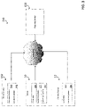
- FIG. 3 is a block diagram of an example system 350 for displaying a map of an area to be mowed by a robot lawnmower 10.
- the example system 350 includes the robot lawnmower 10, a mobile device 502, and a docking station 12.
- Those devices can communicate over a data communications network 158 with a mapping system 600 of one or more computers.
- the network 158 can include, e.g., a wireless router that communicates with the devices wirelessly and is connected to the Internet to communicate with the mapping system 600.
- the robot 10 and docking station 12 can communicate with the mobile device and the mobile device can relay information to the mapping system.
- the robot lawnmower 10 includes a controller 150, a detection system 160 configured to detect beacons, and an optional location system 152, e.g., a Global Positioning System (GPS) receiver.
- the mobile device 502 includes a processor system 510 and an optional location system 512, e.g., a GPS receiver.
- the docking station 12 in some implementations, can be a charging station that does not communicate on the network 158, and in some other implementations, can have a controller 154 and/or a location system 156, e.g., a GPS receiver.
- the robot lawnmower 10 traverses an area to be mowed.
- a human operator can push the robot lawnmower 10 around a perimeter of the area to be mowed, as described above with reference to FIGS. 1A-C .
- the robot controller 150 using the detection system, detects beacons while traversing the area and collects mapping data that specifies the perimeter of the area to be mowed.
- the robot lawnmower 10 After the robot lawnmower 10 collects the mapping data, the robot lawnmower 10 transmits the mapping data to the mobile device 502. For example, the robot lawnmower 10 can communicate with the mobile device 502 over a Bluetooth connection or over a local wireless network. The mobile device 502 can initiate the transmission by launching a mapping application executed by the processor system 510.
- the mobile device 502 receives at least two reference geographic coordinates for reference points within the area.
- the geographic coordinates include a latitude and a longitude.
- other geolocation data could be used.
- the reference points correspond to positions specified by the mapping data.
- the mobile device 502 can acquire the reference coordinates using any of various appropriate techniques. For purposes of illustration, consider the following three examples.
- the mobile device 502 will use its location system 512 to acquire the reference coordinates.
- the mobile device 502 in executing a mapping application, can instruct a human operator to move the mobile device 502 to the docking station 12, which can be a point specified in the mapping data by virtue of the robot lawnmower 10 starting at the docking station 12 while collecting the mapping data.
- the human operator provides input to the mobile device 502 indicating that the mobile device 502 is at the docking station, and the mobile device 502 uses its location system 512 to obtain a first geographic reference coordinate.
- the mobile device 502 instructs the human operator to move the mobile device 502 to another point in the area that is specified in the mapping data.
- the mobile device 502 can instruct the human operator to move the mobile device 502 to the closest beacon or to another beacon, or the mobile device 502 can instruct the human operator to walk a certain distance along the path taken while the robot lawnmower 10 was collecting the mapping data.
- the mobile device 502 uses its location system 512 to obtain the second geographic reference coordinate.
- the robot lawnmower 10 while collecting the mapping data, can also obtain the reference coordinates. For example, when the robot lawnmower 10 starts collecting the mapping data at the location of the docking station 12, the robot lawnmower 10 uses the location system 152 to obtain the first geographic reference coordinates (e.g., latitude and longitude coordinates). Then, after the robot lawnmower 10 moves to another location in the area that is at least a certain distance from the docking station 12, the robot lawnmower 10 uses the location system 152 to obtain additional geographic reference coordinates. This process can be repeated to obtain any number of additional geographic reference coordinates.
- the first geographic reference coordinates e.g., latitude and longitude coordinates
- the robot lawnmower 10 sends the mapping data and the geographic reference coordinates to the mobile device 502. In some cases, e.g., where the location of the reference points is not already specified, the robot lawnmower 10 can send data specifying how the geographic reference coordinates correspond to the mapping data.
- the docking station 12 has and uses a location system 156.
- the docking station 12 can supply the first geographic reference coordinates (e.g., latitude and longitude coordinates), and robot lawnmower 10 or the mobile device 502 can obtain the second geographic reference coordinates at a point at least a certain distance away from the docking station 12 within the area. It may be useful to have a location system 156 in the docking station 12 instead of the robot lawnmower 10, e.g., to reduce the weight of the robot lawnmower 10.
- the mobile device 502 uses the geographic reference coordinates and the mapping data to display a map image of the area to be mowed.
- the mobile device 502 obtains a map image from the mapping system 600, orients the mapping data to a coordinate system of the map image from the mapping system 600, and then displays the map image with a graphic overlay of the perimeter of the area to be mowed.
- the mobile device 502 sends the mapping data and the geographic reference coordinates to the mapping system 600, and the mapping system 600 generates a map image with a graphic overlay of the perimeter of the area to be mowed.
- the first geographic reference coordinate is used to identify a common location between the map image and the boundary and the second geographic reference is used to rotationally align the map image with the mapping data.
- FIGS. 4A-4K depict example map images and mapping data to illustrate the use of the system 350 of FIG. 3 .
- FIG. 4A depicts an example perimeter 450 of an area to be mowed.
- the perimeter 450 can be stored in any appropriate data structure, e.g., as a series of X,Y coordinates referenced in a coordinate system 454.
- the coordinates can be distances (e.g., X and Y distances) from a starting point, e.g., a docking station 12, of the robot lawnmower 10 when it was collecting mapping data.
- the mapping data can include the location of beacons 805 which can be illustrated with dots or other symbols.
- FIG. 4I illustrates the perimeter 450 as a Cartesian grid of cells that are marked as being inside, outside, or on the boundary of the mowable region.
- FIG. 4B depicts an example map image 452 of an area to be mowed.
- a mobile device 502 can obtain the map image 452 from a mapping system 600.
- the mapping system 600 may store map images or obtain map images from another system.
- the mobile device 502 provides location data to the mapping system 600.
- the mobile device 502 can send GPS coordinates to the mapping system, or the mobile device 502 can prompt a human operator 500 to enter an address.
- the map image 452 is displayed with reference to a coordinate system 456.
- FIG. 4C depicts the map image 452 with the perimeter 450 overlaid on top of the map image 452.
- the perimeter 450 has not been adjusted to account for the different coordinate system 456. Consequently, the perimeter 450 does not accurately depict the boundary of the area to be mowed with respect to the map image 452.
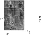
- FIG. 4D depicts the map image 452 with the perimeter 450 overlaid after the mapping data has been adjusted to account for the different coordinate systems 454, 456.
- the mobile device 502 and/or the mapping system 600 can adjust the mapping data by shifting, rotating, and/or scaling the mapping data so that the mapping data is aligned to the coordinate system of the map image 452. When aligned, the geographic coordinates of the reference points within the mapping data will match with geographic coordinates for the map image.
- the perimeter path 450 is translated to the same coordinate frame as the map image 452.
- the difference between the first reference point location in the robot coordinate system 454 and the first reference point location in the image coordinate system 456 is calculated. All data within the robot coordinate system 454, including beacon locations 805 and the perimeter path 450, can be shifted by that difference, resulting in translated data.
- the first reference point in the image coordinate system can be used as the vertex to calculate the angle between the second reference point from the translated robot coordinate system 454 and the second reference point from the image coordinate system 456. This angle can used to rotate all data in the translated data in the image coordinate system.
- FIG. 4E depicts an example screenshot of the displayed map image 460 with a user interface element 462 requesting a user to confirm the location of the boundary on the map image.
- the user can inspect the map image 460 to confirm that the perimeter 450 was correctly captured by the robot lawnmower 10 and/or that the perimeter 450 has been correctly aligned to the map image 460. Because the map image 460 is for user perception of the boundary and mowing location/progress and is not used to control or identify the boundary for the robot lawnmower 10, it is not necessary for the alignment to be exact. More particularly, the robot determines its location relative to the trained boundary using the coordinate system defined during the training process.
- FIG. 4F depicts an example screenshot of the displayed map image 460 with a graphic overlay 466 showing the progress of the robot lawnmower 10 as it mows the lawn. More particularly, the robot sends information about its location during mowing to the mobile device and the mobile device 502 updates the map with the graphic overlay showing the path traversed by the robot 10.
- the map image 460 also includes a user interface element 464 depicting an estimated time to completion. The time to completion can be estimated based on, e.g., the area remaining to be mowed within the perimeter 450 of the area to be mowed.
- the user interface element 464 can be any appropriate user interface element.
- FIG. 4G depicts an example screenshot of the displayed map image 460 with a graphic overlay 468 showing a graphic overlay 466 showing the progress of the robot lawnmower 10 and a projected remaining path of the robot lawnmower 10 as it mows the lawn.
- the projected path can be projected, e.g., based on the shape of the perimeter 450 and the current progress of the robot lawnmower 10. Projecting the remaining path of the robot lawnmower 10 is described in further detail below with reference to FIG. 6 .
- the robot lawnmower 10 can encounter unexpected obstacles during the mowing process.
- a tree limb could block the robot lawnmower 10 from mowing a particular location or area of the yard.
- an indicator (not shown) can be provided on the display at the location where the unexpected obstacle was encountered. This can provide an indication to the user (e.g., the homeowner) that he/she should remove an obstacle from the yard to allow the robot lawnmower 10 to traverse the area and mow the area during its next scheduled mowing time.
- FIG. 4H depicts an example screenshot of the displayed map image 460 with a suggested location 470 of a beacon.
- the suggested location 470 can be an alternative to an existing location of a beacon. Because users may choose their own beacon locations, it can be useful to provide suggested locations for beacons with reference to a map image 460 to help show users where beacon placement may improve performance factors (e.g., accuracy, efficiency) of the robot lawnmower 10. Determining suggested beacon locations is described in further detail below with reference to FIG. 7 .
- FIG. 5 is a flow diagram of an example method 5000 performed by a computing device, e.g., mobile device 502, for displaying a map image of an area to be mowed.
- a computing device e.g., mobile device 502
- the mobile device 502 can perform the method, for example, to produce the screen shots of FIGS. 4D-4H .
- the mobile device 502 can begin performing the method 5000 when a user launches a mapping application on the mobile device 502.
- the mobile device 502 initializes communication with the robot lawnmower 10 (5002). For example, the mobile device 502 can establish a Bluetooth connection with the robot lawnmower 10, or the mobile device 502 can connect with the robot lawnmower 10 over a wireless network. In some implementations, the mobile device 502 prompts a user for information to correctly identify the robot lawnmower 10; in some other implementations, the mobile device 502 is configured to wirelessly probe for the robot lawnmower 10. In some implementations, the controller 150 of the robot lawnmower 10 authenticates to the mobile device 502.
- the mobile device 502 can prompt the user to cause the robot lawnmower 10 to collect the mapping data.
- the mobile device 502 can display instructions for the user to interact with robot lawnmower 10, and the mobile device 502 can place a phone call to a customer service department if the user desires to get help from a person.
- the user pushes the robot lawnmower 10 about the yard, e.g., as described above with reference to FIGS. 1A-C .
- the mobile device 502 receives the mapping data from the robot lawnmower 10 (5004).
- the mapping data can define a perimeter of the area to be mowed and other data, e.g., locations of beacons placed about the area to be mowed.
- the mapping data can be stored in any appropriate data structure, e.g., as a list of coordinates with respect to a starting point, or as vector data.
- the mobile device 502 receives geographic coordinates of reference points within the area (5006).
- the mobile device 502 can receive the geographic coordinates of reference points as described above with reference to FIG. 3 .
- the mobile device 502 receives geographic coordinates for at least two reference points.
- the reference points can be, e.g., the location of a docking station 12 and a nearest beacon 850 or other point at least a certain distance away from the docking station 12.
- the mobile device 502 receives a map image of the area to be mowed (5007).
- the mobile device 502 can use one of the reference points (e.g., the latitude and longitude) to retrieve the map image from a database of map images.
- the mobile device can request that the user enter an address and use the address to retrieve the map image from the database of map images.
- the received map image can be an overhead photograph of the lawn and surrounding image such as a satellite image.
- the mobile device 502 aligns the mapping data to a coordinate system of a map image of the area to be mowed (5008). For example, the mobile device 502 can obtain the map image and data associated with the map image that specifies a correspondence between portions of the map image and geographic coordinates. The mobile device can then align the mapping by data by shifting, rotating, and/or scaling the mapping data so that the first and second reference points match first and second locations on the map image as specified by the data specifying the correspondence between portions of the map image and geographic coordinates.
- the mobile device 502 and/or the mapping system can search for features in the map that correspond with the perimeter 450.
- Image classifiers can be used on the map image 452 to find commonly traced features, such as the corner of a house or building, the edge of a lawn, or any other distinct path that matches well with the perimeter 450.
- the mobile device 502 can also incorporate other sources of information with the same geodetic coordinate system as the map image 452, such as public boundary and property lines.
- the robot 10 can include directional data with the mapping data.
- the mobile device 502 and/or the mapping system can then use the directional data, e.g., instead of one of the reference points or in addition to the two reference points to improve the alignment.
- the robot 10 can include, with the mapping data, data indicating which direction is north.
- the mapping system can also then determine which direction, for the map image, faces north, and the mobile device 502 and/or the mapping system can align the mapping data and/or the map image so that the two directions match.
- image registration techniques from computer vision are used to align the map data with the map image.
- the map is converted to a grid representation (if it is not already in that format), where each cell is marked as either inside or outside the mowable region, and each cell value can be represented by a pixel with a different intensity.
- mowable cells can be marked by white pixels and non-mowable cells can be marked by black pixels.
- the map image is also processed by an algorithm that converts colors to intensities based on the probability that each color corresponds to a mowable region. For example, green pixels may be converted to white pixels (high likelihood of being mowable), yellow and brown pixels may be converted to gray pixels (medium likelihood of being mowable), and pixels of other colors may be converted to black pixels (low likelihood of being mowable.
- a machine learning algorithm e.g. support vector machine, neural network
- the machine learning algorithm can then be used with the map image to create two grass probability images (GPIs), one for the mowable area and one for the map image, can then be aligned using standard image registration techniques.
- FIG. 4J illustrates an example grass probability image 480 for the mowable area.
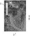
- FIG. 4K illustrates an example grass probability image 482 for the map image.
- These techniques can include intensity-based algorithms and feature-based algorithms.
- the georeferenced points measured using, e.g., GPS on the robot 10, dock 12, or mobile device 502 can be used as an initial guess of the alignment between the map GPI and the map image GPI.
- the map GPI is then transformed (using translation and rotation) and correlated with the map image GPI, and the transformation with the highest correlation value is used to align the images.
- the search of transformation space can either be exhaustive in a limited region near the initial guess, or non-linear optimization techniques such as hill climbing, gradient descent, or simulated annealing can be used to reduce the time required for alignment.
- a feature-based approach local features are detected in the map GPI and the map image GPI. These features can include lines and corners, as well as scale-invariant features such as SIFT (Scale-Invariant Feature Transform), SURF (Speeded Up Robust Features), or HOG (Histogram of Oriented Gradients).
- SIFT Scale-Invariant Feature Transform
- SURF Speeded Up Robust Features
- HOG Histogram of Oriented Gradients
- the mobile device 502 receives the map image from a mapping system 600 and aligns the mapping data to the map image. In some other implementations, the mobile device 502 supplies the mapping data and geographic coordinates for the reference points to the mapping system 600, and the mapping system aligns the mapping data and supplies a map image using the aligned mapping data.
- the mapping system can select the map image in any appropriate way, e.g., using the geographic coordinates for the reference points, or by using the user's street address.
- the mobile device 502 displays the map image using the aligned mapping data (5010).
- the mobile device 502 can display the map image with a graphic overlay illustrating a perimeter of the area to be mowed.
- the mobile device 502 can display the map image with the area to be mowed highlighted or shaded.
- the map image and the mapping data can be used for various optional tasks (5012).
- the mobile device 502 can prompt the user to confirm the area to be mowed.
- the mobile device 502 can present a display that shows the progress of the robot lawnmower 10 in real-time or near real-time while it is mowing the lawn, e.g., by having the robot lawnmower 10 communicate its position to the mobile device 502 while it mows the lawn.
- the mobile device 502 can present a display that shows the projected remaining path of the robot lawnmower 10 and/or the projected time remaining for the robot lawnmower 10 to complete mowing the lawn.
- FIG. 6 is a flow chart of an example method 6000 for projecting the remaining path of a robot lawnmower 10.
- the method 6000 is performed by a computing device, e.g., the mobile device 502 of FIG. 3 .
- the method 6000 will be described as being performed by the mobile device 502 of FIG. 3 .
- the mobile device 502 receives mapping data defining a perimeter around the area to be mowed (6002).
- the mobile device 502 receives tracking data specifying a portion of the area that the robot lawnmower 10 has already mowed (6004).
- the mobile device 502 plots a projected path for the robot lawnmower 10 from the robot lawnmower's current location that could be followed by the robot lawnmower 10 to finish mowing the area inside of the perimeter that has not been mowed (6006). In some implementations, the mobile device 502 plots the projected path by simulating a navigational algorithm stored on the controller 150 of the robot lawnmower 10.
- the controller generates a coverage path based on a Boustrephedon (e.g., cornrow) algorithm applied to a grid map representation of the lawn.
- a Boustrephedon e.g., cornrow
- the robot may start at one corner of the lawn (as in the example in FIG. 4F ), and then move parallel to the lawn edge until it encounters a lawn boundary cell. At this point the robot makes a 180 degree turn and then mows down a new path that is parallel to the first row, and offset laterally by no more than the width of the cutting mechanism (to insure that there is no gap between the cut grass in each row).
- the user could also select the orientation of these ranks (vertical, horizontal, or an arbitrary angle as preferred by them).
- the user can also block off an area of the lawn that they would like the robot lawnmower to not cover during its current mission or designate an area that should be more thoroughly mowed (by way of slower movement or multiple passes).
- the boundary of this "keep-out" zone are marked in the grid map as boundary cells, while the cells inside the keep-out zone are marked as non-mowable.
- Paths can have other configurable metrics that allows the user to select between different mow patterns or styles or can have pseudo-random attributes that allow for varying paths to be generated.
- the mobile device 502 generates a map image of the area to be mowed with a graphic overlay of the projected path (6008).
- the mobile device can align the mapping data and the tracking data to a coordinate system of a map image, e.g., as described further above with reference to FIG. 5 .
- the mobile device can include various features in the map image, e.g., a first graphic overlay showing the area that the robot lawnmower 10 has already mowed and a second graphic overlay showing the projected path and an indicator of a projected time to completion.
- the projected time to completion can be based on, e.g., the size of the area remaining to be mowed and a speed of the robot lawnmower 10 and the amount of overlap between the rows/ranks.
- the time remaining may also be based on the amount of battery that the robot lawnmower 10 has left and can be calculated by the amount of energy left in the battery and/or the amount of energy left in the battery less the energy required to get the robot lawnmower 10 back to the docking station 12 divided by the average power consumption.
- the total time remaining to mow the lawn can also be displayed, including the time required to return to the charger, recharge, and then mow the remaining area.
- FIG. 7 is a flow chart of an example method 7000 for determining suggested beacon locations.
- the method 7000 is performed by a computing device, e.g., the mapping system 600 of FIG. 3 .
- the method 7000 will be described as being performed by the mapping system 600 of FIG. 3 .
- the mapping system 600 receives mapping data defining a perimeter of an area to be mowed (7002).
- the mapping data also specifies the locations of several navigation beacons.
- the mapping system 600 receives the mapping data from the robot lawnmower 10.
- the robot lawnmower 10 can provide the mapping data to the mobile device 502, which can then provide the mapping data to the mapping system 600, e.g., at the request of a user.
- the mapping system 600 checks each beacon location for a possible suggested location (7004). For example, the mapping system can determine, for each beacon, the distance to the two nearest beacons. If the beacon is closer to one of the nearest beacons than the other, the mapping system can determine a suggested location that is closer to a mid-point between the two beacons along the perimeter. In another example, the mapping system can use elevation data to determine that two neighboring beacons are at two different elevations with a height distance that exceeds a threshold. The mapping system can determine a suggested location that is at an elevation between the two different elevations.
- the robot lawnmower 10 can identify places where position estimates from the localization system are less confident.
- the mapping system can suggest placing a beacon near these places of lower confidence. Suggested locations can also be based on the beacon location map by analyzing long gaps in distance between beacons or beacons that are only able to communicate with a couple beacons because of occlusions.
- the mapping system 600 provides any suggested beacon locations for display on a map image (7006).
- the mapping system 600 can generate a map image, by aligning the mapping data to a map image, with graphic indicators of the current beacon locations and the suggested beacon locations.
- the mapping system 600 provides the suggested locations to a mobile device 502, and the mobile device 502 generates a map image showing the suggested beacon locations.
Landscapes
- Engineering & Computer Science (AREA)
- Radar, Positioning & Navigation (AREA)
- Remote Sensing (AREA)
- Physics & Mathematics (AREA)
- General Physics & Mathematics (AREA)
- Automation & Control Theory (AREA)
- Aviation & Aerospace Engineering (AREA)
- Electromagnetism (AREA)
- Life Sciences & Earth Sciences (AREA)
- Environmental Sciences (AREA)
- General Engineering & Computer Science (AREA)
- Optics & Photonics (AREA)
- Health & Medical Sciences (AREA)
- Game Theory and Decision Science (AREA)
- Medical Informatics (AREA)
- Evolutionary Computation (AREA)
- Artificial Intelligence (AREA)
- Business, Economics & Management (AREA)
- Computer Networks & Wireless Communication (AREA)
- Control Of Position, Course, Altitude, Or Attitude Of Moving Bodies (AREA)
- Guiding Agricultural Machines (AREA)
- Harvester Elements (AREA)
Claims (15)
- Système de tondeuse à gazon robotisée comprenant :une pluralité de balises (805) positionnées par rapport à une zone à tondre (20);une tondeuse robotisée (10) comprenant :un système de détection (160) configuré pour détecter les balises (805); etun contrôleur (150) configuré pour, lors de la traversée de la zone à tondre (20), détecter les balises (805) à l'aide du système de détection (160) et recueillir des données cartographiques ;un ou plusieurs supports lisibles par ordinateur stockant des instructions qui, à leur exécution par un système d'un ou de plusieurs dispositifs informatiques, amènent le système à réaliser des opérations comprenant :la réception des données cartographiques à partir de la tondeuse robotisée (10);la réception au moins de premières et deuxièmes coordonnées géographiques de premier et deuxième points de référence qui se trouvent dans la zone (20) et qui sont spécifiés dans les données cartographiques ;l'alignement des données cartographiques conformément à un système de coordonnées (456) d'une image cartographique (452) de la zone (20) à l'aide des premières et deuxièmes coordonnées géographiques,caractérisé en quel'alignement des données cartographiques conformément au système de coordonnées (456) de l'image cartographique (452) comprend une ou plusieurs des opérations suivantes : déplacement, rotation et mise à l'échelle des données cartographiques de telle sorte que des premier et deuxième emplacements sur l'image cartographique (452) de la zone (20) correspondent aux premier et deuxième points de référence ; etl'affichage de l'image cartographique (452) de la zone (20) en fonction de l'alignement des données cartographiques conformément au système de coordonnées (456).
- Système de tondeuse à gazon robotisée selon la revendication 1, les opérations comprenant la configuration du contrôleur (150) de la tondeuse robotisée (10) pour tondre la zone de manière autonome (20).
- Système de tondeuse à gazon robotisée selon l'une quelconque des revendications précédentes, dans lequel la tondeuse à gazon robotisée (10) comprend un récepteur de système de positionnement global (GPS) (152) et dans lequel le contrôleur (150) est configuré pour déplacer la tondeuse à gazon robotisée (10) jusqu'aux premier et deuxième points de référence dans la zone (20) et déterminer les premières et deuxièmes coordonnées géographiques des premier et deuxième points de référence à l'aide du récepteur GPS (152) aux premier et deuxième points de référence.
- Système de tondeuse à gazon robotisée selon l'une quelconque des revendications précédentes, dans lequel le système d'un ou plusieurs dispositifs informatiques comprend un dispositif mobile (502), le dispositif mobile (502) comprend un récepteur de système de positionnement global (GPS) (512), et dans lequel la réception des premières et deuxièmes coordonnées géographiques des premier et deuxième points de référence comprend :l'affichage d'instructions à l'intention d'un utilisateur pour déplacer le dispositif mobile (502) jusqu'au premier point de référence ;en réponse à la réception d'une entrée de l'utilisateur indiquant que le dispositif mobile (502) se trouve au premier point de référence, la détermination des premières coordonnées géographiques à l'aide du récepteur GPS (512) ;l'affichage d'instructions à l'intention d'un utilisateur pour déplacer le dispositif mobile (502) jusqu'au deuxième point de référence ; eten réponse à la réception d'une entrée de l'utilisateur indiquant que le dispositif mobile (502) se trouve au deuxième point de référence, la détermination des deuxièmes coordonnées géographiques à l'aide du récepteur GPS (512).
- Système de tondeuse à gazon robotisée selon l'une quelconque des revendications 1 à 3, comprenant une station d'accueil (12) pour la tondeuse robotisée (10) au premier ou deuxième point de référence.
- Système de tondeuse à gazon robotisée selon la revendication 5, dans lequel:la tondeuse robotisée (10) comprend un premier récepteur GPS (152) ;la station d'accueil (12) comprend un second récepteur GPS (156) ;la réception des premières coordonnées géographiques comprend la réception des premières coordonnées géographiques à partir de la tondeuse robotisée (10) à l'aide du premier récepteur GPS (152) ; et la réception des deuxièmes coordonnées géographiques comprend la réception des deuxièmes coordonnées géographiques à partir de la station d'accueil (12) à l'aide du second récepteur GPS (156), ou dans lequel :la station d'accueil (12) comprend un premier récepteur de système de positionnement global (GPS) (156) ;le système d'un ou plusieurs dispositifs informatiques comprend un dispositif mobile (502) qui comprend un second récepteur GPS (512) ;la réception des premières coordonnées géographiques comprend la réception des premières coordonnées géographiques à partir de la station d'accueil (12) à l'aide du premier récepteur GPS (156) ; et la réception des deuxièmes coordonnées géographiques comprend la réception des deuxièmes coordonnées géographiques à partir du dispositif mobile (502) à l'aide du deuxième récepteur GPS (512).
- Système de tondeuse à gazon robotisée selon l'une quelconque des revendications précédentes, dans lequel :le système d'un ou plusieurs dispositifs informatiques comprend un dispositif mobile (502) ;la réception des données cartographiques à partir de la tondeuse à gazon robotisée (10) comprend la réception des données cartographiques par l'intermédiaire d'une liaison de communication filaire ou sans fil entre la tondeuse robotisée (10) et le dispositif mobile (502) ; etl'alignement des données cartographiques conformément à un système de coordonnées (456) de l'image cartographique (452) comprend la fourniture des données cartographiques à un système de serveur cartographique (600) d'un ou plusieurs ordinateurs et la réception de l'image cartographique (452) à partir du système de serveur cartographique (600).
- Système de tondeuse à gazon robotisée selon l'une quelconque des revendications précédentes, dans lequel les données cartographiques comportent un chemin de tonte, et dans lequel l'affichage de l'image cartographique (452) comprend l'affichage de l'image cartographique (452) avec un indicateur visuel superposé du chemin de tonte.
- Système de tondeuse à gazon robotisée selon la revendication 8, dans lequel l'affichage de l'image cartographique (452) comprend l'affichage d'indicateurs de balises d'emplacements des balises (805) dans la zone (20) à l'aide des données cartographiques.
- Système de tondeuse à gazon robotisée selon l'une quelconque des revendications précédentes, les opérations comprenant :la fourniture des données cartographiques et des premières et deuxièmes coordonnées géographiques des premier et deuxième points de référence à un système de serveur distant (600) d'un ou plusieurs ordinateurs ;la réception, à partir du système de serveur distant (600), d'une ou plusieurs positions suggérées (470) dans la zone (20) pour les balises (805) ; etl'affichage, sur l'image cartographique, d'indicateurs des positions suggérées (470) pour les balises (805).
- Système de tondeuse à gazon robotisée selon l'une quelconque des revendications 1 à 9, les opérations comprenant :pour au moins une balise (805), la détermination de première et deuxième distances jusqu'à des première et deuxième balises voisines les plus proches (805) de l'au moins une balise (805) ;la détermination qu'une différence entre les première et deuxième distances est supérieure à une distance seuil ;la détermination d'un emplacement de balise suggéré (470) pour l'au moins une balise (805) à mi-chemin entre les première et deuxièmes balises voisines les plus proches (805) le long d'un périmètre (450) de la zone à tondre (20) ; etl'affichage, sur l'image cartographique (452), d'un indicateur de l'emplacement de balise suggéré (470) de l'au moins une balise (805).
- Système de tondeuse à gazon robotisée selon l'une quelconque des revendications précédentes, les opérations comprenant :la réception de données de suivi à partir de la tondeuse à gazon robotisée (10) pendant que la tondeuse robot (10) tond la zone (20) ; etl'affichage, sur l'image cartographique (452), d'un calque graphique (466) indiquant la progression de la tondeuse robotisée (10).
- Système de tondeuse à gazon robotisée selon la revendication 12, les opérations comprenant :la projection d'un chemin de la tondeuse robotisée (10) jusqu'à l'achèvement de la tonte de la zone (20) ; etl'affichage, sur la carte, d'un claque graphique (468) indiquant la trajectoire projetée de la tondeuse robotisée (10).
- Système de tondeuse à gazon robotisée selon la revendication 12 ou selon la revendication 13, les opérations comprenant :
l'affichage d'un élément d'interface utilisateur (464) indiquant un délai estimé jusqu'à l'achèvement. - Procédé d'affichage d'une image cartographique (452) d'une zone à tondre (20) réalisé par un système d'un ou plusieurs dispositifs informatiques, le procédé comprenant:la réception de données cartographiques à partir d'une tondeuse robotisée (10), les données cartographiques spécifiant la zone à tondre (20) et une pluralité d'emplacements de balises (805) positionnées dans la zone à tondre (20) ;la réception au moins de premières et deuxièmes coordonnées géographiques de premier et deuxième points de référence qui se trouvent dans la zone (20) et qui sont spécifiés dans les données cartographiques ;l'alignement des données cartographiques conformément à un système de coordonnées (456) de l'image cartographique (452) de la zone (20) à l'aide des premières et deuxièmes coordonnées géographiques ; et caractérisé en ce que le procédé comprend en outre :l'affichage de l'image cartographique (452) de la zone (20) en fonction de l'alignement des données cartographiques conformément au système de coordonnées (456), eten ce que:
l'alignement des données cartographiques conformément au système de coordonnées (456) de l'image cartographique (452) comprend une ou plusieurs des opérations suivantes : déplacement, rotation et mise à l'échelle des données cartographiques de telle sorte que des premier et deuxième emplacements de l'image cartographique (452) de la zone (20) correspondent aux premier et deuxième points de référence.
Applications Claiming Priority (2)
| Application Number | Priority Date | Filing Date | Title |
|---|---|---|---|
| US14/570,616 US9420741B2 (en) | 2014-12-15 | 2014-12-15 | Robot lawnmower mapping |
| PCT/US2015/050477 WO2016099616A1 (fr) | 2014-12-15 | 2015-09-16 | Mappage pour tondeuse à gazon robotisée |
Publications (2)
| Publication Number | Publication Date |
|---|---|
| EP3232762A1 EP3232762A1 (fr) | 2017-10-25 |
| EP3232762B1 true EP3232762B1 (fr) | 2022-11-23 |
Family
ID=54207785
Family Applications (1)
| Application Number | Title | Priority Date | Filing Date |
|---|---|---|---|
| EP15771412.2A Active EP3232762B1 (fr) | 2014-12-15 | 2015-09-16 | Mappage pour tondeuse à gazon robotisée |
Country Status (4)
| Country | Link |
|---|---|
| US (3) | US9420741B2 (fr) |
| EP (1) | EP3232762B1 (fr) |
| CN (1) | CN106662452B (fr) |
| WO (1) | WO2016099616A1 (fr) |
Cited By (1)
| Publication number | Priority date | Publication date | Assignee | Title |
|---|---|---|---|---|
| US20210116933A1 (en) * | 2011-08-11 | 2021-04-22 | Chien Ouyang | Mapping and tracking system for robots |
Families Citing this family (177)
| Publication number | Priority date | Publication date | Assignee | Title |
|---|---|---|---|---|
| US20170325400A1 (en) * | 2012-11-12 | 2017-11-16 | Ariel Scientific Innovations Ltd | Method for navigation and joint coordination of automated devices |
| US10149430B2 (en) * | 2013-02-20 | 2018-12-11 | Husqvarna Ab | Robotic work tool configured for improved turning in a slope, a robotic work tool system, and a method for use in the robot work tool |
| AU2013402725B2 (en) * | 2013-10-07 | 2018-04-12 | Apple Inc. | Method and system for providing position or movement information for controlling at least one function of a vehicle |
| US10937187B2 (en) | 2013-10-07 | 2021-03-02 | Apple Inc. | Method and system for providing position or movement information for controlling at least one function of an environment |
| CN105446350B (zh) * | 2014-09-26 | 2018-05-29 | 科沃斯机器人股份有限公司 | 自移动机器人移动界限划定方法 |
| US10188029B1 (en) | 2014-10-20 | 2019-01-29 | Hydro-Gear Limited Partnership | Method of generating a three-dimensional map of a lawn and its use to improve mowing efficiency |
| US9420741B2 (en) * | 2014-12-15 | 2016-08-23 | Irobot Corporation | Robot lawnmower mapping |
| EP3971672A1 (fr) | 2014-12-17 | 2022-03-23 | Husqvarna AB | Véhicule robotisé autonome à capteurs multiples ayant une capacité cartographique |
| EP3234718B1 (fr) * | 2014-12-17 | 2018-10-24 | Husqvarna AB | Véhicule robotique apprentissant la délimitation du terrain |
| WO2016097896A1 (fr) * | 2014-12-18 | 2016-06-23 | Husqvarna Ab | Cartographie de parcelles par détection de résistance électrique d'un véhicule robotisé |
| WO2016103067A1 (fr) * | 2014-12-22 | 2016-06-30 | Husqvarna Ab | Cartographie et planification d'un jardin par l'intermédiaire d'un véhicule robotisé |
| US9538702B2 (en) * | 2014-12-22 | 2017-01-10 | Irobot Corporation | Robotic mowing of separated lawn areas |
| US11112532B2 (en) * | 2014-12-27 | 2021-09-07 | Husqvarna Ab | Weather collection and aggregation via robotic vehicle |
| US9588519B2 (en) * | 2015-03-17 | 2017-03-07 | Amazon Technologies, Inc. | Systems and methods to facilitate human/robot interaction |
| US9649766B2 (en) | 2015-03-17 | 2017-05-16 | Amazon Technologies, Inc. | Systems and methods to facilitate human/robot interaction |
| JP5973609B1 (ja) * | 2015-03-27 | 2016-08-23 | 本田技研工業株式会社 | 無人作業車の制御装置 |
| JP6038990B2 (ja) * | 2015-03-27 | 2016-12-07 | 本田技研工業株式会社 | 無人作業車の制御装置 |
| DE102015109775B3 (de) | 2015-06-18 | 2016-09-22 | RobArt GmbH | Optischer Triangulationssensor zur Entfernungsmessung |
| EP3693827A1 (fr) * | 2015-06-26 | 2020-08-12 | Positec Power Tools (Suzhou) Co., Ltd | Dispositif mobile autonome et son système de charge sans fil |
| US9828094B2 (en) * | 2015-07-26 | 2017-11-28 | John B. McMillion | Autonomous cleaning system |
| DE102015114883A1 (de) | 2015-09-04 | 2017-03-09 | RobArt GmbH | Identifizierung und Lokalisierung einer Basisstation eines autonomen mobilen Roboters |
| US9594151B1 (en) * | 2015-09-05 | 2017-03-14 | Techip International Limited | System and method for locating objects |
| DE102015119501A1 (de) | 2015-11-11 | 2017-05-11 | RobArt GmbH | Unterteilung von Karten für die Roboternavigation |
| DE102015119865B4 (de) | 2015-11-17 | 2023-12-21 | RobArt GmbH | Robotergestützte Bearbeitung einer Oberfläche mittels eines Roboters |
| DE102015121666B3 (de) | 2015-12-11 | 2017-05-24 | RobArt GmbH | Fernsteuerung eines mobilen, autonomen Roboters |
| EP3187953B1 (fr) * | 2015-12-30 | 2020-03-18 | Honda Research Institute Europe GmbH | Machine de travail autonome telle qu'une tondeuse à gazon autonome |
| SG11201805378XA (en) * | 2016-01-04 | 2018-07-30 | Zhejiang Libiao Robots Co Ltd | Method and device for returning robots from site |
| WO2017123761A1 (fr) * | 2016-01-15 | 2017-07-20 | Irobot Corporation | Contrôle autonome de systèmes robotiques |
| US10335949B2 (en) * | 2016-01-20 | 2019-07-02 | Yujin Robot Co., Ltd. | System for operating mobile robot based on complex map information and operating method thereof |
| DE102016102644A1 (de) | 2016-02-15 | 2017-08-17 | RobArt GmbH | Verfahren zur Steuerung eines autonomen mobilen Roboters |
| JP6212590B2 (ja) * | 2016-03-31 | 2017-10-11 | 本田技研工業株式会社 | 自律走行作業車の制御装置 |
| EP3439522B1 (fr) * | 2016-04-08 | 2023-06-07 | A&K Robotics Inc. | Autolaveuse convertible entre un fonctionnement à commande manuelle et un fonctionnement autonome |
| US10386839B2 (en) * | 2016-05-26 | 2019-08-20 | Boston Incubator Center, LLC | Mobile robot that emulates pedestrian walking behavior |
| US10111381B2 (en) | 2016-06-28 | 2018-10-30 | The Toro Company | Walk power mower with transmission providing both forward and reverse propulsion |
| WO2018024897A1 (fr) | 2016-08-05 | 2018-02-08 | RobArt GmbH | Procédé de commande d'un robot mobile autonome |
| GB2556036A (en) * | 2016-11-03 | 2018-05-23 | Fleet Line Markers Ltd | Service vehicle and management system |
| WO2018086612A1 (fr) * | 2016-11-11 | 2018-05-17 | 苏州宝时得电动工具有限公司 | Système de travail automatique et procédé de commande correspondant |
| US10723018B2 (en) | 2016-11-28 | 2020-07-28 | Brain Corporation | Systems and methods for remote operating and/or monitoring of a robot |
| EP4276645A3 (fr) * | 2016-12-15 | 2024-01-10 | Positec Power Tools (Suzhou) Co., Ltd. | Méthode de détection d'état pour système de travail automatique et station mobile |
| KR20180079962A (ko) | 2017-01-03 | 2018-07-11 | 삼성전자주식회사 | 로봇 청소기 및 그 제어 방법 |
| EP3571561B1 (fr) * | 2017-01-19 | 2022-03-02 | Husqvarna AB | Programme de travail amélioré pour tondeuse à gazon robotisée |
| US10852730B2 (en) * | 2017-02-08 | 2020-12-01 | Brain Corporation | Systems and methods for robotic mobile platforms |
| JP2020509500A (ja) | 2017-03-02 | 2020-03-26 | ロブアート ゲーエムベーハーROBART GmbH | 自律移動ロボットの制御方法 |
| JP6707481B2 (ja) * | 2017-03-03 | 2020-06-10 | ヤンマーパワーテクノロジー株式会社 | 作業画面表示システム |
| CN106843229B (zh) * | 2017-03-24 | 2020-11-10 | 上海思岚科技有限公司 | 用于移动设备的虚拟轨道设计系统及其实现方法 |
| EP3381257B1 (fr) | 2017-03-28 | 2020-12-02 | Honda Research Institute Europe GmbH | Procédé pour générer une représentation d'une zone de travail d'une tondeuse à gazon autonome et système de tondeuse à gazon autonome |
| US12108701B2 (en) | 2017-03-29 | 2024-10-08 | The Toro Company | Walk power mower with transmission providing both forward and reverse propulsion |
| US10489663B2 (en) * | 2017-04-24 | 2019-11-26 | Toyota Research Institute, Inc. | Systems and methods for identifying changes within a mapped environment |
| DE102017109219A1 (de) | 2017-04-28 | 2018-10-31 | RobArt GmbH | Verfahren für die Roboternavigation |
| US11582903B1 (en) | 2017-05-17 | 2023-02-21 | Hydro-Gear Limited Partnership | Vision based guidance system and method for lawn mowing devices |
| IT201700058505A1 (it) * | 2017-05-30 | 2018-11-30 | Volta Robots S R L | Metodo di controllo di un mezzo di lavorazione del terreno sulla base di elaborazioni d'immagini e relativo sistema |
| EP3413424B1 (fr) * | 2017-06-09 | 2020-12-23 | Andreas Stihl AG & Co. KG | Procédé de détermination d'une information destinée au fonctionnement d'un accumulateur, procédé de détermination de durées de charge de différents accumulateurs et système d'appareil forestier et/ou de jardin électrique |
| US10606267B2 (en) | 2017-06-19 | 2020-03-31 | International Business Machines Corporation | Weather based object protection using drones |
| CN107390686A (zh) * | 2017-07-17 | 2017-11-24 | 深圳拓邦股份有限公司 | 一种割草机器人控制方法及自动控制割草系统 |
| DE102017117148A1 (de) * | 2017-07-28 | 2019-01-31 | RobArt GmbH | Magnetometer für die roboternavigation |
| CN107550399B (zh) * | 2017-08-17 | 2021-05-18 | 北京小米移动软件有限公司 | 定时清扫方法及装置 |
| US10317220B2 (en) * | 2017-08-30 | 2019-06-11 | Aptiv Technologies Limited | Alignment of multiple digital maps used in an automated vehicle |
| CN107368079B (zh) * | 2017-08-31 | 2019-09-06 | 珠海市一微半导体有限公司 | 机器人清扫路径的规划方法及芯片 |
| KR101929129B1 (ko) * | 2017-09-12 | 2018-12-13 | 경일대학교산학협력단 | 농업용 무인 비행 장치 및 그 제어 방법 |
| US20190129442A1 (en) * | 2017-10-30 | 2019-05-02 | Sphero, Inc. | Magnetic robot calibration |
| CN107976998A (zh) * | 2017-11-13 | 2018-05-01 | 河海大学常州校区 | 一种割草机器人地图创建与路径规划系统及方法 |
| EP3698618B1 (fr) * | 2017-11-16 | 2022-01-05 | Nanjing Chervon Industry Co., Ltd. | Système intelligent de tondeuse à gazon |
| WO2019099253A1 (fr) * | 2017-11-20 | 2019-05-23 | The Toro Company | Système et procédé de fonctionnement d'une machine de travail robotique autonome à l'intérieur d'une zone de confinement de déplacement |
| EP3713720A4 (fr) | 2017-11-21 | 2021-08-18 | Service Robotics & Technologies, Inc. | Structure à base de cartes pour l'intégration de robots et de dispositifs intelligents |
| CN107807651B (zh) * | 2017-11-29 | 2021-02-19 | 北京康力优蓝机器人科技有限公司 | 一种移动机器人的自充电控制系统和方法 |
| KR102070068B1 (ko) | 2017-11-30 | 2020-03-23 | 엘지전자 주식회사 | 이동 로봇 및 그 제어방법 |
| KR102060715B1 (ko) * | 2017-11-30 | 2019-12-30 | 엘지전자 주식회사 | 이동 로봇 및 그 제어방법 |
| US10638906B2 (en) * | 2017-12-15 | 2020-05-05 | Neato Robotics, Inc. | Conversion of cleaning robot camera images to floorplan for user interaction |
| JP6877330B2 (ja) | 2017-12-27 | 2021-05-26 | 株式会社クボタ | 自律走行型作業機のための作業領域決定システム、自律走行型作業機、および、作業領域決定プログラム |
| CN108040582A (zh) * | 2018-01-26 | 2018-05-18 | 武汉理工大学 | 一种基于dgps的自动循迹电动割草机 |
| KR102090649B1 (ko) * | 2018-02-28 | 2020-03-18 | 엘지전자 주식회사 | 이동로봇과 이동로봇 시스템 |
| EP3761136B1 (fr) * | 2018-02-28 | 2022-10-26 | Honda Motor Co., Ltd. | Dispositif de commande, corps mobile et programme |
| US12035665B2 (en) | 2018-04-16 | 2024-07-16 | Growponics Greenhouse Technology Ltd. | Greenhouse control system |
| WO2019204987A1 (fr) * | 2018-04-24 | 2019-10-31 | 深圳前海达闼云端智能科技有限公司 | Procédé de transmission d'informations commandé par un nuage, robot, et système de robots en groupe |
| CN112004449B (zh) | 2018-05-01 | 2021-05-25 | 尚科宁家运营有限公司 | 用于机器人清洁器的对接站 |
| EP4008170A1 (fr) * | 2018-05-25 | 2022-06-08 | The Toro Company | Systèmes et procédés de commande d'une machine robotisée dans un mode autonome et un mode manuel |
| EP4218390A1 (fr) * | 2018-05-25 | 2023-08-02 | The Toro Company | Machines autonomes d'entretien de terrain avec planification de trajectoire pour évitement de piège et d'obstacle |
| CN109000655B (zh) * | 2018-06-11 | 2021-11-26 | 东北师范大学 | 机器人仿生室内定位导航方法 |
| US11350564B1 (en) | 2018-06-28 | 2022-06-07 | Hydro-Gear Limited Partnership | Vision system integration |
| US10952578B2 (en) | 2018-07-20 | 2021-03-23 | Sharkninja Operating Llc | Robotic cleaner debris removal docking station |
| KR102242714B1 (ko) * | 2018-08-03 | 2021-04-22 | 엘지전자 주식회사 | 이동 로봇 및 그 제어방법, 이동 로봇 시스템 |
| KR102242713B1 (ko) | 2018-08-03 | 2021-04-22 | 엘지전자 주식회사 | 이동 로봇 및 그 제어방법, 및 단말기 |
| KR102266713B1 (ko) * | 2018-08-03 | 2021-06-21 | 엘지전자 주식회사 | 이동 로봇, 이동 로봇 시스템 및 이동 로봇 시스템의 제어 방법 |
| KR102292263B1 (ko) | 2018-08-03 | 2021-08-24 | 엘지전자 주식회사 | 이동 로봇, 이동 로봇 시스템 및 이동 로봇의 충전대 이동 방법 |
| WO2020032413A1 (fr) | 2018-08-05 | 2020-02-13 | Lg Electronics Inc. | Robot mobile et procédé de commande associé |
| KR102238352B1 (ko) | 2018-08-05 | 2021-04-09 | 엘지전자 주식회사 | 스테이션 장치 및 이동 로봇 시스템 |
| EP4397167A3 (fr) * | 2018-08-08 | 2024-09-25 | The Toro Company | Navigation et entraînement de machine autonome à l'aide d'un système de vision |
| SE544056C2 (en) * | 2018-08-09 | 2021-11-23 | Husqvarna Ab | Finding of a break in a wire of a robotic working tool system |
| CN109287246B (zh) * | 2018-08-24 | 2020-09-22 | 宁波市德霖机械有限公司 | 基于激光雷达构建地图的智能割草机 |
| AU2018438158B2 (en) * | 2018-08-28 | 2024-05-30 | Techtronic Cordless Gp | An autonomous lawn mower and a system for navigating thereof |
| GB2577146B (en) * | 2018-08-31 | 2023-01-11 | Mtd Products Inc | Zone mobility system and method for an autonomous device, adaptable power optimization system and method for an autonomous device |
| AU2018440861A1 (en) | 2018-09-14 | 2021-03-25 | Techtronic Cordless Gp | Navigation system for use in automomous tool and method for controlling autonomous tool |
| IT201800010078A1 (it) * | 2018-11-06 | 2020-05-06 | Energreen S R L | Metodo per l’attuazione della guida autonoma di un veicolo semovente e sistema a guida autonoma |
| CN109633542B (zh) * | 2018-11-30 | 2021-10-15 | 中交遥感载荷(江苏)科技有限公司 | 一种用于无人机的局域性地图网络的布置方法 |
| CN109491397B (zh) * | 2019-01-14 | 2021-07-30 | 傲基科技股份有限公司 | 割草机器人及其割草区域划定方法 |
| CN109634287B (zh) * | 2019-01-22 | 2022-02-01 | 重庆火虫创新科技有限公司 | 割草机路径规划方法及系统 |
| SE544390C2 (en) * | 2019-03-05 | 2022-05-03 | Husqvarna Ab | Robotic work tool system and method for controlling a robotic work tool based on information from a recording device |
| US11464161B1 (en) | 2019-03-29 | 2022-10-11 | Hydro-Gear Limited Partnership | Automatic sensitivity adjustment for an autonomous mower |
| CN109901594A (zh) * | 2019-04-11 | 2019-06-18 | 清华大学深圳研究生院 | 一种除草机器人的定位方法及系统 |
| WO2020214925A1 (fr) * | 2019-04-17 | 2020-10-22 | The Toro Company | Navigation et charge de machine autonome |
| CN111836185B (zh) * | 2019-04-22 | 2023-10-10 | 苏州科瓴精密机械科技有限公司 | 一种基站位置坐标的确定方法、装置、设备及存储介质 |
| US11212954B2 (en) * | 2019-05-08 | 2022-01-04 | Deere & Company | Apparatus and methods for field operations based on historical field operation data |
| US11457558B1 (en) | 2019-05-15 | 2022-10-04 | Hydro-Gear Limited Partnership | Autonomous vehicle navigation |
| CN110146089A (zh) * | 2019-06-21 | 2019-08-20 | 合肥小步智能科技有限公司 | 一种基于嵌入式ai计算平台的巡检机器人定位方法 |
| US11480973B2 (en) * | 2019-07-15 | 2022-10-25 | Deere & Company | Robotic mower boundary detection system |
| GB2580991B (en) * | 2019-07-22 | 2021-05-05 | Kingdom Tech Ltd | Robotic lawn mower control |
| US11288883B2 (en) * | 2019-07-23 | 2022-03-29 | Toyota Research Institute, Inc. | Autonomous task performance based on visual embeddings |
| US20210046205A1 (en) * | 2019-08-16 | 2021-02-18 | Patten Seed Company | Autonomous robot to remove pathogens from a target area |
| US11605961B2 (en) | 2019-09-13 | 2023-03-14 | Echo Incorporated | System for facilitating the charging of a battery-operated apparatus |
| IT201900016934A1 (it) * | 2019-09-23 | 2021-03-23 | Fabrizio Bernini | Robot tagliaerba |
| KR20210039869A (ko) | 2019-10-02 | 2021-04-12 | 삼성전자주식회사 | 이동 로봇 및 그 제어방법 |
| US11490535B2 (en) | 2019-10-02 | 2022-11-01 | Honda Motor Co., Ltd. | In-mold electronics within a robotic device |
| WO2021067757A1 (fr) * | 2019-10-03 | 2021-04-08 | The Toro Company | Maintenance de site utilisant des véhicules autonomes |
| WO2021073587A1 (fr) * | 2019-10-18 | 2021-04-22 | 南京德朔实业有限公司 | Système de tonte de gazon à déplacement autonome, tondeuse à gazon à déplacement autonome et dispositif de déplacement autonome extérieur |
| CN112684785A (zh) * | 2019-10-18 | 2021-04-20 | 南京德朔实业有限公司 | 自行走割草系统和户外行走设备 |
| EP3816753B1 (fr) * | 2019-10-31 | 2023-05-10 | Andreas Stihl AG & Co. KG | Procédé d'apprentissage d'au moins une section d'un bord de délimitation d'une surface d'un système de traitement des espaces verts, procédé de fonctionnement d'un système de traitement des espaces verts, système d'apprentissage et système de traitement des espaces verts |
| CN111045423B (zh) * | 2019-11-15 | 2023-08-01 | 苏州博迷科技有限公司 | 一种智能四轮驱动uwb定位割草机器人及其控制方法 |
| CN110989578B (zh) * | 2019-11-15 | 2023-08-01 | 苏州博迷科技有限公司 | 一种可无线控制的双核四轮驱动uwb定位割草机器人及其控制方法 |
| CN111028658A (zh) * | 2019-11-18 | 2020-04-17 | 杭州晶一智能科技有限公司 | 一种基于gps和在线地图的割草机器人电子地图构建方法 |
| CN112824937B (zh) * | 2019-11-20 | 2024-05-28 | 苏州宝时得电动工具有限公司 | 一种路线生成方法、装置和割草机 |
| WO2021106331A1 (fr) * | 2019-11-25 | 2021-06-03 | 村田機械株式会社 | Chariot mobile autonome, procédé de commande et programme |
| KR102385611B1 (ko) * | 2019-12-06 | 2022-04-12 | 엘지전자 주식회사 | 이동 로봇 시스템 및 이동 로봇 시스템의 경계 정보 생성 방법 |
| CN111096138B (zh) * | 2019-12-30 | 2021-04-06 | 中电海康集团有限公司 | 一种基于uwb的割草机器人工作边界建立与识别系统和方法 |
| CN113128747B (zh) * | 2019-12-30 | 2024-03-19 | 南京泉峰科技有限公司 | 智能割草系统及其自主建图方法 |
| CN111010975A (zh) * | 2019-12-31 | 2020-04-17 | 宁波奇亚园林工具有限公司 | 一种智能割草机定位方法及系统 |
| US11733706B2 (en) * | 2020-01-22 | 2023-08-22 | Grey Orange Pte. Ltd. | Method and system for traversing planned path in marked facility |
| CN113296495B (zh) * | 2020-02-19 | 2023-10-20 | 苏州宝时得电动工具有限公司 | 自移动设备的路径形成方法、装置和自动工作系统 |
| US20210278855A1 (en) * | 2020-03-05 | 2021-09-09 | Murata Machinery, Ltd. | Autonomous vehicle |
| KR102296694B1 (ko) * | 2020-03-10 | 2021-08-31 | 엘지전자 주식회사 | 이동 로봇 |
| EP4142464B1 (fr) * | 2020-04-27 | 2024-11-13 | iRobot Corporation | Procédé de surveillance de tondeuses à gazon robotisées autonomes |
| CN111684911B (zh) * | 2020-05-11 | 2021-12-28 | 深圳拓邦股份有限公司 | 割草车的控制方法、装置、割草车及存储介质 |
| KR102421519B1 (ko) * | 2020-05-26 | 2022-07-15 | 엘지전자 주식회사 | 이동 로봇 시스템 및 이동 로봇 시스템의 경계 정보 생성 방법 |
| US12591858B2 (en) * | 2020-05-28 | 2026-03-31 | The Toro Company | Turf maintenance system and methods |
| CN111650937B (zh) * | 2020-06-04 | 2022-12-23 | 追觅创新科技(苏州)有限公司 | 自移动设备的控制方法、装置、设备及存储介质 |
| US20210378172A1 (en) * | 2020-06-04 | 2021-12-09 | Deere & Company | Mower positioning configuration system |
| US20210382476A1 (en) * | 2020-06-05 | 2021-12-09 | Scythe Robotics, Inc. | Autonomous lawn mowing system |
| KR102390043B1 (ko) | 2020-06-16 | 2022-04-25 | 엘지전자 주식회사 | 잔디깎기 로봇을 포함하는 시스템의 제어방법 |
| CN113899376B (zh) * | 2020-07-06 | 2023-10-20 | 苏州宝时得电动工具有限公司 | 自移动设备地图生成方法、系统和自动工作系统 |
| US11737627B2 (en) * | 2020-10-03 | 2023-08-29 | Viabot Inc. | Methods for setting and programming zoning for use by autonomous modular robots |
| CN112256025B (zh) * | 2020-10-12 | 2025-04-01 | 北京字节跳动网络技术有限公司 | 设备控制方法、装置和电子设备 |
| US12352586B2 (en) | 2020-11-04 | 2025-07-08 | Deere & Company | Farming vehicle field boundary identification |
| JP2022076339A (ja) * | 2020-11-09 | 2022-05-19 | 本田技研工業株式会社 | 作業機および情報管理装置 |
| JP2022076340A (ja) * | 2020-11-09 | 2022-05-19 | 本田技研工業株式会社 | 作業機および情報管理装置 |
| JP7576432B2 (ja) * | 2020-11-19 | 2024-10-31 | 関西電力送配電株式会社 | 台風被害予測システム、予測方法及び制御プログラム |
| CN112394733A (zh) * | 2020-11-26 | 2021-02-23 | 吉林大学 | 基于uwb及超声波的智能车自主跟随避障方法 |
| US12399501B2 (en) * | 2020-12-10 | 2025-08-26 | AI Incorporated | Method of lightweight simultaneous localization and mapping performed on a real-time computing and battery operated wheeled device |
| CN113050626B (zh) * | 2021-03-01 | 2023-04-11 | 苏州澜途科技有限公司 | 服务机器人物理禁区检测和全局重定位方法 |
| US12296694B2 (en) | 2021-03-10 | 2025-05-13 | Techtronic Cordless Gp | Lawnmowers |
| WO2022266198A1 (fr) * | 2021-06-16 | 2022-12-22 | The Toro Company | Véhicule de travail du sol à accessoire réglable |
| WO2023005960A1 (fr) * | 2021-07-28 | 2023-02-02 | 浙江白马实业有限公司 | Dispositif de guidage et procédé de réglage de trajectoire de robot, système de robot et procédé de guidage d'amarrage correspondant |
| US12443180B2 (en) | 2021-11-10 | 2025-10-14 | Techtronic Cordless Gp | Robotic lawn mowers |
| US20240335946A1 (en) * | 2021-12-16 | 2024-10-10 | Hewlett-Packard Development Company, L.P. | Surface marking robots and obstacles |
| KR102389379B1 (ko) * | 2021-12-21 | 2022-04-22 | 주식회사 한국쓰리축 | 제초 로봇의 자율 주행 시스템 |
| AU2023200381A1 (en) | 2022-01-31 | 2023-08-17 | Techtronic Cordless Gp | Robotic garden tool |
| CN114881853A (zh) * | 2022-03-24 | 2022-08-09 | 深圳拓邦股份有限公司 | 一种智能割草机局部全景图创建方法、装置、电子设备及存储介质 |
| CN114815812B (zh) * | 2022-03-25 | 2025-04-04 | 深圳拓邦股份有限公司 | 一种割草机器人作业控制方法、装置、电子设备及存储介质 |
| EP4270138A1 (fr) | 2022-04-28 | 2023-11-01 | Techtronic Cordless GP | Création d'une limite virtuelle pour un outil de jardin robotisé |
| EP4522003A4 (fr) * | 2022-05-09 | 2026-04-15 | Lionsbot Int Pte Ltd | Robot et procédé de configuration et de fonctionnement du robot |
| US12472611B2 (en) | 2022-05-31 | 2025-11-18 | Techtronic Cordless Gp | Peg driver |
| GB2621311A (en) * | 2022-07-14 | 2024-02-14 | Inovocaddy Ltd | System and method for navigating a self-driving device to a user |
| EP4310621B1 (fr) | 2022-07-19 | 2025-02-12 | Techtronic Cordless GP | Dispositif d'affichage pour commander un outil robotique |
| AU2023206165A1 (en) * | 2022-07-27 | 2024-02-15 | Techtronic Cordless Gp | Interconnecting a virtual reality environment with a robotic garden tool |
| AU2023206123A1 (en) | 2022-07-29 | 2024-02-15 | Techtronic Cordless Gp | Generation of a cryptography key for a robotic garden tool |
| CN115309764A (zh) * | 2022-08-30 | 2022-11-08 | 深圳市正浩创新科技股份有限公司 | 地图传输方法、地图构建方法、地图构建系统以及介质 |
| US20240065144A1 (en) * | 2022-08-31 | 2024-02-29 | Techtronic Cordless Gp | Creation of a virtual boundary for a robotic garden tool |
| US12501851B2 (en) | 2022-10-19 | 2025-12-23 | Deere & Company | Mower slope sensing system |
| SE2251486A1 (en) * | 2022-12-19 | 2024-06-20 | Husqvarna Ab | Method and system for defining a lawn care area |
| SE547333C2 (en) * | 2022-12-19 | 2025-07-08 | Husqvarna Ab | Robotic lawnmower system with an augmented reality user interface |
| US20240248471A1 (en) * | 2023-01-25 | 2024-07-25 | Samsung Electronics Co., Ltd. | Moving robot and control method thereof |
| CN116301489A (zh) * | 2023-03-08 | 2023-06-23 | 松灵机器人(深圳)有限公司 | 显示完整地图边界的处理方法、系统及相关装置 |
| CN116448093A (zh) * | 2023-04-10 | 2023-07-18 | 深圳市正浩创新科技股份有限公司 | 作业地图处理方法、自移动设备及存储介质 |
| CN116149337B (zh) * | 2023-04-14 | 2023-07-07 | 未岚大陆(北京)科技有限公司 | 割草控制方法、设置方法、割草机、设置装置和电子设备 |
| US12429875B2 (en) | 2023-04-25 | 2025-09-30 | Textron Innovations Inc. | Providing autonomous mower control via geofencing |
| CN118394054A (zh) * | 2023-06-19 | 2024-07-26 | 浙江白马科技有限公司 | 一种地图的修正方法、装置、设备及介质 |
| CN116806526A (zh) * | 2023-07-06 | 2023-09-29 | 北京盈迪曼德科技有限公司 | 基于多目视觉的割草机器人及其业务执行方法、系统 |
| DE102023209267A1 (de) * | 2023-09-22 | 2025-03-27 | Robert Bosch Gesellschaft mit beschränkter Haftung | Verfahren zum Abgleichen von Kartenausschnitten einer digitalen Straßenkarte |
| SE2351480A1 (en) * | 2023-12-21 | 2024-04-19 | Husqvarna Ab | Robotic lawnmower system |
Family Cites Families (336)
| Publication number | Priority date | Publication date | Assignee | Title |
|---|---|---|---|---|
| US2751030A (en) | 1952-11-13 | 1956-06-19 | Null Fay Edison | Light sensitive automatically controlled steering system |
| US3128840A (en) | 1962-04-23 | 1964-04-14 | Barrett Electronics Corp | Random control for power-driven unit |
| US3550714A (en) | 1964-10-20 | 1970-12-29 | Mowbot Inc | Lawn mower |
| US3385041A (en) | 1965-08-31 | 1968-05-28 | Donald R. Douglas | Comb attachment for lawnmowers |
| DE1503746B1 (de) | 1965-12-23 | 1970-01-22 | Bissell Gmbh | Teppichkehrmaschine |
| US3674316A (en) | 1970-05-14 | 1972-07-04 | Robert J De Brey | Particle monitor |
| US3946543A (en) | 1971-12-10 | 1976-03-30 | Templeton William E | Power mower with hydraulic drive |
| FR2211202B3 (fr) | 1972-12-21 | 1976-10-15 | Haaga Hermann | |
| US3924389A (en) | 1973-03-27 | 1975-12-09 | Stanley B Kita | Automatic lawn mower |
| US4119900A (en) | 1973-12-21 | 1978-10-10 | Ito Patent-Ag | Method and system for the automatic orientation and control of a robot |
| US4133404A (en) | 1975-04-25 | 1979-01-09 | Agile Systems, Inc. | Automatic lawn mower |
| US4163977A (en) | 1977-12-21 | 1979-08-07 | Polstorff Jurgen K | Double loop receiver-transmitter combination |
| GB2038615B (en) | 1978-12-31 | 1983-04-13 | Nintendo Co Ltd | Self-moving type vacuum cleaner |
| US4369543A (en) | 1980-04-14 | 1983-01-25 | Jen Chen | Remote-control radio vacuum cleaner |
| US4318266A (en) | 1980-12-15 | 1982-03-09 | Max Taube | Remotely controlled self-propelled power lawn mower |
| US4556313A (en) | 1982-10-18 | 1985-12-03 | United States Of America As Represented By The Secretary Of The Army | Short range optical rangefinder |
| US4545404A (en) | 1983-03-10 | 1985-10-08 | United States Steel Corporation | Bonded valve with replaceable insert |
| US4513469A (en) | 1983-06-13 | 1985-04-30 | Godfrey James O | Radio controlled vacuum cleaner |
| JPS609403A (ja) | 1983-06-28 | 1985-01-18 | 株式会社クボタ | 自動走行作業車 |
| US4603753A (en) | 1983-08-29 | 1986-08-05 | Kubota, Ltd. | Automatic running work vehicle |
| US4674048A (en) | 1983-10-26 | 1987-06-16 | Automax Kabushiki-Kaisha | Multiple robot control system using grid coordinate system for tracking and completing travel over a mapped region containing obstructions |
| US4700301A (en) | 1983-11-02 | 1987-10-13 | Dyke Howard L | Method of automatically steering agricultural type vehicles |
| US4626995A (en) | 1984-03-26 | 1986-12-02 | Ndc Technologies, Inc. | Apparatus and method for optical guidance system for automatic guided vehicle |
| IT8423851V0 (it) | 1984-11-21 | 1984-11-21 | Cavalli Alfredo | Apparecchio elettrodomestico polifunzionale particolarmente per la pulitura di pavimenti, tappeti e moquettes in opera e simili. |
| US4679152A (en) | 1985-02-20 | 1987-07-07 | Heath Company | Navigation system and method for a mobile robot |
| JPS6215336A (ja) | 1985-06-21 | 1987-01-23 | Murata Mach Ltd | 自動集綿排出システム |
| IT206218Z2 (it) | 1985-07-26 | 1987-07-13 | Dulevo Spa | Motospazzatrice con contenitore estraibile |
| SE451770B (sv) | 1985-09-17 | 1987-10-26 | Hyypae Ilkka Kalevi | Sett for navigering av en i ett plan rorlig farkost, t ex en truck, samt truck for utovning av settet |
| NO864109L (no) | 1985-10-17 | 1987-04-21 | Knepper Hans Reinhard | Fremgangsmaate for automatisk foering av selvgaaende gulvrengjoeringsmaskiner samt gulvrengjoeringsmaskin for utfoerelse av fremgangsmaaten. |
| JPS62120510A (ja) | 1985-11-21 | 1987-06-01 | Hitachi Ltd | 自動掃除機の制御方法 |
| JPS62154008A (ja) | 1985-12-27 | 1987-07-09 | Hitachi Ltd | 自走ロボツトの走行制御方法 |
| JPS62120510U (fr) | 1986-01-24 | 1987-07-31 | ||
| JPS62154008U (fr) | 1986-03-19 | 1987-09-30 | ||
| US4777416A (en) | 1986-05-16 | 1988-10-11 | Denning Mobile Robotics, Inc. | Recharge docking system for mobile robot |
| JPH0351023Y2 (fr) | 1986-07-02 | 1991-10-31 | ||
| US4767237A (en) | 1986-08-26 | 1988-08-30 | Minnesota Mining And Manufacturing Company | Marking tape with wire conductors and methods for use |
| IE59553B1 (en) | 1986-10-30 | 1994-03-09 | Inst For Ind Res & Standards | Position sensing apparatus |
| US4733431A (en) | 1986-12-09 | 1988-03-29 | Whirlpool Corporation | Vacuum cleaner with performance monitoring system |
| JPS63183032A (ja) | 1987-01-26 | 1988-07-28 | 松下電器産業株式会社 | 掃除ロボツト |
| JPH0786767B2 (ja) | 1987-03-30 | 1995-09-20 | 株式会社日立製作所 | 自走ロボツトの走行制御方法 |
| JPS63183032U (fr) | 1987-05-15 | 1988-11-25 | ||
| DE3779649D1 (de) | 1987-12-16 | 1992-07-09 | Hako Gmbh & Co | Handgefuehrte kehrmaschine. |
| US5002145A (en) | 1988-01-29 | 1991-03-26 | Nec Corporation | Method and apparatus for controlling automated guided vehicle |
| US4782550A (en) | 1988-02-12 | 1988-11-08 | Von Schrader Company | Automatic surface-treating apparatus |
| JPH026312A (ja) | 1988-03-12 | 1990-01-10 | Kao Corp | 金属硫化物炭素複合材料及びその製造方法 |
| US4919224A (en) | 1988-05-16 | 1990-04-24 | Industrial Technology Research Institute | Automatic working vehicular system |
| JPH01175669U (fr) | 1988-05-23 | 1989-12-14 | ||
| US4887415A (en) | 1988-06-10 | 1989-12-19 | Martin Robert L | Automated lawn mower or floor polisher |
| KR910006887B1 (ko) | 1988-06-15 | 1991-09-10 | 마쯔시다덴기산교 가부시기가이샤 | 전기소제기의 쓰레기 검지장치 |
| US4933864A (en) | 1988-10-04 | 1990-06-12 | Transitions Research Corporation | Mobile robot navigation employing ceiling light fixtures |
| US4962453A (en) | 1989-02-07 | 1990-10-09 | Transitions Research Corporation | Autonomous vehicle for working on a surface and method of controlling same |
| US4918441A (en) | 1988-12-22 | 1990-04-17 | Ford New Holland, Inc. | Non-contact sensing unit for row crop harvester guidance system |
| US4893025A (en) | 1988-12-30 | 1990-01-09 | Us Administrat | Distributed proximity sensor system having embedded light emitters and detectors |
| US4909024A (en) | 1989-02-14 | 1990-03-20 | Trim-A-Lawn Corporation | Apparatus for trimming lawns |
| FR2648071B1 (fr) | 1989-06-07 | 1995-05-19 | Onet | Procede et appareil autonomes de nettoyage automatique de sol par execution de missions programmees |
| JPH0351023A (ja) | 1989-07-20 | 1991-03-05 | Matsushita Electric Ind Co Ltd | 自走式掃除機 |
| US5017415A (en) | 1989-09-18 | 1991-05-21 | Minnesota Mining And Manufacturing Company | Self-dispensing spaced electronic markers |
| US5142985A (en) | 1990-06-04 | 1992-09-01 | Motorola, Inc. | Optical detection device |
| US5109566A (en) | 1990-06-28 | 1992-05-05 | Matsushita Electric Industrial Co., Ltd. | Self-running cleaning apparatus |
| US5093955A (en) | 1990-08-29 | 1992-03-10 | Tennant Company | Combined sweeper and scrubber |
| AU653958B2 (en) | 1990-09-24 | 1994-10-20 | Andre Colens | Continuous, self-contained mowing system |
| US5086535A (en) | 1990-10-22 | 1992-02-11 | Racine Industries, Inc. | Machine and method using graphic data for treating a surface |
| US5204814A (en) | 1990-11-13 | 1993-04-20 | Mobot, Inc. | Autonomous lawn mower |
| JPH0542088A (ja) | 1990-11-26 | 1993-02-23 | Matsushita Electric Ind Co Ltd | 電気機器の制御装置 |
| KR930000081B1 (ko) | 1990-12-07 | 1993-01-08 | 주식회사 금성사 | 청소기의 자동 청소방법 |
| US5165064A (en) | 1991-03-22 | 1992-11-17 | Cyberotics, Inc. | Mobile robot guidance and navigation system |
| US5163273A (en) | 1991-04-01 | 1992-11-17 | Wojtkowski David J | Automatic lawn mower vehicle |
| JPH04320612A (ja) | 1991-04-17 | 1992-11-11 | Tohoku Pioneer Kk | 自動芝刈機 |
| US5321614A (en) | 1991-06-06 | 1994-06-14 | Ashworth Guy T D | Navigational control apparatus and method for autonomus vehicles |
| JP2738610B2 (ja) | 1991-09-07 | 1998-04-08 | 富士重工業株式会社 | 自走台車の走行制御装置 |
| US5239720A (en) | 1991-10-24 | 1993-08-31 | Advance Machine Company | Mobile surface cleaning machine |
| US5269030A (en) | 1991-11-13 | 1993-12-14 | Ssi Medical Services, Inc. | Apparatus and method for managing waste from patient care, maintenance, and treatment |
| KR940006561B1 (ko) | 1991-12-30 | 1994-07-22 | 주식회사 금성사 | 자동주행 청소용 로버트의 장애물 감지장치 |
| IL100633A (en) | 1992-01-12 | 1999-04-11 | Israel State | Large area movement robot |
| DE4201596C2 (de) | 1992-01-22 | 2001-07-05 | Gerhard Kurz | Bodendüse für Staubsauger |
| US5568589A (en) | 1992-03-09 | 1996-10-22 | Hwang; Jin S. | Self-propelled cleaning machine with fuzzy logic control |
| KR940004375B1 (ko) | 1992-03-25 | 1994-05-23 | 삼성전자 주식회사 | 자주식 청소기의 구동방법 |
| DE4217093C1 (fr) | 1992-05-22 | 1993-07-01 | Siemens Ag, 8000 Muenchen, De | |
| US5279672A (en) | 1992-06-29 | 1994-01-18 | Windsor Industries, Inc. | Automatic controlled cleaning machine |
| US5303448A (en) | 1992-07-08 | 1994-04-19 | Tennant Company | Hopper and filter chamber for direct forward throw sweeper |
| US5410479A (en) | 1992-08-17 | 1995-04-25 | Coker; William B. | Ultrasonic furrow or crop row following sensor |
| US5324948A (en) | 1992-10-27 | 1994-06-28 | The United States Of America As Represented By The United States Department Of Energy | Autonomous mobile robot for radiologic surveys |
| US5548511A (en) | 1992-10-29 | 1996-08-20 | White Consolidated Industries, Inc. | Method for controlling self-running cleaning apparatus |
| JPH06149350A (ja) | 1992-10-30 | 1994-05-27 | Johnson Kk | 自走車の誘導システム |
| US5319828A (en) | 1992-11-04 | 1994-06-14 | Tennant Company | Low profile scrubber |
| US5261139A (en) | 1992-11-23 | 1993-11-16 | Lewis Steven D | Raised baseboard brush for powered floor sweeper |
| JPH06327598A (ja) | 1993-05-21 | 1994-11-29 | Tokyo Electric Co Ltd | 電気掃除機の吸込口体 |
| US5440216A (en) | 1993-06-08 | 1995-08-08 | Samsung Electronics Co., Ltd. | Robot cleaner |
| US5519609A (en) | 1993-06-30 | 1996-05-21 | Black & Veatch | Biosolids tracking system |
| US5460124A (en) | 1993-07-15 | 1995-10-24 | Perimeter Technologies Incorporated | Receiver for an electronic animal confinement system |
| IT1264951B1 (it) | 1993-07-20 | 1996-10-17 | Anna Maria Boesi | Apparecchiatura aspirante per la pulizia di superfici |
| KR0140499B1 (ko) | 1993-08-07 | 1998-07-01 | 김광호 | 청소기와 그 제어방법 |
| KR0161031B1 (ko) | 1993-09-09 | 1998-12-15 | 김광호 | 로보트의 위치오차보정장치 |
| KR100197676B1 (ko) | 1993-09-27 | 1999-06-15 | 윤종용 | 로보트 청소기 |
| JP3319093B2 (ja) | 1993-11-08 | 2002-08-26 | 松下電器産業株式会社 | 移動作業ロボット |
| GB9323316D0 (en) | 1993-11-11 | 1994-01-05 | Crowe Gordon M | Motorized carrier |
| US5528888A (en) | 1993-12-27 | 1996-06-25 | Fuji Jukogyo Kabushiki Kaisha | Autonomous mowing vehicle and apparatus for detecting boundary of mowed field |
| JP2594880B2 (ja) | 1993-12-29 | 1997-03-26 | 西松建設株式会社 | 自律走行型知能作業ロボット |
| SE502428C2 (sv) | 1994-02-21 | 1995-10-16 | Electrolux Ab | Dammsugarmunstycke |
| SE502834C2 (sv) | 1994-03-29 | 1996-01-29 | Electrolux Ab | Förfarande och anordning för avkänning av hinder vid självgående anordning |
| KR970000582B1 (ko) | 1994-03-31 | 1997-01-14 | 삼성전자 주식회사 | 로보트청소기의 주행제어방법 |
| JPH07265240A (ja) | 1994-03-31 | 1995-10-17 | Hookii:Kk | 床面掃除機における壁際用清掃体 |
| US5483346A (en) | 1994-04-11 | 1996-01-09 | Butzer; Dane C. | Polarization based optical sensor utilizing total internal reflection |
| JP3293314B2 (ja) | 1994-04-14 | 2002-06-17 | ミノルタ株式会社 | 清掃ロボット |
| US5455982A (en) | 1994-04-22 | 1995-10-10 | Advance Machine Company | Hard and soft floor surface cleaning apparatus |
| US5485653A (en) | 1994-04-25 | 1996-01-23 | Windsor Industries, Inc. | Floor cleaning apparatus |
| US5507067A (en) | 1994-05-12 | 1996-04-16 | Newtronics Pty Ltd. | Electronic vacuum cleaner control system |
| SE514791C2 (sv) | 1994-06-06 | 2001-04-23 | Electrolux Ab | Förbättrat förfarande för lokalisering av fyrar vid självgående anordning |
| JPH0816776A (ja) | 1994-06-30 | 1996-01-19 | Tokyo Koku Keiki Kk | 平滑化処理回路を有するグラフィック表示回路 |
| BE1008470A3 (fr) | 1994-07-04 | 1996-05-07 | Colens Andre | Dispositif et systeme automatique de depoussierage de sol et engin y adapte. |
| JPH0822322A (ja) | 1994-07-07 | 1996-01-23 | Johnson Kk | 床面洗浄車制御方法及び装置 |
| JP3296105B2 (ja) | 1994-08-26 | 2002-06-24 | ミノルタ株式会社 | 自律移動ロボット |
| US5454129A (en) | 1994-09-01 | 1995-10-03 | Kell; Richard T. | Self-powered pool vacuum with remote controlled capabilities |
| JP3188116B2 (ja) | 1994-09-26 | 2001-07-16 | 日本輸送機株式会社 | 自走式掃除機 |
| US5560077A (en) | 1994-11-25 | 1996-10-01 | Crotchett; Diane L. | Vacuum dustpan apparatus |
| JP3396977B2 (ja) | 1994-11-30 | 2003-04-14 | 松下電器産業株式会社 | 移動作業ロボット |
| BE1009086A5 (fr) | 1995-02-10 | 1996-11-05 | Solar And Robotics Sa | Tete de coupe auto-nettoyante. |
| US5634237A (en) | 1995-03-29 | 1997-06-03 | Paranjpe; Ajit P. | Self-guided, self-propelled, convertible cleaning apparatus |
| IT236779Y1 (it) | 1995-03-31 | 2000-08-17 | Dulevo Int Spa | Macchina spazzatrice aspirante e filtrante |
| SE9501810D0 (sv) | 1995-05-16 | 1995-05-16 | Electrolux Ab | Skrapa av elastiskt material |
| IL113913A (en) | 1995-05-30 | 2000-02-29 | Friendly Machines Ltd | Navigation method and system |
| JPH08335112A (ja) | 1995-06-08 | 1996-12-17 | Minolta Co Ltd | 移動作業ロボットシステム |
| JP2640736B2 (ja) | 1995-07-13 | 1997-08-13 | 株式会社エイシン技研 | クリーニングマシンおよびボーリングレーンメンテナンスマシン |
| US5555587A (en) | 1995-07-20 | 1996-09-17 | The Scott Fetzer Company | Floor mopping machine |
| JP4014662B2 (ja) | 1995-09-18 | 2007-11-28 | ファナック株式会社 | ロボット教示操作盤 |
| US5819008A (en) | 1995-10-18 | 1998-10-06 | Rikagaku Kenkyusho | Mobile robot sensor system |
| DE69615789T2 (de) | 1995-11-07 | 2002-07-04 | Friendly Robotics Ltd., Even Yehuda | System zur Ermittlung von Grenzlinien für einen automatisierten Roboter |
| KR970032722A (ko) | 1995-12-19 | 1997-07-22 | 최진호 | 무선조정 청소기 |
| JPH09179625A (ja) | 1995-12-26 | 1997-07-11 | Hitachi Electric Syst:Kk | 自律走行車の走行制御方法及び走行制御装置 |
| JPH09185410A (ja) | 1996-01-08 | 1997-07-15 | Hitachi Electric Syst:Kk | 自律走行車の走行制御方法及び走行制御装置 |
| US5611106A (en) | 1996-01-19 | 1997-03-18 | Castex Incorporated | Carpet maintainer |
| US6830120B1 (en) | 1996-01-25 | 2004-12-14 | Penguin Wax Co., Ltd. | Floor working machine with a working implement mounted on a self-propelled vehicle for acting on floor |
| US6574536B1 (en) | 1996-01-29 | 2003-06-03 | Minolta Co., Ltd. | Moving apparatus for efficiently moving on floor with obstacle |
| JPH09244730A (ja) | 1996-03-11 | 1997-09-19 | Komatsu Ltd | ロボットシステムおよびロボットの制御装置 |
| SE509317C2 (sv) | 1996-04-25 | 1999-01-11 | Electrolux Ab | Munstycksarrangemang för en självgående dammsugare |
| SE506907C2 (sv) | 1996-04-30 | 1998-03-02 | Electrolux Ab | System och anordning vid självorienterande anordning |
| US5935179A (en) | 1996-04-30 | 1999-08-10 | Aktiebolaget Electrolux | System and device for a self orienting device |
| SE506372C2 (sv) | 1996-04-30 | 1997-12-08 | Electrolux Ab | Självgående anordning |
| US5709007A (en) | 1996-06-10 | 1998-01-20 | Chiang; Wayne | Remote control vacuum cleaner |
| US5812267A (en) | 1996-07-10 | 1998-09-22 | The United States Of America As Represented By The Secretary Of The Navy | Optically based position location system for an autonomous guided vehicle |
| US5926909A (en) | 1996-08-28 | 1999-07-27 | Mcgee; Daniel | Remote control vacuum cleaner and charging system |
| US5974348A (en) | 1996-12-13 | 1999-10-26 | Rocks; James K. | System and method for performing mobile robotic work operations |
| JP3375843B2 (ja) | 1997-01-29 | 2003-02-10 | 本田技研工業株式会社 | ロボットの自律走行方法および自律走行ロボットの制御装置 |
| US6049745A (en) | 1997-02-10 | 2000-04-11 | Fmc Corporation | Navigation system for automatic guided vehicle |
| US5942869A (en) | 1997-02-13 | 1999-08-24 | Honda Giken Kogyo Kabushiki Kaisha | Mobile robot control device |
| KR200155821Y1 (ko) | 1997-05-12 | 1999-10-01 | 최진호 | 원격제어 진공청소기 |
| WO1998053456A1 (fr) | 1997-05-19 | 1998-11-26 | Creator Ltd. | Dispositif et procedes de commande d'appareils electromenagers |
| US6009358A (en) | 1997-06-25 | 1999-12-28 | Thomas G. Xydis | Programmable lawn mower |
| US6226830B1 (en) | 1997-08-20 | 2001-05-08 | Philips Electronics North America Corp. | Vacuum cleaner with obstacle avoidance |
| JP4282772B2 (ja) | 1997-08-25 | 2009-06-24 | コーニンクレッカ フィリップス エレクトロニクス エヌ ヴィ | 音響式表面タイプ検出器を有する電気表面処理デバイス |
| AU4222197A (en) | 1997-09-19 | 1999-04-12 | Hitachi Limited | Synchronous integrated circuit device |
| SE510524C2 (sv) | 1997-09-19 | 1999-05-31 | Electrolux Ab | Elektroniskt avgränsningssystem |
| SE511504C2 (sv) | 1997-10-17 | 1999-10-11 | Apogeum Ab | Sätt och anordning för associering av anonyma reflektorer till detekterade vinkellägen |
| US5943730A (en) | 1997-11-24 | 1999-08-31 | Tennant Company | Scrubber vac-fan seal |
| US6532404B2 (en) | 1997-11-27 | 2003-03-11 | Colens Andre | Mobile robots and their control system |
| AU1327899A (en) | 1997-11-27 | 1999-06-16 | Solar & Robotics | Improvements to mobile robots and their control system |
| SE511254C2 (sv) | 1998-01-08 | 1999-09-06 | Electrolux Ab | Elektroniskt söksystem för arbetsredskap |
| SE523080C2 (sv) | 1998-01-08 | 2004-03-23 | Electrolux Ab | Dockningssystem för självgående arbetsredskap |
| DE19804195A1 (de) | 1998-02-03 | 1999-08-05 | Siemens Ag | Bahnplanungsverfahren für eine mobile Einheit zur Flächenbearbeitung |
| US6041471A (en) | 1998-04-09 | 2000-03-28 | Madvac International Inc. | Mobile walk-behind sweeper |
| AUPP299498A0 (en) | 1998-04-15 | 1998-05-07 | Commonwealth Scientific And Industrial Research Organisation | Method of tracking and sensing position of objects |
| US6133730A (en) | 1998-04-22 | 2000-10-17 | Winn; William E. | Apparatus for positioning a detection device for monitoring a rotatable machine element |
| IL124413A (en) | 1998-05-11 | 2001-05-20 | Friendly Robotics Ltd | System and method for area coverage with an autonomous robot |
| US6073427A (en) | 1998-06-11 | 2000-06-13 | Nichols; Stephen W. | Method and apparatus for counting crops |
| CA2337609C (fr) | 1998-07-20 | 2007-01-02 | The Procter & Gamble Company | Systeme robotique |
| US6112143A (en) | 1998-08-06 | 2000-08-29 | Caterpillar Inc. | Method and apparatus for establishing a perimeter defining an area to be traversed by a mobile machine |
| WO2000010062A2 (fr) | 1998-08-10 | 2000-02-24 | Siemens Aktiengesellschaft | Procede et dispositif pour la determination d'une course autour d'une position de reference predeterminee |
| US6166706A (en) | 1998-11-04 | 2000-12-26 | Checkpoint Systems, Inc. | Rotating field antenna with a magnetically coupled quadrature loop |
| GB2344745B (en) | 1998-12-18 | 2002-06-05 | Notetry Ltd | Vacuum cleaner |
| GB9827779D0 (en) | 1998-12-18 | 1999-02-10 | Notetry Ltd | Improvements in or relating to appliances |
| GB2344888A (en) | 1998-12-18 | 2000-06-21 | Notetry Ltd | Obstacle detection system |
| US6108076A (en) | 1998-12-21 | 2000-08-22 | Trimble Navigation Limited | Method and apparatus for accurately positioning a tool on a mobile machine using on-board laser and positioning system |
| US6339735B1 (en) | 1998-12-29 | 2002-01-15 | Friendly Robotics Ltd. | Method for operating a robot |
| US6140231A (en) | 1999-02-12 | 2000-10-31 | Taiwan Semiconductor Manufacturing Company | Robust diffusion barrier for Cu metallization |
| US6124694A (en) | 1999-03-18 | 2000-09-26 | Bancroft; Allen J. | Wide area navigation for a robot scrubber |
| ES2222906T3 (es) | 1999-06-17 | 2005-02-16 | SOLAR & ROBOTICS S.A. | Dispositivo automatico de recogida de objetos. |
| US6611738B2 (en) | 1999-07-12 | 2003-08-26 | Bryan J. Ruffner | Multifunctional mobile appliance |
| DE19932552C2 (de) | 1999-07-13 | 2002-08-01 | Gunter Arnold | Selbstfahrender, graserkennender Rasenmäher |
| GB9917232D0 (en) | 1999-07-23 | 1999-09-22 | Notetry Ltd | Method of operating a floor cleaning device |
| GB9917348D0 (en) | 1999-07-24 | 1999-09-22 | Procter & Gamble | Robotic system |
| US6140146A (en) | 1999-08-03 | 2000-10-31 | Intermec Ip Corp. | Automated RFID transponder manufacturing on flexible tape substrates |
| ATE306096T1 (de) | 1999-08-31 | 2005-10-15 | Swisscom Ag | Mobiler roboter und steuerverfahren für einen mobilen roboter |
| JP4207336B2 (ja) | 1999-10-29 | 2009-01-14 | ソニー株式会社 | 移動ロボットのための充電システム、充電ステーションを探索する方法、移動ロボット、コネクタ、及び、電気的接続構造 |
| US6548982B1 (en) | 1999-11-19 | 2003-04-15 | Regents Of The University Of Minnesota | Miniature robotic vehicles and methods of controlling same |
| US6374155B1 (en) | 1999-11-24 | 2002-04-16 | Personal Robotics, Inc. | Autonomous multi-platform robot system |
| US6594844B2 (en) | 2000-01-24 | 2003-07-22 | Irobot Corporation | Robot obstacle detection system |
| US8412377B2 (en) | 2000-01-24 | 2013-04-02 | Irobot Corporation | Obstacle following sensor scheme for a mobile robot |
| US7155308B2 (en) | 2000-01-24 | 2006-12-26 | Irobot Corporation | Robot obstacle detection system |
| GB2358843B (en) | 2000-02-02 | 2002-01-23 | Logical Technologies Ltd | An autonomous mobile apparatus for performing work within a pre-defined area |
| US6285930B1 (en) | 2000-02-28 | 2001-09-04 | Case Corporation | Tracking improvement for a vision guidance system |
| JP2001258807A (ja) | 2000-03-16 | 2001-09-25 | Sharp Corp | 自走式電気掃除機 |
| NO314388B1 (no) | 2000-03-16 | 2003-03-17 | Sb Produksjon As | Övelsesanordning for golfslag |
| USD451931S1 (en) | 2000-03-21 | 2001-12-11 | Friendly Robotics Ltd. | Robotic lawnmower |
| US8136333B1 (en) | 2000-03-21 | 2012-03-20 | F Robotics Acquisitions Ltd. | Lawnmower cutting deck and releasable blade |
| US6443509B1 (en) | 2000-03-21 | 2002-09-03 | Friendly Robotics Ltd. | Tactile sensor |
| JP2001275908A (ja) | 2000-03-30 | 2001-10-09 | Matsushita Seiko Co Ltd | 清掃装置 |
| US6956348B2 (en) | 2004-01-28 | 2005-10-18 | Irobot Corporation | Debris sensor for cleaning apparatus |
| US6870792B2 (en) | 2000-04-04 | 2005-03-22 | Irobot Corporation | Sonar Scanner |
| US6845297B2 (en) | 2000-05-01 | 2005-01-18 | Irobot Corporation | Method and system for remote control of mobile robot |
| AU2001262962A1 (en) | 2000-05-01 | 2001-11-12 | Irobot Corporation | Method and system for remote control of mobile robot |
| WO2001082766A2 (fr) | 2000-05-02 | 2001-11-08 | Personal Robotics, Inc. | Dispositif autonome de lavage de sols |
| US6385515B1 (en) | 2000-06-15 | 2002-05-07 | Case Corporation | Trajectory path planner for a vision guidance system |
| JP3674481B2 (ja) | 2000-09-08 | 2005-07-20 | 松下電器産業株式会社 | 自走式掃除機 |
| US6658693B1 (en) | 2000-10-12 | 2003-12-09 | Bissell Homecare, Inc. | Hand-held extraction cleaner with turbine-driven brush |
| NO313533B1 (no) | 2000-10-30 | 2002-10-21 | Torbjoern Aasen | Mobil robot |
| AUPR154400A0 (en) | 2000-11-17 | 2000-12-14 | Duplex Cleaning Machines Pty. Limited | Robot machine |
| US6496754B2 (en) | 2000-11-17 | 2002-12-17 | Samsung Kwangju Electronics Co., Ltd. | Mobile robot and course adjusting method thereof |
| US6571415B2 (en) | 2000-12-01 | 2003-06-03 | The Hoover Company | Random motion cleaner |
| US6661239B1 (en) | 2001-01-02 | 2003-12-09 | Irobot Corporation | Capacitive sensor systems and methods with increased resolution and automatic calibration |
| US6444003B1 (en) | 2001-01-08 | 2002-09-03 | Terry Lee Sutcliffe | Filter apparatus for sweeper truck hopper |
| JP2002204768A (ja) | 2001-01-12 | 2002-07-23 | Matsushita Electric Ind Co Ltd | 自走式掃除機 |
| US6658325B2 (en) | 2001-01-16 | 2003-12-02 | Stephen Eliot Zweig | Mobile robotic with web server and digital radio links |
| US6690134B1 (en) | 2001-01-24 | 2004-02-10 | Irobot Corporation | Method and system for robot localization and confinement |
| US6883201B2 (en) | 2002-01-03 | 2005-04-26 | Irobot Corporation | Autonomous floor-cleaning robot |
| ATE357869T1 (de) | 2001-01-25 | 2007-04-15 | Koninkl Philips Electronics Nv | Roboter zum staubsaugen von flächen mittels einer kreisförmigen bewegung |
| FR2820216B1 (fr) | 2001-01-26 | 2003-04-25 | Wany Sa | Procede et dispositif de detection d'obstacle et de mesure de distance par rayonnement infrarouge |
| ITFI20010021A1 (it) | 2001-02-07 | 2002-08-07 | Zucchetti Ct Sistemi S P A | Apparecchio pulitore aspirante automatico per pavimenti |
| SE518483C2 (sv) | 2001-02-28 | 2002-10-15 | Electrolux Ab | Hjulupphängning för en självgående städapparat |
| SE518482C2 (sv) | 2001-02-28 | 2002-10-15 | Electrolux Ab | Hinderavkänningssystem för en självgående städapparat |
| SE518683C2 (sv) | 2001-03-15 | 2002-11-05 | Electrolux Ab | Förfarande och anordning för positionsbestämning av en autonom apparat |
| SE0100924D0 (sv) | 2001-03-15 | 2001-03-15 | Electrolux Ab | Energy-efficient navigation of an autonomous surface treatment apparatus |
| SE518395C2 (sv) | 2001-03-15 | 2002-10-01 | Electrolux Ab | Närhetsavkännande system för en autonom anordning och ultraljudgivare |
| JP4726392B2 (ja) | 2001-03-16 | 2011-07-20 | ヴィジョン・ロボティクス・コーポレーション | 自律的に移動するキャニスタ型真空掃除機 |
| KR100437372B1 (ko) | 2001-04-18 | 2004-06-25 | 삼성광주전자 주식회사 | 이동통신망을 이용한 로봇 청소 시스템 |
| US6438456B1 (en) | 2001-04-24 | 2002-08-20 | Sandia Corporation | Portable control device for networked mobile robots |
| US6408226B1 (en) | 2001-04-24 | 2002-06-18 | Sandia Corporation | Cooperative system and method using mobile robots for testing a cooperative search controller |
| JP2002323925A (ja) | 2001-04-26 | 2002-11-08 | Matsushita Electric Ind Co Ltd | 移動作業ロボット |
| US20040187457A1 (en) | 2001-05-28 | 2004-09-30 | Andre Colens | Robotic lawnmower |
| JP2002355206A (ja) | 2001-06-04 | 2002-12-10 | Matsushita Electric Ind Co Ltd | 自走式電気掃除機 |
| US6901624B2 (en) | 2001-06-05 | 2005-06-07 | Matsushita Electric Industrial Co., Ltd. | Self-moving cleaner |
| JP4017840B2 (ja) | 2001-06-05 | 2007-12-05 | 松下電器産業株式会社 | 自走式掃除機 |
| JP3356170B1 (ja) | 2001-06-05 | 2002-12-09 | 松下電器産業株式会社 | 掃除ロボット |
| ATE510247T1 (de) | 2001-06-12 | 2011-06-15 | Irobot Corp | Verfahren und system zur multimodalen bedeckung für einen autonomen roboter |
| US6507773B2 (en) | 2001-06-14 | 2003-01-14 | Sharper Image Corporation | Multi-functional robot with remote and video system |
| JP2003005296A (ja) | 2001-06-18 | 2003-01-08 | Noritsu Koki Co Ltd | 写真処理装置 |
| JP2003010076A (ja) | 2001-06-27 | 2003-01-14 | Figla Co Ltd | 電気掃除機 |
| JP2003036116A (ja) | 2001-07-25 | 2003-02-07 | Toshiba Tec Corp | 自律走行ロボット |
| US7051399B2 (en) | 2001-07-30 | 2006-05-30 | Tennant Company | Cleaner cartridge |
| JP2003038401A (ja) | 2001-08-01 | 2003-02-12 | Toshiba Tec Corp | 掃除装置 |
| JP2003038402A (ja) | 2001-08-02 | 2003-02-12 | Toshiba Tec Corp | 掃除装置 |
| FR2828589B1 (fr) | 2001-08-07 | 2003-12-05 | France Telecom | Systeme de connexion electrique entre un vehicule et une station de recharge ou similaire |
| KR100420171B1 (ko) | 2001-08-07 | 2004-03-02 | 삼성광주전자 주식회사 | 로봇 청소기와 그 시스템 및 제어방법 |
| US6580246B2 (en) | 2001-08-13 | 2003-06-17 | Steven Jacobs | Robot touch shield |
| US6652398B2 (en) | 2001-08-27 | 2003-11-25 | Innercore Grip Company | Vibration dampening grip cover for the handle of an implement |
| JP2003061882A (ja) | 2001-08-28 | 2003-03-04 | Matsushita Electric Ind Co Ltd | 自走式掃除機 |
| US6540683B1 (en) | 2001-09-14 | 2003-04-01 | Gregory Sharat Lin | Dual-frequency ultrasonic array transducer and method of harmonic imaging |
| IL145680A0 (en) | 2001-09-26 | 2002-06-30 | Friendly Robotics Ltd | Robotic vacuum cleaner |
| AU2002341358A1 (en) | 2001-09-26 | 2003-04-07 | Friendly Robotics Ltd. | Robotic vacuum cleaner |
| GB0126492D0 (en) | 2001-11-03 | 2002-01-02 | Dyson Ltd | An autonomous machine |
| GB0126497D0 (en) | 2001-11-03 | 2002-01-02 | Dyson Ltd | An autonomous machine |
| US20030121325A1 (en) | 2001-12-28 | 2003-07-03 | Nanya Technology Corporation | Portable liquid level detector |
| US9128486B2 (en) * | 2002-01-24 | 2015-09-08 | Irobot Corporation | Navigational control system for a robotic device |
| ATE301302T1 (de) | 2002-01-24 | 2005-08-15 | Irobot Corp | Verfahren und system zur roboterlokalisierung und beschränkung des arbeitsbereichs |
| US20030144774A1 (en) | 2002-01-29 | 2003-07-31 | Trissel Ronald L. | Kit and method for converting conventional lawnmower to a robotic lawnmower |
| EP1470460B1 (fr) | 2002-01-31 | 2006-04-05 | Solar & Robotics S.A. | Amelioration a un procede de controle d'un robot mobile autonome et dispositif associe |
| US7418324B2 (en) | 2002-03-06 | 2008-08-26 | Vssl Commercial, Inc. | Active suspension for a marine platform |
| JP2002360482A (ja) | 2002-03-15 | 2002-12-17 | Matsushita Electric Ind Co Ltd | 自走式掃除機 |
| US6832139B2 (en) | 2002-03-21 | 2004-12-14 | Rapistan Systems Advertising Corp. | Graphical system configuration program for material handling |
| JP3683226B2 (ja) | 2002-03-27 | 2005-08-17 | 株式会社クボタ | 草刈機の集草案内構造 |
| US7239944B2 (en) | 2002-03-28 | 2007-07-03 | Dean Jason A | Programmable lawn mower |
| US7174836B2 (en) | 2002-04-05 | 2007-02-13 | Jervis B. Webb Company | Station control system for a driverless vehicle |
| US6580978B1 (en) | 2002-04-15 | 2003-06-17 | United Defense, Lp | Path following using bounded beacon-aided inertial navigation |
| KR20030082040A (ko) | 2002-04-16 | 2003-10-22 | 삼성광주전자 주식회사 | 로봇 청소기 |
| US20040068351A1 (en) | 2002-04-22 | 2004-04-08 | Neal Solomon | System, methods and apparatus for integrating behavior-based approach into hybrid control model for use with mobile robotic vehicles |
| US20040068415A1 (en) | 2002-04-22 | 2004-04-08 | Neal Solomon | System, methods and apparatus for coordination of and targeting for mobile robotic vehicles |
| US20040068416A1 (en) | 2002-04-22 | 2004-04-08 | Neal Solomon | System, method and apparatus for implementing a mobile sensor network |
| US20040030448A1 (en) | 2002-04-22 | 2004-02-12 | Neal Solomon | System, methods and apparatus for managing external computation and sensor resources applied to mobile robotic network |
| US20040030450A1 (en) | 2002-04-22 | 2004-02-12 | Neal Solomon | System, methods and apparatus for implementing mobile robotic communication interface |
| US20040030571A1 (en) | 2002-04-22 | 2004-02-12 | Neal Solomon | System, method and apparatus for automated collective mobile robotic vehicles used in remote sensing surveillance |
| DE10231384A1 (de) | 2002-07-08 | 2004-02-05 | Alfred Kärcher Gmbh & Co. Kg | Verfahren zum Betreiben eines Bodenreinigungssystems sowie Bodenreinigungssystem zur Anwendung des Verfahrens |
| DE10231391A1 (de) | 2002-07-08 | 2004-02-12 | Alfred Kärcher Gmbh & Co. Kg | Bodenbearbeitungssystem |
| US20040031113A1 (en) | 2002-08-14 | 2004-02-19 | Wosewick Robert T. | Robotic surface treating device with non-circular housing |
| WO2004016400A2 (fr) | 2002-08-16 | 2004-02-26 | Evolution Robotics, Inc. | Systemes et procedes pour la detection automatique du mouvement dans un robot mobile au moyen de donnees visuelles |
| EP1547361B1 (fr) | 2002-09-13 | 2016-04-06 | iRobot Corporation | Systeme de commande de navigation pour dispositif robotique |
| KR100459465B1 (ko) | 2002-10-22 | 2004-12-03 | 엘지전자 주식회사 | 로봇 청소기의 먼지흡입구조 |
| US7069124B1 (en) | 2002-10-28 | 2006-06-27 | Workhorse Technologies, Llc | Robotic modeling of voids |
| KR100468107B1 (ko) | 2002-10-31 | 2005-01-26 | 삼성광주전자 주식회사 | 외부충전장치를 갖는 로봇청소기 시스템 및 로봇청소기의외부충전장치 접속방법 |
| DE10261787B3 (de) | 2002-12-23 | 2004-01-22 | Alfred Kärcher Gmbh & Co. Kg | Mobiles Bodenbearbeitungsgerät |
| JP2004237075A (ja) | 2003-02-06 | 2004-08-26 | Samsung Kwangju Electronics Co Ltd | 外部充電装置を有するロボット掃除機システム及びロボット掃除機の外部充電装置の接続方法。 |
| KR100485696B1 (ko) | 2003-02-07 | 2005-04-28 | 삼성광주전자 주식회사 | 로봇청소기의 위치인식표지 검출방법 및 이 검출방법을적용한 로봇청소기 |
| US7805220B2 (en) | 2003-03-14 | 2010-09-28 | Sharper Image Acquisition Llc | Robot vacuum with internal mapping system |
| US20050010331A1 (en) | 2003-03-14 | 2005-01-13 | Taylor Charles E. | Robot vacuum with floor type modes |
| US20040211444A1 (en) | 2003-03-14 | 2004-10-28 | Taylor Charles E. | Robot vacuum with particulate detector |
| US20040200505A1 (en) | 2003-03-14 | 2004-10-14 | Taylor Charles E. | Robot vac with retractable power cord |
| TWM241097U (en) | 2003-07-24 | 2004-08-21 | Modern Molded Products Ltd | Improved structure of sheath for handle of golf club |
| US7076348B2 (en) | 2003-09-09 | 2006-07-11 | Ariens Company | Data collection apparatus and method |
| US20050097952A1 (en) | 2003-11-12 | 2005-05-12 | Steph James C. | Conductive sensor for fluid level sensing |
| US6983583B2 (en) | 2003-11-21 | 2006-01-10 | Ariens Company | Lawnmower tilt sensor apparatus and method |
| DE10357637A1 (de) | 2003-12-10 | 2005-07-07 | Vorwerk & Co. Interholding Gmbh | Selbstfahrendes oder zu verfahrendes Kehrgerät sowie Kombination eines Kehrgeräts mit einer Basisstation |
| US7332890B2 (en) | 2004-01-21 | 2008-02-19 | Irobot Corporation | Autonomous robot auto-docking and energy management systems and methods |
| WO2005074362A2 (fr) | 2004-02-03 | 2005-08-18 | F. Robotics Aquisitions Ltd. | Station d'accueil pour robot et robot concu pour etre utilise avec une telle station d'accueil |
| CA2554972C (fr) | 2004-02-04 | 2010-01-19 | S. C. Johnson & Son, Inc. | Dispositif de traitement des sols a systeme de nettoyage a base de cartouches |
| US7203576B1 (en) | 2004-02-09 | 2007-04-10 | Orbit Irrigation Products, Inc. | Moisture sensor timer |
| USD510066S1 (en) | 2004-05-05 | 2005-09-27 | Irobot Corporation | Base station for robot |
| WO2006002385A1 (fr) | 2004-06-24 | 2006-01-05 | Irobot Corporation | Outil de programmation et de diagnostic pour robot mobile |
| US7525287B2 (en) | 2004-10-08 | 2009-04-28 | Husqvarna Zenoah Co., Ltd. | Battery pack for driving electric motor of compact engine starting device, engine starting device driven by the battery pack, and manual working machine having the engine starting device |
| KR100588061B1 (ko) | 2004-12-22 | 2006-06-09 | 주식회사유진로보틱스 | 이중흡입장치가 구비된 청소용 로봇 |
| KR101247933B1 (ko) | 2005-02-18 | 2013-03-26 | 아이로보트 코퍼레이션 | 습식 및 건식 청소를 위한 자동 표면 청소 로봇 |
| DE102005013365A1 (de) | 2005-03-23 | 2006-09-28 | Wolf-Garten Ag | Messvorrichtung und Verfahren zur Bodenoberflächenanalyse für Rasenpflege-Roboter |
| US7877166B2 (en) | 2005-06-28 | 2011-01-25 | S.C. Johnson & Son, Inc. | RFID navigational system for robotic floor treater |
| US7441392B2 (en) | 2005-09-02 | 2008-10-28 | Husqvarna Ab | Cutting height adjustment for lawn mower |
| US7481036B2 (en) | 2005-09-02 | 2009-01-27 | Husqvarna Ab | Accessible lawn mower deck |
| US7443298B2 (en) | 2006-02-15 | 2008-10-28 | International Business Machines Corporation | Dynamic boundary mapping using position-determination systems |
| US20140277900A1 (en) * | 2006-03-17 | 2014-09-18 | Raj V. Abhyanker | Mapping search engine offering sidewalk maps |
| ES2707155T3 (es) | 2006-03-17 | 2019-04-02 | Irobot Corp | Confinamiento de robot |
| US8046103B2 (en) | 2006-09-29 | 2011-10-25 | F Robotics Acquisitions Ltd. | System and method for determining the location of a machine |
| WO2008063106A1 (fr) | 2006-11-24 | 2008-05-29 | Husqvarna Aktiebolag | Dispositif lié à un outil actionné par moteur |
| US8306659B2 (en) | 2006-12-06 | 2012-11-06 | F Robotics Acquisitions Ltd. | Autonomous robot |
| USD559867S1 (en) | 2007-03-16 | 2008-01-15 | F Robotics Acquisitions Ltd. | Robotic lawnmower |
| USD573610S1 (en) | 2007-03-16 | 2008-07-22 | F Robotics Acquisitions Ltd. | Robotic lawnmower deck |
| US8108144B2 (en) * | 2007-06-28 | 2012-01-31 | Apple Inc. | Location based tracking |
| CN101251592B (zh) * | 2008-03-31 | 2011-11-16 | 中国科学院计算技术研究所 | 一种无线传感器网络的节点定位方法 |
| US8069639B2 (en) | 2008-10-29 | 2011-12-06 | Husqvarna Outdoor Products Inc. | Wheel height adjuster for walk-behind mower |
| WO2010077198A1 (fr) | 2008-12-30 | 2010-07-08 | Husqvarna Ab | Tondeuse à gazon robotique autonome et procédé pour établir une liaison de communication sans fil entre la tondeuse à gazon et un utilisateur |
| US8706297B2 (en) * | 2009-06-18 | 2014-04-22 | Michael Todd Letsky | Method for establishing a desired area of confinement for an autonomous robot and autonomous robot implementing a control system for executing the same |
| US8996171B2 (en) * | 2010-02-02 | 2015-03-31 | Deere & Company | Pheromone for robotic boundary |
| WO2011115534A1 (fr) | 2010-03-17 | 2011-09-22 | Husqvarna Ab | Procédé et système de navigation d'un outil de jardin robotisé |
| WO2011115535A1 (fr) | 2010-03-17 | 2011-09-22 | Husqvarna Ab | Procédé et système permettant de guider un robot de jardin sur une position prédéterminée |
| GB201005259D0 (en) | 2010-03-29 | 2010-05-12 | F Robotics Acquisitions Ltd | Improvements relating to lawnmowers |
| US9119341B2 (en) | 2010-04-14 | 2015-09-01 | Husqvarna Ab | Robotic garden tool following wires at a distance using multiple signals |
| US9104202B2 (en) | 2010-05-11 | 2015-08-11 | Irobot Corporation | Remote vehicle missions and systems for supporting remote vehicle missions |
| US9002535B2 (en) | 2010-05-11 | 2015-04-07 | Irobot Corporation | Navigation portals for a remote vehicle control user interface |
| EP2571344B1 (fr) | 2010-05-19 | 2017-09-13 | Husqvarna AB | Charge efficace par points de contact multiples |
| US8838291B2 (en) | 2010-07-07 | 2014-09-16 | Husqvarna Ab | Communication and safety device for boundary aided systems |
| EP2611277B1 (fr) | 2010-08-31 | 2018-03-21 | Husqvarna AB | Coffre de déchargement arrière central |
| WO2012044220A1 (fr) | 2010-10-01 | 2012-04-05 | Husqvarna Ab | Procédé et système de guidage d'outil de jardinage robotisé |
| EP2658767B1 (fr) | 2010-12-28 | 2017-05-24 | Husqvarna Ab | Système de direction à rayon de braquage serré |
| USD656163S1 (en) | 2011-03-08 | 2012-03-20 | Husqvarna Ab | Robotic lawnmower |
| USD652431S1 (en) | 2011-03-18 | 2012-01-17 | Husqvarna Ab | Robotic lawnmower |
| DK2703925T3 (da) * | 2011-04-28 | 2021-05-10 | Positec Power Tools Suzhou Co Ltd | Automatisk arbejdssystem, automatisk gangindretning og styrefremgangsmåde dertil |
| US20120290165A1 (en) | 2011-05-09 | 2012-11-15 | Chien Ouyang | Flexible Robotic Mower |
| WO2012175901A1 (fr) | 2011-06-20 | 2012-12-27 | Husqvarna Uk Limited | Commande de vitesse pour outils électriques |
| TW201305761A (zh) * | 2011-07-21 | 2013-02-01 | Ememe Robot Co Ltd | 自走機器人及其定位方法 |
| JP5863857B2 (ja) * | 2014-03-07 | 2016-02-17 | ファナック株式会社 | ワークの供給と排出を行うロボットを制御するロボット制御装置 |
| US9788481B2 (en) * | 2014-10-28 | 2017-10-17 | Deere & Company | Robotic mower navigation system |
| US9420741B2 (en) | 2014-12-15 | 2016-08-23 | Irobot Corporation | Robot lawnmower mapping |
-
2014
- 2014-12-15 US US14/570,616 patent/US9420741B2/en active Active
-
2015
- 2015-09-16 WO PCT/US2015/050477 patent/WO2016099616A1/fr not_active Ceased
- 2015-09-16 CN CN201580036186.9A patent/CN106662452B/zh active Active
- 2015-09-16 EP EP15771412.2A patent/EP3232762B1/fr active Active
-
2016
- 2016-08-05 US US15/229,674 patent/US10274954B2/en active Active
-
2019
- 2019-04-29 US US16/397,653 patent/US11231707B2/en active Active
Cited By (2)
| Publication number | Priority date | Publication date | Assignee | Title |
|---|---|---|---|---|
| US20210116933A1 (en) * | 2011-08-11 | 2021-04-22 | Chien Ouyang | Mapping and tracking system for robots |
| US11755030B2 (en) * | 2011-08-11 | 2023-09-12 | Chien Ouyang | Mapping and tracking system for robots |
Also Published As
| Publication number | Publication date |
|---|---|
| WO2016099616A1 (fr) | 2016-06-23 |
| US20190250604A1 (en) | 2019-08-15 |
| US10274954B2 (en) | 2019-04-30 |
| CN106662452B (zh) | 2021-06-25 |
| US11231707B2 (en) | 2022-01-25 |
| US20160165795A1 (en) | 2016-06-16 |
| EP3232762A1 (fr) | 2017-10-25 |
| CN106662452A (zh) | 2017-05-10 |
| US9420741B2 (en) | 2016-08-23 |
| US20160363933A1 (en) | 2016-12-15 |
Similar Documents
| Publication | Publication Date | Title |
|---|---|---|
| US11231707B2 (en) | Robot lawnmower mapping | |
| US11452257B2 (en) | Robotic lawn mowing boundary determination | |
| EP4179400B1 (fr) | Navigation de machine autonome utilisant des réflexions provenant d'objets souterrains | |
| US11589503B2 (en) | Robotic mowing of separated lawn areas | |
| EP2354878A1 (fr) | Méthode pour regénérer les limites d'une zone contenant un véhicle | |
| EP3761136B1 (fr) | Dispositif de commande, corps mobile et programme |
Legal Events
| Date | Code | Title | Description |
|---|---|---|---|
| STAA | Information on the status of an ep patent application or granted ep patent |
Free format text: STATUS: THE INTERNATIONAL PUBLICATION HAS BEEN MADE |
|
| PUAI | Public reference made under article 153(3) epc to a published international application that has entered the european phase |
Free format text: ORIGINAL CODE: 0009012 |
|
| STAA | Information on the status of an ep patent application or granted ep patent |
Free format text: STATUS: REQUEST FOR EXAMINATION WAS MADE |
|
| 17P | Request for examination filed |
Effective date: 20161222 |
|
| AK | Designated contracting states |
Kind code of ref document: A1 Designated state(s): AL AT BE BG CH CY CZ DE DK EE ES FI FR GB GR HR HU IE IS IT LI LT LU LV MC MK MT NL NO PL PT RO RS SE SI SK SM TR |
|
| AX | Request for extension of the european patent |
Extension state: BA ME |
|
| RIN1 | Information on inventor provided before grant (corrected) |
Inventor name: BALUTIS, PAUL C. Inventor name: YAMAUCHI, BRIAN Inventor name: JONES, DOMINIC HUGH Inventor name: KARLSON, KARL JEFFREY Inventor name: BEAULIEU, ANDREW |
|
| DAV | Request for validation of the european patent (deleted) | ||
| DAX | Request for extension of the european patent (deleted) | ||
| STAA | Information on the status of an ep patent application or granted ep patent |
Free format text: STATUS: EXAMINATION IS IN PROGRESS |
|
| 17Q | First examination report despatched |
Effective date: 20210617 |
|
| REG | Reference to a national code |
Ref country code: DE Ref legal event code: R079 Ref document number: 602015081692 Country of ref document: DE Free format text: PREVIOUS MAIN CLASS: A01D0034000000 Ipc: G05D0001000000 |
|
| RIC1 | Information provided on ipc code assigned before grant |
Ipc: G05D 1/02 20060101ALI20220411BHEP Ipc: A01D 34/00 20060101ALI20220411BHEP Ipc: G05D 1/00 20060101AFI20220411BHEP |
|
| GRAP | Despatch of communication of intention to grant a patent |
Free format text: ORIGINAL CODE: EPIDOSNIGR1 |
|
| STAA | Information on the status of an ep patent application or granted ep patent |
Free format text: STATUS: GRANT OF PATENT IS INTENDED |
|
| INTG | Intention to grant announced |
Effective date: 20220624 |
|
| GRAS | Grant fee paid |
Free format text: ORIGINAL CODE: EPIDOSNIGR3 |
|
| GRAA | (expected) grant |
Free format text: ORIGINAL CODE: 0009210 |
|
| STAA | Information on the status of an ep patent application or granted ep patent |
Free format text: STATUS: THE PATENT HAS BEEN GRANTED |
|
| AK | Designated contracting states |
Kind code of ref document: B1 Designated state(s): AL AT BE BG CH CY CZ DE DK EE ES FI FR GB GR HR HU IE IS IT LI LT LU LV MC MK MT NL NO PL PT RO RS SE SI SK SM TR |
|
| REG | Reference to a national code |
Ref country code: GB Ref legal event code: FG4D |
|
| RIN1 | Information on inventor provided before grant (corrected) |
Inventor name: JONES, DOMINIC HUGH Inventor name: KARLSON, KARL JEFFREY Inventor name: YAMAUCHI, BRIAN Inventor name: BEAULIEU, ANDREW Inventor name: BALUTIS, PAUL C. |
|
| REG | Reference to a national code |
Ref country code: CH Ref legal event code: EP |
|
| REG | Reference to a national code |
Ref country code: AT Ref legal event code: REF Ref document number: 1533527 Country of ref document: AT Kind code of ref document: T Effective date: 20221215 Ref country code: DE Ref legal event code: R096 Ref document number: 602015081692 Country of ref document: DE |
|
| REG | Reference to a national code |
Ref country code: IE Ref legal event code: FG4D |
|
| REG | Reference to a national code |
Ref country code: LT Ref legal event code: MG9D |
|
| REG | Reference to a national code |
Ref country code: NL Ref legal event code: MP Effective date: 20221123 |
|
| REG | Reference to a national code |
Ref country code: AT Ref legal event code: MK05 Ref document number: 1533527 Country of ref document: AT Kind code of ref document: T Effective date: 20221123 |
|
| PG25 | Lapsed in a contracting state [announced via postgrant information from national office to epo] |
Ref country code: SE Free format text: LAPSE BECAUSE OF FAILURE TO SUBMIT A TRANSLATION OF THE DESCRIPTION OR TO PAY THE FEE WITHIN THE PRESCRIBED TIME-LIMIT Effective date: 20221123 Ref country code: PT Free format text: LAPSE BECAUSE OF FAILURE TO SUBMIT A TRANSLATION OF THE DESCRIPTION OR TO PAY THE FEE WITHIN THE PRESCRIBED TIME-LIMIT Effective date: 20230323 Ref country code: NO Free format text: LAPSE BECAUSE OF FAILURE TO SUBMIT A TRANSLATION OF THE DESCRIPTION OR TO PAY THE FEE WITHIN THE PRESCRIBED TIME-LIMIT Effective date: 20230223 Ref country code: LT Free format text: LAPSE BECAUSE OF FAILURE TO SUBMIT A TRANSLATION OF THE DESCRIPTION OR TO PAY THE FEE WITHIN THE PRESCRIBED TIME-LIMIT Effective date: 20221123 Ref country code: FI Free format text: LAPSE BECAUSE OF FAILURE TO SUBMIT A TRANSLATION OF THE DESCRIPTION OR TO PAY THE FEE WITHIN THE PRESCRIBED TIME-LIMIT Effective date: 20221123 Ref country code: ES Free format text: LAPSE BECAUSE OF FAILURE TO SUBMIT A TRANSLATION OF THE DESCRIPTION OR TO PAY THE FEE WITHIN THE PRESCRIBED TIME-LIMIT Effective date: 20221123 Ref country code: AT Free format text: LAPSE BECAUSE OF FAILURE TO SUBMIT A TRANSLATION OF THE DESCRIPTION OR TO PAY THE FEE WITHIN THE PRESCRIBED TIME-LIMIT Effective date: 20221123 |
|
| PG25 | Lapsed in a contracting state [announced via postgrant information from national office to epo] |
Ref country code: RS Free format text: LAPSE BECAUSE OF FAILURE TO SUBMIT A TRANSLATION OF THE DESCRIPTION OR TO PAY THE FEE WITHIN THE PRESCRIBED TIME-LIMIT Effective date: 20221123 Ref country code: PL Free format text: LAPSE BECAUSE OF FAILURE TO SUBMIT A TRANSLATION OF THE DESCRIPTION OR TO PAY THE FEE WITHIN THE PRESCRIBED TIME-LIMIT Effective date: 20221123 Ref country code: LV Free format text: LAPSE BECAUSE OF FAILURE TO SUBMIT A TRANSLATION OF THE DESCRIPTION OR TO PAY THE FEE WITHIN THE PRESCRIBED TIME-LIMIT Effective date: 20221123 Ref country code: IS Free format text: LAPSE BECAUSE OF FAILURE TO SUBMIT A TRANSLATION OF THE DESCRIPTION OR TO PAY THE FEE WITHIN THE PRESCRIBED TIME-LIMIT Effective date: 20230323 Ref country code: HR Free format text: LAPSE BECAUSE OF FAILURE TO SUBMIT A TRANSLATION OF THE DESCRIPTION OR TO PAY THE FEE WITHIN THE PRESCRIBED TIME-LIMIT Effective date: 20221123 Ref country code: GR Free format text: LAPSE BECAUSE OF FAILURE TO SUBMIT A TRANSLATION OF THE DESCRIPTION OR TO PAY THE FEE WITHIN THE PRESCRIBED TIME-LIMIT Effective date: 20230224 |
|
| PG25 | Lapsed in a contracting state [announced via postgrant information from national office to epo] |
Ref country code: NL Free format text: LAPSE BECAUSE OF FAILURE TO SUBMIT A TRANSLATION OF THE DESCRIPTION OR TO PAY THE FEE WITHIN THE PRESCRIBED TIME-LIMIT Effective date: 20221123 |
|
| PG25 | Lapsed in a contracting state [announced via postgrant information from national office to epo] |
Ref country code: SM Free format text: LAPSE BECAUSE OF FAILURE TO SUBMIT A TRANSLATION OF THE DESCRIPTION OR TO PAY THE FEE WITHIN THE PRESCRIBED TIME-LIMIT Effective date: 20221123 Ref country code: RO Free format text: LAPSE BECAUSE OF FAILURE TO SUBMIT A TRANSLATION OF THE DESCRIPTION OR TO PAY THE FEE WITHIN THE PRESCRIBED TIME-LIMIT Effective date: 20221123 Ref country code: EE Free format text: LAPSE BECAUSE OF FAILURE TO SUBMIT A TRANSLATION OF THE DESCRIPTION OR TO PAY THE FEE WITHIN THE PRESCRIBED TIME-LIMIT Effective date: 20221123 Ref country code: DK Free format text: LAPSE BECAUSE OF FAILURE TO SUBMIT A TRANSLATION OF THE DESCRIPTION OR TO PAY THE FEE WITHIN THE PRESCRIBED TIME-LIMIT Effective date: 20221123 Ref country code: CZ Free format text: LAPSE BECAUSE OF FAILURE TO SUBMIT A TRANSLATION OF THE DESCRIPTION OR TO PAY THE FEE WITHIN THE PRESCRIBED TIME-LIMIT Effective date: 20221123 |
|
| REG | Reference to a national code |
Ref country code: DE Ref legal event code: R097 Ref document number: 602015081692 Country of ref document: DE |
|
| PG25 | Lapsed in a contracting state [announced via postgrant information from national office to epo] |
Ref country code: SK Free format text: LAPSE BECAUSE OF FAILURE TO SUBMIT A TRANSLATION OF THE DESCRIPTION OR TO PAY THE FEE WITHIN THE PRESCRIBED TIME-LIMIT Effective date: 20221123 Ref country code: AL Free format text: LAPSE BECAUSE OF FAILURE TO SUBMIT A TRANSLATION OF THE DESCRIPTION OR TO PAY THE FEE WITHIN THE PRESCRIBED TIME-LIMIT Effective date: 20221123 |
|
| PLBE | No opposition filed within time limit |
Free format text: ORIGINAL CODE: 0009261 |
|
| STAA | Information on the status of an ep patent application or granted ep patent |
Free format text: STATUS: NO OPPOSITION FILED WITHIN TIME LIMIT |
|
| 26N | No opposition filed |
Effective date: 20230824 |
|
| PG25 | Lapsed in a contracting state [announced via postgrant information from national office to epo] |
Ref country code: SI Free format text: LAPSE BECAUSE OF FAILURE TO SUBMIT A TRANSLATION OF THE DESCRIPTION OR TO PAY THE FEE WITHIN THE PRESCRIBED TIME-LIMIT Effective date: 20221123 |
|
| REG | Reference to a national code |
Ref country code: CH Ref legal event code: PL |
|
| PG25 | Lapsed in a contracting state [announced via postgrant information from national office to epo] |
Ref country code: LU Free format text: LAPSE BECAUSE OF NON-PAYMENT OF DUE FEES Effective date: 20230916 |
|
| REG | Reference to a national code |
Ref country code: BE Ref legal event code: MM Effective date: 20230930 |
|
| PG25 | Lapsed in a contracting state [announced via postgrant information from national office to epo] |
Ref country code: LU Free format text: LAPSE BECAUSE OF NON-PAYMENT OF DUE FEES Effective date: 20230916 Ref country code: IT Free format text: LAPSE BECAUSE OF FAILURE TO SUBMIT A TRANSLATION OF THE DESCRIPTION OR TO PAY THE FEE WITHIN THE PRESCRIBED TIME-LIMIT Effective date: 20221123 Ref country code: MC Free format text: LAPSE BECAUSE OF FAILURE TO SUBMIT A TRANSLATION OF THE DESCRIPTION OR TO PAY THE FEE WITHIN THE PRESCRIBED TIME-LIMIT Effective date: 20221123 |
|
| REG | Reference to a national code |
Ref country code: IE Ref legal event code: MM4A |
|
| PG25 | Lapsed in a contracting state [announced via postgrant information from national office to epo] |
Ref country code: IE Free format text: LAPSE BECAUSE OF NON-PAYMENT OF DUE FEES Effective date: 20230916 |
|
| PG25 | Lapsed in a contracting state [announced via postgrant information from national office to epo] |
Ref country code: CH Free format text: LAPSE BECAUSE OF NON-PAYMENT OF DUE FEES Effective date: 20230930 |
|
| PG25 | Lapsed in a contracting state [announced via postgrant information from national office to epo] |
Ref country code: IE Free format text: LAPSE BECAUSE OF NON-PAYMENT OF DUE FEES Effective date: 20230916 Ref country code: CH Free format text: LAPSE BECAUSE OF NON-PAYMENT OF DUE FEES Effective date: 20230930 |
|
| PG25 | Lapsed in a contracting state [announced via postgrant information from national office to epo] |
Ref country code: BE Free format text: LAPSE BECAUSE OF NON-PAYMENT OF DUE FEES Effective date: 20230930 |
|
| PG25 | Lapsed in a contracting state [announced via postgrant information from national office to epo] |
Ref country code: BG Free format text: LAPSE BECAUSE OF FAILURE TO SUBMIT A TRANSLATION OF THE DESCRIPTION OR TO PAY THE FEE WITHIN THE PRESCRIBED TIME-LIMIT Effective date: 20221123 |
|
| PG25 | Lapsed in a contracting state [announced via postgrant information from national office to epo] |
Ref country code: BG Free format text: LAPSE BECAUSE OF FAILURE TO SUBMIT A TRANSLATION OF THE DESCRIPTION OR TO PAY THE FEE WITHIN THE PRESCRIBED TIME-LIMIT Effective date: 20221123 |
|
| PG25 | Lapsed in a contracting state [announced via postgrant information from national office to epo] |
Ref country code: CY Free format text: LAPSE BECAUSE OF FAILURE TO SUBMIT A TRANSLATION OF THE DESCRIPTION OR TO PAY THE FEE WITHIN THE PRESCRIBED TIME-LIMIT; INVALID AB INITIO Effective date: 20150916 |
|
| PG25 | Lapsed in a contracting state [announced via postgrant information from national office to epo] |
Ref country code: HU Free format text: LAPSE BECAUSE OF FAILURE TO SUBMIT A TRANSLATION OF THE DESCRIPTION OR TO PAY THE FEE WITHIN THE PRESCRIBED TIME-LIMIT; INVALID AB INITIO Effective date: 20150916 |
|
| PG25 | Lapsed in a contracting state [announced via postgrant information from national office to epo] |
Ref country code: TR Free format text: LAPSE BECAUSE OF FAILURE TO SUBMIT A TRANSLATION OF THE DESCRIPTION OR TO PAY THE FEE WITHIN THE PRESCRIBED TIME-LIMIT Effective date: 20221123 |
|
| PGFP | Annual fee paid to national office [announced via postgrant information from national office to epo] |
Ref country code: GB Payment date: 20260225 Year of fee payment: 11 |
|
| PGFP | Annual fee paid to national office [announced via postgrant information from national office to epo] |
Ref country code: DE Payment date: 20260224 Year of fee payment: 11 |
|
| PGFP | Annual fee paid to national office [announced via postgrant information from national office to epo] |
Ref country code: FR Payment date: 20260225 Year of fee payment: 11 |