EP3255232A1 - Porte, porte de maison au autre - Google Patents
Porte, porte de maison au autre Download PDFInfo
- Publication number
- EP3255232A1 EP3255232A1 EP16173662.4A EP16173662A EP3255232A1 EP 3255232 A1 EP3255232 A1 EP 3255232A1 EP 16173662 A EP16173662 A EP 16173662A EP 3255232 A1 EP3255232 A1 EP 3255232A1
- Authority
- EP
- European Patent Office
- Prior art keywords
- door
- profile
- frame
- hinge
- rocker
- Prior art date
- Legal status (The legal status is an assumption and is not a legal conclusion. Google has not performed a legal analysis and makes no representation as to the accuracy of the status listed.)
- Withdrawn
Links
Images




Classifications
-
- E—FIXED CONSTRUCTIONS
- E05—LOCKS; KEYS; WINDOW OR DOOR FITTINGS; SAFES
- E05D—HINGES OR SUSPENSION DEVICES FOR DOORS, WINDOWS OR WINGS
- E05D11/00—Additional features or accessories of hinges
- E05D11/0018—Anti-tamper devices
-
- E—FIXED CONSTRUCTIONS
- E05—LOCKS; KEYS; WINDOW OR DOOR FITTINGS; SAFES
- E05D—HINGES OR SUSPENSION DEVICES FOR DOORS, WINDOWS OR WINGS
- E05D5/00—Construction of single parts, e.g. the parts for attachment
- E05D5/02—Parts for attachment, e.g. flaps
- E05D5/06—Bent flaps
- E05D2005/067—Bent flaps gooseneck shaped
-
- E—FIXED CONSTRUCTIONS
- E05—LOCKS; KEYS; WINDOW OR DOOR FITTINGS; SAFES
- E05Y—INDEXING SCHEME ASSOCIATED WITH SUBCLASSES E05D AND E05F, RELATING TO CONSTRUCTION ELEMENTS, ELECTRIC CONTROL, POWER SUPPLY, POWER SIGNAL OR TRANSMISSION, USER INTERFACES, MOUNTING OR COUPLING, DETAILS, ACCESSORIES, AUXILIARY OPERATIONS NOT OTHERWISE PROVIDED FOR, APPLICATION THEREOF
- E05Y2600/00—Mounting or coupling arrangements for elements provided for in this subclass
- E05Y2600/40—Mounting location; Visibility of the elements
- E05Y2600/41—Concealed
- E05Y2600/412—Concealed in the rabbet
Definitions
- the invention relates to a door, a front door or the like, comprising a frame made of profiles, in which a door is rotatably mounted, wherein the hinges holding the door are arranged concealed on the door, and wherein in the band-side longitudinal profile of the frame, the axes of rotation Hinges are set in the profile, wherein the door wings holding hinge straps are pivotally mounted in an open area on the longitudinal profile.
- the hinge-side door leaf flap here consists of a tongue-like area, which is followed by a curved curved area adjoins the pivot bearing, which is attached to the pivot point of the hinge. Because of this design, it is now possible that the door leaf can be pivoted, in particular, the curved arched portion of the profile of the frame is designed to be pivotable.
- the axis of rotation of the hinge is located within the hollow profile, wherein the band-side tab, which projects into the door leaf-side profile, consists of a tongue-like region, which is followed by a curved portion to the pivot bearing, which is attached to the pivot point of the hinge. Because of this design, it is now possible that the door leaf can be pivoted, wherein the curved portion is formed out of the hollow profile of the frame part out pivotally.
- the invention thus provides the problem of developing a door, a front door with concealed hinges in the manner in which a burglar alarm is attachable, in particular on the hinge side, which should allow a smooth pivoting operation of the door leaf in the frame.
- the inventive safety pin for concealed hinges it is a mandrel mounted on a pivot point, which minimizes the forces acting on burglary attempts on the band construction.
- This safety bolt meets the required standards for safety checks on front doors. It prevents the squeezing of the front door wing during burglary attempts. Depending on the safety class, these forces are applied to the construction during the safety tests using a variety of tools.
- the construction and mechanics of the securing bolt according to the invention is fastened invisibly in the profile chamber above or below the concealed hinge band.
- the safety pin is here attached with a pivot point on a trigger rocker.
- the bolt is initially held by a spring in the open position of the door in a neutral position.
- the rocker with the safety pin is in turn attached to a pivot point on a rocker holder.
- the rocker holder is fastened with the fastening screws of the concealed hinged belt and adjusted.
- the locking bolt in the band-side longitudinal profile of the frame at least one slidably mounted safety bolt is provided, which cooperates in the rotational movement of the door in the closing or in the opening movement with the hinge plate in the longitudinal profile, so that in the closed state of the door the locking pin engages in the side facing the hinge side door longitudinal profile, wherein in the open state of the door, the locking bolt automatically retracts into the longitudinal profile of the frame. Due to this design, a coupled movement process is now provided for the safety bolt, so that this, when the door is closed, which presses automatically in the closing movement, where it then acts across rabbet from the rebate area between the glare and sash.
- the displaceably mounted securing bolt with the rotatable hinge straps for the door leaf via the lever arms of a rocker mounted in the profile in operative connection.
- the axis of rotation of the rocker is arranged in the profile transversely to the axis of rotation of the hinge.
- a pivot bearing for the securing bolt is provided on the one lever arm of the rocker, wherein the securing bolt is slidably mounted on the lever arm against the action of a spring.
- a tongue profile is provided on the other lever arm of the rocker, which bears against the back of the curved profile of the hinge plate for the door leaf.
- the pivot bearing of the rocker by means of a holder in the hollow cross section of Frame profile set. Due to this design is achieved that at the same time with the introduction of the hinge strap in the hollow profile, the holder for the safety pin can be set with. Here it only needs an additional opening on the frame profile, through which the securing bolt must be threaded.
- the bracket of the rocker is bolted to the fastening screws of the hinge band defined in the profile.
- the securing bolt is thereby held securely in the horizontal position in that at the opening for the securing bolt a guide eye or guide sleeve is provided on the profile, which is placed in an advantageous manner on the profile. This results in particular in the opening area, a small guide area for the safety pin, so that it does not tilt when the pivotal movement of the rocker is completed.
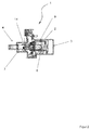
- FIGS. 1 . 2 . 5 . 6 and 7 show in each case partial views of a door, front door 1 or the like, a frame 2 made of profiles 2, in which a door 4 is rotatably mounted.
- the hinges 5 holding the door leaf 4 are here concealed on the door 1, as clearly shown in FIG FIG. 6 can be seen in the closed position of the door 1. It can be clearly seen that in the band-side longitudinal profile 2 of the frame 3, the axes of rotation 6 of the hinges 5 are fixed, wherein the door leaves 4 holding hinge plates 7 are pivotable through an open area 8 on the longitudinal profile 2 of the frame 3.
- the opening 8 is here clearly in the FIGS. 6 and 7 to see more clearly where it can be clearly seen that the curved portion 9 of the hinge plate 7 protrudes through the opening 8, so that an angled position of the door panel 10 relative to the profile 2 of the frame 3 can be done.
- the curved portion 9 of the hinge plate 7 retracts back into the cavity of the profile 2 of the frame 2, wherein the front portion 11 of the hinge plate 7 projects into the door leaf 10 and is fixed there.
- the side-longitudinal profile of the door leaf 10 is provided with protrusions 12, which in the FIGS. 6 and 7 are clearly visible.
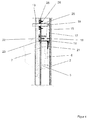
- FIG. 4 and 5 is provided in the band-side longitudinal profile 2 of the frame 3 at least one slidably mounted locking pin 13, as this in the FIG. 1 and also in the FIG. 4 can be clearly seen in the side view.
- the safety pin 13 acts in the rotational movement of the door leaf 4 in the closing or in the Opening movement, the closing movement in the FIG. 1 and the opening movement in the FIG. 4 is closer to recognize, with the hinge plate 7 in the longitudinal profile 2 of the frame 1 of the kind that in the closed state of the FIG. 1 and 6 the securing bolt 13 engages in the side facing the hinge hinge side door longitudinal profile 14, wherein in the open state of the door. 1 FIG. 4 and 7 the safety pin 13 automatically retracts into the longitudinal profile 2 of the frame 1, as shown in the FIG. 7 and 4 is shown.
- the axis of rotation 18 of the rocker 17 is fixed by means of a holder 22 in the hollow cross section of the frame profile 2, as can be seen from the FIG. 1 , but also from the FIG. 4 is recognizable.
- the bracket 22 of Rocker 17 is screwed to the fastening screws 23 of the fixed profile 2 in the hinge 5.
- a guide sleeve 25 is provided on the profile 2 at the opening 24 for the safety pin 13, which can be placed with screws 26 on the profile 2, so that the guide portion is administratfuttert for the safety pin 13, and a Sich- Tilting of the securing bolt 13 is prevented during the sliding operation.
Landscapes
- Engineering & Computer Science (AREA)
- Mechanical Engineering (AREA)
- Hinges (AREA)
- Wing Frames And Configurations (AREA)
Priority Applications (1)
| Application Number | Priority Date | Filing Date | Title |
|---|---|---|---|
| EP16173662.4A EP3255232A1 (fr) | 2016-06-09 | 2016-06-09 | Porte, porte de maison au autre |
Applications Claiming Priority (1)
| Application Number | Priority Date | Filing Date | Title |
|---|---|---|---|
| EP16173662.4A EP3255232A1 (fr) | 2016-06-09 | 2016-06-09 | Porte, porte de maison au autre |
Publications (1)
| Publication Number | Publication Date |
|---|---|
| EP3255232A1 true EP3255232A1 (fr) | 2017-12-13 |
Family
ID=56116357
Family Applications (1)
| Application Number | Title | Priority Date | Filing Date |
|---|---|---|---|
| EP16173662.4A Withdrawn EP3255232A1 (fr) | 2016-06-09 | 2016-06-09 | Porte, porte de maison au autre |
Country Status (1)
| Country | Link |
|---|---|
| EP (1) | EP3255232A1 (fr) |
Citations (4)
| Publication number | Priority date | Publication date | Assignee | Title |
|---|---|---|---|---|
| DE4137050A1 (de) * | 1991-11-11 | 1993-08-26 | Huurre Clean Room Gmbh | Verschwindscharnier |
| GB2287978A (en) * | 1994-03-25 | 1995-10-04 | J E Reynolds & Co Ltd | Security bolt |
| DE19723361A1 (de) * | 1996-06-06 | 1998-01-15 | Karl Heger | Mehrfachverriegelung |
| DE102010025691B3 (de) * | 2010-06-30 | 2011-10-27 | Simonswerk, Gesellschaft mit beschränkter Haftung | Türband, insbesondere für Hohlprofilzargen |
-
2016
- 2016-06-09 EP EP16173662.4A patent/EP3255232A1/fr not_active Withdrawn
Patent Citations (4)
| Publication number | Priority date | Publication date | Assignee | Title |
|---|---|---|---|---|
| DE4137050A1 (de) * | 1991-11-11 | 1993-08-26 | Huurre Clean Room Gmbh | Verschwindscharnier |
| GB2287978A (en) * | 1994-03-25 | 1995-10-04 | J E Reynolds & Co Ltd | Security bolt |
| DE19723361A1 (de) * | 1996-06-06 | 1998-01-15 | Karl Heger | Mehrfachverriegelung |
| DE102010025691B3 (de) * | 2010-06-30 | 2011-10-27 | Simonswerk, Gesellschaft mit beschränkter Haftung | Türband, insbesondere für Hohlprofilzargen |
Similar Documents
| Publication | Publication Date | Title |
|---|---|---|
| EP1500766A2 (fr) | Appareil de levage de volet ou porte pliante à deux battants | |
| EP2762660A2 (fr) | Gâche de logement d'un pêne | |
| EP0947654B1 (fr) | Charnière cachée | |
| EP0452710B1 (fr) | Dispositif de commande de séquence de fermeture des portes à double battants | |
| EP2871312B1 (fr) | Dispositif d'aération par entrebâillement pour porte ou fenêtre coulissante et porte ou fenêtre coulissante | |
| DE102012100424A1 (de) | Vorrichtung für das Steuern der Schliessfolge von zweiflügeligen Schwenktüren | |
| DE102004007823A1 (de) | Verdeckt angeordnetes 180-Grad-Scharnier | |
| EP3680443A1 (fr) | Portail à battant pivotant pourvu de système de protection contre le pincement | |
| DE102008028598B4 (de) | Insektenschutztür | |
| EP3255232A1 (fr) | Porte, porte de maison au autre | |
| EP2772604A2 (fr) | Limiteur d'ouverture | |
| EP2754815A2 (fr) | Ferrure de basculement pour un vantail de fenêtre ou de porte | |
| DE202016001398U1 (de) | Fenster oder Tür | |
| DE19520231C2 (de) | Torantrieb für ein Garagentor | |
| AT502083B1 (de) | Vorrichtung zur regelung der öffnungsfolge von zweiflügeligen schwenktüren | |
| DE102014111131A1 (de) | Vorrichtung zur Ver- und Entriegelung eines Fensterflügels, einer Lüftungsklappe oder dergleichen an einem Blendrahmen | |
| DE102011000072B4 (de) | Mitnehmer für einen Flügel einer zweiflügeligen Drehtür | |
| CH716231B1 (de) | Scharnier. | |
| WO2007087945A1 (fr) | Ensemble charnière permettant une liaison par l'intermédiaire d'une articulation à charnière | |
| EP3339544B1 (fr) | Armature basculante pour un vantail de fenêtre ou de porte | |
| DE1584084A1 (de) | Ausstellvorrichtung fuer Drehkippfenster | |
| DE202007010048U1 (de) | Fenster, Tür o.dgl. mit einem Schließstück | |
| EP1780362B1 (fr) | Entraînement pour vantaux pivotants | |
| EP3205803B1 (fr) | Dispositif destiné à amortir et limiter un mouvement d'ouverture | |
| CH686898A5 (de) | Gesteuerte, mehrfluegelige Durchgangstuer. |
Legal Events
| Date | Code | Title | Description |
|---|---|---|---|
| PUAI | Public reference made under article 153(3) epc to a published international application that has entered the european phase |
Free format text: ORIGINAL CODE: 0009012 |
|
| STAA | Information on the status of an ep patent application or granted ep patent |
Free format text: STATUS: THE APPLICATION HAS BEEN PUBLISHED |
|
| AK | Designated contracting states |
Kind code of ref document: A1 Designated state(s): AL AT BE BG CH CY CZ DE DK EE ES FI FR GB GR HR HU IE IS IT LI LT LU LV MC MK MT NL NO PL PT RO RS SE SI SK SM TR |
|
| AX | Request for extension of the european patent |
Extension state: BA ME |
|
| STAA | Information on the status of an ep patent application or granted ep patent |
Free format text: STATUS: REQUEST FOR EXAMINATION WAS MADE |
|
| 17P | Request for examination filed |
Effective date: 20180308 |
|
| RBV | Designated contracting states (corrected) |
Designated state(s): AL AT BE BG CH CY CZ DE DK EE ES FI FR GB GR HR HU IE IS IT LI LT LU LV MC MK MT NL NO PL PT RO RS SE SI SK SM TR |
|
| STAA | Information on the status of an ep patent application or granted ep patent |
Free format text: STATUS: EXAMINATION IS IN PROGRESS |
|
| 17Q | First examination report despatched |
Effective date: 20210528 |
|
| STAA | Information on the status of an ep patent application or granted ep patent |
Free format text: STATUS: THE APPLICATION IS DEEMED TO BE WITHDRAWN |
|
| 18D | Application deemed to be withdrawn |
Effective date: 20211008 |