EP3284898B1 - Dichtung mit einer über zwei scherenmechanismen absenkbaren dichtleiste - Google Patents
Dichtung mit einer über zwei scherenmechanismen absenkbaren dichtleiste Download PDFInfo
- Publication number
- EP3284898B1 EP3284898B1 EP16193807.1A EP16193807A EP3284898B1 EP 3284898 B1 EP3284898 B1 EP 3284898B1 EP 16193807 A EP16193807 A EP 16193807A EP 3284898 B1 EP3284898 B1 EP 3284898B1
- Authority
- EP
- European Patent Office
- Prior art keywords
- module
- housing
- seal
- scissor
- seal according
- Prior art date
- Legal status (The legal status is an assumption and is not a legal conclusion. Google has not performed a legal analysis and makes no representation as to the accuracy of the status listed.)
- Active
Links
Images





Classifications
-
- E—FIXED CONSTRUCTIONS
- E06—DOORS, WINDOWS, SHUTTERS, OR ROLLER BLINDS IN GENERAL; LADDERS
- E06B—FIXED OR MOVABLE CLOSURES FOR OPENINGS IN BUILDINGS, VEHICLES, FENCES OR LIKE ENCLOSURES IN GENERAL, e.g. DOORS, WINDOWS, BLINDS, GATES
- E06B7/00—Special arrangements or measures in connection with doors or windows
- E06B7/16—Sealing arrangements on wings or parts co-operating with the wings
- E06B7/18—Sealing arrangements on wings or parts co-operating with the wings by means of movable edgings, e.g. draught sealings additionally used for bolting, e.g. by spring force or with operating lever
- E06B7/20—Sealing arrangements on wings or parts co-operating with the wings by means of movable edgings, e.g. draught sealings additionally used for bolting, e.g. by spring force or with operating lever automatically withdrawn when the wing is opened, e.g. by means of magnetic attraction, a pin or an inclined surface, especially for sills
- E06B7/215—Sealing arrangements on wings or parts co-operating with the wings by means of movable edgings, e.g. draught sealings additionally used for bolting, e.g. by spring force or with operating lever automatically withdrawn when the wing is opened, e.g. by means of magnetic attraction, a pin or an inclined surface, especially for sills with sealing strip being moved to a retracted position by elastic means, e.g. springs
Definitions
- the present invention relates to a seal for a door, with at least two scissor mechanisms, with a sealing strip that can be lowered via the at least two scissor mechanisms, and with overload mechanisms that become effective when the sealing strip is prevented from moving completely downwards, with each scissor mechanism being assigned an overload mechanism.
- the two in the documents CH 465 830 and DE 60 2004 009 845 T2 The seals described have continuous trigger rods from their triggers to a reset mechanism.
- the scissor mechanisms are coupled to these trigger rods via the overload mechanisms, which transfer a horizontal movement of the trigger of a seal mounted in a door into a vertical movement of the sealing strip.
- the seal from the document CH 465 830 comprises springs indicated in said document by the reference numeral 16, each associated with a scissor mechanism of the disclosed seal.
- the function of the springs is described in the document in such a way that by means of the springs 16 there is a delayed transmission of the movement of a trigger of the seal into the scissor mechanisms and the sealing strip.
- these springs act, which is not mentioned in the document, to protect the seal from an overload that can arise if the path of the sealing strip specified by the setting and installation of the seal in or on a door when the seal is released from which reason is always blocked and the sealing strip can not cover the specified path.
- the springs 16 are charged when the springs are triggered and remain charged since they the force introduced by the trigger cannot be transferred to the blocked sealing strip and the scissor mechanisms blocked as a result.
- a reset mechanism but also the scissor mechanisms are supported on a housing of the seals.
- the return mechanism and also the scissor mechanisms have structures that are fixed (return mechanism) or pivoted (scissor mechanisms) to the housing.
- the inner housing is referred to in the document as the motion module section.
- This inner housing is firmly connected to an outer housing and extends over the entire length of the seal.
- the outer housing is referred to in the document as the housing section.
- the two seals have some disadvantages.
- a disadvantage is that the seal can hardly be adapted to different door widths and groove widths.
- the length of the seal is determined by the width and length of the entirety of all mechanisms in the seal, namely the scissor mechanisms, the overload mechanisms and the reset mechanism, and also the length of the trigger rod. This makes it necessary to produce different seals for door leaves of different lengths and widths. For the production, a large number of different parts in different sizes must be kept.
- the invention is based on the object of proposing a seal which is constructed in such a way that parts of the seal can be used in another seal of a different size.
- the seal has at least two modules and each module has a module housing, one of the scissor mechanisms and the overload mechanism assigned to the scissor mechanism.
- the modules provided in a seal according to the invention are predominantly arranged in a housing of the seal. In principle, however, it is conceivable that a seal according to the invention has no housing and the modules are mounted directly on a door leaf or in a groove of a door leaf.
- an interior space of the housing must be as wide or wider than the outer width of the modules.
- a housing with basically any width can be provided with a seal according to the invention. Basically, the housing can also be replaced later. A detachable fastening of the modules in the housing would then have to be provided for this purpose.
- the independence of the width of the housing from the width of the modules is achieved in particular in that the modules arranged in the mechanisms of a seal according to the invention, and these being the scissor mechanisms and the overload mechanisms, and optionally a reset mechanism and trigger, which are held, supported, guided or supported solely by the module housings so that there is no direct connection between the housing and the mechanisms.
- the housing and the mechanisms are connected to each other exclusively via the module housing.
- the sealing strip does not encompass the outside of the housing. It is then at best possible for the sealing strip to enclose the module housing on the outside. It is possible that both a retaining profile and a sealing profile or only one of the two profiles surround the outside of the module housing and engages in a gap between the housing and the module housing.
- the seal according to the invention also offers options for adapting to different door leaf widths without having to design a completely new seal.
- first module only the position of a first module is specified when this first module triggers the seal according to the invention includes.
- the position can then be specified because the trigger is guided in the module housing and the trigger protrudes laterally from the housing and the module housing of the first module when the seal is not triggered, because otherwise the trigger cannot be actuated.
- the position of the first module can be freely determined.
- a connection is advantageously created between the trigger and the first module, in particular the scissor mechanism of the first module, in order to transmit the movement of the trigger to the scissor mechanism of the first module.
- a first connecting rod can be provided, which connects the trigger and a sliding part of the first module to one another.
- the trigger can also be connected directly to the displacement part of the first module.
- the movement of the trigger can be transferred via the overload mechanism of the first module to the scissor mechanism of the first module.
- the first displacement bar can be part of the first module. This is particularly the case when the trigger is also part of the first module.
- the length of the first connecting rod if it and also the trigger are part of the first module, can be decisively predetermined by the length of the module housing in the direction of the trigger. If the trigger is not part of the first module, the length of the first connecting rod can be chosen in such a way as the specialist deems appropriate.
- the second module or the second modules of a seal according to the invention can also have a sliding part that absorbs the movement of the trigger and transmits it to the scissor mechanism via the overload mechanism.
- the sliding parts of the second module or modules can be connected to the sliding part of the first module or to one another via second connecting rods.
- the length of the connecting rod or rods can be chosen according to the desired position of the second module or modules.
- the first tie rod, first module slide, second tie rod(s) and second module slide(s) form a trigger rod which transmits movement of the trigger to all scissor mechanisms of the seal.
- This trigger rod can also transmit a restoring force provided by the reset mechanism to all of the scissor mechanisms and to the trigger to change the seal from the deployed condition to the unactuated condition when the trigger is relieved of an actuating force.
- the connecting rods can be guided in one or more module housings.
- the reset mechanism may be part of the second module or one of the second modules. If several second modules are provided, it can, for example, be part of the last second module viewed from the trigger or a module between the first and the last of the second modules.
- the resetting mechanism is part of the first module.
- the module housings it is possible for the module housings to have at least one substantially uniform external cross-sectional profile in their longitudinal extent.
- the cross-sectional profile of the module housings may be uniform along the entire length of the module housings.
- the few recesses can be, for example, holes, slots, projections or the like, which are intended to connect the parts of the module firmly to the module housing or to pivot them on the module housing.
- the housing of a seal according to the invention can have a substantially uniform internal profile in its longitudinal extension.
- the cross-sectional profile of the housing may be uniform along the entire length of the housing with some exceptions.
- the exceptions can be, for example, structures that are intended to fix the module housing in the housing.
- the module housing of a seal according to the invention can have one or more structures on its outside, which are inserted into complementary structures in the interior of the housing. In this way, easy positioning of the modules in the housing is possible.
- the complementary structure of the housing can be deformed, so that a relative movement between the module housing and the housing is prevented.
- An embodiment of the seal according to the invention has a housing 1 which has a constant cross-sectional profile over its length.
- the housing essentially has the shape of an inverted U with two legs 12 and a connecting web 11 which connects the two legs 12 to one another.
- the opposite sides 1112 of the webs 111 are slightly inclined.
- the housing can be fixed in a known manner in a groove of a door leaf.
- the attachment can be done, for example, with the help of mounting brackets, which will be discussed later.
- the person skilled in the art is familiar with various types of attachment from the prior art, in particular from published patent applications.
- the housing may be modified to provide, for example, channels, ridges, screw holes or anything else in the housing that is convenient for attaching the seal to a door.
- a seal also has a sealing strip.
- the sealing strip is in two parts. However, it could be in one piece or have more than two parts. Basically, any sealing strip known from the prior art can be used.
- the sealing strip comprises a rigid retaining profile 13, preferably made of aluminum, and an elastomeric sealing profile 14. In the example, both have a constant cross-sectional profile over their length.
- the holding profile 13, like the sealing profile, is essentially U-shaped in cross section.
- the retaining profile 13 as well as the sealing profile 14 each have a connecting web 131, 141 and two legs 132, 142 which are connected to one another via the connecting web 131, 142.
- the sealing profile 14 is fastened in locking channels 133 of the retaining profile 13 via locking webs 143 .
- two webs 134 are provided which, together with the connecting web 131, form channels whose purpose will be explained in more detail below.
- Two modules Ma, Mb are arranged in the seal, which, in the exemplary embodiment, include all parts that are used for safe movement of the sealing strip relative to the housing.
- the parts of the seal belonging to the modules Ma, Mb are partly identical in both modules. These parts can then be used in the modules Ma, Mb for the same functions of the modules Ma, Mb. Some of the modules Ma, Mb also have special functions that require special parts. In another exemplary embodiment of a seal according to the invention, functions which the first module has in the example can be performed by the second module and vice versa. It is therefore within the scope of the invention, the parts of the modules Ma, Mb to modify them so that they can also take on fewer, different or additional functions.
- Identical or functionally similar parts of the modules Ma, Mb have reference numbers with the same numbers and are distinguished by the appended letters a and b, where a stands for parts of the first module and b for parts of the second module.
- a stands for parts of the first module
- b stands for parts of the second module.
- both modules Ma, Mb of the seal according to the invention have the function of connecting the sealing strip and the housing and, when the seal is triggered by pressing a trigger 16, converting the movement of the trigger 16 into a movement of the sealing strip relative to the housing 1.
- each module Ma, Mb has a scissor mechanism Sa, Sb.
- this scissor mechanism Sa, Sb of each module Ma, Mb in what is known as an overload situation, each module Ma, Mb also has an overload mechanism Ua, Ub.
- the modules Ma, Mb can be placed in a housing 1 at the option of a person skilled in the art.
- a seal according to the invention it is also possible for a seal according to the invention to have no housing and for the modules to be placed directly in a groove of a door. It is possible to design a seal to have only one module.
- the first module Ma includes a module housing 2a. This has an essentially constant cross-sectional profile in the shape of an inverted U. It has a connecting web 21 which connects two legs 22 of the module housing 2a. Webs 221 are attached to the insides of the legs 22 . Together with the connecting web 21, these form channels whose function will be explained below.
- the connecting web 21 protrudes beyond the outer sides of the legs 22.
- These protruding ends 211 of the connecting web are designed in such a way that they form a fit with the grooves on the facing sides 1111 of the webs 111 of the housing 1. In particular, a loose fit with a small amount of play can form during the fit.
- the module housing 2a is pushed with the ends 211 into the grooves on the mutually facing sides 1111 of the webs 111 of the housing 1 and is thus fixed in the housing at least in a form-fitting manner.
- Complete fixation can be achieved, for example, by inward deformation of the webs 111 of the housing at least at certain points, i.e. towards the ends 211 or the legs 22. As a result, parts of the webs 111 can be pressed against the ends 211 or legs 22, so that at least one non-positive connection is established.
- the ends of the module housing 2a on the release side end flush with an end of the housing 1 on the release side.
- the connecting web 21 is missing in an area on the end of the module housing on the release side 21 at the release-side end of the module housing 2a space is created to insert a mounting bracket into the housing 1.
- the short scissor element 7a of the first module Ma is structurally identical to the short scissor element 7b of the second module Mb—is essentially H-shaped. It has a connecting web 72 from which two arms 73 and two legs 74 extend. At the ends of the arms 73, which are somewhat shorter than the legs 74, are the outwardly projecting pegs 71, the function of which has already been explained. The ends of the arms 73 rest against the webs 221, which supports the arms 73 in the event of a load in the direction of the webs 221. A load on the short scissor element 7a - and thus on the pin 71 and the arms 73 - can arise when the sealing strip is pressed against a floor when it is lowered or when the sealing strip is lowered.
- the long scissor element 6a of the first module Ma - it is structurally identical to a long scissor element 6b of the second module Mb - can be divided into two sections, namely a first section 61, which forms a frame, and a second section 62, which forms a rod forms.
- the two sections 61, 62 are connected to one another.
- the second section 62 of the long scissor element 6a has two blind holes that open to the outside.
- the inwardly projecting pins 75 of the short scissor element 7a are inserted into these blind holes.
- the long and short scissor elements 6a, 7a are pivotally connected to one another.
- the second section 62 of the long scissor element 6a has a conically tapering area 621, starting from the blind holes in the direction of the free end of the second section 62.
- This conical narrowing of the second section 62 facilitates the assembly of the short scissor element 7a on the long scissor element 6a.
- the inwardly projecting spigots 75 of the short scissors member at the most tapered end of the taper can be placed onto the second section 62 so that the spigots lie on either side of the second section. From this end of the taper, the pins 75 can then be pushed in the direction of the blind holes. In the process, the pins 75 are bent apart until they finally engage in the blind holes.
- the free end of the first section 61 or the opening present in this first section 61 serves to guide and mount the long scissor element 6a, which will be explained in more detail below. This free end is movable to the module housing 2a.
- two outwardly projecting pins 63 are provided, which are used to connect the long scissor element 6a to the holding profile 13.
- the pins 63 are movably guided and mounted in the channels formed by the webs 134 and the connecting web 131 of the holding profile 13 .
- the second section 62 of the long scissor element 6a has a width which is no greater than the spacing of the legs 74 of the short scissor element 7a. It is thus possible for the second section 62 to be immersed between the legs 74, for example when the seal is not triggered.
- the long scissors element 6a and the short scissors element 7a together form a first scissors mechanism Sa of the first module Ma, which is also present in the second module as a second scissors mechanism Sb formed by the long scissors element 6b and the short scissors element 7b.
- the first module Ma has a sliding part 3a.
- This sliding part has a flat, rod-like section 31 which extends over the entire length of the sliding part 3a.
- This flat, rod-like section 31 has approximately the shape of a T.
- Two projecting edges 311 of the rod-like section 31 protrude into the channels that are formed by the webs 221 and the connecting web 21 of the module housing 2a. The edges 311 and thus the entire sliding part 3a are slidably guided in the channels.
- the structure 32 at an end of the sliding part 3a on the trigger side serves as a first connecting structure which is provided for connecting the sliding part 3a of the first module Ma to a first connecting rod 8 . Furthermore, the structure 32 is part of the overload mechanism of the first module Ma.
- the structure 33 cooperates with the scissors mechanism Sa of the first module and is part of the overload mechanism of the first module Ma.
- the structure 34 is a second connection structure for connecting the slide part 3a of the first module Ma to a second connecting rod 9 .
- the first as well as the second connecting structure 32, 34 are designed in such a way that both tensile forces and compressive forces can be transmitted via the connecting structures 32, 34.
- the structure 33 has an arm 331 extending towards the trigger-side end, which extends parallel to the rod-like portion 31 of the sliding part 3a.
- This arm 331 reaches through the opening in the first section 61 of the long scissor element 6a of the scissor mechanism Sa of the first module Ma.
- a free end 612 of the first section 61 is thereby supported and guided between the arm 331 and the rod-like section 31 of the sliding part 3a.
- the free end 612 is held in a position between the arm 331 and the rod-like portion 31 of the slide member 3a by a holder 4a for an overload spring 5a and the overload spring 5a of the first module Ma.
- the overload spring 5a is a helical compression spring.
- the retainer 4a for the overload spring is rod-like.
- a first portion 41 is designed to be guided between the arm 331 and the rod-like portion 31 of the slider 3a.
- the first region 41 of the holder 4a has a channel on an underside, in which a web 3311, which is provided on the upper side of the arm 331, engages.
- a free end 411 of the first portion 41 is grooved and forms a bearing shell for the free end 612 of the first portion 61 of the long scissors member 6a.
- This first area is adjoined by a second area 42 which has a larger cross-sectional area than the first area 41.
- This second area 42 forms on the one hand a stop and on the other hand a first end of the overload spring 5a, which is plugged onto the third rod-like area 43 of the holder 4a, is supported on this second area.
- a second end of the overload spring 5a is supported on the structure 32 of the displacement part 3a.
- the overload spring 5a presses the holder and in particular the first region 41 of the holder against the structure 33 of the sliding part. Thereby, the free end 612 of the first portion of the long scissors member 6a is held between the arm 331 and the rod-like portion 31. As shown in FIG.
- the stop function of the second area 42 of the holder 4a ensures that the overload spring 5a does not press the free end 612 of the first section 61 of the long scissor element 6a against the structure 33, which could impair easy pivoting of the long scissor element.
- the length of the first area 41 of the holder 4a is chosen such that the free end 612 of the first section 61 of the long scissor element 6a is mounted with at least slight play between the structure 33 and the first area 41 of the holder 4a.
- a fourth area 44 adjoins the third area 43 of the holder 4a.
- This fourth area 44 is guided in a blind hole in the structure 32 .
- a lower boundary wall 321 of the blind hole has a slot open at the bottom. This slot tapers from bottom to top, i.e. from the outside in the direction of the blind hole. This makes it possible to press the fourth area 44 of the holder 4a from below through the slot into the blind hole.
- the slit is widened elastically. The fourth portion 44 of the holder 4a cannot be easily removed or fall out of the blind hole through the slot.
- the second module Mb also includes a module housing 2b.
- the module housing 2b of the second module Mb has the same cross-sectional profile as the module housing 2a of the first module. The main difference is its length.
- the Module housing 2b of the second module Mb is longer than the module housing 2a of the first module Ma. This extra length is needed to accommodate a reset mechanism R.
- the reset mechanism R serves to return the seal from a deployed condition to an unactuated condition when the seal deploying force from the trigger 16 is removed.
- the second module Mb has a sliding part 3b.
- This sliding part has a flat, rod-like section 31 which extends over the entire length of the sliding part 3a and whose cross section corresponds to that of the corresponding section 31 of the sliding part of the first module.
- the flat, rod-like section 31 carries three structures 32, 33b, 34b on its underside.
- the structure 32 at a trigger-side end of the slide part 3b serves as a first connection structure provided for connecting the slide part 3b of the second module Mb to the second connecting rod 9 . Furthermore, the structure 32 is part of the overload mechanism of the first module Ma. The structure is identical to the corresponding structure 32 of the sliding part 3a of the first module Ma.
- the structure 33b cooperates with the scissors mechanism Sb of the second module Mb and forms part of the overload mechanism Ub of the second module Mb. It also forms part of the return mechanism R.
- Structure 34b serves as part of the reset mechanism.
- the structure 34b could also serve as a second connection structure, which could serve to connect the sliding part 3b of the second module Mb to a further connecting rod 9, which is not provided in the exemplary embodiment, however.
- the overload mechanism Ub of the second module Mb is designed in exactly the same way as the overload mechanism Ua of the first module Ma.
- the scissors mechanism Sb of the second module Mb is also designed in the same way as the scissors mechanism Sa of the first module.
- the restoring mechanism R comprises a holder 10 for a restoring spring 11 and the restoring spring 15.
- the holder 10 has a first fork-shaped area 101, which has two pins 1011 on its outer sides. These pins 1011 are inserted into holes in the module case 2b of the second module Mb. As a result, the holder 10 cannot be displaced relative to the module housing 2b.
- This first area 101 is adjoined by a second area 102 onto which the return spring 11 is attached.
- the return spring 11 is a compression coil spring.
- a third area 103 also adjoins the second area. This third area is guided in a blind hole in the structure 33b of the displacement part 3b.
- a lower boundary wall 331 of the blind hole has a slot open at the bottom. This slot tapers from bottom to top, ie from the outside in the direction of the blind hole. This makes it possible to press the third area 103 of the holder 10 from below through the slot into the blind hole.
- the slit is widened elastically. The third portion 103 of the holder 10 can not easily from the blind hole through the be removed or fall out. This secures the position of the return spring in the seal.
- the connections between the trigger 16, the first connecting rod 8, the sliding part 3a of the first module Ma, the second connecting rod 9 and the sliding part 3b of the second module Mb are subjected to pressure both when releasing and when resetting, on the one hand by the pressure, which is exerted on the trigger 12 and on the other hand by the pressure exerted by the return spring 15.
- the free ends 612 of the long scissor elements 6a, 6b moves with. As a result, these ends 612 are displaced relative to the housing 1 and the module housings 2a, 2b and the pivots 71 of the short scissor elements 7a, 7b pivotally mounted therein.
- the scissor mechanisms Sa, Sb open and the sealing strip is thereby pushed down.
- a further movement of the unit consisting of the trigger 16, the first connecting rod 8, the sliding part 3a of the first Module Ma, the second connecting rod 9 and the displacement part 3b of the second module Mb then causes the free ends 612 of the long scissor elements 6a, 6b to press against the holders 4a, 4b for the overload springs 5a, 5b and move them in the direction of the trigger 16 will.
- the overload springs 5a, 5b are compressed.
- the path by which the free ends 612 can be displaced against the overload spring 5a, 5b is just as long as the path that the unit from the trigger 16, the first connecting rod 8, the displacement part 3a of the first module Ma, the second Connecting rod 9 and the sliding part 3b of the second module Mb can be moved.
- the scissor mechanisms Sa, Sb are then protected against damage due to an overload event.
Landscapes
- Engineering & Computer Science (AREA)
- Civil Engineering (AREA)
- Structural Engineering (AREA)
- Specific Sealing Or Ventilating Devices For Doors And Windows (AREA)
- Scissors And Nippers (AREA)
- Sealing Devices (AREA)
- Sheet Holders (AREA)
Description
- Die vorliegende Erfindung betrifft eine Dichtung für eine Tür, mit wenigstens zwei Scherenmechanismen, mit einer über die wenigstens zwei Scherenmechanismen absenkbaren Dichtleiste und mit Überlastmechanismen, die wirksam werden, wenn die Dichtleiste an einer vollständigen Abwärtsbewegung gehindert ist, wobei jedem Scherenmechanismus ein Überlastmechanismus zugeordnet ist.
- Aus den Dokumenten
CH 465 830 DE 60 2004 009 845 T2 sind Dichtungen mit zwei Scherenmechanismen bekannt. - Die beiden in den Dokumenten
CH 465 830 DE 60 2004 009 845 T2 beschriebenen Dichtungen weisen von ihren Auslösern bis zu einem Rückstellmechanismus durchgehende Auslöserstangen auf. Mit diesen Auslöserstangen sind über die Überlastmechanismen die Scherenmechanismen gekoppelt, die eine horizontale Bewegung des Auslösers einer in einer Tür montierten Dichtung in eine vertikale Bewegung der Dichtleiste übertragen. - Die Dichtung aus dem Dokument
CH 465 830 - In dem Dokument
DE 60 2004 009 845 T2 sind Überlastmechanismen zum Schutz der Dichtung in einem Fall einer Blockade der Dichtleiste im Absatz [0040] der Beschreibung explizit beschrieben. - Bei der Dichtung aus dem Dokument
CH 465 830 - Bei der Dichtung aus dem Dokument
DE 60 2004 009 845 T2 stützen sich ein Rückstellmechanismus, aber auch die Scherenmechanismen an einem Innengehäuse ab. Das Innengehäuse wird in dem Dokument als Bewegungsmodulabschnitt bezeichnet ist. Dieses Innengehäuse ist fest mit einem Außengehäuse verbunden und erstreckt sich über die gesamte Länge der Dichtung. Das Außengehäuse wird in dem Dokument als Gehäuseabschnitt bezeichnet. - Die beiden Dichtungen haben einige Nachteile.
- Ein Nachteil ist, dass die Dichtung kaum an unterschiedliche Türbreiten und Nutbreiten angepasst werden können. Durch die Breite und Länge der Gesamtheit aller Mechanismen in der Dichtung, nämlich der Scherenmechanismen, der Überlastmechanismen und des Rückstellmechanismus, und auch die Länge der Auslöserstange ist die Länge der Dichtung vorgegeben. Das macht es notwendig, dass für Türflügel unterschiedlicher Längen und Breiten unterschiedliche Dichtungen hergestellt werden müssen. Für die Herstellung müssen eine große Zahl unterschiedlicher Teile in verschiedenen Größen vorgehalten werden.
- Das führt dazu, dass kaum Gleichteile bei Dichtungen mit unterschiedlichen Größen verwendet werden können.
- Hier setzt die Erfindung an.
- Der Erfindung liegt die Aufgabe zu Grunde eine Dichtung vorzuschlagen, die so konstruiert ist, das Teile der Dichtung in einer weiteren Dichtung mit einer anderen Größe verwendet werden können.
- Diese Aufgabe wird gemäß der Erfindung dadurch gelöst, dass die Dichtung zumindest zwei Module aufweist und jedes Modul ein Modulgehäuse, einen der Scherenmechanismen und den dem Scherenmechanismus zugeordneten Überlastmechanismus aufweist.
- Die bei einer erfindungsgemäßen Dichtung vorgesehenen Module werden überwiegende in einem Gehäuse der Dichtung angeordnet werden. Grundsätzlich ist es aber denkbar, dass eine erfindungsgemäße Dichtung kein Gehäuse aufweist und die Module unmittelbar an einem Türflügel bzw. in einer Nut eines Türflügels montiert werden.
- Werden die Module in einem Gehäuse montiert, muss ein Innenraum des Gehäuses genauso breit oder breiter sein als die äußere Breite der Module. Mit Ausnahme der durch die äußere Breite der Module festgelegten unteren Grenze für die Breite eines Gehäuses, kann bei einer erfindungsgemäßen Dichtung ein Gehäuse mit im Grunde beliebiger Breite vorgesehen werden. Das Gehäuse kann im Grunde auch nachträglich ausgetauscht werden. Dazu wäre dann eine lösbare Befestigung der Module in dem Gehäuse vorzusehen.
- Die Unabhängigkeit der Breite des Gehäuses von der Breite der Module wird insbesondere dadurch erreicht, dass die in den Modulen angeordneten Mechanismen einer erfindungsgemäßen Dichtung, und dabei handelt es sich zunächst um die Scherenmechanismen und die Überlastmechanismen und optional um einen Rückstellmechanismus und einen Auslöser, ausschließlich von den Modulgehäusen gehalten, gestützt, geführt oder gelagert werden, so dass es keine unmittelbare Verbindung zwischen dem Gehäuse und den Mechanismen gibt. Das Gehäuse und die Mechanismen sind ausschließlich über die Modulgehäuse miteinander verbunden.
- Zwar ist bei der aus dem Dokument
DE 60 2004 009 845 T2 durch die Gestaltung der Dichtung mit einem Außengehäuse und einem Innengehäuse auch eine Flexibilität bei der Wahl der Breite des Gehäuses möglich. Diese ist aber einschränkt durch die Dichtleiste und insbesondere ein Halteprofil der Dichtleiste, welches das Gehäuse auf der Außenseite umgreift. - Dagegen kann es bei einer erfindungsgemäßen Dichtung vorzugsweise vorgesehen sein, dass die Dichtleiste die Außenseite des Gehäuses nicht umgreift. Es ist dann allenfalls möglich, dass die Dichtleiste die Modulgehäuse auf deren Außenseite umgreift. Dabei ist es möglich, dass sowohl ein Halteprofil als auch ein Dichtungsprofil oder nur eines der beiden Profile die Außenseiten der Modulgehäuse umgreifen und in einen Spalt zwischen dem Gehäuse und den Modulgehäusen eingreift.
- Im Hinblick auf die Länge einer Dichtung bietet die erfindungsgemäße Dichtung ebenfalls Möglichkeiten, eine Anpassung auf verschiedene Türflügelbreiten möglich zu machen, ohne dass eine vollständig neue Dichtung konstruiert werden muss. So ist es bei einer erfindungsgemäßen Dichtung grundsätzlich möglich, zumindest bei der Herstellung der Dichtung die Module in einer Längsrichtung der Dichtung frei zu positionieren.
- Unter Umständen ist nur die Position eines ersten Moduls vorgegeben, wenn dieses erste Modul den Auslöser der erfindungsgemäßen Dichtung umfasst. Dann kann die Position deshalb vorgegeben sein, weil der Auslöser in dem Modulgehäuse geführt ist und der Auslöser im nicht ausgelösten Zustand der Dichtung seitlich aus dem Gehäuse und dem Modulgehäuse des ersten Moduls herausragt, weil ansonsten eine Betätigung des Auslösers nicht möglich ist.
- Ist der Auslöser aber kein Teil des ersten Moduls und zum Beispiel in dem Gehäuse geführt, kann die Position des ersten Moduls frei bestimmt werden.
- Bei einer erfindungsgemäßen Dichtung ist vorteilhaft zwischen dem Auslöser und dem ersten Modul, insbesondere dem Scherenmechanismus des ersten Moduls eine Verbindung geschaffen, um die Bewegung des Auslösers auf den Scherenmechanimus des ersten Moduls zu übertragen. Dazu kann eine erste Verbindungsstange vorgesehen sein, die den Auslöser und ein Verschiebeteil des ersten Moduls miteinander verbindet. Der Auslöser kann aber auch unmittelbar mit dem Verschiebeteil des ersten Moduls verbunden sein.
- Mit dem Verschiebeteil des ersten Moduls kann die Bewegung des Auslösers über den Überlastmechanismus des ersten Moduls in den Scherenmechanismus des ersten Moduls übertragen werden.
- Die erste Verschiebestange kann ein Teil des ersten Moduls sein. Das ist insbesondere dann der Fall, wenn auch der Auslöser ein Teil des ersten Moduls ist.
- Die Länge der ersten Verbindungsstange kann, wenn sie und auch der Auslöser Teil des ersten Moduls sind, durch die Länge des Modulgehäuses in Richtung zum Auslöser maßgeblich vorgegeben sein. Ist der Auslöser kein Teil des ersten Moduls, kann die Länge der ersten Verbindungsstange so gewählt werden, wie der Fachmann es für sinnvoll hält.
- Auch das zweite Modul oder die zweiten Module einer erfindungsgemäßen Dichtung können ein Verschiebeteil aufweisen, dass die Bewegung des Auslösers aufnimmt und über den Überlastmechanismus in den Scherenmechanismus überträgt. Gemäß der Erfindung können dazu die Verschiebeteile des oder der zweiten Module über zweite Verbindungstangen mit dem Verschiebeteil des ersten Moduls bzw. untereinander verbunden sein. Die Länge der Verbindungstange bzw. der Verbindungsstangen können entsprechend der gewünschten Position des oder der zweiten Module gewählt werden.
- Die erste Verbindungsstange, das Verschiebeteil des ersten Moduls, die zweite Verbindungsstange bzw. die zweiten Verbindungsstangen und das Verschiebeteil des zweiten Moduls bzw. die Verschiebestangen der zweiten Module bilden eine Auslöserstange, die die Bewegung des Auslösers zu allen Scherenmechanismen der Dichtung überträgt. Diese Auslöserstange kann auch eine vom Rückstellmechanismus zur Verfügung gestellte Rückstellkraft zu allen Scherenmechanismen und zum Auslöser übertragen, um die Dichtung vom ausgelösten Zustand in den nicht ausgelösten Zustand zu versetzen, wenn der Auslöser von einer Betätigungskraft entlastet ist.
- Die Verbindungsstangen können in einem oder mehreren Modulgehäusen geführt sein.
- Der Rückstellmechanismus kann Teil des zweiten Moduls oder eines der zweiten Module sein. Sind mehrere zweite Module vorgesehen, kann er zum Beispiel ein Teil des vom Auslöser aus betrachtet letzten zweiten Moduls oder eines Moduls zwischen dem ersten und dem letzten der zweiten Module sein.
- Ferner ist es möglich, dass der Rückstellmechanismus Teil des ersten Moduls ist.
- Gemäß der Erfindung ist es möglich, dass die Modulgehäuse in ihrer Längserstreckung zumindest ein im Wesentlichen gleichförmiges äußeres Querschnittsprofil aufweisen. Das Querschnittsprofil der Modulgehäuse kann mit einigen Ausnahmen über die gesamte Länge der Modulgehäuse gleichförmig sein. Die wenigen Ausnehmungen können beispielsweise Löcher, Schlitze, Vorsprünge oder ähnliches sein, die dazu vorgesehen sind, die Teile des Moduls fest mit dem Modulgehäuse zu verbinden oder am Modulgehäuse schwenkbar zu lagern.
- Das Gehäuse einer erfindungsgemäßen Dichtung kann in seiner Längserstreckung ein im Wesentlichen gleichförmiges Innenprofil aufweisen. Das Querschnittsprofil des Gehäuses kann mit einigen Ausnahmen über die gesamte Länge des Gehäuses gleichförmig sein. Die Ausnahmen können beispielsweise Strukturen sein, die dazu vorgesehen sind, die Modulgehäuse in dem Gehäuse zu fixieren.
- Die Modulgehäuse einer erfindungsgemäßen Dichtung können an ihrer Außenseite eine oder mehrere Strukturen aufweisen, welche in komplementäre Strukturen im Inneren des Gehäuses eingeschoben sind. Auf diese Weise ist ein einfaches Positionieren der Module in dem Gehäuse möglich. Zum Fixieren der Position, d.h für eine feste Verbindung der Modulgehäuse mit dem Gehäuse, kann die komplementäre Struktur des Gehäuses verformt sein, so dass eine Relativbewegung zwischen den Modulgehäusen und dem Gehäuse verhindert ist.
- Weitere Merkmale und Vorteile einer erfindungsgemäßen Dichtung werden unter Bezugnahme auf die beiliegenden Abbildungen beschrieben. Darin zeigen:
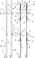
- Fig. 1 und 1a
- eine perspektivische Ansicht der erfindungsgemäßen Dichtung in einem nicht ausgelösten Zustand und in einem ausgelösten Zustand,
- Fig. 2 und 2a
- eine Frontansicht der Dichtung in einem nicht ausgelösten Zustand und in einem ausgelösten Zustand,
- Fig. 3 und 3a
- eine schlossseitige Ansicht der Dichtung in einem nicht ausgelösten Zustand und in einem ausgelösten Zustand,
- Fig. 4 und 4a
- eine bandsseitige Ansicht der Dichtung in einem nicht ausgelösten Zustand und in einem ausgelösten Zustand,
- Fig. 5 und 5a
- einen Schnitt durch die Dichtung in einem nicht ausgelösten Zustand gemäß der Linie V-V in
Fig. 2 und in einem ausgelösten Zustand gemäß der Linie Va-Va inFig. 2a , [Verbindung Halter für Rückstellfeder-Modul] - Fig. 6 und 6a
- einen Schnitt durch die Dichtung in einem nicht ausgelösten Zustand gemäß der Linie VI-VI in
Fig. 2 und in einem ausgelösten Zustand gemäß der Linie VIa-VIa inFig. 2 , [Verbindung kurzes Scherenbein-Gehäusemodul und Verbindung langes Scherenbein-Halteschiene der Dichtleiste] - Fig. 7 und 7a
- eine Frontansicht der Dichtung ohne Gehäuse und ohne Dichtleiste in einem nicht ausgelösten Zustand und in einem ausgelösten Zustand,
- Fig. 8 und 8a
- eine Frontansicht der Dichtung ohne Gehäuse, ohne Haltemodul und ohne Dichtleiste in einem nicht ausgelösten Zustand und in einem ausgelösten Zustand,
- Fig. 9 und 9a
- einen vergrößerten Ausschnitt IX aus
Fig. 8 bzw. einen vergrößerten Ausschnitt IXa ausFig. 8a , - Fig. 10 und 10a
- einen vergrößerten Ausschnitt X aus
Fig. 8 . bzw. einen vergrößerten Ausschnitt Xa ausFig. 8a , - Fig. 11
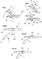
- eine perspektivische Ansicht des Scherenmechanismus,
- Fig. 12
- eine perspektivische Ansicht eines kurzen Scherenbeins,
- Fig. 13
- eine perspektivische Ansicht eines langen Scherenbeins,
- Fig. 14a und b
- Ansichten der Montage des Scherenmechanismus,
- Fig. 15a bis d
- Frontansichten von einer Einheit aus Verbindungsstangen und Verschiebeelement,
- Fig. 16a bis d
- Ansichten der vorgenannten Einheit von unten,
- Fig. 17
- eine Frontansicht eines Halters einer Überlastfeder,
- Fig. 18
- eine Ansicht des Halters der Überlastfeder von unten,
- Fig. 19a und b
- Ansichten der Montage des Überlastmechanismus,
- Fig. 20a und b
- Schnittansichten des montierten Überlastmechanismus
- Fig. 21, 21 a
- eine Variante der erfindungsgemäßen Dichtung in einem nicht ausgelösten Zustand und in einem ausgelösten Zustand,
- Eine Ausführungsform der erfindungsgemäßen Dichtung weist ein Gehäuse 1 auf, das über seine Länge ein gleichbleibendes Querschnittsprofil hat. Im dargestellten Beispiel hat das Gehäuse im Wesentlichen die Form eines umgedrehten U mit zwei Schenkeln 12 und einem Verbindungssteg 11, der die beiden Schenkel 12 miteinander verbindet. Auf einer Innenseite des Steges 11 des Gehäuses 1 sind zwei spiegelbildliche Stege 111 angebracht. Diese sind auf einander zugewandten Seiten 1111 leicht hinterschnitten, so dass die zugewandten Seiten 1111 eine Kehle bilden. Die voneinander abgewandten Seiten 1112 der Stege 111 sind leicht schräg.
- Das Gehäuse kann auf eine bekannte Art und Weise in einer Nut eines Türflügels befestigt werden. Die Befestigung kann zum Beispiel mit Hilfe von Befestigungswinkeln erfolgen, worauf noch zurückgekommen wird. Dem Fachmann sind verschiedene Arten der Befestigung aus dem Stand der Technik, insbesondere aus veröffentlichten Patentanmeldungen geläufig. Je nach Art der Befestigung kann das Gehäuse modifiziert werden, um zum Beispiel in dem Gehäuse Kanäle, Stege, Schraubenlöcher oder anderes vorzusehen, was für die Befestigung der Dichtung an einer Tür zweckdienlich ist.
- Eine Dichtung hat ferner eine Dichtleiste. Im Beispiel ist die Dichtleiste zweiteilig ausgeführt. Sie könnte aber einteilig sein oder mehr als zwei Teile aufweisen. Im Grunde kann jede aus dem Stand der Technik bekannte Dichtleiste Verwendung finden. Im Beispiel umfasst die Dichtleiste ein starres Halteprofil 13, vorzugsweise aus Aluminium, und ein elastomeres Dichtungsprofil 14. Beide haben im Beispiel über ihre Länge ein gleichbleibendes Querschnittsprofil. Im Beispiel ist das Halteprofil 13 ebenso wie das Dichtungsprofil im Querschnitt im Wesentlichen U-förmig. Das Halteprofil 13 wie auch das Dichtungsprofil 14 haben je einen Verbindungssteg 131, 141 und je zwei Schenkel 132, 142, die über den Verbindungssteg 131, 142 miteinander verbunden sind.
- Das Dichtungsprofil 14 ist über Raststege 143 in Rastkanälen 133 des Halteprofils 13 befestigt.
- Auf der Innenseite der Schenkeln 132 des Halteprofils 13 sind zwei Stege 134 vorgesehen, die zusammen mit dem Verbindungssteg 131 Kanäle ausbilden, deren Zweck noch näher erläutert wird.
- In der Dichtung sind zwei Module Ma, Mb angeordnet, die im Ausführungsbeispiel alle Teile umfassen, die einem sicheren Bewegen der Dichtleiste relativ zum Gehäuse dienen.
- Die zu den Modulen Ma, Mb zählenden Teile der Dichtung sind zum Teil identisch bei beiden Modulen zu finden. Diese Teile können dann in den Modulen Ma, Mb für gleiche Funktionen der Module Ma, Mb dienen. Zum Teil haben die Module Ma, Mb auch besondere Funktionen, die besondere Teile notwendig machen. Funktionen die im Beispiel das erste Modul hat, können bei einem anderen Ausführungsbeispiel einer erfindungsgemäßen Dichtung von dem zweiten Modul wahrgenommen werden und umgekehrt. Es liegt daher im Rahmen der Erfindung, die Teile der Module Ma, Mb so zu modifizieren, dass sie gegebenenfalls auch weniger, andere oder weitere Funktionen übernehmen können.
- Gleiche oder funktionell ähnliche Teile der Module Ma, Mb haben Bezugszeichen mit gleichen Ziffern und unterscheiden sich durch die angehängten Buchstaben a und b, wobei a für Teile des ersten Moduls und b für Teile des zweiten Moduls stehen. Sofern Details der Teile der Module Ma, Mb besprochen werden, werden diese ohne angehängte Buchstaben bezeichnet werden, wenn sie bei den Teilen beider Module Ma, Mb zu finden sind.
- Im Beispiel haben beide Module Ma, Mb der erfindungsgemäßen Dichtung die Funktion, die Dichtleiste und das Gehäuse zu verbinden und bei einer Auslösung der Dichtung durch das Eindrücken eines Auslösers 16 die Bewegung des Auslösers 16 in eine Bewegung der Dichtleiste relativ zum Gehäuse 1 umzusetzen. Dazu weist jedes Modul Ma, Mb einen Scherenmechanismus Sa, Sb auf. Um diesen Scherenmechanismus Sa, Sb jedes Moduls Ma, Mb in einem sogenannten Überlastfall zu schützen, weist jedes Modul Ma, Mb auch einen Überlastmechanismus Ua, Ub auf.
- Die Module Ma, Mb können nach Wahl eines Fachmanns in einem Gehäuse 1 platziert werden. Es ist aber auch möglich, dass eine erfindungsgemäße Dichtung kein Gehäuse aufweist und die Module unmittelbar in einer Nut einer Tür platziert werden. Es ist möglich, eine Dichtung so zu gestalten, dass sie nur ein Modul aufweist.
- Das erste Modul Ma umfasst ein Modulgehäuse 2a. Dieses hat ein im Wesentlichen gleichbleibendes Querschnittsprofil in der Form eines umgekehrten U. Es weist einen Verbindungssteg 21 auf, der zwei Schenkel 22 des Modulgehäuses 2a verbindet. Auf den Innenseiten der Schenkel 22 sind Stege 221 angebracht. Diese bilden zusammen mit dem Verbindungssteg 21 Kanäle aus, deren Funktion noch erläutert wird.
- Der Verbindungssteg 21 überragt die Außenseiten der Schenkel 22. Diese überragenden Enden 211 des Verbindungsstegs sind so gestaltet, dass sie mit den Kehlen auf den einander zugewandten Seiten 1111 der Stege 111 des Gehäuses 1 eine Passung bilden. Es kann sich bei der Passung insbesondere eine Spielpassung mit einem geringen Spiel bilden. Das Modulgehäuse 2a ist mit den Enden 211 in die Kehlen auf den einander zugewandten Seiten 1111 der Stege 111 des Gehäuses 1 eingeschoben und so in dem Gehäuse zumindest formschlüssig fixiert. Eine vollständige Fixierung kann beispielweise durch eine zumindest punktuelle Verformung der Stege 111 des Gehäuses nach innen, d.h. gegen die Enden 211 oder die Schenkel 22 erfolgen. Teile der Stege 111 können dadurch gegen die Enden 211 oder Schenkel 22 gedrückt werden, so dass zumindest eine kraftschlüssige Verbindung hergestellt ist.
- Auslöserseitige Enden des Modulgehäuses 2a enden bündig mit einem auslöserseitigen Ende des Gehäuses 1. Dagegen fehlt in einem Bereich am auslöserseitigen Ende des Modulgehäuses der Verbindungssteg 21. Das Fehlen des Verbindungssteges am auslöserseitigen Ende des Modulgehäuses 2a hat seinen Grund darin, dass durch das Fehlen des Verbindungssteges 21 am auslöserseitigen Ende des Modulgehäuses 2a Platz geschaffen ist, einen Befestigungswinkel in das Gehäuse 1 einzuschieben.
- In einem auslöserfernen Bereich des Modulgehäuses 2a des ersten Moduls Ma sind in den Schenkeln 22 unmittelbar an die Stege 221 angrenzend zwei einander gegenüberliegende Löcher vorgesehen. Entsprechende Löcher sind auch im Modulgehäuse 2b des zweiten Moduls Mb vorgesehen. In diesen Löchern sind Zapfen 71 eines kurzen Scherenelements 7a drehbar angeordnet. Diese Zapfen 71 liegen auch an der Unterseite der Stege 221 an, wodurch die Zapfen 71 bei einer Belastung in Richtung auf die Stege 221 abgestützt und vor einem Abscheren geschützt werden.
- Das kurze Scherenelement 7a des ersten Moduls Ma - es ist baugleich zum kurzen Scherenelement 7b des zweiten Moduls Mb - ist im Wesentlichen H-förmig. Es hat einen Verbindungssteg 72, von dem sich zwei Arme 73 und zwei Beine 74 erstrecken. An den Enden der Arme 73, die etwas kürzer sind als die Beine 74, sind die nach außen ragenden Zapfen 71, deren Funktion bereits erläutert wurde. Die Enden der Arme 73 liegen an den Stegen 221 an, was die Arme 73 bei einer Belastung in Richtung auf die Stege 221 abstützt. Eine Belastung des kurzen Scherenelementes 7a - und damit der Zapfen 71 und der Arme 73 - kann bei einem Anpressen der Dichtungsleiste an einen Boden beim Absenken bzw. bei abgesenkter Dichtungsleiste entstehen.
- An den Beinen 74 sind zwei nach innen ragende Zapfen 75 vorgesehen, die einer Verbindung mit einem langen Scherenelement 6a dienen.
- Das lange Scherenelement 6a des ersten Moduls Ma - es ist baugleich zu einem langen Scherenelement 6b des zweiten Moduls Mb - kann in zwei Abschnitte unterteilt werden, nämlich in einen ersten Abschnitt 61, der einen Rahmen bildet, und einen zweiten Abschnitt 62, der eine Stange bildet. Die beiden Abschnitte 61, 62 sind miteinander verbunden. Im Bereich der Verbindung weist der zweite Abschnitt 62 des langen Scherenelementes 6a zwei, nach außen geöffnete Sacklöcher auf. In diese Sacklöcher sind die nach innen ragenden Zapfen 75 des kurzen Scherenelementes 7a eingefügt. Dadurch sind das lange und das kurze Scherenelement 6a, 7a schwenkbar miteinander verbunden.
- Die in die Sachlöcher eingefügten Zapfen 75 bzw. die Enden der Beine 74 liegen an Lagerschalen 611 an, die an dem ersten Abschnitt 61 im Bereich der Verbindung des ersten Abschnitts 61 mit dem zweiten Abschnitt 62 ausgebildet sind. Dadurch ist es möglich, über die Zapfen 75 bzw. Beine 74 größere Kräfte in das lange Scherenelement 6a zu übertragen, als wenn die Lagerschalen fehlten.
- Der zweite Abschnitt 62 des langen Scherenelementes 6a hat von den Sacklöchern ausgehend in Richtung zum freien Ende des zweiten Abschnitts 62 einen sich konisch verjüngenden Bereich 621. Diese konische Verjüngung des zweiten Abschnitts 62 erleichtert die Montage des kurzen Scherenelementes 7a an dem langen Scherenelement 6a. Dazu können die nach innen ragenden Zapfen 75 des kurzen Scherenelementes am am meisten verjüngten Ende der Verjüngung auf den zweiten Abschnitt 62 gesetzt werden, so dass die Zapfen beiderseits des zweiten Abschnitts liegen. Von diesem Ende der Verjüngung können die Zapfen 75 dann in Richtung der Sacklöcher geschoben werden. Dabei werden die Zapfen 75 auseinander gebogen, bis sie schließlich in den Sacklöchern einrasten.
- Das freie Ende des ersten Abschnitts 61 bzw. die in diesem ersten Abschnitt 61 vorhandene Öffnung dient der Führung und Lagerung des langen Scherenelementes 6a, was noch näher erläutert wird. Dieses freie Ende ist beweglich zu dem Modulgehäuse 2a.
- Am freien Ende des zweiten Abschnitts 62 des langen Scherenelementes sind zwei nach außen ragenden Zapfen 63 vorgesehen, die der Verbindung des langen Scherenelementes 6a mit dem Halteprofil 13 dienen. Die Zapfen 63 sind beweglich in den durch die Stege 134 und den Verbindungssteg 131 des Halteprofils 13 gebildeten Kanälen geführt und gelagert.
- Der zweite Abschnitt 62 des langen Scherenelementes 6a hat eine Breite, die nicht größer ist als der Abstand der Beine 74 des kurzen Scherenelementes 7a. So ist es möglich, dass der zweite Abschnitt 62 zwischen die Beine 74 eingetaucht ist, zum Beispiel wenn die Dichtung nicht ausgelöst ist.
- Das lange Scherenelement 6a und das kurze Scherenelement 7a bilden zusammen einen ersten Scherenmechanismus Sa des ersten Moduls Ma, das als durch das lange Scherenelement 6b und das kurze Scherenelement 7b gebildeter zweiter Scherenmechanismus Sb beim zweiten Modul ebenso vorhanden ist.
- Das erste Modul Ma weist ein Verschiebeteil 3a auf. Dieses Verschiebeteil weist einen flachen, stangenartigen Abschnitt 31 auf, der sich über die gesamte Länge des Verschiebeteils 3a erstreckt. Dieser flache, stangenartige Abschnitt 31 hat in etwa die Form eines T. Zwei überragende Ränder 311 des stangenartigen Abschnitts 31 ragen in die Kanäle hinein, die durch die Stege 221 und den Verbindungssteg 21 des Modulgehäuses 2a gebildet sind. Die Ränder 311 und damit das ganze Verschiebeteil 3a sind verschiebbar in den Kanälen geführt.
- Auf einer Unterseite des stangenartigen Abschnitts 31 sind drei verschiedene Strukturen 32, 33a, 34a vorgesehen.
- Die Struktur 32 an einem auslöserseitigen Ende des Verschiebeteils 3a dient als erste Verbindungsstruktur, die für eine Verbindung des Verschiebeteils 3a des ersten Moduls Ma mit einer ersten Verbindungsstange 8 vorgesehen ist. Ferner ist die Struktur 32 Teil des Überlastmechanismus des ersten Moduls Ma.
- Die Struktur 33 wirkt mit dem Scherenmechanismus Sa des ersten Moduls zusammen und ist ein Teil des Überlastmechanismus des ersten Moduls Ma.
- Die Struktur 34 ist eine zweite Verbindungsstruktur, die einer Verbindung des Verschiebeteils 3a des ersten Moduls Ma mit einer zweiten Verbindungsstange 9 dient.
- Die erste wie auch die zweite Verbindungsstruktur 32, 34 sind so ausgebildet, dass sowohl Zugkräfte als aus Druckkräfte über die Verbindungsstrukturen 32, 34 übertragen werden können.
- Die Struktur 33 hat einen sich in Richtung auf das auslöserseitige Ende erstreckenden Arm 331, der sich parallel zu dem stangenartigen Abschnitt 31 des Verschiebeteils 3a erstreckt. Dieser Arm 331 durchgreift die Öffnung im ersten Abschnitt 61 des langen Scherenelementes 6a des Scherenmechanismus Sa des ersten Moduls Ma. Ein freies Ende 612 des ersten Abschnitts 61 ist dadurch zwischen dem Arm 331 und dem stangenartigen Abschnitt 31 des Verschiebeteils 3a gelagert und geführt.
- Das freie Ende 612 wird durch einen Halter 4a für eine Überlastfeder 5a und die Überlastfeder 5a des ersten Moduls Ma in einer Position zwischen dem Arm 331 und dem stangenartigen Abschnitt 31 des Verschiebeteils 3a gehalten. Bei der Überlastfeder 5a handelt es sich um eine Schraubendruckfeder. Der Halter 4a für die Überlastfeder ist stangenartig.
- Es lassen sich bei dem Halter grob vier Bereiche 41, 42, 43, 44 unterschieden.
- Ein erster Bereich 41 ist so gestaltet, dass er zwischen dem Arm 331 und dem stangenartigen Abschnitt 31 des Verschiebeteils 3a geführt ist. Dazu hat der erste Bereich 41 des Halters 4a auf einer Unterseite einen Kanal, in welchen ein Steg 3311 eingreift, welcher auf der Oberseite des Armes 331 vorgesehen ist. Ein freies Ende 411 des ersten Bereiches 41 weist eine Kehle auf und bildet eine Lagerschale für das freie Ende 612 des ersten Abschnitts 61 des langen Scherenelementes 6a.
- An diesen ersten Bereich schließt sich ein zweiter Bereich 42 an, der eine größere Querschnittsfläche hat als der erste Bereich 41. Dieser zweite Bereich 42 bildet zum Einen einen Anschlag und zum Anderen stützt sich auf diesem zweiten Bereich ein erstes Ende der Überlastfeder 5a ab, die auf den dritten stangenartigen Bereich 43 des Halters 4a gesteckt ist. Ein zweites Ende der Überlastfeder 5a stützt sich auf der Struktur 32 des Verschiebeteils 3a ab. Die Überlastfeder 5a drückt den Halter und insbesondere den ersten Bereich 41 des Halters gegen die Struktur 33 des Verschiebeteils. Dadurch wird das freie Ende 612 des ersten Abschnitts des langen Scherenelementes 6a zwischen dem Arm 331 und dem stangenartigen Abschnitt 31 gehalten. Die Anschlagsfunktion des zweite Bereichs 42 des Halters 4a sorgt dabei dafür, dass die Überlastfeder 5a das freie Ende 612 des ersten Abschnitts 61 des langen Scherenelementes 6a nicht gegen die Struktur 33 drückt, was ein leichtes Schwenken des langen Scherenelementes beeinträchtigen könnte. Die Länge des ersten Bereichs 41 des Halters 4a ist so gewählt, dass das freie Ende 612 des ersten Abschnitts 61 des langen Scherenelementes 6a zumindest mit leichtem Spiel zwischen der Struktur 33 und dem ersten Bereich 41 des Halters 4a gelagert ist.
- An den dritten Bereich 43 des Halters 4a schließt sich ein vierter Bereich 44 an. Dieser vierte Bereich 44 ist in einem Sackloch in der Struktur 32 geführt. Eine untere Begrenzungswand 321 des Sackloches weist einen nach unten offenen Schlitz auf. Dieser Schlitz ist von unten nach oben, d.h. von außen in Richtung des Sackloches, verjüngt. Dadurch ist es möglich, den vierten Bereich 44 des Halters 4a von unten durch den Schlitz in das Sackloch einzudrücken. Der Schlitz wird dabei elastisch geweitet. Der vierte Bereich 44 des Halters 4a kann nicht ohne weiteres aus dem Sackloch durch den Schlitz entnommen werden oder herausfallen.
- Auch das zweite Modul Mb umfasst ein Modulgehäuse 2b. Das Modulgehäuse 2b des zweiten Moduls Mb hat das gleiche Querschnittsprofil wie das Modulgehäuse 2a des ersten Moduls. Es unterscheidet sich im Wesentlichen durch seine Länge. Das Modulgehäuse 2b des zweiten Moduls Mb ist länger als das Modulgehäuse 2a des ersten Moduls Ma. Diese zusätzliche Länge wird für die Unterbringung eines Rückstellmechanimus R benötigt.
- Der Rückstellmechanismus R dient dazu, die Dichtung aus einem ausgelösten Zustand zurück in einen nicht ausgelösten Zustand zu bringen, wenn die die Dichtung auslösende Kraft vom Auslöser 16 genommen wird.
- Das zweite Modul Mb weist wie das erste Modul Ma ein Verschiebeteil 3b auf. Dieses Verschiebeteil weist einen flachen, stangenartigen Abschnitt 31 auf, der sich über die gesamte Länge des Verschiebeteils 3a erstreckt und dessen Querschnitt dem des entsprechenden Abschnitts 31 des Verschiebeteils des ersten Moduls entspricht.
- Der flache, stangenartige Abschnitt 31 trägt auf seiner Unterseite drei Strukturen 32, 33b, 34b.
- Die Struktur 32 an einem auslöserseitigen Ende des Verschiebeteils 3b dient als erste Verbindungsstruktur, die für eine Verbindung des Verschiebeteils 3b des zweiten Moduls Mb mit der zweiten Verbindungsstange 9 vorgesehen ist. Ferner ist die Struktur 32 Teil des Überlastmechanismus des ersten Moduls Ma. Die Struktur ist identisch zur entsprechenden Struktur 32 des Verschiebeteils 3a des ersten Moduls Ma.
- Die Struktur 33b wirkt mit dem Scherenmechanismus Sb des zweiten Moduls Mb zusammen und bildet ein Teil des Überlastmechanismus Ub des zweiten Moduls Mb. Außerdem bildet sie ein Teil des Rückstellmechanismus R.
- Die Struktur 34b dient als Teil des Rückstellmechanismus.
- Die Struktur 34b könnte auch als zweite Verbindungsstruktur dienen, die einer Verbindung des Verschiebeteils 3b des zweiten Moduls Mb mit einer weiteren Verbindungsstange 9 dienen könnte, die bei dem Ausführungsbeispiel aber nicht vorgesehen ist.
- Der Überlastmechanismus Üb des zweiten Moduls Mb ist genauso gestaltet, wie der Überlastmechanismus Üa des ersten Moduls Ma.
- Auch der Scherenmechanismus Sb des zweiten Moduls Mb ist genauso gestaltet, wie der Scherenmechanismus Sa des ersten Moduls.
- Der Rückstellmechanismus R umfasst neben den genannten Strukturen 33b und 34b einen Halter 10 für eine Rückstellfeder 11 und die Rückstellfeder 15. Der Halter 10 weist einen ersten gabelförmigen Bereich 101 auf, der an seinen Außenseiten zwei Zapfen 1011 hat. Diese Zapfen 1011 sind in Löcher in dem Modulgehäuse 2b des zweiten Moduls Mb eingesetzt. Dadurch ist der Halter 10 gegenüber dem Modulgehäuse 2b unverschiebbar.
- An diesen ersten Bereich 101 schließt sich ein zweiter Bereich 102 an, auf den die Rückstellfeder 11 aufgesteckt ist. Die Rückstellfeder 11 ist eine Schraubendruckfeder.
- An den zweiten Bereich schließt sich noch ein dritter Bereich 103 an. Dieser dritte Bereich ist in einem Sackloch der Struktur 33b des Verschiebeteils 3b geführt. Eine untere Begrenzungswand 331 des Sackloches weist einen nach unten offenen Schlitz auf. Dieser Schlitz ist von unten nach oben, d.h. von außen in Richtung des Sackloches, verjüngt. Dadurch ist es möglich, den dritten Bereich 103 des Halters 10 von unten durch den Schlitz in das Sackloch einzudrücken. Der Schlitz wird dabei elastisch geweitet. Der dritte Bereich 103 des Halters 10 kann nicht ohne weiteres aus dem Sackloch durch den Schlitz entnommen werden oder herausfallen. Dadurch ist die Lage der Rückstellfeder in der Dichtung gesichert.
- Die Verbindungen zwischen dem Auslöser 16, der ersten Verbindungsstange 8, dem Verschiebeteil 3a des ersten Moduls Ma, der zweiten Verbindungsstange 9 und dem Verschiebeteil 3b des zweiten Moduls Mb sind sowohl beim Auslösen als auch beim Rückstellen auf Druck belastet, zum Einen durch den Druck, der auf den Auslöser 12 ausgeübt wird und zum Anderen durch den Druck, der von der Rückstellfeder 15 ausgeübt wird.
- Durch die Bewegung der Einheit aus dem Auslöser 16, der ersten Verbindungsstange 8, dem Verschiebeteil 3a des ersten Moduls Ma, der zweiten Verbindungsstange 9 und dem Verschiebeteil 3b des zweiten Moduls Mb sowie der Halter 4a, 4b für die Überlastfedern werden die freien Enden 612 der langen Scherenelemente 6a, 6b mit bewegt. Dadurch werden diese Enden 612 relativ zum Gehäuse 1 und den Modulgehäusen 2a, 2b und den darin schwenkbar gelagerten Zapfen 71 der kurzen Scherenelemente 7a, 7b verschoben. Die Scherenmechanismen Sa, Sb öffnen sich und die Dichtungsleiste wird dadurch nach unten verschoben.
- Wird die Dichtungsleiste aus welchen Gründen auch immer an einer vollständigen Abwärtsbewegung gehindert, werden die oder ggf. einer der Überlastmechanismen Ua, Ub wirksam. Wird die Dichtleiste an einer (weiteren) Abwärtsbewegung gehindert, können die Scherenmechanismen Sa, Sb nicht weiter öffnen. Die freien Enden 612 der langen Scherenelemente 6a, 6b können dann nicht zusammen mit der Einheit aus dem Auslöser 16, der ersten Verbindungsstange 8, dem Verschiebeteil 3a des ersten Moduls Ma, der zweiten Verbindungsstange 9 und dem Verschiebeteil 3b des zweiten Moduls Mb verschoben werden. Eine trotz des Stillstands der Dichtleiste weiter erfolgende Bewegung der Einheit aus dem Auslöser 16, der ersten Verbindungsstange 8, dem Verschiebeteils 3a des ersten Moduls Ma, der zweiten Verbindungsstange 9 und dem Verschiebeteil 3b des zweiten Moduls Mb bewirkt dann, dass die freien Enden 612 der langen Scherenelemente 6a, 6b gegen die Halter 4a, 4b für die Überlastfedern 5a, 5b drücken und diese in Richtung zum Auslöser 16 verschoben werden. Dadurch werden die Überlastfedern 5a, 5b gestaucht.
- Vorteilhaft ist der Weg, um den die freien Enden 612 gegen die Überlastfeder 5a, 5b verschoben werden können genauso lang, wie der Weg, den die Einheit aus dem Auslöser 16, der ersten Verbindungsstange 8, dem Verschiebeteils 3a des ersten Moduls Ma, der zweiten Verbindungsstange 9 und dem Verschiebeteil 3b des zweiten Moduls Mb verschoben werden kann. Die Scherenmechanismen Sa, Sb sind dann gegen eine Beschädigung aufgrund eines Überlastfalls geschützt.
- Bei der in der
Fig. 21, 21a , dargestellten erfindungsgemäßen Variante des vorstehend beschriebenen Ausführungsbeispiels ist der Rückstellmechanismus R nicht im zweiten Modul Mb, sondern im ersten Modul Ma vorgesehen. Das hat den Vorteil, dass am auslöserfernen Ende der Dichtung der Scherenmechanismus Sb angeordnet sein könnte. Das kann für einen stärkeren Andruck der Dichtleiste an deren auslöserfernen Ende sorgen, was insbesondere für die Schlagregedichtigkeit der Dichtung von Bedeutung sein kann. - 1
- Gehäuse
- 2a
- Modulgehäuse des ersten Moduls
- 2b
- Modulgehäuse des zweiten Moduls
- 3a
- Verschiebeteil des ersten Moduls
- 3b
- Verschiebeteil des zweiten Moduls
- 4a
- Halter für die Überlastfeder des ersten Moduls
- 4b
- Halter für die Überlastfeder des zweiten Moduls
- 5a
- Überlastfeder des ersten Moduls
- 5b
- Überlastfeder des zweiten Moduls
- 6a
- langes Scherenelement des Scherenmechanismus des ersten Moduls
- 6b
- langes Scherenelement des Scherenmechanismus des zweiten Moduls
- 7a
- kurzes Scherenelement des Scherenmechanismus des ersten Moduls
- 7b
- kurzes Scherenelement des Scherenmechanismus des zweiten Moduls
- 8
- erste Verbindungsstange
- 9
- zweite Verbindungsstange
- 10
- Halter für die Rückstellfeder
- 13
- Halteprofil
- 14
- Dichtungsprofil
- 15
- Rückstellfeder
- 16
- Auslöser
- Ma
- erstes Modul
- Mb
- zweites Modul
- Sa
- Scherenmechanismus des ersten Moduls
- Sb
- Scherenmechanismus des zweiten Moduls
- Ua
- Überlastmechanismus
- Ub
- Überlastmechanismus
- R
- Rückstellmechanismus
Claims (14)
- Dichtung für eine Tür, mit wenigstens zweiScherenmechanismen (Sa, Sb), mit einer über die wenigstens zwei Scherenmechanismen (Sa, Sb) absenkbaren Dichtleiste (13, 14) und mit Überlastmechanismen (Ua, Ub), die wirksam werden, wenn die Dichtleiste an einer vollständigen Abwärtsbewegung gehindert ist, wobei jedem Scherenmechanismus (Sa, Sb) einer der Überlastmechanismen (Ua, Ub) zugeordnet ist,dadurch gekennzeichnet, dassdie Dichtung zumindest zwei Module aufweist und jedes Modul (Ma, Mb) ein Modulgehäuse (2a, 2b), einen der Scherenmechanismen (Sa, Sb) und den dem Scherenmechanismus zugeordneten Überlastmechanismus (Ua, Ub) aufweist.
- Dichtung nach Anspruch 1, dadurch gekennzeichnet, dass die Dichtung ein Gehäuse (1) aufweist und dass die Modulgehäuse (2a, 2b) in dem Gehäuse angeordnet sind.
- Dichtung nach Anspruch 1 oder 2, dadurch gekennzeichnet, dass die Module (Ma, Mb) wenigstens je ein Verschiebeteil (3a, 3b) aufweisen, das in dem Modulgehäuse (2a, 2b) des jeweiligen Moduls (Ma, Mb) verschiebbar angeordnet ist.
- Dichtung nach Anspruch 3, dadurch gekennzeichnet, dass ein erstes Modul (Ma) der Module (Ma, Mb) einen Auslöser (16) umfasst, der in einem nicht ausgelösten Zustand seitlich über das Modulgehäuse (2a) und/oder das Gehäuse (1) hinausragt und zum Auslösen der Dichtung in Richtung in das Modulgehäuse (2a) und/oder Gehäuse (1) einschiebbar ist.
- Dichtung nach Anspruch 4, dadurch gekennzeichnet, dass der Auslöser (16) unmittelbar mit dem Verschiebeteil (3a) des ersten Moduls (Ma) verbunden ist oder über eine erste Verbindungsstange (8) mit dem Verschiebeteil (3a) des ersten Moduls (2a) verbunden ist.
- Dichtung nach Anspruch 5, dadurch gekennzeichnet, dass der Auslöser (12) vom Modulgehäuse (2a) des ersten Moduls (Ma) geführt ist und die erste Verbindungsstange (8) in dem ersten Modulgehäuse (2a) des ersten Moduls (Ma) geführt ist.
- Dichtung nach einem der Ansprüche 3 bis 6, dadurch gekennzeichnet, dass jedes Verschiebeteil (3a, 3b) eines Moduls (Ma, Mb) über den Überlastmechanismus (Ua, Ub) mit dem Scherenmechanismus (Sa, Sb) zur Übertragung einer Bewegung des Auslösers (16) in die Dichtleiste (13, 14) gekoppelt ist.
- Dichtung nach einem der Ansprüche 3 bis 7, dadurch gekennzeichnet, dass die Verschiebeteile (3a, 3b) der Module (Ma, Mb) untereinander durch zweite Verbindungsstangen (9) verbunden sind.
- Dichtung nach einem der Ansprüche 4 bis 8, dadurch gekennzeichnet, dass die Dichtung einen Rückstellmechanismus (R) aufweist, um die Dichtung aus einem ausgelösten Zustand in einen nicht ausgelösten Zustand zurück zu stellen.
- Dichtung nach Anspruch 9, dadurch gekennzeichnet, dass der Rückstellmechanismus (R) Teil eines in einer Richtung vom Auslöser (12) weg letzten Moduls (Mb) der Dichtung ist.
- Dichtung nach Anspruch 9, dadurch gekennzeichnet, dass der Rückstellmechanismus (R) Teil eines Moduls (Ma) ist, das in einer Richtung vom Auslöser (12) weg vor dem letzten Modul (Mb) angeordnet ist.
- Dichtung nach einem der Ansprüche 1 bis 11, dadurch gekennzeichnet, dass die Modulgehäuse (2a, 2b) in ihrer Längserstreckung ein im Wesentlichen gleichförmiges äußeres Querschnittsprofil aufweisen.
- Dichtung nach einem der Ansprüche 2 bis 12, dadurch gekennzeichnet, dass das Gehäuse (1) in seiner Längserstreckung ein im Wesentlichen gleichförmiges Innenprofil aufweist.
- Dichtung nach Anspruch 12 und 13, dadurch gekennzeichnet, dass die Modulgehäuse (2a, 2b) an ihrer Außenseite eine oder mehrere Strukturen (211) aufweisen, welche in komplementäre Strukturen im Inneren des Gehäuses (1) eingeschoben sind.
Priority Applications (2)
| Application Number | Priority Date | Filing Date | Title |
|---|---|---|---|
| EP17178820.1A EP3284899B1 (de) | 2016-08-18 | 2017-06-29 | Dichtung mit zwei modulen umfassend einen scherenmechanismus |
| EP17184657.9A EP3290627B1 (de) | 2016-08-18 | 2017-08-03 | Dichtung mit einer begrenzung der bewegung der dichtungsleiste |
Applications Claiming Priority (1)
| Application Number | Priority Date | Filing Date | Title |
|---|---|---|---|
| EP16184708.2A EP3284897B1 (de) | 2016-08-18 | 2016-08-18 | Dichtung mit einer bewegbaren dichtleiste und einem rückstell- und/oder überhubmechanismus |
Publications (2)
| Publication Number | Publication Date |
|---|---|
| EP3284898A1 EP3284898A1 (de) | 2018-02-21 |
| EP3284898B1 true EP3284898B1 (de) | 2022-03-02 |
Family
ID=56802275
Family Applications (6)
| Application Number | Title | Priority Date | Filing Date |
|---|---|---|---|
| EP16184708.2A Active EP3284897B1 (de) | 2016-08-18 | 2016-08-18 | Dichtung mit einer bewegbaren dichtleiste und einem rückstell- und/oder überhubmechanismus |
| EP16193809.7A Active EP3284896B8 (de) | 2016-08-18 | 2016-10-13 | Scherenelement für einen scherenmechanismus für eine dichtung |
| EP20205161.1A Active EP3805509B1 (de) | 2016-08-18 | 2016-10-13 | Zweites scherenelement für einen scherenmechanismus für eine dichtung |
| EP16193807.1A Active EP3284898B1 (de) | 2016-08-18 | 2016-10-13 | Dichtung mit einer über zwei scherenmechanismen absenkbaren dichtleiste |
| EP17178820.1A Active EP3284899B1 (de) | 2016-08-18 | 2017-06-29 | Dichtung mit zwei modulen umfassend einen scherenmechanismus |
| EP17184657.9A Active EP3290627B1 (de) | 2016-08-18 | 2017-08-03 | Dichtung mit einer begrenzung der bewegung der dichtungsleiste |
Family Applications Before (3)
| Application Number | Title | Priority Date | Filing Date |
|---|---|---|---|
| EP16184708.2A Active EP3284897B1 (de) | 2016-08-18 | 2016-08-18 | Dichtung mit einer bewegbaren dichtleiste und einem rückstell- und/oder überhubmechanismus |
| EP16193809.7A Active EP3284896B8 (de) | 2016-08-18 | 2016-10-13 | Scherenelement für einen scherenmechanismus für eine dichtung |
| EP20205161.1A Active EP3805509B1 (de) | 2016-08-18 | 2016-10-13 | Zweites scherenelement für einen scherenmechanismus für eine dichtung |
Family Applications After (2)
| Application Number | Title | Priority Date | Filing Date |
|---|---|---|---|
| EP17178820.1A Active EP3284899B1 (de) | 2016-08-18 | 2017-06-29 | Dichtung mit zwei modulen umfassend einen scherenmechanismus |
| EP17184657.9A Active EP3290627B1 (de) | 2016-08-18 | 2017-08-03 | Dichtung mit einer begrenzung der bewegung der dichtungsleiste |
Country Status (3)
| Country | Link |
|---|---|
| EP (6) | EP3284897B1 (de) |
| MA (1) | MA43429A (de) |
| PL (2) | PL3284897T3 (de) |
Families Citing this family (10)
| Publication number | Priority date | Publication date | Assignee | Title |
|---|---|---|---|---|
| US11326393B2 (en) * | 2018-01-23 | 2022-05-10 | Dirtt Environmental Solutions Ltd. | Door with acoustic seals |
| EP3599335B1 (de) | 2018-07-27 | 2022-09-07 | Athmer OHG | Absenkbare dichtung, insbesondere für schiebetore |
| EP3699384B1 (de) | 2019-02-20 | 2022-08-17 | Athmer oHG | Dichtung mit einer absenkbaren dichtleiste, die mittels eines durch einen auslöser betätigbaren absenkmechanismus absenkbar ist |
| EP3754146B1 (de) * | 2019-06-19 | 2022-08-10 | Athmer oHG | Automatische dichtung mit einem dämpfer zur verzögerung der absenkung |
| IT201900018683A1 (it) | 2019-10-14 | 2021-04-14 | Unifor Spa | Porta con guarnizione magnetica |
| EP3859119A1 (de) * | 2020-01-31 | 2021-08-04 | Athmer OHG | Automatische dichtung mit einem überlastmechanismus und/oder einem rückstellmechanismus mit einer feder mit einem wellen-, dreicks-, sägezahnprofil oder ähnlichem profil |
| EP3940183B1 (de) | 2020-07-16 | 2023-04-19 | Athmer oHG | Führungsmittel für eine kraftübertragungsstange in einer automatischen dichtung und automatische dichtung mit einer solchen kraftübertragungsstange |
| EP4026978A1 (de) | 2021-01-11 | 2022-07-13 | Athmer OHG | Automatische dichtung für eine zweiflügelige tür mit einem stulp |
| DE202022102658U1 (de) | 2022-05-13 | 2022-05-30 | Athmer Ohg | Dichtung, insbesondere für Schiebetüren oder Schiebetore |
| EP4283088A1 (de) | 2022-05-25 | 2023-11-29 | Athmer OHG | Automatische dichtung, insbesondere für rauch- und brandschutztür |
Family Cites Families (9)
| Publication number | Priority date | Publication date | Assignee | Title |
|---|---|---|---|---|
| US2575459A (en) * | 1948-07-28 | 1951-11-20 | William T Moten | Weather strip structure for doors |
| CH465830A (de) | 1967-10-03 | 1968-11-30 | Arquint Joseph | Türabdichtung gegenüber einem schwellenlosen Boden |
| DE3935790C2 (de) * | 1989-10-27 | 1996-12-12 | Hahn Gmbh & Co Kg Dr | Automatische Bodendichtung für eine Tür |
| DE59200939D1 (de) * | 1991-04-17 | 1995-01-26 | Planet Mjt Ag | Dichtungsvorrichtung, insbesondere für Türflügel. |
| IT1296362B1 (it) * | 1997-11-05 | 1999-06-25 | Luigi Geron | Dispositivo paraspifferi autoregolante |
| NL1022757C2 (nl) | 2003-02-21 | 2004-08-24 | Elton Bv Ind & Handel | Afdichtinrichting voor een deur, deur voorzien van een dergelijke afdichtinrichting, alsmede bewegingsmodule voorzien van een bewegingsmechanisme voor een dergelijke afdichtinrichting. |
| US8381445B2 (en) * | 2008-06-17 | 2013-02-26 | John B. Higman and Valorie J. Higman | Automatically sealing multi panel sliding door assembly |
| AU2013204610B2 (en) * | 2012-04-27 | 2015-01-22 | Raven Products Pty Ltd | A drop door seal for providing an even drop with quick fit connections with a spindle |
| DE102015000197A1 (de) * | 2015-01-15 | 2016-07-21 | Buchele Gmbh | Sicherheitstürblatt |
-
2016
- 2016-08-18 EP EP16184708.2A patent/EP3284897B1/de active Active
- 2016-08-18 PL PL16184708.2T patent/PL3284897T3/pl unknown
- 2016-10-13 PL PL16193807.1T patent/PL3284898T3/pl unknown
- 2016-10-13 EP EP16193809.7A patent/EP3284896B8/de active Active
- 2016-10-13 EP EP20205161.1A patent/EP3805509B1/de active Active
- 2016-10-13 EP EP16193807.1A patent/EP3284898B1/de active Active
-
2017
- 2017-06-29 EP EP17178820.1A patent/EP3284899B1/de active Active
- 2017-08-03 EP EP17184657.9A patent/EP3290627B1/de active Active
- 2017-08-03 MA MA043429A patent/MA43429A/fr unknown
Also Published As
| Publication number | Publication date |
|---|---|
| EP3284896B8 (de) | 2022-05-18 |
| EP3284897B1 (de) | 2022-03-09 |
| EP3284898A1 (de) | 2018-02-21 |
| EP3805509A3 (de) | 2021-07-21 |
| EP3290627B1 (de) | 2026-01-07 |
| EP3284899B1 (de) | 2021-11-10 |
| EP3290627A1 (de) | 2018-03-07 |
| MA43429A (fr) | 2018-10-17 |
| EP3284897A1 (de) | 2018-02-21 |
| PL3284897T3 (pl) | 2022-08-01 |
| EP3805509B1 (de) | 2025-07-02 |
| EP3284896B1 (de) | 2022-02-09 |
| EP3284899A1 (de) | 2018-02-21 |
| EP3805509A2 (de) | 2021-04-14 |
| EP3284896A1 (de) | 2018-02-21 |
| PL3284898T3 (pl) | 2022-07-18 |
Similar Documents
| Publication | Publication Date | Title |
|---|---|---|
| EP3284896B1 (de) | Scherenelement für einen scherenmechanismus für eine dichtung | |
| EP3973130A1 (de) | Möbelbeschlag | |
| EP2474698A2 (de) | Dichtungsvorrichtung mit einem Dichtungsprofil und einem Mechanismus zum Verschieben des Dichtungsprofils bei Betätigung des Mechanismus | |
| EP4290038A2 (de) | Scharnier zum lösbaren und verschwenkbaren verbinden eines flügels mit einem basisteil | |
| DE102008037956B4 (de) | Betriebsmechanismus für ein bewegliches Verschlusselement | |
| EP2634350B1 (de) | Bewegliche Dichtung, insbesondere Schiebetürdichtung | |
| EP3098357B1 (de) | Betätigungsvorrichtung für ein ablaufventil eines spülkastens | |
| EP2050918B1 (de) | Absenkdichtung mit Durchgangsöffnung | |
| EP3699386B1 (de) | Automatische dichtung mit einem führungselement zum führen einer schubstange und verfahren zum positionieren des führungselementes in einem gehäuse der dichtung | |
| DE60012854T2 (de) | Panikstange | |
| EP3260646A1 (de) | Stehleiter mit einer vorrichtung zum sichern der stehleiter in einer aufgestellten stellung | |
| EP3599335B1 (de) | Absenkbare dichtung, insbesondere für schiebetore | |
| EP2439362B1 (de) | Panikdruckstange | |
| EP0306028A2 (de) | Ein- oder mehrteiliges Tor- oder Türblatt mit einem Stangenschloss | |
| EP1469159B1 (de) | Türdichtungsvorrichtung | |
| EP3655610B1 (de) | Absenkdichtung | |
| DE8201832U1 (de) | Falzschere für um eine waagerechte Achse schwenkbare Flügel von Fenstern, Türen und dergleichen | |
| EP4276267B1 (de) | Dichtung, insbesondere für schiebetüren oder schiebtore | |
| DE202004007565U1 (de) | Bodendichtung mit Federband | |
| EP4202171B1 (de) | Automatische dichtung mit einem träger, verbindungselementen und einer dichtungsleiste umfassend eine halteleiste und ein dichtungselement | |
| EP2685040B1 (de) | Vorspannbauteil und arbeitsverfahren für ein fenster oder eine fenstertür | |
| EP2910717B1 (de) | Stangenführung für eine stange eines schlosses | |
| EP2489795B1 (de) | Betätigungsplatte für Spülauslösung | |
| EP4212694B1 (de) | Dichtungsvorrichtung | |
| EP3085876A1 (de) | Absenkdichtungsvorrichtung und auslöseeinheit |
Legal Events
| Date | Code | Title | Description |
|---|---|---|---|
| PUAI | Public reference made under article 153(3) epc to a published international application that has entered the european phase |
Free format text: ORIGINAL CODE: 0009012 |
|
| STAA | Information on the status of an ep patent application or granted ep patent |
Free format text: STATUS: THE APPLICATION HAS BEEN PUBLISHED |
|
| AK | Designated contracting states |
Kind code of ref document: A1 Designated state(s): AL AT BE BG CH CY CZ DE DK EE ES FI FR GB GR HR HU IE IS IT LI LT LU LV MC MK MT NL NO PL PT RO RS SE SI SK SM TR |
|
| AX | Request for extension of the european patent |
Extension state: BA ME |
|
| STAA | Information on the status of an ep patent application or granted ep patent |
Free format text: STATUS: REQUEST FOR EXAMINATION WAS MADE |
|
| 17P | Request for examination filed |
Effective date: 20180309 |
|
| RBV | Designated contracting states (corrected) |
Designated state(s): AL AT BE BG CH CY CZ DE DK EE ES FI FR GB GR HR HU IE IS IT LI LT LU LV MC MK MT NL NO PL PT RO RS SE SI SK SM TR |
|
| STAA | Information on the status of an ep patent application or granted ep patent |
Free format text: STATUS: EXAMINATION IS IN PROGRESS |
|
| RIN1 | Information on inventor provided before grant (corrected) |
Inventor name: LUDWIG, MAICO Inventor name: KOWSKI, JULIAN |
|
| 17Q | First examination report despatched |
Effective date: 20180419 |
|
| GRAP | Despatch of communication of intention to grant a patent |
Free format text: ORIGINAL CODE: EPIDOSNIGR1 |
|
| STAA | Information on the status of an ep patent application or granted ep patent |
Free format text: STATUS: GRANT OF PATENT IS INTENDED |
|
| INTG | Intention to grant announced |
Effective date: 20210915 |
|
| RIN1 | Information on inventor provided before grant (corrected) |
Inventor name: KOWSKI, JULIAN Inventor name: LUDWIG, MAICO |
|
| GRAS | Grant fee paid |
Free format text: ORIGINAL CODE: EPIDOSNIGR3 |
|
| GRAA | (expected) grant |
Free format text: ORIGINAL CODE: 0009210 |
|
| STAA | Information on the status of an ep patent application or granted ep patent |
Free format text: STATUS: THE PATENT HAS BEEN GRANTED |
|
| AK | Designated contracting states |
Kind code of ref document: B1 Designated state(s): AL AT BE BG CH CY CZ DE DK EE ES FI FR GB GR HR HU IE IS IT LI LT LU LV MC MK MT NL NO PL PT RO RS SE SI SK SM TR |
|
| REG | Reference to a national code |
Ref country code: GB Ref legal event code: FG4D Free format text: NOT ENGLISH |
|
| REG | Reference to a national code |
Ref country code: CH Ref legal event code: EP Ref country code: AT Ref legal event code: REF Ref document number: 1472358 Country of ref document: AT Kind code of ref document: T Effective date: 20220315 |
|
| REG | Reference to a national code |
Ref country code: DE Ref legal event code: R096 Ref document number: 502016014576 Country of ref document: DE |
|
| REG | Reference to a national code |
Ref country code: IE Ref legal event code: FG4D Free format text: LANGUAGE OF EP DOCUMENT: GERMAN |
|
| REG | Reference to a national code |
Ref country code: FI Ref legal event code: FGE |
|
| REG | Reference to a national code |
Ref country code: NL Ref legal event code: FP |
|
| REG | Reference to a national code |
Ref country code: SE Ref legal event code: TRGR |
|
| REG | Reference to a national code |
Ref country code: LT Ref legal event code: MG9D |
|
| PG25 | Lapsed in a contracting state [announced via postgrant information from national office to epo] |
Ref country code: RS Free format text: LAPSE BECAUSE OF FAILURE TO SUBMIT A TRANSLATION OF THE DESCRIPTION OR TO PAY THE FEE WITHIN THE PRESCRIBED TIME-LIMIT Effective date: 20220302 Ref country code: NO Free format text: LAPSE BECAUSE OF FAILURE TO SUBMIT A TRANSLATION OF THE DESCRIPTION OR TO PAY THE FEE WITHIN THE PRESCRIBED TIME-LIMIT Effective date: 20220602 Ref country code: LT Free format text: LAPSE BECAUSE OF FAILURE TO SUBMIT A TRANSLATION OF THE DESCRIPTION OR TO PAY THE FEE WITHIN THE PRESCRIBED TIME-LIMIT Effective date: 20220302 Ref country code: HR Free format text: LAPSE BECAUSE OF FAILURE TO SUBMIT A TRANSLATION OF THE DESCRIPTION OR TO PAY THE FEE WITHIN THE PRESCRIBED TIME-LIMIT Effective date: 20220302 Ref country code: ES Free format text: LAPSE BECAUSE OF FAILURE TO SUBMIT A TRANSLATION OF THE DESCRIPTION OR TO PAY THE FEE WITHIN THE PRESCRIBED TIME-LIMIT Effective date: 20220302 Ref country code: BG Free format text: LAPSE BECAUSE OF FAILURE TO SUBMIT A TRANSLATION OF THE DESCRIPTION OR TO PAY THE FEE WITHIN THE PRESCRIBED TIME-LIMIT Effective date: 20220602 |
|
| PG25 | Lapsed in a contracting state [announced via postgrant information from national office to epo] |
Ref country code: LV Free format text: LAPSE BECAUSE OF FAILURE TO SUBMIT A TRANSLATION OF THE DESCRIPTION OR TO PAY THE FEE WITHIN THE PRESCRIBED TIME-LIMIT Effective date: 20220302 Ref country code: GR Free format text: LAPSE BECAUSE OF FAILURE TO SUBMIT A TRANSLATION OF THE DESCRIPTION OR TO PAY THE FEE WITHIN THE PRESCRIBED TIME-LIMIT Effective date: 20220603 |
|
| PG25 | Lapsed in a contracting state [announced via postgrant information from national office to epo] |
Ref country code: SM Free format text: LAPSE BECAUSE OF FAILURE TO SUBMIT A TRANSLATION OF THE DESCRIPTION OR TO PAY THE FEE WITHIN THE PRESCRIBED TIME-LIMIT Effective date: 20220302 Ref country code: SK Free format text: LAPSE BECAUSE OF FAILURE TO SUBMIT A TRANSLATION OF THE DESCRIPTION OR TO PAY THE FEE WITHIN THE PRESCRIBED TIME-LIMIT Effective date: 20220302 Ref country code: RO Free format text: LAPSE BECAUSE OF FAILURE TO SUBMIT A TRANSLATION OF THE DESCRIPTION OR TO PAY THE FEE WITHIN THE PRESCRIBED TIME-LIMIT Effective date: 20220302 Ref country code: PT Free format text: LAPSE BECAUSE OF FAILURE TO SUBMIT A TRANSLATION OF THE DESCRIPTION OR TO PAY THE FEE WITHIN THE PRESCRIBED TIME-LIMIT Effective date: 20220704 Ref country code: EE Free format text: LAPSE BECAUSE OF FAILURE TO SUBMIT A TRANSLATION OF THE DESCRIPTION OR TO PAY THE FEE WITHIN THE PRESCRIBED TIME-LIMIT Effective date: 20220302 Ref country code: CZ Free format text: LAPSE BECAUSE OF FAILURE TO SUBMIT A TRANSLATION OF THE DESCRIPTION OR TO PAY THE FEE WITHIN THE PRESCRIBED TIME-LIMIT Effective date: 20220302 |
|
| PG25 | Lapsed in a contracting state [announced via postgrant information from national office to epo] |
Ref country code: IS Free format text: LAPSE BECAUSE OF FAILURE TO SUBMIT A TRANSLATION OF THE DESCRIPTION OR TO PAY THE FEE WITHIN THE PRESCRIBED TIME-LIMIT Effective date: 20220702 Ref country code: AL Free format text: LAPSE BECAUSE OF FAILURE TO SUBMIT A TRANSLATION OF THE DESCRIPTION OR TO PAY THE FEE WITHIN THE PRESCRIBED TIME-LIMIT Effective date: 20220302 |
|
| REG | Reference to a national code |
Ref country code: DE Ref legal event code: R097 Ref document number: 502016014576 Country of ref document: DE |
|
| PLBE | No opposition filed within time limit |
Free format text: ORIGINAL CODE: 0009261 |
|
| STAA | Information on the status of an ep patent application or granted ep patent |
Free format text: STATUS: NO OPPOSITION FILED WITHIN TIME LIMIT |
|
| PG25 | Lapsed in a contracting state [announced via postgrant information from national office to epo] |
Ref country code: DK Free format text: LAPSE BECAUSE OF FAILURE TO SUBMIT A TRANSLATION OF THE DESCRIPTION OR TO PAY THE FEE WITHIN THE PRESCRIBED TIME-LIMIT Effective date: 20220302 |
|
| 26N | No opposition filed |
Effective date: 20221205 |
|
| PG25 | Lapsed in a contracting state [announced via postgrant information from national office to epo] |
Ref country code: MC Free format text: LAPSE BECAUSE OF FAILURE TO SUBMIT A TRANSLATION OF THE DESCRIPTION OR TO PAY THE FEE WITHIN THE PRESCRIBED TIME-LIMIT Effective date: 20220302 |
|
| PG25 | Lapsed in a contracting state [announced via postgrant information from national office to epo] |
Ref country code: LU Free format text: LAPSE BECAUSE OF NON-PAYMENT OF DUE FEES Effective date: 20221013 |
|
| P01 | Opt-out of the competence of the unified patent court (upc) registered |
Effective date: 20230616 |
|
| PG25 | Lapsed in a contracting state [announced via postgrant information from national office to epo] |
Ref country code: IT Free format text: LAPSE BECAUSE OF FAILURE TO SUBMIT A TRANSLATION OF THE DESCRIPTION OR TO PAY THE FEE WITHIN THE PRESCRIBED TIME-LIMIT Effective date: 20220302 |
|
| PG25 | Lapsed in a contracting state [announced via postgrant information from national office to epo] |
Ref country code: IE Free format text: LAPSE BECAUSE OF NON-PAYMENT OF DUE FEES Effective date: 20221013 |
|
| PG25 | Lapsed in a contracting state [announced via postgrant information from national office to epo] |
Ref country code: HU Free format text: LAPSE BECAUSE OF FAILURE TO SUBMIT A TRANSLATION OF THE DESCRIPTION OR TO PAY THE FEE WITHIN THE PRESCRIBED TIME-LIMIT; INVALID AB INITIO Effective date: 20161013 |
|
| PG25 | Lapsed in a contracting state [announced via postgrant information from national office to epo] |
Ref country code: CY Free format text: LAPSE BECAUSE OF FAILURE TO SUBMIT A TRANSLATION OF THE DESCRIPTION OR TO PAY THE FEE WITHIN THE PRESCRIBED TIME-LIMIT Effective date: 20220302 |
|
| PG25 | Lapsed in a contracting state [announced via postgrant information from national office to epo] |
Ref country code: SI Free format text: LAPSE BECAUSE OF FAILURE TO SUBMIT A TRANSLATION OF THE DESCRIPTION OR TO PAY THE FEE WITHIN THE PRESCRIBED TIME-LIMIT Effective date: 20220302 |
|
| PG25 | Lapsed in a contracting state [announced via postgrant information from national office to epo] |
Ref country code: SI Free format text: LAPSE BECAUSE OF FAILURE TO SUBMIT A TRANSLATION OF THE DESCRIPTION OR TO PAY THE FEE WITHIN THE PRESCRIBED TIME-LIMIT Effective date: 20220302 Ref country code: MK Free format text: LAPSE BECAUSE OF FAILURE TO SUBMIT A TRANSLATION OF THE DESCRIPTION OR TO PAY THE FEE WITHIN THE PRESCRIBED TIME-LIMIT Effective date: 20220302 |
|
| PG25 | Lapsed in a contracting state [announced via postgrant information from national office to epo] |
Ref country code: TR Free format text: LAPSE BECAUSE OF FAILURE TO SUBMIT A TRANSLATION OF THE DESCRIPTION OR TO PAY THE FEE WITHIN THE PRESCRIBED TIME-LIMIT Effective date: 20220302 |
|
| PG25 | Lapsed in a contracting state [announced via postgrant information from national office to epo] |
Ref country code: MT Free format text: LAPSE BECAUSE OF FAILURE TO SUBMIT A TRANSLATION OF THE DESCRIPTION OR TO PAY THE FEE WITHIN THE PRESCRIBED TIME-LIMIT Effective date: 20220302 |
|
| REG | Reference to a national code |
Ref country code: CH Ref legal event code: U11 Free format text: ST27 STATUS EVENT CODE: U-0-0-U10-U11 (AS PROVIDED BY THE NATIONAL OFFICE) Effective date: 20251101 |
|
| PGFP | Annual fee paid to national office [announced via postgrant information from national office to epo] |
Ref country code: NL Payment date: 20251021 Year of fee payment: 10 |
|
| PGFP | Annual fee paid to national office [announced via postgrant information from national office to epo] |
Ref country code: DE Payment date: 20251031 Year of fee payment: 10 |
|
| PGFP | Annual fee paid to national office [announced via postgrant information from national office to epo] |
Ref country code: GB Payment date: 20251024 Year of fee payment: 10 |
|
| PGFP | Annual fee paid to national office [announced via postgrant information from national office to epo] |
Ref country code: AT Payment date: 20251022 Year of fee payment: 10 |
|
| PGFP | Annual fee paid to national office [announced via postgrant information from national office to epo] |
Ref country code: FI Payment date: 20251028 Year of fee payment: 10 |
|
| PGFP | Annual fee paid to national office [announced via postgrant information from national office to epo] |
Ref country code: FR Payment date: 20251030 Year of fee payment: 10 |
|
| PGFP | Annual fee paid to national office [announced via postgrant information from national office to epo] |
Ref country code: BE Payment date: 20251021 Year of fee payment: 10 |
|
| PGFP | Annual fee paid to national office [announced via postgrant information from national office to epo] |
Ref country code: CH Payment date: 20251101 Year of fee payment: 10 Ref country code: SE Payment date: 20251021 Year of fee payment: 10 |
|
| PGFP | Annual fee paid to national office [announced via postgrant information from national office to epo] |
Ref country code: PL Payment date: 20251006 Year of fee payment: 10 |