EP3308229B1 - Tragbare sicherheitssteuerungsvorrichtung für industriemaschinen, insbesondere roboter - Google Patents
Tragbare sicherheitssteuerungsvorrichtung für industriemaschinen, insbesondere roboter Download PDFInfo
- Publication number
- EP3308229B1 EP3308229B1 EP16733700.5A EP16733700A EP3308229B1 EP 3308229 B1 EP3308229 B1 EP 3308229B1 EP 16733700 A EP16733700 A EP 16733700A EP 3308229 B1 EP3308229 B1 EP 3308229B1
- Authority
- EP
- European Patent Office
- Prior art keywords
- gripping portion
- longitudinal face
- electronic apparatus
- control
- supporting portion
- Prior art date
- Legal status (The legal status is an assumption and is not a legal conclusion. Google has not performed a legal analysis and makes no representation as to the accuracy of the status listed.)
- Active
Links
Images



Classifications
-
- G—PHYSICS
- G05—CONTROLLING; REGULATING
- G05B—CONTROL OR REGULATING SYSTEMS IN GENERAL; FUNCTIONAL ELEMENTS OF SUCH SYSTEMS; MONITORING OR TESTING ARRANGEMENTS FOR SUCH SYSTEMS OR ELEMENTS
- G05B19/00—Program-control systems
- G05B19/02—Program-control systems electric
- G05B19/18—Numerical control [NC], i.e. automatically operating machines, in particular machine tools, e.g. in a manufacturing environment, so as to execute positioning, movement or co-ordinated operations by means of program data in numerical form
- G05B19/409—Numerical control [NC], i.e. automatically operating machines, in particular machine tools, e.g. in a manufacturing environment, so as to execute positioning, movement or co-ordinated operations by means of program data in numerical form characterised by using manual data input [MDI] or by using control panel, e.g. controlling functions with the panel; characterised by control panel details or by setting parameters
-
- G—PHYSICS
- G05—CONTROLLING; REGULATING
- G05B—CONTROL OR REGULATING SYSTEMS IN GENERAL; FUNCTIONAL ELEMENTS OF SUCH SYSTEMS; MONITORING OR TESTING ARRANGEMENTS FOR SUCH SYSTEMS OR ELEMENTS
- G05B9/00—Safety arrangements
- G05B9/02—Safety arrangements electric
-
- G—PHYSICS
- G06—COMPUTING OR CALCULATING; COUNTING
- G06F—ELECTRIC DIGITAL DATA PROCESSING
- G06F1/00—Details not covered by groups G06F3/00 - G06F13/00 and G06F21/00
- G06F1/16—Constructional details or arrangements
- G06F1/1613—Constructional details or arrangements for portable computers
- G06F1/1626—Constructional details or arrangements for portable computers with a single-body enclosure integrating a flat display, e.g. Personal Digital Assistants [PDAs]
-
- G—PHYSICS
- G06—COMPUTING OR CALCULATING; COUNTING
- G06F—ELECTRIC DIGITAL DATA PROCESSING
- G06F3/00—Input arrangements for transferring data to be processed into a form capable of being handled by the computer; Output arrangements for transferring data from processing unit to output unit, e.g. interface arrangements
- G06F3/01—Input arrangements or combined input and output arrangements for interaction between user and computer
- G06F3/03—Arrangements for converting the position or the displacement of a member into a coded form
- G06F3/041—Digitisers, e.g. for touch screens or touch pads, characterised by the transducing means
- G06F3/042—Digitisers, e.g. for touch screens or touch pads, characterised by the transducing means by opto-electronic means
- G06F3/0425—Digitisers, e.g. for touch screens or touch pads, characterised by the transducing means by opto-electronic means using a single imaging device like a video camera for tracking the absolute position of a single or a plurality of objects with respect to an imaged reference surface, e.g. video camera imaging a display or a projection screen, a table or a wall surface, on which a computer generated image is displayed or projected
-
- H—ELECTRICITY
- H05—ELECTRIC TECHNIQUES NOT OTHERWISE PROVIDED FOR
- H05K—PRINTED CIRCUITS; CASINGS OR CONSTRUCTIONAL DETAILS OF ELECTRIC APPARATUS; MANUFACTURE OF ASSEMBLAGES OF ELECTRICAL COMPONENTS
- H05K7/00—Constructional details common to different types of electric apparatus
- H05K7/14—Mounting supporting structure in casing or on frame or rack
- H05K7/1401—Mounting supporting structure in casing or on frame or rack comprising clamping or extracting means
- H05K7/1411—Mounting supporting structure in casing or on frame or rack comprising clamping or extracting means for securing or extracting box-type drawers
-
- G—PHYSICS
- G05—CONTROLLING; REGULATING
- G05B—CONTROL OR REGULATING SYSTEMS IN GENERAL; FUNCTIONAL ELEMENTS OF SUCH SYSTEMS; MONITORING OR TESTING ARRANGEMENTS FOR SUCH SYSTEMS OR ELEMENTS
- G05B2219/00—Program-control systems
- G05B2219/30—Nc systems
- G05B2219/36—Nc in input of data, input key till input tape
- G05B2219/36159—Detachable or portable programming unit, display, pc, pda
-
- G—PHYSICS
- G05—CONTROLLING; REGULATING
- G05B—CONTROL OR REGULATING SYSTEMS IN GENERAL; FUNCTIONAL ELEMENTS OF SUCH SYSTEMS; MONITORING OR TESTING ARRANGEMENTS FOR SUCH SYSTEMS OR ELEMENTS
- G05B2219/00—Program-control systems
- G05B2219/30—Nc systems
- G05B2219/36—Nc in input of data, input key till input tape
- G05B2219/36168—Touchscreen
Definitions
- the present invention relates in general to industrial machines, such as robots, which have a control unit.
- the invention has been developed with particular reference to devices for manual control and/or programming of the aforesaid machines.
- Some industrial machines such as robots, are designed to operate in a manual mode and at least one automatic mode, which can be usually selected on a control unit of the machine.
- the manual operating mode is selected when the machine is to be controlled by an operator, for example for programming purposes, whereas the automatic operating mode is selected when the machine it to operate in an autonomous way, i.e., with operation governed exclusively by the corresponding control unit.
- TCP tool centre point
- a portable programming terminal is typically used, also known as "teach pendant".
- the operator uses specific pushbuttons of the teach pendant, known as “jog" pushbuttons or keys, which control movements of one or more axes of the robot.
- the TCP can be moved in a specific positive or negative direction within a reference system selected by the operator from among a plurality of possible reference systems.
- control unit of a robot can operate according to different modes or states, amongst which a programming mode.
- programming mode an operator acts in the proximity of the manipulator, as explained previously, for controlling operation thereof, storing the program steps, and programming the operating activity, by means of the teach pendant.
- the step of programming of the robot is clearly the one that entails the biggest risks for an operator, who must follow the TCP closely in order to control visually positioning thereof, continuously moving around the manipulator.
- the teach pendant is equipped with an emergency-stop switch and an enabling switch or enabling device.
- the enabling device is not kept by the operator in a predetermined switching position, the manipulator cannot perform any movement; on the other hand, the emergency-stop pushbutton is activated by the operator in particularly critical cases to stop operation of the robot completely.
- the programming terminals of the type referred to are dedicated devices, i.e., designed specifically according to the industrial machine that is to be controlled and/or programmed manually and produced in relatively limited series. These terminals are hence generally costly and take quite a long time to be developed.
- a dedicated programming terminal of the indicated type, provided with an ergonomic case and a touch screen is disclosed by US 2004/248619 A .
- control devices pre-arranged for connection to the control unit of a robot or of a similar industrial machine and configured for receiving in a removable way a portable electronic apparatus of the type indicated above.
- These control devices in general include a body having a gripping portion, which can be gripped by a user, to which an emergency-stop switch and an enabling switch are associated, and a supporting portion to which the portable electronic apparatus can be coupled in a removable way.
- a safety control device having a generally elongated box-like body, which houses the control circuit of the device and defines a seat within which a PDA apparatus can be inserted.
- the aforesaid seat has a lateral opening and is conceived for receiving slidably the PDA apparatus, in such a way that a display of the latter is accessible from the front of the box-like body.
- an interface connector in signal communication with the control circuit, which can be fitted in a corresponding interface connector of the PDA apparatus itself.
- the box-like body In this configuration, provided on the two opposite longitudinal sides of the box-like body are respective switches, which perform enabling functions, whereas provided at the top of the box-like body is a switch, which performs functions of emergency stop, these switches being in signal communication with the internal control circuit of the device.
- the body of the device can be gripped by the operator laterally with his hand so as to render possible pressing of one of the enabling switches.
- This embodiment is advantageous in so far as the device can be used in the same way by a right-handed operator and a left-handed operator.
- the general conformation of the device is, however, generally disadvantageous from the ergonomic standpoint, at least for the reason that the weight of the device weighs completely on just one hand of the operator, who must constantly keep an enabling switch depressed.
- the box-like body of the device is shaped so that it can be supported on the forearm of the operator, when he grips the gripping portion with one hand.
- the seat for the PDA apparatus itself consists of a recess defined at the front of the box-like body, in which the apparatus itself can be fitted from above. Also in this case, provided within the seat is at least one interface, which can be connected to an interface of the PDA apparatus itself.
- the gripping portion of the box-like body is basically defined at a longitudinal end of the box-like body, with an enabling switch on the back of the box-like body, so that it can be operated with a thumb, and with the emergency-stop switch positioned on the corresponding end face of the box-like body.
- This second embodiment is advantageous since the weight of the device can be distributed on the operator's forearm, without weighing completely on his hand, which must constantly keep the enabling switch depressed.
- the device referred to in the aforesaid prior document is a substantially dedicated device, i.e., specifically designed for mechanical and electronic coupling with a well-defined type of PDA apparatus, having certain physical dimensions and certain positions of the corresponding connection interfaces.
- the relative position of the safety devices is somewhat inconvenient for the operator since - in the aforesaid second embodiment - switching of the enabling switch entails a constant effort of just the thumb of the operator.
- to enable use of the device both by right-handed operators and by left-handed operators on the back of the box-like body there must be provided two enabling switches, in substantially opposite positions.
- the body of the device is moreover relatively cumbersome and heavy.
- DE 102010025781 A1 is a further safety control device, which can be coupled to a small standard electronic apparatus, such as a smartphone, a PDA apparatus, a palmtop or pocket personal computer, a netbook or a notebook, or the like.
- a small standard electronic apparatus such as a smartphone, a PDA apparatus, a palmtop or pocket personal computer, a netbook or a notebook, or the like.
- the body of the device has a lateral gripping portion, provided on a longitudinal face of which is an enabling switch and provided on the top of which is an emergency-stop switch.
- the gripping portion rises as a vertical bar from a lower supporting portion, associated to which are two arrest elements, configured for constraining laterally the portable electronic apparatus in an upright position, one of these arrest elements being position-adjustable.
- the gripping portion can be easily gripped by an operator like a handle, thereby enabling switching of the enabling switch.
- the solution known from DE 102010025781 A1 presents the advantage that to the safety control device there can be combined electronic apparatuses of different dimensions, by virtue of the presence of a position-adjustable arrest device, and moreover that the device can be used indifferently by right-handed and left-handed operators.
- the general conformation of the device is, however, disadvantageous from the ergonomic standpoint, both for the relative arrangement between the gripping portion and the upright position of lie of the electronic apparatus and for the fact that the weight of the device weighs completely on the hand of the operator who must constantly keep the enabling switch depressed.
- the enabling switch must generally be a pushbutton switch having three positions, and precisely a position of release, an intermediate switching position, and a final switching position.
- the position of release prevents the operator from imparting movement commands on the robot
- the intermediate switching position is the one that must be kept by the operator in the course of programming of the robot in order to enable movements thereof.
- the final switching position i.e., the position where the switch is pressed right down, corresponds to a so-called panic state and is aimed at producing basically the same effects as the position of release.
- the conformation of the gripping portion according to DE 102010025781 A1 and the corresponding position of the enabling switch renders it problematical for the operator to carry the device without causing any accidental switching of the enabling switch into the aforesaid final position.
- the present invention is basically aimed at providing a portable safety control device having a structure that is particularly advantageous from the ergonomic standpoint in order to facilitate and render less tiring the activity of use of the device itself.
- Another aim of the invention is to provide a safety control device having a structure that is simple, inexpensive, and light, as well as particularly flexible in relation to the types of electronic apparatuses that can be combined to the device itself.
- references to "an embodiment” or “one embodiment” in the framework of the present description is meant to indicate that a particular configuration, structure, or characteristic described in relation to the embodiment is comprised in at least one embodiment.
- phrases such as “in an embodiment”, “in one embodiment”, and the like that may be present in various points of the present description do not necessarily all refer to one and the same embodiment.
- the particular configurations, structures, or characteristics may be combined in any adequate way in one or more embodiments.
- the references used in what follows are only provided for convenience and do not define the sphere of protection or the scope of the embodiments. It is moreover to be pointed out that in the sequel of the present description only the elements useful for an understanding of the invention will be described.
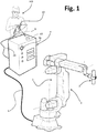
- Figure 1 is a schematic representation of an industrial machine comprising a portable safety control device according to the invention.
- the industrial machine is an anthropomorphic robot 1, having a structure 2 that is movable according to a number of degrees of freedom.
- a tool or end effector designated by 3, represented for example by a welding torch.
- the invention can in any case be used in combination with other types of industrial machines, such as for example cartesian and SCARAs robots, automated systems, work cells, etc.
- the movement of each of the movable parts of the structure 2 is controlled by a respective electric motor with corresponding reducing gear transmission.
- the movements of the structure 2 and the operations of the end effector 3 are managed by a control unit, designated by 4 in Figure 1 , which is located in a remote position with respect to the structure 2 and is connected to the latter via a cable 5.
- the control unit 4 is able to operate according to at least three different modes or states, such as for example a programming mode, an automatic mode, and a remote mode.
- these operating modes can be selected on the control unit 4, via corresponding selection means, designated as a whole by 4a.
- an operator HO acts in the proximity of the robot 1, for controlling operation thereof, storing the program steps, and programming the operating activities, by means of a portable electronic apparatus associated to a safety control device according to the invention, designated as a whole by 10.
- the device 10 has a respective control circuit, which can be connected in signal communication with the control unit 4 of the robot 1.
- the robot 1 carries out an operating program thereof, obtained as explained above, possibly in combination with other robots or automatic apparatuses, normally within a cell protected from access of staff, but under the visual control of the operator HO.
- the robot 1 carries out an operating program of its own within a cell normally protected from access of staff, but in this case start of execution of the program comes from a cell supervisor, such as a PLC, which for example controls both the robot and other automatic apparatuses present in the cell itself.
- a cell supervisor such as a PLC
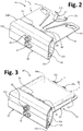
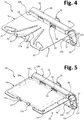
- a portable safety control device 10 according to possible embodiments of the invention is illustrated schematically in Figures 2-7 .
- the device 10 has a body 11 defining a gripping portion 12 and a supporting portion 13.
- the gripping portion 12 and the supporting portion 13 can be made of a single piece, or else made of different pieces assembled together, even made of different materials.
- the gripping portion 12 is made entirely or prevalently of a metal material, preferably aluminium, or another light metal, or a light alloy, whereas the supporting portion is made of plastic material. The use of the preferred materials indicated enables containment of the weight of the device.
- the gripping portion 12 is designed to be gripped by the hand of an operator.
- the gripping portion 12 is hollow and extends longitudinally, i.e., is generally tubular, in order to house within it a control circuit of the device 10.
- the longitudinal dimension of the supporting portion 13 is the same or substantially the same as that of the gripping portion 12.
- the portion 12 has two generally opposite longitudinal walls or faces, designated by 12a and 12b, as well as a lower longitudinal wall or face 12c and an upper longitudinal wall or face 12d, which each extend between the faces 12a and 12b.
- These faces 12a-12c will be also defined hereinafter for simplicity as “outer face”, “inner face”, “lower face”, and “upper face”, respectively.
- the gripping portion 12 is shaped in such a way that the thumb and at least one first portion of the palm of the operator's hand rests on the inner face 12b, whereas at least one end portion of the index finger, middle finger, ring finger, and little finger rest on the outer face 12b, and with an intermediate part of his hand that instead is in a position corresponding to the lower face 12c. In this way, gripping of the portion 12 is particularly natural.
- the faces 12a-12c are preferably sized and arranged so as to bestow on the gripping portion 12 a generally tapered conformation, in particular from top downwards, as is clearly visible, for example, in Figure 7 .
- the supporting portion 13 extends laterally starting from the gripping portion 12, for supporting a portable electronic apparatus thereon, designated as a whole by 50, which here is assumed as being a tablet of a type available on the market, for example an iPad® tablet produced by Apple Inc.
- the device 10 has for this purpose an interface arrangement, for connecting in signal communication the corresponding control circuit to the electronic apparatus 50.
- the device 10 according to the invention can be used in combination with standard or commercially available portable electronic apparatuses of various types, such as smartphones, tablets, PDAs, palmtops, or pocket computers. Very preferably, these devices are devices equipped with a touch screen.
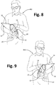
- the body 11 is shaped as a whole in such a way that the back of the supporting portion 13 is designed to rest on the forearm of an operator, when the gripping portion 12 is gripped by the corresponding hand of the operator (see Figures 8-9 ).
- the aforesaid two control members 14 and 15 are represented by an enabling switch and an emergency-stop switch, respectively, both of which are obtained, for example, via electric switches of a conception in itself known in the field, in particular pushbutton switches.
- the enabling switch 14 is a pushbutton switch having three positions, and precisely a position of release, an intermediate switching position and a final switching position where it is pressed right down (panic state), as indicated in the introductory part of the present description.
- control members 14 and 15 are both positioned on the outer face 12a of the gripping portion 12, with at least one of the control members that is positioned so as to be within the reach of more than one finger of the hand that grips the above portion 12.
- the supporting portion 13 has a substantially two-dimensional configuration, i.e., is substantially plate-shaped and extends laterally from the inner face 12b in such a way that the front of the portion 13 defines a resting surface for the back of the casing body of the electronic apparatus 50, the touch screen or display 50a of which is hence accessible from above.
- the plate-shaped supporting portion 13 has associated thereto at least one element of constraint, designated as a whole by 17, pre-arranged for locally securing the electronic apparatus 50, i.e., the casing body thereof, on the portion 13 itself.
- control members 14 and 15 are both positioned on the outer face 12a of the portion 12 is advantageous from the ergonomic standpoint.
- Each of the members 14 and 15 is normally designed to be operated by a respective hand of the operator HOP (the member 14, with the hand that grips the portion 13 and the member 15 with the other hand).
- HOP the operator
- the portion 12 is safely gripped by the other hand, with the corresponding thumb and part of the palm that effectively counter the action of thrust exerted on the member 15: this contributes to guaranteeing an immediate and safe switching of the member 15.
- control members and in particular at least the member 14, is within the reach of the index finger, middle finger, ring finger, and little finger of the hand that grips the gripping portion 12, enables the hand itself to operate in a simple way on the member itself in order to cause the desired condition of switching thereof.
- control member 15 for example on the upper face 12d of the gripping portion 12.
- the supporting portion 13 is substantially plate-shaped and is provided with one or more local constraint elements enables definition of an extensive resting surface for the electronic apparatus, without it being necessary to provide a box-like body in which to define a housing seat for the apparatus. Thanks to the above characteristics, the portion 13 has a very contained weight, to the advantage of reduction of the overall weight of the device 10. Moreover, the portion 13 offers a sufficiently extensive surface for supporting various types of electronic apparatuses, which have dimensions of lateral encumbrance that are very different from one another (and hence, for example, a plurality of tablets or smartphones which have touch screens with different dimensions or aspect ratios).
- the element or elements of constraint may be of various nature and complexity, as well as being configured for securing in position apparatuses of different dimensions, in a removable way.
- elements of constraint are provided made of elastic or resilient material, for example in the form of bands designed to withhold the electronic apparatus 50 on the portion 13 elastically and designed for co-operating with electronic apparatuses of different dimensions, by virtue of their elasticity.
- bands or straps with corresponding engagement portions for example of a Velcro type, in order to enable their useful length to be adapted according to the dimensions of the apparatuses 50 to be coupled to the portion 13.
- the aforesaid bands or straps may extend in the longitudinal and/or transverse direction of the body 11 of the device 10.
- a member of this type is designated as a whole by 17 in the figures.
- the member 17 has a body defining two arms 17a, here generally divergent from one another starting from a common base, the distal ends of which are generally bent or curved so as to be able to co-operate with the apparatus, in particular with an edge thereof that is in a position generally opposite to the gripping portion 12.
- the body of the member 17 is made of a plastic and/or elastically flexible material.
- the member 17 is mounted so as to slide on the portion 13 in a direction generally transverse to the longitudinal extension of the gripping portion 12.
- a transverse slot 18 is defined, slidably engaging in which is a threaded stem 17b ( Figure 6 ) that projects at the bottom from the body of the member 17.
- the body of the member 17 rests on the front of the portion 13, with an end portion of the stem 17b that projects at the bottom from the slot 18, on the aforesaid projecting portion there being engaged a clamping wheel 17c ( Figure 6 ).
- the position of stop of the member 17 along the slot 18 can be varied according to a dimension of lateral encumbrance of the electronic apparatus 50 to be coupled to the device 10.
- the supporting portion 13 extends from an intermediate position of the inner face 12b, with reference to the height of the latter, where this position in height is in any case closer to the upper face 12d than to the lower face 12c.
- a step can be defined, i.e., a contrast wall for the edge of the body of the body of the electronic apparatus 50 that is closer to the gripping portion 12.
- This contrast wall is designated by 12b 1 for example in Figures 4 and 5 .
- the gripping portion 12 has associated thereto one or more means of constraint for the electronic apparatus 50.
- This characteristic is preferable when the means of constraint associated to the supporting portion 13 are operative in a position generally opposite to the gripping portion 12, such as for example in the case of the member 17 described previously.
- the means of constraint associated to the gripping portion can be conveniently located in a position corresponding to the contrast wall 12b 1 .
- a case of this sort is, for example, exemplified in the figures, where designated by 19 are two constraint members associated to the wall 12b 1 , preferably made of resilient material in order to provide functions of antiscratch contrast elements for the edge of the electronic apparatus 50.
- One or more elements of constraint 19, which have even a conformation different from the one exemplified, can be overmoulded to the gripping portion 12, in particular if this is made of plastic material.
- At least one of the members 14 and 15, preferably both, is in an intermediate position of the gripping portion 12, with reference to the longitudinal dimension of the latter.
- This positioning is particularly advantageous, in so far as it enables the device 10 to be provided with a single control member 14 to performs enabling functions, instead of a pair of them, as for example in US 2005/141681 A1 .
- the device 10 can preferably be used both by right-handed operators and by left-handed operators, as is clearly exemplified in Figures 8 and 9 : from these figures, the similar modes of switching of the control member 14 in the two conditions emerge clearly.
- the presence of a single member 14 simplifies production of the device to the advantage of the reduction of its cost and weight.
- a loop-shaped strap 20 which can be engaged by the hand gripping the portion 12.
- a rubber part is provided, designated by R in Figure 6 , aimed at facilitating gripping.
- the rubber part R can extend over part of the inner face 12b and/or of the lower face 12c, preferably in a position aligned in a direction transverse to the control member 14.
- control members 14 and 15 are positioned so as to be both within the reach of more than one finger of the hand that grips the gripping portion 12.
- the members 14 and 15 are normally designed to be activated with different hands, but the characteristic in question may enable, if need be, the operator to act simultaneously on the two members 14 and 15 with the fingers of just the hand that grips the portion 12.
- the two control members 14 and 15 are in positions generally aligned to each other in a transverse direction of the outer face 12a of the gripping portion 12.
- various standard electronic apparatuses 50 which can be used for purposes of implementation of the invention - such as for example smartphones and tablets - envisage at their back the optics of a photographic camera or video-camera.
- the use of such an image-shooting device by the operator who is holding the device 20 may prove useful during programming or supervision of operation of the robot 1, for example, when capture of the image of a given operating condition of the machine becomes necessary.
- the supporting portion 13 preferably has, in its generally peripheral position, at least one through opening or at least one recess on its edge: the reason for this is to enable positioning of the electronic apparatus 50 on the portion 13 with a corresponding rear image-shooting element in a position corresponding to the aforesaid through opening or recess.
- This characteristic is visible, for example, in Figure 6 , where designated by 21 are two of the aforesaid openings, located at one of which is a rear shooting device 50b of the electronic apparatus 50.
- the number and/or shape and/or position of the openings 21 may be different from the one exemplified in order to cover a wide range of cases of devices 50 provided with a rear image-shooting member 50b.
- the device 10 comprises detection means, configured for detecting the presence of the electronic apparatus 50 associated to the device 10. These detection means are connected in signal communication with the internal control circuit of the device 10 and comprise at least one of a position-sensor device and the aforesaid interface arrangement used for connecting in data communication the electronic apparatus 50 to the control circuit of the device 10, where this interface preferably comprises a wireless transceiver module.
- the device 10 includes both of the detection means exemplified.
- the figures exemplify the case of a sensor 22 positioned on the inner wall 12b of the gripping portion 12, in particular above the resting surface 13a defined by the supporting portion 13, i.e., in a position corresponding to the contrast wall 12b 1 .
- the sensor 22 is a microswitch or similar electromechanical device, having a corresponding actuation element, which, in the absence of the device 50, projects from the gripping portion 12 in the direction of the supporting portion 13.
- the electronic apparatus 50 when the electronic apparatus 50 is positioned on the portion 13 with an edge thereof adjacent to the wall 12b 1 , a displacement of the aforesaid actuation element is brought about, with consequent switching of the microswitch 22, which signals to the control circuit the physical presence of the electronic apparatus 50 on the device 10.
- the sensor 22 may be a sensor of a type different from the one exemplified, such as a proximity sensor or an optical sensor. As will emerge clearly hereinafter, the presence of a sensor of physical position is preferable when the electronic apparatus 50 is interfaced with the control circuit of the device 10 in wireless mode.
- the gripping portion 12 is hollow, and preferably housed therein is the control circuit of the device 10 and, preferably, also the corresponding interface arrangement with the electronic apparatus 50, when this arrangement is of a wireless type.
- the portion 12 is at least one battery used for supply of the control circuit of the device 10.
- a backup or buffer battery is also provided for recharging a battery of the electronic apparatus 50.
- the gripping portion 12 has two longitudinal end walls, designated by 12e and 12f in the figures, generally opposite to one another.
- positioned on at least one of these end faces 123 and 12f is at least one of a connection port, connected in signal communication with the internal control circuit of the device 10, and a gland or bushing element.
- the end walls 12e and 12f are in a position at least slightly recessed with respect to the longitudinal end of the faces 12a-12d in such a way that the aforesaid bushing element and/or the aforesaid at least one connection port are/is in a protected position.
- a bushing element is designated by 23 for example in Figures 1-2 and 5-7 and is advantageously used for passage of a cable (designated by 24 in Figure 1 ) necessary for connection of the internal circuit of the device 10 to the control unit 4 of the robot 1. It should be noted, however, that the presence of the bushing element 23 and of the cable 24 is optional, in so far as in various embodiments the connection between the device 10 and the control unit 4 is obtained in wireless mode.
- connection ports one of which is visible only partially. These ports may be of any type and standard known in the sector, for example USB ports and/or RS-232 ports, etc. Obviously, a number of ports of different types may be provided, on one or both of the walls 12e and 12f.
- a connection port 25 or 26, for example of a USB type, can be used for interfacing with a cable the internal circuit of the device 10 to the electronic apparatus 50, via a corresponding connection port of the latter. In this way, an intrinsically safe physical or wired interfacing between the control device 10 and the electronic apparatus 50 is obtained.
- connection port 25 or 26 for example of a USB type, may be provided for connecting by means of a cable a buffer battery internal to the portion 12 with the electronic apparatus 50, for supply of the latter and/or recharging of the corresponding battery.
- a connection port of the device 10 for example a port of a USB type, can be used for removable connection of a so-called safety token, designated by ST, i.e., a physical device designed to carry out an authentication between the internal circuit of the device 10 and the control unit 4 of the robot 1.
- ST safety token
- the internal circuit of the device 10 comprises a wireless communication module, for establishing a communication line with a corresponding wireless module of the control unit 4, where this line is designed for transmission of the information on the status of the safety control members 14 and 15.
- Figure 10 is a schematic illustration, merely by way of example, of possible modes of connection between a control device 10, a control unit 4, and an electronic apparatus 50.
- the unit 4 has a processing assembly, represented schematically by the block 41, which controls general operation of the robot 1, including the logic for management of the safety functions, represented by the block 42.
- a processing assembly 41 Connected to the processing assembly 41 are a first communication interface and a second communication interface, designated by 43 and 44.
- the interface 43 is preferably represented by a wireless communication module, for example operating according to the Wi-Fi standard, whereas the interface 44 can be alternatively represented by a wired connection interface or else a further wireless communication module, preferably operating according to a standard different from that of the module 43, for example the Bluetooth standard.
- Designated as a whole by 50 is the portable electronic apparatus associated to the device 10, which includes a control unit 51 of its own connected to which are a first communication interface and a second communication interface, designated by 52 and 53, respectively.
- the interface 52 is represented by a communication module operating according to the same operating standard as that of the module 43 of the control unit 4.
- the interface 53 can be alternatively represented by a wired connection interface or else by a further wireless communication module, preferably operating according to a standard different from that of the module 52, for example the Bluetooth standard.
- Designated as a whole by 100 is the internal control circuit of the device 10, connected to which are the safety control members 14 (enabling switch) and 15 (emergency stop), the position sensor 22, the ports 25-26, as well as two corresponding communication interfaces 101 and 102.
- the interface 101 is of a type similar to the communication interface 53 of the electronic apparatus 50, and can hence be alternatively represented by a wired connection interface or else by a wireless communication module, operating according to the same standard as that of the module 53.
- the interface 102 is, instead, of a type similar to the interface 44 of the control unit 4, and can hence be alternatively represented by a wired connection interface or else by a wireless communication module, operating according to the same standard as that of the module 44.
- the information corresponding to the status of the safety control members 14 and 15 is transmitted by the circuit 100 to the processing assembly 41, via the interfaces 102 and 44, and according to the status information received by the computer assembly 41, the device 10 manages the safety logic 42 of the unit 4.
- the communication line designated by A which connects together the interfaces 102 and 44, may be, as has been said, represented by a cable or else by a wireless communication channel, preferably but not necessarily a bidirectional one.
- the modules 102 and 44 are pre-arranged for having a useful range of some metres in order to fall within the range of action of the device 10 with respect to the unit 4.
- the operator can, via the touch screen 50a of the electronic apparatus 50, impart commands of various nature to the control unit 4, according to techniques in themselves known: for this purpose, of course, stored in the memory means of the electronic apparatus 50 is the software required for this purpose.
- This software is preferably pre-arranged for emulating at least part of the functions proper to a traditional teach pendant, obviously except for the safety functions, here managed via the device 10.
- the control unit 4 can communicate data of various nature to the device 50, once again according to techniques in themselves known. For example, via the display 50a of the electronic apparatus 50 it is possible to monitor the machine states, the program steps, possible alarms, and various parameters, such as the position of the axes of the robot.
- the functions of the means 4a of the control unit 4, of selection of the operating modes of the robot (programming mode, automatic mode, remote mode).
- the interfaces 53 and 101 are represented by wireless communication modules it is preferable for these to be pre-arranged for having a limited useful range, indicatively not greater than one metre.
- the device 10 in addition to such a short-range communication it is in any case advantageous for the device 10 to be equipped with a sensor, such as the microswitch previously designated by 22, for detecting the physical presence of the electronic apparatus 50 on the control device 10 and hence preventing an operator from imparting commands on the robot via an electronic apparatus 50 set in the proximity of the control device 10, but not mounted thereon.
- a unique pairing is necessary between the corresponding control systems, i.e., a condition of safe communication between them.
- a unique pairing i.e., a safe communication, is likewise necessary between the device 10 and the control unit 40, when the information on the status of the control members 14 and 15 occurs in wireless mode.
- pairing between the electronic apparatus 50 and the device 10 must be unique, when it is not obtained via a cable.
- the practical modalities of identification and safe communication between the unit 4, the device 10, and the electronic apparatus 50, when the aforesaid data communications occur in wireless mode, are irrespective of the purposes of the present invention and can be implemented according to any suitable technique known in the field, for example according to the techniques described in DE 102010025781 A1 .
- the inner face 12b of the gripping portion 12 and the supporting portion 13 have relative positions such that the device 10 can be used as an inclined stand for the electronic apparatus 50, when the lower face 12b of the gripping portion 12 and the end region of the supporting portion 13 generally opposite to the gripping portion 12 are rested on a generic plane P.
- the device 10 can be exploited for supporting the electronic apparatus 50 in an ergonomic position, for example for purposes of consultation and/or editing of data, in the course of steps of use of the electronic apparatus 50 that do not require manual control of movement of the robot.
- the supporting portion 13 may be for example configured in the form of a grid in order to facilitate cooling of the electronic apparatus 50.
Landscapes
- Engineering & Computer Science (AREA)
- Physics & Mathematics (AREA)
- General Physics & Mathematics (AREA)
- Human Computer Interaction (AREA)
- Theoretical Computer Science (AREA)
- General Engineering & Computer Science (AREA)
- Automation & Control Theory (AREA)
- Manufacturing & Machinery (AREA)
- Computer Hardware Design (AREA)
- Multimedia (AREA)
- Microelectronics & Electronic Packaging (AREA)
- Manipulator (AREA)
- Numerical Control (AREA)
Claims (14)
- Tragbare Sicherheits-Steuerungsvorrichtung für eine Industriemaschine (1) mit einer Steuerungs-Einheit (4), insbesondere einem Roboter, wobei die Sicherheits-Steuerungs-vorrichtung (10) umfasst:eine Steuerungs-Schaltung (100), die in Signal-Kommunikation mit der Steuerungs-Einheit (4) der Industriemaschine (1) verbunden werden kann;wenigstens ein erstes Bedienelement (14) und ein zweites Bedienelement (15), die in Signal-Kommunikation mit der Steuerungs-Schaltung (100) verbunden sind, wobei die Bedienelemente (14, 15) manuell betätigt werden können, um Übertragung jeweiliger Sicherheitsinformationen (B) an die Steuerungs-Einheit (4) der Industriemaschine (1) zu bewirken;eine Schnittstellenanordnung (101) zum Verbinden der Steuerungs-Schaltung (100) in Signal-Kommunikation mit einem tragbaren elektronischen Gerät (50),wobei die Sicherheits-Steuerungsvorrichtung (10) einen Körper (11) mit einem hohlen Griffabschnitt (12), dem das erste und das zweite Bedienelement (14, 15) zugeordnet sind und der zum Ergreifen mit der Hand einer Bedienungsperson (HO) ausgeführt ist, sowie einen Trageabschnitt (13) aufweist, der zum abnehmbaren Tragen des elektronischen Gerätes (50) vorgesehen ist, wobei der Trageabschnitt (13) eine Vorderseite und eine Rückseite hat,der Griffabschnitt (12) eine erste äußere Längsfläche (12a), eine untere Längs- fläche (12c) und eine obere Längsfläche (12d) hat,die Rückseite des Trageabschnitts (13) dazu bestimmt ist, auf dem Unterarm der Bedienungsperson (HO) aufzuliegen, wenn der Griffabschnitt (12) mit der Hand der Bedienungsperson (HO) ergriffen wird,die Sicherheits-Steuerungsvorrichtung (10) keinen kastenartigen Körper bereitstellt, der eine Aufnahme für das tragbare elektronische Gerät (50) bildet,der Griffabschnitt (12) weiterhin eine zweite innere Längsfläche (12b) aufweist, die im Allgemeinen der ersten äußeren Längsfläche (12a) gegenüberliegt, wobei die untere Längsfläche (12c) und die obere Längsfläche (12d) sich jeweils so zwischen der ersten äußeren Längsfläche (12a) und der zweiten inneren Längsfläche (12b) erstrecken, dass sich der Griff- abschnitt (12) in Längsrichtung mit einer allgemein röhrenartigen Form erstreckt, in der die Steuerungs-Schaltung (100) aufgenommen wird,und die Sicherheits-Steuerungsvorrichtung (10) dadurch gekennzeichnet ist, dass:das erste und das zweite Bedienelement (14, 15) beide an der ersten äußeren Längsfläche (12a) des Griffabschnitts (12) positioniert sind, wobei wenigstens eines der Bedien- elemente (14) so positioniert ist, dass es sich innerhalb der Reichweite der Hand der Bedienungsperson (HO) befindet, die den Griffabschnitt (12) ergreift,der Trageabschnitt (13) einen im Wesentlichen zweidimensionalen Aufbau hat, das heißt, dass er im Wesentlichen plattenförmig ist und sich seitlich von der zweiten inneren Längsfläche (12b) des Griffabschnitts (12) erstreckt, die im Allgemeinen der ersten äußeren Längsfläche (12a) gegenüberliegt, wobei die Vorderseite des Trageabschnitts (13) eine ausgedehnte Auflagefläche (13a) für die Rückseite des tragbaren elektronischen Gerätes (50) bildet, unddem Trageabschnitt (13) ein oder mehrere einschränkendes/einschränkende Element/e (17) zugeordnet ist/sind, mit dem/denen das tragbare elektronische Gerät (50) daran abnehmbar lokal fixiert wird.
- Vorrichtung nach Anspruch 1, wobei wenigstens eines der Bedienelemente (14, 15) sich, in Bezug auf die Längsausdehnung der ersten äußeren Längsfläche (12a) des Griff- abschnitts (12) an einer Mittelposition derselben befindet.
- Vorrichtung nach Anspruch 2, wobei das wenigstens eine Bedienelement (14, 15) einen Aktivierungs-Schalter (14), insbesondere einen Tastschalter, mit drei Schaltstellungen, umfasst.
- Vorrichtung nach Anspruch 2 oder Anspruch 3, wobei sich das erste und das zweite Bedienelement (14, 15) an Positionen befinden, die in einer Querrichtung der ersten äußeren Längsfläche (12a) im Allgemeinen fluchtend sind.
- Vorrichtung nach einem der vorangehenden Ansprüche, wobei die Einrichtungen zum Einschränken wenigstens ein einschränkendes Element (17) umfassen, das verstellbar und/oder elastisch verformbar an dem Trageabschnitt (13) angebracht ist, wobei das wenigstens eine einschränkende Element (17) vorzugsweise gleitend angebracht ist.
- Vorrichtung nach einem der vorangehenden Ansprüche, wobei sich der Trage- abschnitt (13) von einer Zwischenposition der zweiten inneren Längsfläche (12b) aus, die näher an der oberen Längsfläche (12d) als an der unteren Längsfläche (12c) liegt, so erstreckt, dass zwischen dem Trageabschnitt (13) und dem Griffabschnitt (12) eine Kontrast-Wand (12bi) für eine Kante des Körpers des tragbaren elektronischen Gerätes (50) gebildet wird.
- Vorrichtung nach Anspruch 6, wobei der Griffabschnitt (12) an seiner zweiten inneren Längsfläche (12b) eine oder mehrere einschränkende und/oder kontrastierende Einrichtung/en (19) für das tragbare elektronische Gerät (50) aufweist, wobei sich die eine oder die mehreren einschränkende/n und/oder kontrastierende/n Einrichtung/en (19) an einer der Kontrast-Wand (12b1) entsprechenden Position befindet/befinden.
- Vorrichtung nach einem der vorangehenden Ansprüche, die des Weiteren eine Durchgangsöffnung (21) oder/und einer Aussparung an einer Umfangsposition des Trageabschnitts (13) umfasst, wobei vorgesehen ist, dass der Trageabschnitt (13) Positionieren des tragbaren elektronischen Gerätes (50) mit einem entsprechenden hinteren Bildaufnahme-Element (50b) an der Durchgangsöffnung (21) oder/und der Aussparung daran ermöglicht.
- Vorrichtung nach einem der vorangehenden Ansprüche, die des Weiteren eine Erfassungseinrichtung (22) zum Erfassen physischer Anwesenheit des tragbaren elektronischen Gerätes (50) umfasst, das der Sicherheits-Steuerungsvorrichtung (10) zugeordnet ist, wobei die Erfassungseinrichtung (22) in Signal-Kommunikation mit der Steuerungs-Schaltung (100) verbunden ist und eine Positions-Sensorvorrichtung, wie beispielsweise einen Mikroschalter, umfasst, und die Schnittstellenanordnung (101) ein drahtloses Sendeempfänger-Modul einschließt.
- Vorrichtung nach Anspruch 9, wobei sich die Positions-Sensoreinrichtung an der zweiten inneren Längsfläche (12b) des Griffabschnitts (12) oberhalb der durch den Trageabschnitt (13) gebildeten Auflagefläche (13a) befindet.
- Vorrichtung nach einem der vorangehenden Ansprüche, wobei in dem Griffabschnitt (12) auch die Schnittstellenanordnung (101) aufgenommen ist, die ein drahtloses Sendeempfänger-Modul einschließt.
- Vorrichtung nach einem der vorangehenden Ansprüche, wobei der Griffabschnitt (12) zwei im Wesentlichen einander gegenüberliegende Längs-Stirnwände (12e, 12f) aufweist, und an wenigstens einer der Längs-Stirnwände (12e, 12f) ein mit der Steuerungs-Schaltung (100) in Signal-Kommunikation verbundener Verbindungsanschluss (25, 26) oder/und ein Durchführungselement (23) zur Durchführung eines Kabels (24) zum Verbinden der Sicherheits-Steuerungsvorrichtung (10) mit der Steuerungs-Einheit (4) der Industriemaschine (1) angeordnet ist/sind.
- Vorrichtung nach Anspruch 1, wobei mit der Steuerungs-Schaltung (100) ein drahtloses Kommunikations-Modul (102) verbunden ist, das in der Lage ist, eine Kommunikationsverbindung mit einem drahtlosen Kommunikations-Modul (44) der Steuerungs-Einheit (4) der Industriemaschine (1) herzustellen, wobei vorzugsweise mit einem Verbindungsanschluss (26) der Sicherheits-Steuerungsvorrichtung (10) ein Sicherheits-Token (ST) in Verbindung gebracht werden kann, um eine exklusive Paarung zwischen der Steuerungs-Einheit (4) der Industriemaschine (1) und der Steuerungs-Schaltung (101) der Sicherheits-Steuerungsvorrichtung (10) zum Zweck sicherer Übertragung von Informationen über den Zustand der Bedienelemente (14, 15) herzustellen.
- Industriemaschine, insbesondere ein Roboter, umfassend eine tragbare Sicherheits-Steuerungsvorrichtung (10) nach einem oder mehreren der vorangehenden Ansprüche.
Applications Claiming Priority (2)
| Application Number | Priority Date | Filing Date | Title |
|---|---|---|---|
| ITUB20151376 | 2015-06-15 | ||
| PCT/IB2016/053493 WO2016203364A1 (en) | 2015-06-15 | 2016-06-14 | Portable safety control device for industrial machines, in particular robots |
Publications (2)
| Publication Number | Publication Date |
|---|---|
| EP3308229A1 EP3308229A1 (de) | 2018-04-18 |
| EP3308229B1 true EP3308229B1 (de) | 2021-09-08 |
Family
ID=55409890
Family Applications (1)
| Application Number | Title | Priority Date | Filing Date |
|---|---|---|---|
| EP16733700.5A Active EP3308229B1 (de) | 2015-06-15 | 2016-06-14 | Tragbare sicherheitssteuerungsvorrichtung für industriemaschinen, insbesondere roboter |
Country Status (10)
| Country | Link |
|---|---|
| US (2) | US20180157239A1 (de) |
| EP (1) | EP3308229B1 (de) |
| JP (2) | JP2018517571A (de) |
| KR (1) | KR102293501B1 (de) |
| CN (1) | CN107580690B (de) |
| CA (1) | CA2976177C (de) |
| ES (1) | ES2888649T3 (de) |
| MX (1) | MX373978B (de) |
| RU (1) | RU2698292C2 (de) |
| WO (1) | WO2016203364A1 (de) |
Families Citing this family (14)
| Publication number | Priority date | Publication date | Assignee | Title |
|---|---|---|---|---|
| EP3308229B1 (de) * | 2015-06-15 | 2021-09-08 | Comau S.p.A. | Tragbare sicherheitssteuerungsvorrichtung für industriemaschinen, insbesondere roboter |
| JP6470329B2 (ja) | 2017-02-16 | 2019-02-13 | ファナック株式会社 | ロボットの動作指令システム、タブレット端末およびタブレット端末の制御方法 |
| WO2019186552A1 (en) * | 2018-03-26 | 2019-10-03 | Servotronix Automation Solutions Ltd. | Teach pendant as an add-on |
| DE102018209888A1 (de) * | 2018-06-19 | 2019-12-19 | Robert Bosch Gmbh | Haltevorrichtung für eine Handrecheneinheit zum Ansteuern einer Maschine |
| JP6770025B2 (ja) * | 2018-07-12 | 2020-10-14 | ファナック株式会社 | ロボット |
| JP6810105B2 (ja) | 2018-08-01 | 2021-01-06 | ファナック株式会社 | 携帯端末を用いたロボット教示装置 |
| JP7275500B2 (ja) * | 2018-08-30 | 2023-05-18 | 村田機械株式会社 | 無線通信確立方法 |
| AT521871B1 (de) * | 2018-10-31 | 2021-10-15 | Keba Ag | Verfahren zum Betreiben eines Maschinensteuerungssystems sowie Maschinensteuerungssystem |
| DE102018128116A1 (de) * | 2018-11-09 | 2020-05-14 | Liebherr-Verzahntechnik Gmbh | Bedienpult |
| JP7379860B2 (ja) * | 2019-04-25 | 2023-11-15 | セイコーエプソン株式会社 | 教示装置およびロボットシステム |
| JP7277294B2 (ja) | 2019-07-09 | 2023-05-18 | ファナック株式会社 | 機械を操作する携帯端末に取り付けられる安全スイッチ装置および安全スイッチ装置を備える機械の操作装置 |
| CN116673934A (zh) * | 2023-06-29 | 2023-09-01 | 节卡机器人股份有限公司 | 示教装置及机器人 |
| FR3151106A1 (fr) * | 2023-07-11 | 2025-01-17 | Sidel Participations | Interface homme machine à distance |
| CN122055243A (zh) * | 2023-11-08 | 2026-05-15 | Abb瑞士股份有限公司 | 用于机器人的安全控制设备的保持单元和相关联的手持式机器人控制设备 |
Family Cites Families (59)
| Publication number | Priority date | Publication date | Assignee | Title |
|---|---|---|---|---|
| US2642905A (en) * | 1949-05-31 | 1953-06-23 | Hewat Thomas | Work holding clamp with an angularly adjustable pressure element |
| US3190638A (en) * | 1963-11-04 | 1965-06-22 | Ward L Court | Clamp |
| US5850358A (en) * | 1989-05-03 | 1998-12-15 | Norand Corporation | Portable work station and data collection terminal including switchable multi purpose touch screen display |
| JPH03201016A (ja) * | 1989-12-27 | 1991-09-02 | Sony Corp | 手書き入力装置 |
| JP4153575B2 (ja) * | 1997-10-15 | 2008-09-24 | Idec株式会社 | 制御パネル |
| US6101087A (en) * | 1997-06-19 | 2000-08-08 | Xplore Technologies, Inc. | Portable pen-based computer and auxiliary unit for use with a vehicular docking station |
| JP3212546B2 (ja) * | 1997-08-25 | 2001-09-25 | ファナック株式会社 | ロボット非常停止用デッドマンスイッチ機構並びに教示操作盤 |
| JPH1177579A (ja) * | 1997-09-03 | 1999-03-23 | Fanuc Ltd | ロボット非常停止用スイッチ機構並びに該機構を設けた教示操作盤 |
| US6532152B1 (en) * | 1998-11-16 | 2003-03-11 | Intermec Ip Corp. | Ruggedized hand held computer |
| US6697681B1 (en) * | 2000-03-22 | 2004-02-24 | Trellis Software & Controls, Inc. | Shared operating unit for a network of programmable equipment |
| AT412176B (de) * | 2001-06-26 | 2004-10-25 | Keba Ag | Tragbare vorrichtung zumindest zur visualisierung von prozessdaten einer maschine, eines roboters oder eines technischen prozesses |
| US7609512B2 (en) | 2001-11-19 | 2009-10-27 | Otter Products, Llc | Protective enclosure for electronic device |
| US20050141681A1 (en) * | 2002-04-12 | 2005-06-30 | Dieter Graiger | Mobile arithmetic unit and extension device for industrial machine control |
| US6939066B2 (en) * | 2002-04-16 | 2005-09-06 | Gary Lee Goodenough | Hand-held, freestanding, double-sided electronic keyboard |
| ITTO20020862A1 (it) * | 2002-10-04 | 2004-04-05 | Comau Spa | Sistema di programmazione per robot o simili apparati |
| RU29595U1 (ru) * | 2002-10-21 | 2003-05-20 | ООО "СКТБ Компьютерные Системы" | Пульт управления |
| TW562182U (en) * | 2003-01-30 | 2003-11-11 | Micro Star Int Co Ltd | Tablet computer accommodation device with a supporting design |
| JP4137677B2 (ja) | 2003-03-19 | 2008-08-20 | ミツミ電機株式会社 | コントロールアダプタ装置 |
| JP2004355195A (ja) * | 2003-05-28 | 2004-12-16 | Yaskawa Electric Corp | ロボット用教示操作装置 |
| US7079383B2 (en) * | 2003-09-12 | 2006-07-18 | Hewlett-Packard Development Company, L.P. | Computer with force absorbing support mechanism |
| JP2005288581A (ja) | 2004-03-31 | 2005-10-20 | Fanuc Ltd | 可搬式教示操作盤 |
| CN1756470A (zh) * | 2004-09-28 | 2006-04-05 | 乐金电子(惠州)有限公司 | 终端机显示板角度调整装置 |
| US7428143B1 (en) * | 2005-02-18 | 2008-09-23 | Motion Computing, Inc. | Tablet computer palette with extended bezel |
| ATE394204T1 (de) * | 2005-04-19 | 2008-05-15 | Comau Spa | Verfahren zur steuerung von industriellen robotern und entsprechend gesteuerte roboter, robotersysteme und computerprogramme |
| US20070090241A1 (en) * | 2005-10-25 | 2007-04-26 | Kevin Risse | Mountable Cradling Apparatus for a Hand-Held Media Player |
| EP2434724A2 (de) * | 2006-08-24 | 2012-03-28 | Chumby Industries, Inc. | Konfigurierbares persönliches audiovisuelles Gerät zur Verwendung für ein Netzwerksystem mit gemeinsam genutzten Anwendungen |
| RU60235U1 (ru) * | 2006-09-05 | 2007-01-10 | Федеральный научно-производственный центр Открытое акционерное общество "Научно-производственное объединение "Марс" | Пульт управления |
| RU61043U1 (ru) * | 2006-09-28 | 2007-02-10 | Федеральный научно-производственный центр Открытое акционерное общество "Научно-производственное объединение "Марс" | Пульт управления |
| JP2008193391A (ja) | 2007-02-05 | 2008-08-21 | Elmo Co Ltd | 資料提示装置 |
| US20080314941A1 (en) * | 2007-06-21 | 2008-12-25 | Knych Bernard L | Dual function clip device for an electronic device having a screen |
| DE102008026563A1 (de) * | 2008-06-03 | 2009-12-17 | Bernd Hansen | Klemmverbinder zum Zusammenspannen von Verbindungsstutzen an Rohrleitungen |
| AT10676U1 (de) * | 2008-07-21 | 2009-08-15 | Keba Ag | Verfahren zum betreiben eines mobilen handbediengerätes für die abgabe oder freischaltung von potentiell gefahrbringenden steuerkommandos sowie entsprechendes handbediengerät |
| CN102112057B (zh) * | 2008-08-01 | 2014-09-17 | 埃斯奥特欧洲有限公司 | 便携式超声波系统 |
| US8573394B2 (en) * | 2010-05-06 | 2013-11-05 | Clamcase, Llc | Electronic device case and method of use |
| DE102010025781B4 (de) * | 2010-07-01 | 2022-09-22 | Kuka Roboter Gmbh | Tragbare Sicherheitseingabeeinrichtung für eine Robotersteuerung |
| US8328008B2 (en) * | 2010-08-10 | 2012-12-11 | Incase Designs Corp. | Case for electronic tablet |
| US8242868B2 (en) * | 2010-09-17 | 2012-08-14 | Apple Inc. | Methods and apparatus for configuring a magnetic attachment system |
| MX345636B (es) * | 2011-12-22 | 2017-02-08 | Treefrog Dev Inc | Accesorios para uso con alojamiento para un dispositivo electrónico. |
| JPWO2013103082A1 (ja) | 2012-01-06 | 2015-05-11 | ソニー株式会社 | 外部構造体及び電子機器 |
| DE102012102749A1 (de) * | 2012-03-29 | 2013-10-02 | Reis Group Holding Gmbh & Co. Kg | Vorrichtung und Verfahren zur Bedienung eines Industrieroboters |
| DE102012103030B3 (de) * | 2012-04-05 | 2013-05-23 | Reis Group Holding Gmbh & Co. Kg | Verfahren zur Bedienung eines Industrieroboters |
| US8714510B2 (en) * | 2012-04-09 | 2014-05-06 | Daymen Canada Acquisition Ulc | Electronic device holder and stand |
| TWM479586U (zh) | 2012-05-04 | 2014-06-01 | Ezero Technologies Llc | 用於一攜帶型裝置之具有一近場通信能力及天線的支架以及用於一攜帶型裝置之具有一近場通信能力及天線及經調適以用於近場通信之鍵盤的支架 |
| DE102012208430A1 (de) | 2012-05-21 | 2013-11-21 | Kuka Roboter Gmbh | Industrieroboter mit einem ringförmigen Schleppanschlag |
| EP2722728B1 (de) * | 2012-10-19 | 2017-07-26 | 2236008 Ontario Inc. | Tragbare Dockstation für tragbare elektronische Vorrichtungen |
| US9448588B2 (en) * | 2012-12-12 | 2016-09-20 | Brandon Barnard | Electronic device holder |
| US9110630B2 (en) | 2013-07-25 | 2015-08-18 | Targus Group International, Inc. | Portable electronic device case with an adhesive panel |
| US9149100B2 (en) | 2013-08-07 | 2015-10-06 | ACCO Brands Corporation | Case for a portable electronic device |
| CN104373791B (zh) * | 2013-08-13 | 2016-09-14 | 鸿富锦精密工业(深圳)有限公司 | 手持式机器人示教器支架 |
| FR3012566B1 (fr) | 2013-10-30 | 2016-05-27 | Peugeot Citroen Automobiles Sa | Support d'appareil nomade reglable en hauteur |
| US9167062B1 (en) * | 2014-03-13 | 2015-10-20 | Smart And How Llc | Holder for hand-held electronic communication device |
| CN104050882B (zh) | 2014-05-30 | 2016-07-20 | 京东方科技集团股份有限公司 | 一种显示装置 |
| JP6565151B2 (ja) * | 2014-09-19 | 2019-08-28 | 株式会社デンソーウェーブ | 産業用ロボット操作装置 |
| US9764841B2 (en) | 2015-03-04 | 2017-09-19 | Robin C. Ferris | Multi-position adjustable support assembly suspended from an elevated horizontal edge for securing such as a book, smartphone or tablet style computer |
| DE102015206571B3 (de) * | 2015-04-13 | 2016-08-04 | Kuka Roboter Gmbh | Roboter-Bedienhandgerät mit einer Adaptervorrichtung für ein mobiles Endgerät |
| JP6679846B2 (ja) * | 2015-06-02 | 2020-04-15 | セイコーエプソン株式会社 | 教示装置およびロボットシステム |
| EP3308229B1 (de) * | 2015-06-15 | 2021-09-08 | Comau S.p.A. | Tragbare sicherheitssteuerungsvorrichtung für industriemaschinen, insbesondere roboter |
| DE102015221337A1 (de) * | 2015-10-30 | 2017-05-04 | Keba Ag | Verfahren und Steuerungssystem zum Steuern der Bewegungen von Gelenkarmen eines Industrieroboters sowie dabei eingesetztes Bewegungsvorgabemittel |
| CN106965199A (zh) * | 2017-05-08 | 2017-07-21 | 北京艾利特科技有限公司 | 一种体感示教终端及示教方法 |
-
2016
- 2016-06-14 EP EP16733700.5A patent/EP3308229B1/de active Active
- 2016-06-14 KR KR1020177032226A patent/KR102293501B1/ko active Active
- 2016-06-14 MX MX2017013428A patent/MX373978B/es active IP Right Grant
- 2016-06-14 CA CA2976177A patent/CA2976177C/en active Active
- 2016-06-14 US US15/789,183 patent/US20180157239A1/en not_active Abandoned
- 2016-06-14 JP JP2017541751A patent/JP2018517571A/ja active Pending
- 2016-06-14 RU RU2017131764A patent/RU2698292C2/ru active
- 2016-06-14 CN CN201680027288.9A patent/CN107580690B/zh active Active
- 2016-06-14 ES ES16733700T patent/ES2888649T3/es active Active
- 2016-06-14 WO PCT/IB2016/053493 patent/WO2016203364A1/en not_active Ceased
-
2020
- 2020-05-12 JP JP2020001716U patent/JP3229257U/ja active Active
- 2020-07-07 US US16/922,525 patent/US11054804B2/en active Active
Also Published As
| Publication number | Publication date |
|---|---|
| US11054804B2 (en) | 2021-07-06 |
| CN107580690A (zh) | 2018-01-12 |
| KR102293501B1 (ko) | 2021-08-27 |
| ES2888649T3 (es) | 2022-01-05 |
| US20200333763A1 (en) | 2020-10-22 |
| JP2018517571A (ja) | 2018-07-05 |
| JP3229257U (ja) | 2020-12-03 |
| CA2976177A1 (en) | 2016-12-22 |
| CA2976177C (en) | 2022-07-19 |
| KR20180019071A (ko) | 2018-02-23 |
| US20180157239A1 (en) | 2018-06-07 |
| WO2016203364A1 (en) | 2016-12-22 |
| MX373978B (es) | 2020-07-06 |
| RU2698292C2 (ru) | 2019-08-23 |
| RU2017131764A (ru) | 2019-07-16 |
| BR112017017595A2 (pt) | 2018-05-08 |
| CN107580690B (zh) | 2022-03-22 |
| EP3308229A1 (de) | 2018-04-18 |
| RU2017131764A3 (de) | 2019-08-01 |
| MX2017013428A (es) | 2018-01-11 |
Similar Documents
| Publication | Publication Date | Title |
|---|---|---|
| US11054804B2 (en) | Portable safety control device for industrial machines in particular robots | |
| KR101818330B1 (ko) | 로봇 조작 핸드헬드 장치, 및 관련 방법 | |
| US9981378B2 (en) | Handheld robot operation unit with an adapter device for a mobile terminal device | |
| US6134102A (en) | Programming device | |
| CN100414275C (zh) | 手持红外摄像机 | |
| JP7277294B2 (ja) | 機械を操作する携帯端末に取り付けられる安全スイッチ装置および安全スイッチ装置を備える機械の操作装置 | |
| US20170271632A1 (en) | Battery pack latch mechanism | |
| US20060262000A1 (en) | Portable controller for operating a device from a remote location | |
| CN206677977U (zh) | 体感示教器 | |
| US12220807B2 (en) | Handheld device and holder | |
| US8693189B2 (en) | Case for a tablet computer | |
| JP6773087B2 (ja) | ロボット操作装置 | |
| JP2020114625A (ja) | ロボット操作装置 | |
| US11260538B2 (en) | Robot training system including a motion bar | |
| BR112017017595B1 (pt) | Dispositivo de controle de segurança portátil para máquinas industriais, em particular, robôs | |
| CN203622439U (zh) | 手持式示教器 | |
| JP2018138316A (ja) | 教示操作端末および教示操作システム | |
| US20240399585A1 (en) | Modular robot -operated handhelded device | |
| CN221531857U (zh) | 一种手持示教器壳体 | |
| KR20190036414A (ko) | 팔 또는 손가락에 끼워 사용하는 스마트폰 거치대 |
Legal Events
| Date | Code | Title | Description |
|---|---|---|---|
| STAA | Information on the status of an ep patent application or granted ep patent |
Free format text: STATUS: THE INTERNATIONAL PUBLICATION HAS BEEN MADE |
|
| PUAI | Public reference made under article 153(3) epc to a published international application that has entered the european phase |
Free format text: ORIGINAL CODE: 0009012 |
|
| STAA | Information on the status of an ep patent application or granted ep patent |
Free format text: STATUS: REQUEST FOR EXAMINATION WAS MADE |
|
| 17P | Request for examination filed |
Effective date: 20170807 |
|
| AK | Designated contracting states |
Kind code of ref document: A1 Designated state(s): AL AT BE BG CH CY CZ DE DK EE ES FI FR GB GR HR HU IE IS IT LI LT LU LV MC MK MT NL NO PL PT RO RS SE SI SK SM TR |
|
| AX | Request for extension of the european patent |
Extension state: BA ME |
|
| DAV | Request for validation of the european patent (deleted) | ||
| DAX | Request for extension of the european patent (deleted) | ||
| STAA | Information on the status of an ep patent application or granted ep patent |
Free format text: STATUS: EXAMINATION IS IN PROGRESS |
|
| 17Q | First examination report despatched |
Effective date: 20200130 |
|
| GRAP | Despatch of communication of intention to grant a patent |
Free format text: ORIGINAL CODE: EPIDOSNIGR1 |
|
| STAA | Information on the status of an ep patent application or granted ep patent |
Free format text: STATUS: GRANT OF PATENT IS INTENDED |
|
| INTG | Intention to grant announced |
Effective date: 20210429 |
|
| GRAS | Grant fee paid |
Free format text: ORIGINAL CODE: EPIDOSNIGR3 |
|
| GRAA | (expected) grant |
Free format text: ORIGINAL CODE: 0009210 |
|
| STAA | Information on the status of an ep patent application or granted ep patent |
Free format text: STATUS: THE PATENT HAS BEEN GRANTED |
|
| AK | Designated contracting states |
Kind code of ref document: B1 Designated state(s): AL AT BE BG CH CY CZ DE DK EE ES FI FR GB GR HR HU IE IS IT LI LT LU LV MC MK MT NL NO PL PT RO RS SE SI SK SM TR |
|
| REG | Reference to a national code |
Ref country code: GB Ref legal event code: FG4D |
|
| REG | Reference to a national code |
Ref country code: AT Ref legal event code: REF Ref document number: 1429133 Country of ref document: AT Kind code of ref document: T Effective date: 20210915 Ref country code: CH Ref legal event code: EP |
|
| REG | Reference to a national code |
Ref country code: IE Ref legal event code: FG4D |
|
| REG | Reference to a national code |
Ref country code: DE Ref legal event code: R096 Ref document number: 602016063422 Country of ref document: DE |
|
| REG | Reference to a national code |
Ref country code: SE Ref legal event code: TRGR |
|
| REG | Reference to a national code |
Ref country code: LT Ref legal event code: MG9D |
|
| REG | Reference to a national code |
Ref country code: ES Ref legal event code: FG2A Ref document number: 2888649 Country of ref document: ES Kind code of ref document: T3 Effective date: 20220105 |
|
| REG | Reference to a national code |
Ref country code: NL Ref legal event code: MP Effective date: 20210908 |
|
| PG25 | Lapsed in a contracting state [announced via postgrant information from national office to epo] |
Ref country code: LT Free format text: LAPSE BECAUSE OF FAILURE TO SUBMIT A TRANSLATION OF THE DESCRIPTION OR TO PAY THE FEE WITHIN THE PRESCRIBED TIME-LIMIT Effective date: 20210908 Ref country code: BG Free format text: LAPSE BECAUSE OF FAILURE TO SUBMIT A TRANSLATION OF THE DESCRIPTION OR TO PAY THE FEE WITHIN THE PRESCRIBED TIME-LIMIT Effective date: 20211208 Ref country code: HR Free format text: LAPSE BECAUSE OF FAILURE TO SUBMIT A TRANSLATION OF THE DESCRIPTION OR TO PAY THE FEE WITHIN THE PRESCRIBED TIME-LIMIT Effective date: 20210908 Ref country code: FI Free format text: LAPSE BECAUSE OF FAILURE TO SUBMIT A TRANSLATION OF THE DESCRIPTION OR TO PAY THE FEE WITHIN THE PRESCRIBED TIME-LIMIT Effective date: 20210908 Ref country code: NO Free format text: LAPSE BECAUSE OF FAILURE TO SUBMIT A TRANSLATION OF THE DESCRIPTION OR TO PAY THE FEE WITHIN THE PRESCRIBED TIME-LIMIT Effective date: 20211208 Ref country code: RS Free format text: LAPSE BECAUSE OF FAILURE TO SUBMIT A TRANSLATION OF THE DESCRIPTION OR TO PAY THE FEE WITHIN THE PRESCRIBED TIME-LIMIT Effective date: 20210908 |
|
| REG | Reference to a national code |
Ref country code: AT Ref legal event code: MK05 Ref document number: 1429133 Country of ref document: AT Kind code of ref document: T Effective date: 20210908 |
|
| PG25 | Lapsed in a contracting state [announced via postgrant information from national office to epo] |
Ref country code: LV Free format text: LAPSE BECAUSE OF FAILURE TO SUBMIT A TRANSLATION OF THE DESCRIPTION OR TO PAY THE FEE WITHIN THE PRESCRIBED TIME-LIMIT Effective date: 20210908 Ref country code: GR Free format text: LAPSE BECAUSE OF FAILURE TO SUBMIT A TRANSLATION OF THE DESCRIPTION OR TO PAY THE FEE WITHIN THE PRESCRIBED TIME-LIMIT Effective date: 20211209 |
|
| PG25 | Lapsed in a contracting state [announced via postgrant information from national office to epo] |
Ref country code: AT Free format text: LAPSE BECAUSE OF FAILURE TO SUBMIT A TRANSLATION OF THE DESCRIPTION OR TO PAY THE FEE WITHIN THE PRESCRIBED TIME-LIMIT Effective date: 20210908 |
|
| PG25 | Lapsed in a contracting state [announced via postgrant information from national office to epo] |
Ref country code: IS Free format text: LAPSE BECAUSE OF FAILURE TO SUBMIT A TRANSLATION OF THE DESCRIPTION OR TO PAY THE FEE WITHIN THE PRESCRIBED TIME-LIMIT Effective date: 20220108 Ref country code: SM Free format text: LAPSE BECAUSE OF FAILURE TO SUBMIT A TRANSLATION OF THE DESCRIPTION OR TO PAY THE FEE WITHIN THE PRESCRIBED TIME-LIMIT Effective date: 20210908 Ref country code: SK Free format text: LAPSE BECAUSE OF FAILURE TO SUBMIT A TRANSLATION OF THE DESCRIPTION OR TO PAY THE FEE WITHIN THE PRESCRIBED TIME-LIMIT Effective date: 20210908 Ref country code: RO Free format text: LAPSE BECAUSE OF FAILURE TO SUBMIT A TRANSLATION OF THE DESCRIPTION OR TO PAY THE FEE WITHIN THE PRESCRIBED TIME-LIMIT Effective date: 20210908 Ref country code: PT Free format text: LAPSE BECAUSE OF FAILURE TO SUBMIT A TRANSLATION OF THE DESCRIPTION OR TO PAY THE FEE WITHIN THE PRESCRIBED TIME-LIMIT Effective date: 20220110 Ref country code: PL Free format text: LAPSE BECAUSE OF FAILURE TO SUBMIT A TRANSLATION OF THE DESCRIPTION OR TO PAY THE FEE WITHIN THE PRESCRIBED TIME-LIMIT Effective date: 20210908 Ref country code: NL Free format text: LAPSE BECAUSE OF FAILURE TO SUBMIT A TRANSLATION OF THE DESCRIPTION OR TO PAY THE FEE WITHIN THE PRESCRIBED TIME-LIMIT Effective date: 20210908 Ref country code: EE Free format text: LAPSE BECAUSE OF FAILURE TO SUBMIT A TRANSLATION OF THE DESCRIPTION OR TO PAY THE FEE WITHIN THE PRESCRIBED TIME-LIMIT Effective date: 20210908 Ref country code: CZ Free format text: LAPSE BECAUSE OF FAILURE TO SUBMIT A TRANSLATION OF THE DESCRIPTION OR TO PAY THE FEE WITHIN THE PRESCRIBED TIME-LIMIT Effective date: 20210908 Ref country code: AL Free format text: LAPSE BECAUSE OF FAILURE TO SUBMIT A TRANSLATION OF THE DESCRIPTION OR TO PAY THE FEE WITHIN THE PRESCRIBED TIME-LIMIT Effective date: 20210908 |
|
| REG | Reference to a national code |
Ref country code: DE Ref legal event code: R097 Ref document number: 602016063422 Country of ref document: DE |
|
| PLBE | No opposition filed within time limit |
Free format text: ORIGINAL CODE: 0009261 |
|
| STAA | Information on the status of an ep patent application or granted ep patent |
Free format text: STATUS: NO OPPOSITION FILED WITHIN TIME LIMIT |
|
| PG25 | Lapsed in a contracting state [announced via postgrant information from national office to epo] |
Ref country code: DK Free format text: LAPSE BECAUSE OF FAILURE TO SUBMIT A TRANSLATION OF THE DESCRIPTION OR TO PAY THE FEE WITHIN THE PRESCRIBED TIME-LIMIT Effective date: 20210908 |
|
| 26N | No opposition filed |
Effective date: 20220609 |
|
| PG25 | Lapsed in a contracting state [announced via postgrant information from national office to epo] |
Ref country code: SI Free format text: LAPSE BECAUSE OF FAILURE TO SUBMIT A TRANSLATION OF THE DESCRIPTION OR TO PAY THE FEE WITHIN THE PRESCRIBED TIME-LIMIT Effective date: 20210908 |
|
| PG25 | Lapsed in a contracting state [announced via postgrant information from national office to epo] |
Ref country code: MC Free format text: LAPSE BECAUSE OF FAILURE TO SUBMIT A TRANSLATION OF THE DESCRIPTION OR TO PAY THE FEE WITHIN THE PRESCRIBED TIME-LIMIT Effective date: 20210908 |
|
| REG | Reference to a national code |
Ref country code: CH Ref legal event code: PL |
|
| PG25 | Lapsed in a contracting state [announced via postgrant information from national office to epo] |
Ref country code: LU Free format text: LAPSE BECAUSE OF NON-PAYMENT OF DUE FEES Effective date: 20220614 Ref country code: LI Free format text: LAPSE BECAUSE OF NON-PAYMENT OF DUE FEES Effective date: 20220630 Ref country code: IE Free format text: LAPSE BECAUSE OF NON-PAYMENT OF DUE FEES Effective date: 20220614 Ref country code: CH Free format text: LAPSE BECAUSE OF NON-PAYMENT OF DUE FEES Effective date: 20220630 |
|
| PG25 | Lapsed in a contracting state [announced via postgrant information from national office to epo] |
Ref country code: HU Free format text: LAPSE BECAUSE OF FAILURE TO SUBMIT A TRANSLATION OF THE DESCRIPTION OR TO PAY THE FEE WITHIN THE PRESCRIBED TIME-LIMIT; INVALID AB INITIO Effective date: 20160614 |
|
| PG25 | Lapsed in a contracting state [announced via postgrant information from national office to epo] |
Ref country code: MK Free format text: LAPSE BECAUSE OF FAILURE TO SUBMIT A TRANSLATION OF THE DESCRIPTION OR TO PAY THE FEE WITHIN THE PRESCRIBED TIME-LIMIT Effective date: 20210908 Ref country code: CY Free format text: LAPSE BECAUSE OF FAILURE TO SUBMIT A TRANSLATION OF THE DESCRIPTION OR TO PAY THE FEE WITHIN THE PRESCRIBED TIME-LIMIT Effective date: 20210908 |
|
| PG25 | Lapsed in a contracting state [announced via postgrant information from national office to epo] |
Ref country code: TR Free format text: LAPSE BECAUSE OF FAILURE TO SUBMIT A TRANSLATION OF THE DESCRIPTION OR TO PAY THE FEE WITHIN THE PRESCRIBED TIME-LIMIT Effective date: 20210908 |
|
| PG25 | Lapsed in a contracting state [announced via postgrant information from national office to epo] |
Ref country code: MT Free format text: LAPSE BECAUSE OF FAILURE TO SUBMIT A TRANSLATION OF THE DESCRIPTION OR TO PAY THE FEE WITHIN THE PRESCRIBED TIME-LIMIT Effective date: 20210908 |
|
| PGFP | Annual fee paid to national office [announced via postgrant information from national office to epo] |
Ref country code: DE Payment date: 20250626 Year of fee payment: 10 |
|
| PGFP | Annual fee paid to national office [announced via postgrant information from national office to epo] |
Ref country code: GB Payment date: 20250617 Year of fee payment: 10 |
|
| PGFP | Annual fee paid to national office [announced via postgrant information from national office to epo] |
Ref country code: BE Payment date: 20250624 Year of fee payment: 10 |
|
| PGFP | Annual fee paid to national office [announced via postgrant information from national office to epo] |
Ref country code: FR Payment date: 20250624 Year of fee payment: 10 |
|
| PGFP | Annual fee paid to national office [announced via postgrant information from national office to epo] |
Ref country code: SE Payment date: 20250619 Year of fee payment: 10 |
|
| PGFP | Annual fee paid to national office [announced via postgrant information from national office to epo] |
Ref country code: ES Payment date: 20250710 Year of fee payment: 10 |
|
| PGFP | Annual fee paid to national office [announced via postgrant information from national office to epo] |
Ref country code: IT Payment date: 20250609 Year of fee payment: 10 |