EP3310129B1 - Appareil de cuisson - Google Patents
Appareil de cuisson Download PDFInfo
- Publication number
- EP3310129B1 EP3310129B1 EP17190024.4A EP17190024A EP3310129B1 EP 3310129 B1 EP3310129 B1 EP 3310129B1 EP 17190024 A EP17190024 A EP 17190024A EP 3310129 B1 EP3310129 B1 EP 3310129B1
- Authority
- EP
- European Patent Office
- Prior art keywords
- heat
- antenna
- conductor
- cooking
- cooking appliance
- Prior art date
- Legal status (The legal status is an assumption and is not a legal conclusion. Google has not performed a legal analysis and makes no representation as to the accuracy of the status listed.)
- Active
Links
Images

Classifications
-
- H—ELECTRICITY
- H05—ELECTRIC TECHNIQUES NOT OTHERWISE PROVIDED FOR
- H05B—ELECTRIC HEATING; ELECTRIC LIGHT SOURCES NOT OTHERWISE PROVIDED FOR; CIRCUIT ARRANGEMENTS FOR ELECTRIC LIGHT SOURCES, IN GENERAL
- H05B6/00—Heating by electric, magnetic or electromagnetic fields
- H05B6/64—Heating using microwaves
- H05B6/72—Radiators or antennas
-
- H—ELECTRICITY
- H05—ELECTRIC TECHNIQUES NOT OTHERWISE PROVIDED FOR
- H05B—ELECTRIC HEATING; ELECTRIC LIGHT SOURCES NOT OTHERWISE PROVIDED FOR; CIRCUIT ARRANGEMENTS FOR ELECTRIC LIGHT SOURCES, IN GENERAL
- H05B6/00—Heating by electric, magnetic or electromagnetic fields
- H05B6/64—Heating using microwaves
- H05B6/642—Cooling of the microwave components and related air circulation systems
Definitions
- the present invention relates to a cooking device with at least one heatable cooking space and with at least one antenna device with at least one antenna unit for transmitting and / or receiving high-frequency radiation into the cooking space or out of the cooking space.
- Antennas located in heated cooking rooms are usually exposed to high temperatures. In heating mode, temperatures above 200 ° C often occur on the antenna itself and also at the antenna's attachment point in the cooking space. Temperatures of over 400 ° C can even occur during pyrolytic cleaning. It is particularly unfavorable that the lines for supplying the antenna also heat up. The insulation material of conventional antenna cables is generally not suitable for such temperatures, since it is made of plastic. In addition, there are usually thermal losses during transmission. These active losses are usually particularly high when a correspondingly high transmission power is coupled in via the antenna line or the antenna, for example for heating food to be cooked.
- the cooking device comprises at least one heatable cooking space and at least one antenna device with at least one antenna unit for sending high-frequency radiation into the cooking space and / or for receiving high-frequency radiation from the cooking space.
- the antenna unit comprises at least one transmission / reception element and at least one conductor connected to the transmission / reception element.
- the conductor is thermally conductively connected to at least one device component by at least one heat-conducting element to enlarge a surface that is effective for heat transfer, and the conductor is interrupted by at least one thermal insulation device.
- the heat conducting element allows heat to be dissipated from the device component.
- the interruption by the insulating device is capacitively bridged by means of a coupling device, so that signals and / or power can be transmitted via the interrupted conductor.
- the cooking device according to the invention offers many advantages.
- the heat-conducting element and / or the thermal insulation device offer a considerable advantage. This effectively counteracts undesired temperature increases in heat-sensitive areas of the antenna device and in particular in the coaxial line and downstream components.
- the heat transfer from the antenna unit to the conductor can be reduced considerably. In this way, the thermal losses due to the conductor are reduced. This is particularly advantageous with correspondingly higher transmission powers and, for example, when using the antenna unit to heat the food.
- the use of costly high-temperature coaxial lines can be dispensed with.
- the heat-conducting element and / or the thermal insulation device can also be used to reduce the heat transfer in confined spaces.
- the antenna unit is in particular at least partially arranged in the cooking space.
- the transmitting / receiving element is arranged in the cooking space and is preferably arranged exposed.
- the antenna unit is arranged visible and / or accessible or touchable in the cooking space.
- the antenna unit preferably comprises at least two conductors.
- the at least two conductors provide in particular at least one inner conductor and at least one outer conductor.
- the heat conducting element is assigned to the outer conductor.
- the thermal insulation device is assigned to the inner conductor.
- the outer conductor is preferably connected to at least one reference potential connection of the transmitting / receiving element.
- the inner conductor is connected in particular to at least one feed connection or to an feed point of the transmitting / receiving element.
- the inner conductor and the outer conductor are arranged coaxially.
- the inner conductor and the outer conductor are particularly preferably arranged in a coaxial line.
- the temperature can be reduced particularly considerably by means of the insulating device and / or the heat-conducting element.
- one end of the interrupted conductor is surrounded by at least one insulation layer.
- the insulating layer is surrounded by at least one electrically conductive coupling sleeve. Another end of the interrupted conductor is preferably connected to the coupling sleeve.
- the insulating layer is preferably designed to be thermally insulating. It is also preferred that the insulating layer is electrically insulating. In particular, the insulating layer is electrically non-conductive or very poorly conductive.
- the insulating layer is preferably formed from a glass material.
- the insulating layer can also be formed from a ceramic material and / or plastic. It is also possible that the insulating layer comprises at least one air layer.
- the insulating layer is particularly preferably designed as an insulating sleeve.
- the inner conductor extends at least partially into the sleeve and / or the insulating sleeve is at least partially surrounded by the coupling sleeve.
- the insulating layer is preferably provided by at least one glass sleeve.
- a glass sleeve offers particularly good and inexpensive thermal insulation.
- the coupling sleeve is designed in particular as a metal sleeve.
- the metal sleeve extends at least partially around the insulating layer.
- the insulating layer and coupling sleeve are arranged coaxially or concentrically with one another.
- the isolating device is assigned to at least one plug device with at least two plug units that can be detachably connected to one another.
- the insulating layer and / or the coupling sleeve is arranged in one of the two plug units.
- the insulating layer and / or the coupling sleeve can be pushed onto one end of the conductor by plugging the plug units together. This creates a detachable connection between the transmitting / receiving element and the conductor. This enables the antenna unit to be assembled quickly and easily during the manufacture of the cooking device. It is also advantageous that both the thermal decoupling and the capacitive coupling can be produced by plugging the plug units together.
- connection is easily detachable and yet permanent. It is possible for the insulating layer and / or the coupling sleeve to be arranged in both plug units. In particular, the plug units are arranged outside the cooking space. As a result, the undesired heat transfer can be interrupted particularly effectively.
- One of the two plug units is preferably provided by at least one antenna adapter.
- the transmitting / receiving element is attached to the antenna adapter and / or mounted in the cooking space.
- Such an antenna adapter enables the transceiver element to be installed particularly quickly.
- the necessary connection of the adapter can also be made particularly easily.
- the thermal insulation device is arranged in a region of the antenna adapter which is located outside the cooking space.
- the conductor and in particular the inner conductor, is preferably formed in the antenna adapter by an extension of a feed bridge of the transmitting / receiving element.
- the feed web runs in particular transversely to the transmitting / receiving element.
- the conductor and in particular the outer conductor, is preferably provided on the antenna adapter by an adapter sleeve that can be mounted on the cooking space wall.
- the adapter sleeve extends through a cooking chamber wall to the side facing away from the cooking chamber.
- the adapter sleeve can, for example, be screwed to the cooking chamber wall by means of at least one union nut. Other suitable fasteners are also possible.
- Such an adapter sleeve on the one hand enables the antenna adapter to be mounted on the cooking space wall and also enables a permanent and reliable connection of the outer conductor.
- at least one grounding bar is connected to the adapter sleeve.
- the grounding bar is preferably connected to the transmitting / receiving element in an electrically conductive manner.
- one of the two plug units is connected to a coaxial line.
- the coaxial line is used in particular for the transmission of high-frequency signals and / or high-frequency power.
- the connector unit that also includes the insulating layer and / or the coupling sleeve is preferably connected to the coaxial line.
- the plug unit of the coaxial line can be connected to the plug unit which is provided by the antenna adapter.
- the heat-conducting element is connected in a heat-conducting manner to an actively cooled device component.
- the actively cooled device component is cooled, for example, by at least one air stream.
- the heat-conducting element is conductively connected to a passively cooled device component.
- the heat-conducting element is connected to an in particular metallic housing of the device component.
- the heat-conducting element can also be connected in a heat-conducting manner to a housing structure and / or another device substructure of the cooking device.
- the device component is, for example, an electronic component.
- the device component comprises at least one control device and / or at least one power electronics.
- the device component can also comprise or be part of at least one high-frequency generator. Due to the considerably lower temperature level of the device component, the thermal energy of the transmitting / receiving element or the antenna adapter can be dissipated particularly well via the heat-conducting element, so that the temperature of the connected coaxial line can be reduced particularly well.
- the heat-conducting element is preferably arranged outside the cooking space.
- the heat-conducting element lies outside of an insulation surrounding the cooking space.
- the heat-conducting element is plate-shaped.
- the heat-conducting element comprises at least one metal plate and / or a sheet metal or is designed as such.
- Such a heat-conducting element is inexpensive and also offers very effective heat dissipation.
- the heat-conducting element is assigned to a connector device with two connector units that can be detachably connected to one another.
- the plug device is particularly preferably the plug device already described above.
- the heat-conducting element is preferably attached to one of the plug units.
- the heat-conducting element is detachably attached to the plug unit and screwed, for example.
- the heat-conducting element is preferably fastened to the plug unit by a fastening device, by means of which the plug unit is also fastened to the cooking chamber wall.
- the heat-conducting element is arranged on the plug unit, to which the coaxial line is also connected.
- the heat-conducting element can also be attached to the plug unit, which is provided by the antenna adapter.
- the heat-conducting element is fastened to the plug unit, to which the thermal insulation device or the insulation layer and / or the coupling sleeve are also assigned.
- the heat-conducting element is attached to a plug unit designed as an angled plug. This is an advantage, for example, when space is tight.
- the heat-conducting element is connected to the conductor in an L-shaped section of the conductor, so that the heat-conducting element is transverse to part of the conductor.
- the transmitting / receiving element comprises a free-standing end section and a grounded end section with a grounding bar.
- a feed bridge is arranged between the end sections.
- the feed web and the ground web run transversely to the transmitting / receiving element, so that an F-shaped structure of the antenna unit results in a side view.
- the F-shaped structure results in particular in a side view of a cross section or longitudinal section of the antenna unit.
- the inner conductor is connected to the feed bridge.
- the outer conductor is connected to the grounding bar.
- the grounding bar is connected to the adapter sleeve of the antenna adapter.
- the feed web is in particular at an entry point between the end sections.
- the antenna unit is preferably designed as an F-shaped antenna and in particular as an inverted F-shaped antenna.
- the transmitting / receiving element is preferably elongated or rod-shaped.
- the transmitting / receiving element can also be flat.
- the antenna unit is designed in particular as a planar inverted F-shaped antenna.
- the grounding web preferably comprises a section which runs parallel to the transmitting / receiving element and is fastened to the antenna adapter in an electrically conductive manner.
- the section of the grounding web running parallel to the transmitting / receiving element is riveted and / or welded and / or screwed to the antenna adapter or the adapter sleeve, for example.
- the section is formed in one piece with the grounding bar, for example by reshaping.
- the section of the earthing web is designed tapering to the feed point. This results in a particularly compact connection of the grounding bar to the antenna adapter or the adapter sleeve.
- the transmitting / receiving element and the feed bridge and the ground bridge are preferably fastened to the antenna adapter. This has the advantage that only the antenna adapter has to be installed in the cooking space when the cooking device is being manufactured, in order to fasten the transmitting / receiving element together with the feed bar and grounding bar.
- the feed web runs in particular transversely to the cooking space wall on which the antenna unit is arranged.
- the grounding web also runs at least in sections transversely to the cooking chamber wall on which the antenna unit is arranged.
- the grounding web is connected in an electrically conductive manner to at least one cooking chamber wall and / or to another grounded device structure.
- the free-standing end section particularly preferably comprises at least one bend.
- a bend has the advantage that the length of the transmitting / receiving element necessary for the radiofrequency radiation to be emitted or received can be achieved with a reduced expansion of the transmitting / receiving element.
- the bend is hook-shaped and / or S-shaped.
- the free-standing end section is designed in the manner of a question mark geometry.
- the bend can comprise one and preferably two or more turns or curves.
- the bend is particularly preferably in one plane.
- the bend runs in one plane to a cooking chamber wall on which the antenna unit is arranged.
- Such a bend offers good transmission and reception properties and enables an arrangement of the antenna unit without unfavorable usable space consumption. For example, the required minimum clearances to heating elements or other cooking compartment components can be maintained.
- the cooking device comprises at least one high-frequency generator.
- the high-frequency generator is suitable and designed to heat food to be cooked in the cooking space by means of high-frequency radiation.
- the antenna unit is preferably suitable and designed for coupling the high-frequency radiation provided for heating into the cooking space.
- the high-frequency radiation provided for heating the food to be cooked can preferably also be received again by the antenna unit. So z. B. scatter parameters can be determined.
- the heat-conducting element and / or the thermal insulation device can be used particularly advantageously on account of the correspondingly high transmission power.
- the antenna unit is only suitable and designed for the transmission of high-frequency radiation for measuring purposes or measuring radiation.
- the high-frequency radiation can be provided to characterize the food to be cooked and / or to monitor the cooking process.
- the measuring radiation is characterized in particular by a considerably lower power than the high-frequency radiation provided for heating the food.
- the measuring radiation is especially not suitable for effectively heating the food.
- the antenna unit is suitable and designed to transmit and / or receive both the high-frequency radiation provided for heating the food to be cooked and the measurement radiation.
- the antenna device is suitable and designed to only send or only receive the measurement radiation.
- the antenna unit can be designed, for example, as a pure receiving antenna or a pure transmitting antenna.
- the antenna device is preferably suitable and designed to transmit and receive.
- the cooking device is suitable and designed for pyrolytic cleaning.
- the pyrolytic cleaning is provided in particular for cleaning the cooking space or the cooking space walls and / or components arranged in the cooking space.
- the antenna device is resistant to the temperatures to be expected during pyrolysis due to the previously described designs.
- the heat-conducting element and / or the thermal insulation device can be used particularly advantageously, since at the high temperatures to be expected, for example above 400 ° C., a reduction in the temperatures in the conductor or in the coaxial line is particularly crucial.
- At least one heating element of an electrical resistance heating source is arranged in the cooking space.
- the heating element is used to heat the cooking space and / or for pyrolytic cleaning of the cooking space.
- the antenna unit is preferably arranged exposed in the cooking space.
- the antenna unit is preferably at least partially surrounded by a winding arrangement of the heating element.
- at least part of the antenna unit lies in one plane with the heating element.
- at least a part of the antenna unit is arranged set back in relation to a plane of the heating element in the cooking space.
- Such an arrangement of the antenna unit accommodates it in a particularly impact-protected manner.
- the available cooking space is not reduced by the antenna unit.
- the antenna device comprises at least two and preferably a plurality of antenna units.
- Each antenna unit preferably comprises at least one heat-conducting element and / or at least one thermal insulation device.
- the antenna device is particularly suitable and designed to transmit and / or receive high-frequency radiation which is taken from a frequency range between 100 megahertz and 10 terahertz.
- Antenna device is preferably suitable and designed for transmitting and / or receiving high-frequency radiation in the microwave range.
- the frequency range of the antenna device lies in a frequency range of at least one ISM band.
- the high-frequency radiation that can be coupled out or coupled in by the antenna device lies in a frequency range between 2.4 GHz and 2.5 GHz and / or between 902 MHz and 928 MHz.
- the antenna device can comprise antenna units which are suitable and designed for different frequencies.
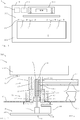
- the Figure 1 shows a cooking device according to the invention, which is designed here as an oven 10 with a microwave function or as a combination device.
- the cooking device 1 is provided here as a built-in device. However, it is also possible for the cooking appliance 1 to be designed as a stove or free-standing appliance.
- the cooking device 1 has a heatable cooking space 2 which can be closed by a door 104.
- heating sources and in particular electrical resistance heating sources are available for heating the cooking space 2.
- the cooking space can be heated with a convection heating source, with top heat and / or bottom heat, in hot air mode and / or with a grill function.
- 2 heating elements 21 are shown in a sectional representation in the upper region of the cooking space. In the view shown here, the heating elements 21 are covered by the closed door 104.
- the heating elements 21 shown here are, for example, an upper heat source and a grill heat source.
- the heating elements 21 each comprise several bends, so that there is a tortuous arrangement.
- a high-frequency generator 11 is provided for heating food to be cooked in the cooking chamber 2 by high-frequency radiation, for example in the frequency range of microwaves.
- the high-frequency generator 11 is preferably based on semiconductor technology. However, it is also possible for the high-frequency generator 11 to be designed as a magnetron or to include one.
- the cooking device 1 also has a pyrolytic cleaning function in which the cooking space is heated to temperatures above 400 ° C. and for example 430 ° or more.
- An antenna device 300 with a plurality of antenna units 3 is provided here for coupling the high-frequency radiation into the cooking space 2.
- the antenna units 3 are at least partially exposed in the cooking space.
- a transmission / reception element 4 of the respective antenna unit 3, not shown here, is exposed in the cooking space 2.
- the antenna units 3 are arranged in different areas of the cooking space 2 than shown here.
- the arrangement and / or number of antenna units 3 is set to the size or geometry of the cooking space 2 and to the respective purposes, for example characterizing or heating food to be cooked.
- the antenna units 3 can also be used to receive high-frequency radiation from the cooking space 2, which radiation can be used, for example, to detect Scattering parameters can be used.
- the antenna units 3 can also receive and / or transmit measuring radiation with a considerably lower power than the high-frequency radiation provided for heating the food to be cooked.
- the high-frequency generator 11 is also provided for generating the measuring radiation. The measuring radiation is used, for example, to monitor the cooking process or to characterize the food to be cooked, and in particular is not used to heat the food to be cooked.
- the cooking device 1 here comprises an operating device 103, by means of which, for example, an operating mode and / or an automatic function can be selected and set.
- the control device 103 also includes a user interface and, for example, a display.
- the cooking device 1 comprises a control device 102 for controlling or regulating device functions.
- the control device 102 is also suitable and designed for controlling the high-frequency generator 11.
- the antenna units 3 are arranged here in one plane with the heating elements 21.
- the antenna units 3 are surrounded by the winding arrangement of the heating elements 21 or a heating element 21.
- a transmission / reception element 4, not shown here, of the respective antenna unit 3 is aligned in one plane with the heating elements 21.
- a minimum distance from the surrounding heating elements 21 is maintained when the antenna units 3 are arranged.
- the minimum distance is defined on the basis of a feed point 54 of the antenna unit 3, which is not shown here.
- the Figure 2 shows an antenna unit 3 mounted on a cooking space wall 12.
- the antenna unit 3 comprises a plug device 7 with two plug units 17, 27, which are connected to one another here as intended.
- the antenna unit 3 here comprises a transmitting / receiving element 4, from which the high-frequency radiation is coupled into the cooking chamber 2 or is coupled out of the cooking chamber 2.
- the transmitting / receiving element 4 is elongated or rod-shaped here and comprises a free-standing end section 24 and a grounded end section 34. Between the end sections 24, 34 there is an infeed point 54 at which an infeed web 14 for Feeding signals and / or power is arranged in the transmitting / receiving element 4.
- a grounding web 44 is assigned to the grounded end section 34.
- the grounding web 44 is formed here in one piece with the grounded end section 34.
- the transmitting / receiving element 4 is supplied here with an inner conductor 13 and an outer conductor 23 via a coaxial line 37.
- the plug device 7 with the two plug units 17, 27 is provided.
- a plug unit 27 designed as an angle plug 47 is connected to the coaxial line 37.
- the other connector unit 17 is made available by an antenna adapter 33.
- the transmitting / receiving element 4 is attached to the antenna adapter 33.
- the grounding web 44 here comprises a section which runs parallel to the transmitting / receiving element 4 and which is fastened in an electrically conductive manner to an adapter sleeve 331 of the antenna adapter 33.
- the antenna adapter 33 also provides an outer conductor 23 through the adapter sleeve 331, which is connected in an electrically conductive manner to the grounding web 44 or the grounded end section 34.
- the antenna adapter comprises an inner conductor 13 which extends as an extension of the feed web 14 through the antenna adapter 33.
- the inner conductor 13 or the feed web 14 is decoupled from the part of the antenna adapter 33 acting as the outer conductor 23 by an insulator 53.
- the adapter sleeve 331 is provided with an external thread and can be screwed to the cooking chamber wall 12 with a union nut 43.
- the Figure 3 shows the antenna adapter 33 mounted on a cooking space wall 12.
- the antenna adapter 33 is then attached by plugging in the Figure 4 shown connector unit 27 connected to the coaxial line 37.
- the plug unit 27 is plugged onto the antenna adapter 33, which also serves as the plug unit 17.
- a thermal insulation device 6 is provided here.
- the insulating device 6 interrupts the inner conductor 13 here between the antenna adapter 33 and the plug unit 27.
- the insulating device 6 comprises an insulating layer 46 which concentrically surrounds the inner conductor 13 of the antenna adapter 33. This results in heat transfer from the inner conductor 13 of the antenna adapter 33 to the inner conductor 13 of the coaxial line 37 counteracted effectively.
- the insulating layer 46 is designed here as a glass sleeve into which the inner conductor 13 of the antenna adapter 33 extends.
- a coupling device 16 is provided here.
- the interrupted inner conductor is capacitively bridged by the coupling device 16.
- the coupling device 16 here comprises a metallic coupling sleeve 56, which concentrically surrounds the inner conductor 13 of the antenna adapter and the insulating layer 46.
- the inner conductor 13 of the coaxial line 37 is electrically conductively connected to the coupling sleeve 56.
- the insulating device 6 and the coupling device 16 are assigned to the plug unit 27 to which the coaxial line 37 is connected or which is plugged onto the antenna adapter 33.
- the glass sleeve of the insulating layer 46 and the coupling sleeve 56 are connected to one another and attached to the plug unit 27.
- the geometrical dimensions of the coupling device 16 and in particular the coupling sleeve 56 are designed in accordance with the operating frequency and the dielectric constant of the insulating layer 46 or the glass tube.
- a heat conducting element 5 is assigned to the antenna unit 3 here.
- the heat-conducting element 5 is conductively connected to the outer conductor 23 of the plug unit 27 of the coaxial line 37. By contacting the other plug unit 17, the heat is passed on from the regions of the antenna adapter 33 serving as outer conductor 23 to the heat-conducting element 5.
- the heat-conducting element 5 is thermally conductively connected to a cooled device component 101.
- the device component 101 is at the lowest possible temperature level, so that reliable heat transfer in the direction of the device component 101 is achieved.
- the device component 101 is, for example, an active or airflow-cooled electronic component of the cooking device 1.
- the device component 101 comprises a housing to which the heat-conducting element 5 is connected.
- the heat-conducting element 5 is here in the form of a plate, so that the surface effective for the heat transfer is advantageously enlarged.
- the heat-conducting element 5 is designed as a coupling plate 15.
- the heat-conducting element 5 is attached to the plug unit 27 here. A particularly uncomplicated alignment of the heat-conducting element 5 takes place already when the plug connection is made.
- the one in the Figure 8 Shown embodiment of the heat-conducting element 5 as a coupling plate 15 with a through opening.
- the heat conducting element 5 can be screwed to the plug unit 27 through the through opening, for example by means of a screw 25.
- a cooking space insulation 105 is arranged to avoid heat losses.
- the oven insulation 105 is in the Figure 2 shown strongly schematically and has been left out for better clarity in the area of the antenna unit 3.
- a fiber material is used for this.
- the thickness of the cooking space insulation 105 is in particular between 10 mm and 30 mm and for example 20 mm. Thinner or stronger cooking chamber insulation 105 is also possible.
- the adapter sleeve 331 of the antenna adapter 33 extends here through the cooking space insulation 105.
- the part of the antenna adapter 33 designed as a plug unit 17 is preferably outside the cooking space insulation 105.
- the plug unit 27 and the coaxial line 37 connected to it are also outside the cooking space insulation 105.
- the heat-conducting element 5 and the associated device component 101 are preferably also arranged.
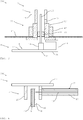
- the antenna unit 3 is shown in a perspective view with a view of the transmitting / receiving element 4.
- the geometry of the transmitting / receiving element 4 and its attachment to the antenna adapter 33 can be seen particularly well here.
- the free-standing end section 24 of the transmission / reception element 4 here comprises a bend 8, as a result of which the extent of the transmission / reception element 4 can be reduced without the length of the transmission / reception element 4 necessary or advantageous for the desired frequency range being adversely affected .
- the bend 8 is hook-shaped here.
- the bend 8 can also have a different geometry.
- the bend 8 can be formed, for example, in an S-shape or with further bends.
- the bend 8 is preferably carried out such that the free-standing end section 24 is at a minimum distance from other components of the cooking space 2 and, for example, from adjacent heating elements 21.
- the geometry of the bend 8 for example, depending on the positioning of the antenna unit 3 in the cooking space 2.
- the bend 8 shown here runs in one plane.
- the plane extends parallel to a cooking chamber wall 12, not shown here, on which the antenna unit 3 is arranged in an assembled state of the cooking device 1.
- the cooking space wall 12 extends in particular transversely to the adapter sleeve 331, so that the adapter sleeve 331 can be fixed to the cooking space wall 12 by means of the union nut 43.
- the plane in which the bend 8 extends also extends, in particular, transversely to a section of the grounding web 44.
- the bend 8 also runs in a plane with the surrounding heating elements 21. This is a particularly space-saving arrangement the antenna unit 3 possible.
- An arrangement in which the transmitting / receiving element 4 or the bend 8 lie in one plane with the heating element 21 is, for example, in FIG Figure 1 represented very schematically.
- the transmitting / receiving element 4 is formed in one piece here.
- the inner conductor 13 is formed here by an extension of the feed web 14. For example, the inner conductor 13 is inserted in the area of the antenna adapter 33 into a bore in the feed bar 14 and fastened to the feed point 54.
- the grounding web 44 here comprises a section which runs parallel to the transmitting / receiving element 4 or to the grounded end section 34 and which is contacted on the antenna adapter 33.
- the grounding web 44 is connected to the adapter sleeve 331 in an electrically conductive manner.
- the adapter sleeve 331 merges into the outer conductor 23 of the plug unit 17, so that the grounded end section 34 is in contact with the outer conductor 23 via the grounding bar 44 and the adapter sleeve 331.
- the Figure 6 shows the antenna unit 3 of FIG Figure 5 in a side view, in which the transmitting / receiving element 4 is oriented downwards.
- the upper part of the antenna adapter 33 is shown here partly in section, so that the inner conductor 13 lying within the antenna adapter 33 can be clearly seen.
- the inner conductor 13 is inserted into the insulating layer 46 designed as a glass sleeve.
- the coupling sleeve 56 and the inner conductor 13 of the coaxial line 37 connected thereto the two interrupted ends of the inner conductor 13 are capacitively coupled to one another when they are plugged together.
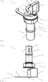
- the plug unit 27 and the coaxial line 37 connected to it are shown in perspective.
- the heat-conducting element 5 designed as a coupling plate 15 is fastened here to the plug unit 27.
- the thermal insulation device 6 is integrated in the plug unit 27, into which the inner conductor 13 (not visible here) extends.
- the coupling sleeve 56 of the coupling device 16 protrudes from the plug unit 27.
- the insulating layer 46 and, for example, a glass sleeve are not visible here within the coupling sleeve 56.
- the Figure 8 shows the plug unit 27 of the Figure 7 in a side view.
- the heat-conducting element 5 and the screw 25 used to fasten the heat-conducting element 5 to the plug unit 27 are shown in an exploded view.
- the coupling plate 15 is conductively connected to the plug unit 27 by the screw 25. After plugging together with the plug unit 17 of the antenna adapter 33, the heat absorbed in the cooking space 2 can be dissipated to the coupling plate 15 and from there to the device component 101, not shown here.
- Such a plug device 7 has the advantage that a reliable and robust and at the same time detachable connection can be established between the transmitting / receiving element 4 in the cooking space 2 and the coaxial line 37 connected to it. It is particularly advantageous that no metallic spring elements are provided for this, which can often only be carried out with very expensive materials in the temperature range of a cooking appliance 1.
- the connector device 7 presented here thus enables a correspondingly low-resistance and durable connection which is structurally inexpensive and economical to manufacture. This is particularly advantageous if correspondingly high transmission powers have to be transmitted, for example for heating food.
- the temperature in the cooking space 2 is, for example, 430 ° C. Temperatures between 100 ° C. and 160 ° C. then occur in the interior of the cooking device 1 and outside the cooking chamber insulation 105 surrounding the cooking chamber 2 on.
- the actively cooled device component arranged inside the device then has, for example, temperatures between 80-100 ° C. on its outside of the housing.
- the conductors 13, 23 of the coaxial line 37 are at a comparable temperature level as the device component 101. For example, temperatures between 80-100 ° C. occur in or on the coaxial line 37. Without the use of the insulating device 6 and / or the heat-conducting element 5, the heat from the cooking space 2 would be undesirably transferred to the coaxial line 37. This would also result in very unfavorable temperatures above 200 ° C and, for example, 300 ° C or more.
- a conventional high-frequency coaxial line 37 can thus be used through the heat-conducting element 5 and / or the insulating device 6, without critical temperatures occurring in or on the line 37 in a heated cooking chamber 2.
Landscapes
- Physics & Mathematics (AREA)
- Electromagnetism (AREA)
- Constitution Of High-Frequency Heating (AREA)
- Electric Stoves And Ranges (AREA)
Claims (14)
- Appareil de cuisson (1) comportant au moins une chambre de cuisson (2) pouvant être chauffée et au moins un dispositif d'antenne (300) dotée d'au moins une unité d'antenne (3) pour l'émission et/ou la réception d'un rayonnement haute fréquence dans la chambre de cuisson (2) ou à partir de la chambre de cuisson (2), l'unité d'antenne (3) comprenant au moins un élément d'émission/de réception (4) et au moins un conducteur (13, 23) relié à l'élément d'émission/de réception, le conducteur (13, 23) étant relié par conduction thermique à au moins un composant d'appareil (101) par au moins un élément conducteur de chaleur (5) pour augmenter une surface efficace pour le transfert de chaleur, de sorte que la chaleur peut être dissipée du conducteur (13, 23) par l'intermédiaire de l'élément conducteur de chaleur (5) au composant d'appareil (101),
caractérisé en ce que
le conducteur (13, 23) est interrompu par au moins un dispositif d'isolation thermique (6), en ce que l'interruption est pontée de manière capacitive au moyen d'un dispositif de couplage (16), de sorte que les signaux et/ou la puissance peut(vent) être transmis(e) par l'intermédiaire du conducteur (13, 23) interrompu, en ce que, dans la région du dispositif d'isolation (6), une extrémité du conducteur (13, 23) interrompu est entourée d'une couche isolante (46), et en ce que la couche isolante (46) est entourée d'un manchon de couplage (56) électriquement conducteur auquel une autre extrémité du conducteur interrompu (13, 23) est reliée. - Appareil de cuisson (1) selon la revendication 1, caractérisé en ce que l'unité d'antenne (3) comprend au moins deux conducteurs (13, 23) qui fournissent au moins un conducteur intérieur (13) et au moins un conducteur extérieur (23), et en ce que l'élément conducteur de chaleur (5) est associé au conducteur extérieur (23) et/ou le dispositif d'isolation thermique (6) est associé au conducteur intérieur (13).
- Appareil de cuisson (1) selon l'une des revendications 1 ou 2, caractérisé en ce que la couche isolante (46) est formée d'un matériau en verre et/ou le manchon de couplage (56) est formé d'un matériau métallique.
- Appareil de cuisson (1) selon l'une des revendications précédentes, caractérisé en ce que le dispositif d'isolation (6) est associé à un dispositif d'emboîtement (7) comportant deux unités d'emboîtement pouvant être reliées l'une à l'autre de façon amovible (17, 27), et en ce que la couche isolante (46) et/ou le manchon de couplage (56) est disposé(e) dans l'une des deux unités d'emboîtement (17, 27) et peut être glissé(e) sur une extrémité du conducteur (13, 23) par emboîtement des unités d'emboîtement (17, 27).
- Appareil de cuisson (1) selon la revendication 4, caractérisé en ce que l'une des deux unités d'emboîtement (17, 27) est fournie par un adaptateur d'antenne (33) auquel est fixé l'élément d'émission/de réception (4), et est montée dans la chambre de cuisson (2), et en ce que le conducteur (13, 23), notamment le conducteur intérieur (13), est formé dans l'adaptateur d'antenne (33) par un prolongement d'une barrette d'alimentation (14) de l'élément d'émission/de réception (4) et/ou en ce que le conducteur (13, 23), notamment le conducteur extérieur (23), est fourni sur l'adaptateur d'antenne (33) par un manchon d'adaptateur (331) pouvant être monté sur une paroi de chambre de cuisson (12).
- Appareil de cuisson (1) selon la revendication 4 ou 5, caractérisé en ce que l'une des deux unités d'emboîtement (17, 27) est reliée à une ligne coaxiale (37).
- Appareil de cuisson (1) selon l'une des revendications précédentes, caractérisé en ce que l'élément conducteur de chaleur (5) est relié par conduction à un composant d'appareil (101) activement refroidi.
- Appareil de cuisson (1) selon l'une des revendications précédentes, caractérisé en ce que l'élément conducteur de chaleur (5) est disposé à l'extérieur de la chambre de cuisson (2).
- Appareil de cuisson (1) selon l'une des revendications précédentes, caractérisé en ce que l'élément conducteur de chaleur (5) est réalisé en forme de plaque.
- Appareil de cuisson (1) selon l'une des revendications précédentes, caractérisé en ce que l'élément conducteur de chaleur (5) est associé à un dispositif d'emboîtement (7) comportant deux unités d'emboîtement (17, 27) pouvant être reliées l'une à l'autre de façon amovible, et en ce que l'élément conducteur de chaleur (5) est fixé à l'une des unités d'emboîtement (17, 27).
- Appareil de cuisson (1) selon la revendication 10, caractérisé en ce que l'élément conducteur de chaleur (5) est fixé à une unité d'emboîtement (17, 27) réalisée sous forme de connecteur coudé (47).
- Appareil de cuisson (1) selon l'une des revendications précédentes, caractérisé en ce que l'élément d'émission/de réception (4) comprend une section d'extrémité (24) librement saillante et une section d'extrémité (34) mise à la terre, laquelle comporte une barrette de mise à la terre (44), en ce qu'une barrette d'alimentation (14) est disposée entre les sections d'extrémité (24, 34), et en ce que la barrette d'alimentation (14) et la barrette de mise à la terre (44) s'étendent transversalement à l'élément d'émission/de réception (4), de sorte que l'on obtienne, suivant une vue latérale, une structure en forme de F de l'unité d'antenne (3).
- Appareil de cuisson (1) selon l'une des revendications précédentes, caractérisé en ce qu'il (1) comprend au moins un générateur haute fréquence (11), en ce que les aliments à cuire peuvent être chauffés par rayonnement haute fréquence dans la chambre de cuisson (2), au moyen du générateur haute fréquence (11), et en ce que l'unité d'antenne (3) est adaptée et conçue pour émettre, dans la chambre de cuisson (2), le rayonnement haute fréquence prévu pour le chauffage.
- Appareil de cuisson (1) selon l'une des revendications précédentes, caractérisé en ce qu'il (1) est adapté et conçu pour être nettoyé par pyrolyse.
Priority Applications (1)
| Application Number | Priority Date | Filing Date | Title |
|---|---|---|---|
| PL17190024T PL3310129T3 (pl) | 2016-10-11 | 2017-09-08 | Urządzenie do gotowania |
Applications Claiming Priority (1)
| Application Number | Priority Date | Filing Date | Title |
|---|---|---|---|
| DE102016119286.4A DE102016119286B4 (de) | 2016-10-11 | 2016-10-11 | Gargerät |
Publications (2)
| Publication Number | Publication Date |
|---|---|
| EP3310129A1 EP3310129A1 (fr) | 2018-04-18 |
| EP3310129B1 true EP3310129B1 (fr) | 2020-08-05 |
Family
ID=59829255
Family Applications (1)
| Application Number | Title | Priority Date | Filing Date |
|---|---|---|---|
| EP17190024.4A Active EP3310129B1 (fr) | 2016-10-11 | 2017-09-08 | Appareil de cuisson |
Country Status (3)
| Country | Link |
|---|---|
| EP (1) | EP3310129B1 (fr) |
| DE (1) | DE102016119286B4 (fr) |
| PL (1) | PL3310129T3 (fr) |
Families Citing this family (1)
| Publication number | Priority date | Publication date | Assignee | Title |
|---|---|---|---|---|
| CN111417226B (zh) * | 2019-01-04 | 2025-02-28 | 海尔智家股份有限公司 | 加热装置 |
Family Cites Families (8)
| Publication number | Priority date | Publication date | Assignee | Title |
|---|---|---|---|---|
| JPS51145038A (en) * | 1975-06-09 | 1976-12-13 | Toshiba Corp | Microwave oven |
| US4028521A (en) * | 1976-02-26 | 1977-06-07 | Roper Corporation | Antenna construction for microwave oven |
| CA1125378A (fr) * | 1978-04-03 | 1982-06-08 | Bernard J. Weiss | Systeme de commandes pour four auto-nettoyant four a micro-ondes combines |
| JPS5514688A (en) | 1978-07-18 | 1980-02-01 | Matsushita Electric Industrial Co Ltd | High frequency heater |
| DE3034050C2 (de) * | 1980-09-10 | 1983-06-23 | Bosch-Siemens Hausgeräte GmbH, 7000 Stuttgart | Kupplung zwischen der Abtriebswelle des Antriebes und dem etwa in deren Verlängerung angeordneten rotierenden Antennenschaft eines Mikrowellenofens |
| JP4899595B2 (ja) | 2006-04-07 | 2012-03-21 | パナソニック株式会社 | マイクロ波発生装置 |
| DE102007055548B4 (de) * | 2007-11-21 | 2013-05-08 | Baerlocher Gmbh | Vorrichtung zum Eintrag von Mikrowellen in einen Reaktionsraum |
| DE102014226280B4 (de) * | 2014-12-17 | 2019-06-13 | E.G.O. Elektro-Gerätebau GmbH | Mikrowellengenerator und Mikrowellenofen |
-
2016
- 2016-10-11 DE DE102016119286.4A patent/DE102016119286B4/de not_active Expired - Fee Related
-
2017
- 2017-09-08 PL PL17190024T patent/PL3310129T3/pl unknown
- 2017-09-08 EP EP17190024.4A patent/EP3310129B1/fr active Active
Non-Patent Citations (1)
| Title |
|---|
| None * |
Also Published As
| Publication number | Publication date |
|---|---|
| DE102016119286B4 (de) | 2020-06-10 |
| EP3310129A1 (fr) | 2018-04-18 |
| PL3310129T3 (pl) | 2021-01-11 |
| DE102016119286A1 (de) | 2018-04-12 |
Similar Documents
| Publication | Publication Date | Title |
|---|---|---|
| DE102017111319A1 (de) | Einrichtung zur Erzeugung und Transmission von Hochfrequenzwellen (HF-Wellen) | |
| EP3035773B2 (fr) | Generateur de micro-ondes et four a micro-ondes | |
| EP2966935B1 (fr) | Appareil de cuisson et système de fixation | |
| DE3300677A1 (de) | Applikator zum zu- und abfuehren von hochfrequenzenergie | |
| EP3310129B1 (fr) | Appareil de cuisson | |
| EP1258172B1 (fr) | Surface de cuisson avec capteur de temperature | |
| EP2489095B1 (fr) | Coupleur d'antenne | |
| DE20202906U1 (de) | Beheizbare Leitung | |
| EP2037181B1 (fr) | Appareil ménager doté d'un espace de traitement et d'une antenne en forme de tige | |
| DE102011109163B4 (de) | Ofen mit Abfrageantenne | |
| EP2663160B1 (fr) | Appareil ménager | |
| EP2187700B1 (fr) | Appareil de cuisson et procédé d'alimentation en micro-ondes dans la chambre interne d'un appareil de cuisson | |
| EP1795989B1 (fr) | Appareil ménager doté d'une commande électrique et d'un accessoire | |
| EP3897074A1 (fr) | Module de chauffage à ondes à haute fréquence | |
| EP3729486B1 (fr) | Système de contrôle thermique homogène électriquement découplé d'une électrode au moyen de tubes thermoconducteurs et installation de traitement comprenant ledit système | |
| DE102015109685B4 (de) | Gargerät mit einer Mikrowellenquelle sowie Antenne für ein Gargerät | |
| DE102017114987B3 (de) | Messsonde und Gargerät mit einer solchen Messsonde | |
| EP3643141A1 (fr) | Appareil de cuisson à micro-ondes à antenne planaire | |
| EP2187703B1 (fr) | Appareil de cuisson doté d'une alimentation à micro-ondes | |
| BE1030943B1 (de) | Hochfrequenz-Haushaltsgerät, vorzugsweise Hochfrequenz-Gargerät | |
| EP4539601A1 (fr) | Capteur de température nucléaire, appareil de cuisson avec capteur de température nucléaire et piège à micro-ondes | |
| EP3815464A1 (fr) | Four à micro-ondes électro-ménager et procédé pour la fabrication d'un guide de micro-ondes | |
| DE102020125734B4 (de) | Gargerät, umfassend einen Garraum zur Wärmebehandlung eines Garguts mit Mikrowellen | |
| DE102017201767B4 (de) | Mikrowellengerät | |
| WO2024074291A1 (fr) | Appareil ménager haute fréquence, de préférence appareil de cuisson haute fréquence |
Legal Events
| Date | Code | Title | Description |
|---|---|---|---|
| PUAI | Public reference made under article 153(3) epc to a published international application that has entered the european phase |
Free format text: ORIGINAL CODE: 0009012 |
|
| STAA | Information on the status of an ep patent application or granted ep patent |
Free format text: STATUS: THE APPLICATION HAS BEEN PUBLISHED |
|
| AK | Designated contracting states |
Kind code of ref document: A1 Designated state(s): AL AT BE BG CH CY CZ DE DK EE ES FI FR GB GR HR HU IE IS IT LI LT LU LV MC MK MT NL NO PL PT RO RS SE SI SK SM TR |
|
| AX | Request for extension of the european patent |
Extension state: BA ME |
|
| STAA | Information on the status of an ep patent application or granted ep patent |
Free format text: STATUS: REQUEST FOR EXAMINATION WAS MADE |
|
| 17P | Request for examination filed |
Effective date: 20181018 |
|
| RBV | Designated contracting states (corrected) |
Designated state(s): AL AT BE BG CH CY CZ DE DK EE ES FI FR GB GR HR HU IE IS IT LI LT LU LV MC MK MT NL NO PL PT RO RS SE SI SK SM TR |
|
| GRAP | Despatch of communication of intention to grant a patent |
Free format text: ORIGINAL CODE: EPIDOSNIGR1 |
|
| STAA | Information on the status of an ep patent application or granted ep patent |
Free format text: STATUS: GRANT OF PATENT IS INTENDED |
|
| RIC1 | Information provided on ipc code assigned before grant |
Ipc: H05B 6/72 20060101AFI20200311BHEP Ipc: H05B 6/64 20060101ALI20200311BHEP |
|
| INTG | Intention to grant announced |
Effective date: 20200330 |
|
| GRAS | Grant fee paid |
Free format text: ORIGINAL CODE: EPIDOSNIGR3 |
|
| GRAA | (expected) grant |
Free format text: ORIGINAL CODE: 0009210 |
|
| STAA | Information on the status of an ep patent application or granted ep patent |
Free format text: STATUS: THE PATENT HAS BEEN GRANTED |
|
| AK | Designated contracting states |
Kind code of ref document: B1 Designated state(s): AL AT BE BG CH CY CZ DE DK EE ES FI FR GB GR HR HU IE IS IT LI LT LU LV MC MK MT NL NO PL PT RO RS SE SI SK SM TR |
|
| REG | Reference to a national code |
Ref country code: GB Ref legal event code: FG4D Free format text: NOT ENGLISH |
|
| REG | Reference to a national code |
Ref country code: DE Ref legal event code: R084 Ref document number: 502017006523 Country of ref document: DE |
|
| REG | Reference to a national code |
Ref country code: CH Ref legal event code: EP |
|
| REG | Reference to a national code |
Ref country code: AT Ref legal event code: REF Ref document number: 1300555 Country of ref document: AT Kind code of ref document: T Effective date: 20200815 |
|
| REG | Reference to a national code |
Ref country code: DE Ref legal event code: R096 Ref document number: 502017006523 Country of ref document: DE |
|
| REG | Reference to a national code |
Ref country code: IE Ref legal event code: FG4D Free format text: LANGUAGE OF EP DOCUMENT: GERMAN |
|
| REG | Reference to a national code |
Ref country code: GB Ref legal event code: 746 Effective date: 20200916 |
|
| REG | Reference to a national code |
Ref country code: LT Ref legal event code: MG4D |
|
| REG | Reference to a national code |
Ref country code: NL Ref legal event code: MP Effective date: 20200805 |
|
| PG25 | Lapsed in a contracting state [announced via postgrant information from national office to epo] |
Ref country code: LT Free format text: LAPSE BECAUSE OF FAILURE TO SUBMIT A TRANSLATION OF THE DESCRIPTION OR TO PAY THE FEE WITHIN THE PRESCRIBED TIME-LIMIT Effective date: 20200805 Ref country code: HR Free format text: LAPSE BECAUSE OF FAILURE TO SUBMIT A TRANSLATION OF THE DESCRIPTION OR TO PAY THE FEE WITHIN THE PRESCRIBED TIME-LIMIT Effective date: 20200805 Ref country code: BG Free format text: LAPSE BECAUSE OF FAILURE TO SUBMIT A TRANSLATION OF THE DESCRIPTION OR TO PAY THE FEE WITHIN THE PRESCRIBED TIME-LIMIT Effective date: 20201105 Ref country code: ES Free format text: LAPSE BECAUSE OF FAILURE TO SUBMIT A TRANSLATION OF THE DESCRIPTION OR TO PAY THE FEE WITHIN THE PRESCRIBED TIME-LIMIT Effective date: 20200805 Ref country code: PT Free format text: LAPSE BECAUSE OF FAILURE TO SUBMIT A TRANSLATION OF THE DESCRIPTION OR TO PAY THE FEE WITHIN THE PRESCRIBED TIME-LIMIT Effective date: 20201207 Ref country code: NO Free format text: LAPSE BECAUSE OF FAILURE TO SUBMIT A TRANSLATION OF THE DESCRIPTION OR TO PAY THE FEE WITHIN THE PRESCRIBED TIME-LIMIT Effective date: 20201105 Ref country code: SE Free format text: LAPSE BECAUSE OF FAILURE TO SUBMIT A TRANSLATION OF THE DESCRIPTION OR TO PAY THE FEE WITHIN THE PRESCRIBED TIME-LIMIT Effective date: 20200805 Ref country code: GR Free format text: LAPSE BECAUSE OF FAILURE TO SUBMIT A TRANSLATION OF THE DESCRIPTION OR TO PAY THE FEE WITHIN THE PRESCRIBED TIME-LIMIT Effective date: 20201106 Ref country code: FI Free format text: LAPSE BECAUSE OF FAILURE TO SUBMIT A TRANSLATION OF THE DESCRIPTION OR TO PAY THE FEE WITHIN THE PRESCRIBED TIME-LIMIT Effective date: 20200805 |
|
| PG25 | Lapsed in a contracting state [announced via postgrant information from national office to epo] |
Ref country code: RS Free format text: LAPSE BECAUSE OF FAILURE TO SUBMIT A TRANSLATION OF THE DESCRIPTION OR TO PAY THE FEE WITHIN THE PRESCRIBED TIME-LIMIT Effective date: 20200805 Ref country code: NL Free format text: LAPSE BECAUSE OF FAILURE TO SUBMIT A TRANSLATION OF THE DESCRIPTION OR TO PAY THE FEE WITHIN THE PRESCRIBED TIME-LIMIT Effective date: 20200805 Ref country code: LV Free format text: LAPSE BECAUSE OF FAILURE TO SUBMIT A TRANSLATION OF THE DESCRIPTION OR TO PAY THE FEE WITHIN THE PRESCRIBED TIME-LIMIT Effective date: 20200805 Ref country code: IS Free format text: LAPSE BECAUSE OF FAILURE TO SUBMIT A TRANSLATION OF THE DESCRIPTION OR TO PAY THE FEE WITHIN THE PRESCRIBED TIME-LIMIT Effective date: 20201205 |
|
| PG25 | Lapsed in a contracting state [announced via postgrant information from national office to epo] |
Ref country code: RO Free format text: LAPSE BECAUSE OF FAILURE TO SUBMIT A TRANSLATION OF THE DESCRIPTION OR TO PAY THE FEE WITHIN THE PRESCRIBED TIME-LIMIT Effective date: 20200805 Ref country code: DK Free format text: LAPSE BECAUSE OF FAILURE TO SUBMIT A TRANSLATION OF THE DESCRIPTION OR TO PAY THE FEE WITHIN THE PRESCRIBED TIME-LIMIT Effective date: 20200805 Ref country code: CZ Free format text: LAPSE BECAUSE OF FAILURE TO SUBMIT A TRANSLATION OF THE DESCRIPTION OR TO PAY THE FEE WITHIN THE PRESCRIBED TIME-LIMIT Effective date: 20200805 Ref country code: EE Free format text: LAPSE BECAUSE OF FAILURE TO SUBMIT A TRANSLATION OF THE DESCRIPTION OR TO PAY THE FEE WITHIN THE PRESCRIBED TIME-LIMIT Effective date: 20200805 Ref country code: SM Free format text: LAPSE BECAUSE OF FAILURE TO SUBMIT A TRANSLATION OF THE DESCRIPTION OR TO PAY THE FEE WITHIN THE PRESCRIBED TIME-LIMIT Effective date: 20200805 |
|
| REG | Reference to a national code |
Ref country code: CH Ref legal event code: PL |
|
| REG | Reference to a national code |
Ref country code: DE Ref legal event code: R097 Ref document number: 502017006523 Country of ref document: DE |
|
| PG25 | Lapsed in a contracting state [announced via postgrant information from national office to epo] |
Ref country code: MC Free format text: LAPSE BECAUSE OF FAILURE TO SUBMIT A TRANSLATION OF THE DESCRIPTION OR TO PAY THE FEE WITHIN THE PRESCRIBED TIME-LIMIT Effective date: 20200805 Ref country code: AL Free format text: LAPSE BECAUSE OF FAILURE TO SUBMIT A TRANSLATION OF THE DESCRIPTION OR TO PAY THE FEE WITHIN THE PRESCRIBED TIME-LIMIT Effective date: 20200805 |
|
| PLBE | No opposition filed within time limit |
Free format text: ORIGINAL CODE: 0009261 |
|
| STAA | Information on the status of an ep patent application or granted ep patent |
Free format text: STATUS: NO OPPOSITION FILED WITHIN TIME LIMIT |
|
| REG | Reference to a national code |
Ref country code: BE Ref legal event code: MM Effective date: 20200930 |
|
| PG25 | Lapsed in a contracting state [announced via postgrant information from national office to epo] |
Ref country code: LU Free format text: LAPSE BECAUSE OF NON-PAYMENT OF DUE FEES Effective date: 20200908 Ref country code: SK Free format text: LAPSE BECAUSE OF FAILURE TO SUBMIT A TRANSLATION OF THE DESCRIPTION OR TO PAY THE FEE WITHIN THE PRESCRIBED TIME-LIMIT Effective date: 20200805 |
|
| 26N | No opposition filed |
Effective date: 20210507 |
|
| PG25 | Lapsed in a contracting state [announced via postgrant information from national office to epo] |
Ref country code: BE Free format text: LAPSE BECAUSE OF NON-PAYMENT OF DUE FEES Effective date: 20200930 Ref country code: CH Free format text: LAPSE BECAUSE OF NON-PAYMENT OF DUE FEES Effective date: 20200930 Ref country code: SI Free format text: LAPSE BECAUSE OF FAILURE TO SUBMIT A TRANSLATION OF THE DESCRIPTION OR TO PAY THE FEE WITHIN THE PRESCRIBED TIME-LIMIT Effective date: 20200805 Ref country code: IE Free format text: LAPSE BECAUSE OF NON-PAYMENT OF DUE FEES Effective date: 20200908 Ref country code: LI Free format text: LAPSE BECAUSE OF NON-PAYMENT OF DUE FEES Effective date: 20200930 |
|
| PG25 | Lapsed in a contracting state [announced via postgrant information from national office to epo] |
Ref country code: MT Free format text: LAPSE BECAUSE OF FAILURE TO SUBMIT A TRANSLATION OF THE DESCRIPTION OR TO PAY THE FEE WITHIN THE PRESCRIBED TIME-LIMIT Effective date: 20200805 Ref country code: CY Free format text: LAPSE BECAUSE OF FAILURE TO SUBMIT A TRANSLATION OF THE DESCRIPTION OR TO PAY THE FEE WITHIN THE PRESCRIBED TIME-LIMIT Effective date: 20200805 |
|
| PG25 | Lapsed in a contracting state [announced via postgrant information from national office to epo] |
Ref country code: MK Free format text: LAPSE BECAUSE OF FAILURE TO SUBMIT A TRANSLATION OF THE DESCRIPTION OR TO PAY THE FEE WITHIN THE PRESCRIBED TIME-LIMIT Effective date: 20200805 |
|
| P01 | Opt-out of the competence of the unified patent court (upc) registered |
Effective date: 20230528 |
|
| REG | Reference to a national code |
Ref country code: AT Ref legal event code: MM01 Ref document number: 1300555 Country of ref document: AT Kind code of ref document: T Effective date: 20220908 |
|
| PG25 | Lapsed in a contracting state [announced via postgrant information from national office to epo] |
Ref country code: AT Free format text: LAPSE BECAUSE OF NON-PAYMENT OF DUE FEES Effective date: 20220908 |
|
| PGFP | Annual fee paid to national office [announced via postgrant information from national office to epo] |
Ref country code: DE Payment date: 20250930 Year of fee payment: 9 |
|
| PGFP | Annual fee paid to national office [announced via postgrant information from national office to epo] |
Ref country code: PL Payment date: 20250825 Year of fee payment: 9 Ref country code: IT Payment date: 20250922 Year of fee payment: 9 Ref country code: TR Payment date: 20250826 Year of fee payment: 9 |
|
| PGFP | Annual fee paid to national office [announced via postgrant information from national office to epo] |
Ref country code: GB Payment date: 20250923 Year of fee payment: 9 |
|
| PGFP | Annual fee paid to national office [announced via postgrant information from national office to epo] |
Ref country code: FR Payment date: 20250925 Year of fee payment: 9 |