EP3311779B1 - Valve cardiaque - Google Patents
Valve cardiaque Download PDFInfo
- Publication number
- EP3311779B1 EP3311779B1 EP17206130.1A EP17206130A EP3311779B1 EP 3311779 B1 EP3311779 B1 EP 3311779B1 EP 17206130 A EP17206130 A EP 17206130A EP 3311779 B1 EP3311779 B1 EP 3311779B1
- Authority
- EP
- European Patent Office
- Prior art keywords
- stent
- valve
- degree
- component
- section
- Prior art date
- Legal status (The legal status is an assumption and is not a legal conclusion. Google has not performed a legal analysis and makes no representation as to the accuracy of the status listed.)
- Active
Links
Images



Classifications
-
- A—HUMAN NECESSITIES
- A61—MEDICAL OR VETERINARY SCIENCE; HYGIENE
- A61F—FILTERS IMPLANTABLE INTO BLOOD VESSELS; PROSTHESES; DEVICES PROVIDING PATENCY TO, OR PREVENTING COLLAPSING OF, TUBULAR STRUCTURES OF THE BODY, e.g. STENTS; ORTHOPAEDIC, NURSING OR CONTRACEPTIVE DEVICES; FOMENTATION; TREATMENT OR PROTECTION OF EYES OR EARS; BANDAGES, DRESSINGS OR ABSORBENT PADS; FIRST-AID KITS
- A61F2/00—Filters implantable into blood vessels; Prostheses, i.e. artificial substitutes or replacements for parts of the body; Appliances for connecting them with the body; Devices providing patency to, or preventing collapsing of, tubular structures of the body, e.g. stents
- A61F2/02—Prostheses implantable into the body
- A61F2/24—Heart valves ; Vascular valves, e.g. venous valves; Heart implants, e.g. passive devices for improving the function of the native valve or the heart muscle; Transmyocardial revascularisation [TMR] devices; Valves implantable in the body
- A61F2/2412—Heart valves ; Vascular valves, e.g. venous valves; Heart implants, e.g. passive devices for improving the function of the native valve or the heart muscle; Transmyocardial revascularisation [TMR] devices; Valves implantable in the body with soft flexible valve members, e.g. tissue valves shaped like natural valves
- A61F2/2418—Scaffolds therefor, e.g. support stents
-
- A—HUMAN NECESSITIES
- A61—MEDICAL OR VETERINARY SCIENCE; HYGIENE
- A61F—FILTERS IMPLANTABLE INTO BLOOD VESSELS; PROSTHESES; DEVICES PROVIDING PATENCY TO, OR PREVENTING COLLAPSING OF, TUBULAR STRUCTURES OF THE BODY, e.g. STENTS; ORTHOPAEDIC, NURSING OR CONTRACEPTIVE DEVICES; FOMENTATION; TREATMENT OR PROTECTION OF EYES OR EARS; BANDAGES, DRESSINGS OR ABSORBENT PADS; FIRST-AID KITS
- A61F2/00—Filters implantable into blood vessels; Prostheses, i.e. artificial substitutes or replacements for parts of the body; Appliances for connecting them with the body; Devices providing patency to, or preventing collapsing of, tubular structures of the body, e.g. stents
- A61F2/02—Prostheses implantable into the body
- A61F2/24—Heart valves ; Vascular valves, e.g. venous valves; Heart implants, e.g. passive devices for improving the function of the native valve or the heart muscle; Transmyocardial revascularisation [TMR] devices; Valves implantable in the body
- A61F2/2427—Devices for manipulating or deploying heart valves during implantation
- A61F2/2436—Deployment by retracting a sheath
-
- A—HUMAN NECESSITIES
- A61—MEDICAL OR VETERINARY SCIENCE; HYGIENE
- A61F—FILTERS IMPLANTABLE INTO BLOOD VESSELS; PROSTHESES; DEVICES PROVIDING PATENCY TO, OR PREVENTING COLLAPSING OF, TUBULAR STRUCTURES OF THE BODY, e.g. STENTS; ORTHOPAEDIC, NURSING OR CONTRACEPTIVE DEVICES; FOMENTATION; TREATMENT OR PROTECTION OF EYES OR EARS; BANDAGES, DRESSINGS OR ABSORBENT PADS; FIRST-AID KITS
- A61F2220/00—Fixations or connections for prostheses classified in groups A61F2/00 - A61F2/26 or A61F2/82 or A61F9/00 or A61F11/00 or subgroups thereof
- A61F2220/0025—Connections or couplings between prosthetic parts, e.g. between modular parts; Connecting elements
- A61F2220/0075—Connections or couplings between prosthetic parts, e.g. between modular parts; Connecting elements sutured, ligatured or stitched, retained or tied with a rope, string, thread, wire or cable
-
- A—HUMAN NECESSITIES
- A61—MEDICAL OR VETERINARY SCIENCE; HYGIENE
- A61F—FILTERS IMPLANTABLE INTO BLOOD VESSELS; PROSTHESES; DEVICES PROVIDING PATENCY TO, OR PREVENTING COLLAPSING OF, TUBULAR STRUCTURES OF THE BODY, e.g. STENTS; ORTHOPAEDIC, NURSING OR CONTRACEPTIVE DEVICES; FOMENTATION; TREATMENT OR PROTECTION OF EYES OR EARS; BANDAGES, DRESSINGS OR ABSORBENT PADS; FIRST-AID KITS
- A61F2230/00—Geometry of prostheses classified in groups A61F2/00 - A61F2/26 or A61F2/82 or A61F9/00 or A61F11/00 or subgroups thereof
- A61F2230/0002—Two-dimensional shapes, e.g. cross-sections
- A61F2230/0004—Rounded shapes, e.g. with rounded corners
- A61F2230/0013—Horseshoe-shaped, e.g. crescent-shaped, C-shaped, U-shaped
-
- A—HUMAN NECESSITIES
- A61—MEDICAL OR VETERINARY SCIENCE; HYGIENE
- A61F—FILTERS IMPLANTABLE INTO BLOOD VESSELS; PROSTHESES; DEVICES PROVIDING PATENCY TO, OR PREVENTING COLLAPSING OF, TUBULAR STRUCTURES OF THE BODY, e.g. STENTS; ORTHOPAEDIC, NURSING OR CONTRACEPTIVE DEVICES; FOMENTATION; TREATMENT OR PROTECTION OF EYES OR EARS; BANDAGES, DRESSINGS OR ABSORBENT PADS; FIRST-AID KITS
- A61F2230/00—Geometry of prostheses classified in groups A61F2/00 - A61F2/26 or A61F2/82 or A61F9/00 or A61F11/00 or subgroups thereof
- A61F2230/0002—Two-dimensional shapes, e.g. cross-sections
- A61F2230/0028—Shapes in the form of latin or greek characters
- A61F2230/005—Rosette-shaped, e.g. star-shaped
-
- A—HUMAN NECESSITIES
- A61—MEDICAL OR VETERINARY SCIENCE; HYGIENE
- A61F—FILTERS IMPLANTABLE INTO BLOOD VESSELS; PROSTHESES; DEVICES PROVIDING PATENCY TO, OR PREVENTING COLLAPSING OF, TUBULAR STRUCTURES OF THE BODY, e.g. STENTS; ORTHOPAEDIC, NURSING OR CONTRACEPTIVE DEVICES; FOMENTATION; TREATMENT OR PROTECTION OF EYES OR EARS; BANDAGES, DRESSINGS OR ABSORBENT PADS; FIRST-AID KITS
- A61F2230/00—Geometry of prostheses classified in groups A61F2/00 - A61F2/26 or A61F2/82 or A61F9/00 or A61F11/00 or subgroups thereof
- A61F2230/0002—Two-dimensional shapes, e.g. cross-sections
- A61F2230/0028—Shapes in the form of latin or greek characters
- A61F2230/0054—V-shaped
-
- A—HUMAN NECESSITIES
- A61—MEDICAL OR VETERINARY SCIENCE; HYGIENE
- A61F—FILTERS IMPLANTABLE INTO BLOOD VESSELS; PROSTHESES; DEVICES PROVIDING PATENCY TO, OR PREVENTING COLLAPSING OF, TUBULAR STRUCTURES OF THE BODY, e.g. STENTS; ORTHOPAEDIC, NURSING OR CONTRACEPTIVE DEVICES; FOMENTATION; TREATMENT OR PROTECTION OF EYES OR EARS; BANDAGES, DRESSINGS OR ABSORBENT PADS; FIRST-AID KITS
- A61F2230/00—Geometry of prostheses classified in groups A61F2/00 - A61F2/26 or A61F2/82 or A61F9/00 or A61F11/00 or subgroups thereof
- A61F2230/0063—Three-dimensional shapes
- A61F2230/0073—Quadric-shaped
- A61F2230/0078—Quadric-shaped hyperboloidal
-
- A—HUMAN NECESSITIES
- A61—MEDICAL OR VETERINARY SCIENCE; HYGIENE
- A61F—FILTERS IMPLANTABLE INTO BLOOD VESSELS; PROSTHESES; DEVICES PROVIDING PATENCY TO, OR PREVENTING COLLAPSING OF, TUBULAR STRUCTURES OF THE BODY, e.g. STENTS; ORTHOPAEDIC, NURSING OR CONTRACEPTIVE DEVICES; FOMENTATION; TREATMENT OR PROTECTION OF EYES OR EARS; BANDAGES, DRESSINGS OR ABSORBENT PADS; FIRST-AID KITS
- A61F2250/00—Special features of prostheses classified in groups A61F2/00 - A61F2/26 or A61F2/82 or A61F9/00 or A61F11/00 or subgroups thereof
- A61F2250/0058—Additional features; Implant or prostheses properties not otherwise provided for
- A61F2250/0096—Markers and sensors for detecting a position or changes of a position of an implant, e.g. RF sensors, ultrasound markers
- A61F2250/0098—Markers and sensors for detecting a position or changes of a position of an implant, e.g. RF sensors, ultrasound markers radio-opaque, e.g. radio-opaque markers
Definitions
- PHVT percutaneous heart valve replacement therapies
- US 2007/0213813 A1 discloses stent-valves for delivery via minimally-invasive surgery.
- US 2004/01069796 A1 discloses minimally invasive techniques for percutaneous and transluminal valvuloplasty and prosthetic valve implantation.
- WO 2007/054015 A1 discloses an artificial heart valve and weaving method thereof.
- the present invention is directed to a replacement valve for use within a human body as set forth in the claims.
- the replacement valve includes a valve component and a stent component (the replacement valve also being referred to as a valved-stent or a stent valve, and may be used interchangeably with replacement valve throughout the disclosure).
- the stent component defines a first (e.g., proximal) end and a second (e.g., distal) end and may include a plurality of stent section, and in some embodiments, at least four stent sections.
- the proximal end P of the stent component may be described as the end of the stent component/replacement valve which ultimately is positioned adjacent and/or within the left ventricle.
- the proximal end P of the stent component may be described as the end having anchoring elements for attachment to the delivery catheter (e.g., attachment end in a transapical delivery system).
- the distal end D of the stent component may be described as the end of the replacement valve/stent component which ultimately is positioned adjacent and/or near the ascending aorta, when, for example, the delivery catheter is advanced toward/into the ascending aorta in a transapical delivery system.
- the replacement valves are released distal-to-proximal, that is, the end of the stent (replacement valve) which ultimately is positioned within/near/adjacent the aorta is released first, and the end of the stent (replacement valve) which ultimate is positioned within/near/adjacent the ventricle is released last.
- a delivery is via a transapical approach, or through the heart muscle (as opposed to being delivered transvascularly). While preferred embodiments disclosed herein are described as being delivered through a direct heart access approach (e.g., transapical approach using transapical/direct access delivery systems), some embodiments of the present invention may be delivered transvascularly.
- the first stent section may define an at least partly conical body and the first end of the stent component.
- the conical body of the first stent section may slope outwardly in the direction of the first end.
- the first stent section may include at least one attachment element for removable attachment to a delivery device.
- the second stent section may be in communication with the first stent section and may define an at least partly conical body.
- the conical body of the second stent section may slope outwardly in the direction of the second end.
- the third stent section may be in communication with the second stent section and may define an at least partially cylindrical body.
- the third stent section may be configured to house at least a portion of the valve component.
- the third stent section may include a plurality of arches for fixation to a corresponding plurality of commissures of the valve component.
- the fourth stent section may be in communication with the third stent section and may define the second end.
- the fourth stent section may further define an at least partly conical body, which may slope outwardly in the direction of the second end.
- the fourth stent section may include a plurality of arches larger than, but aligned with, the plurality of arches included in the third stent section.
- the four stent sections may be formed, for example, by laser cutting a tube or single sheet of material (e.g., nitinol).
- the stent may be cut from a tube and then step-by-step expanded up to its final diameter by heat treatment on a mandrel.
- the stent may be cut from a single sheet of material, and then subsequently rolled and welded to the desired diameter.
- a stent component may be provided that includes a central, longitudinal axis and at least one attachment element for removable attachment to a delivery device.
- the at least one attachment element may be formed generally in the shape of a hook extending inwardly towards the central, longitudinal axis.
- the delivery device may include a stent holder comprising a groove for receiving the attachment element of the stent component, wherein release of the stent- valve from the stent holder may be facilitated by rotation of the stent holder relative to the attachment element.
- a replacement valve for use within a human body includes a valve component, a stent component for housing the valve component, and at least two skirts ⁇ e.g., polyester (PET) skirts).
- An inner skirt is provided that covers at least a portion ⁇ e.g., all) of an outer surface of the valve component, where the inner skirt may be sutured to at least the inflow tract of the valve component and to an inner surface of the stent.
- An outer skirt is provided that may be sutured onto an outer surface of the stent.
- a cardiac stent-valve delivery system that includes an inner assembly and an outer assembly.
- the inner assembly may include a guide wire lumen ⁇ e.g., polymeric tubing) and a stent holder for removable attachment to a stent-valve.
- the outer assembly may include a sheath.
- the inner member and the outer member may be co-axially positioned and slidable relative to one another in order to transition from a closed position to an open position, such that in the closed position the sheath encompasses the stent-valve still attached to the stent holder and thus constrains expansion of the stent-valve. In the open position, the outer sheath may not constrain expansion of the stent-valve and thus the stent-valve may detach from the stent holder and expand to a fully expanded configuration.
- the inner assembly of the delivery device may include a fluoroscopic marker fixed to the guide wire lumen distal of the stent holder.
- the diameter of the outer assembly of the delivery device varies over its longitudinal axis.
- the delivery system comprises a rigid (e.g., stainless steel) shaft in communication with a proximal end of the guide wire lumen.
- the delivery system comprises a luer connector in communication with the rigid shaft.
- a method for replacing an aortic valve within a human body.
- a stent-valve may be covered with a sheath in order to maintain the stent-valve in a collapsed configuration.
- the stent-valve may then may be inserted in the collapsed configuration into the human body without contacting the ascending aorta or aortic arch.
- the stent-valve may be partially expanded by sliding the sheath towards the left ventricle of the heart. This sliding of the sheath towards the left ventricle may cause expansion of a distal end of the stent-valve while the proximal end of the stent-valve remains constrained by the sheath.
- the sheath may be further slid towards the left ventricle of the heart in order to cause full expansion of the stent-valve.
- the stent-valve may be recaptured prior to its full expansion by sliding the sheath in the opposite direction.
- a method for cardiac valve replacement includes releasing a distal end of a stent-valve from a sheath, where the distal end includes a radiopaque marker positioned thereon.
- the stent-valve is rotated, if necessary, to orient the stent-valve appropriately with respect to the coronary arteries (e.g., to prevent the commissures from facing the coronary arteries).
- Arches of the stent-valve are released from the sheath, in order to cause the arches to contact the aorta.
- a first conical crown of the stent-valve is released from the sheath, in order to cause the first conical crown to contact the native valve leaflets.
- a second crown of the stent-valve is released from the sheath, in order to cause the second crown to contact an annulus/inflow tract.
- the second crown may be the proximal section of the stent- valve such that releasing the second crown causes the stent-valve to be fully released from the sheath.
- Some embodiments of the present disclosure are directed to systems, methods, and devices for cardiac valve replacement.
- such methods, systems, and devices may be applicable to the full range of cardiac-valve therapies including, for example, replacement of failed aortic, mitral, tricuspid, and pulmonary valves.
- Some embodiments may facilitate a surgical approach on a beating heart without the need for an open-chest cavity and heart-lung bypass. This minimally-invasive surgical approach may reduce the risks associated with replacing a failed native valve in the first instance, as well as the risks associated with secondary or subsequent surgeries to replace failed artificial (e.g., biological or synthetic) valves.
- Valved-stents may include a valve component and at least one stent component (e.g., a single-stent- valve or a double-stent- valve).
- the valve component may include a biological valve (e.g., bovine harvested valve), a synthetic valve (e.g., either synthetic valve leaflet material and/or a mechanical valve assembly), any other suitable material(s).
- the stent and valve components may be capable of at least two configurations: a collapsed or contracted configuration (e.g., during delivery) and an expanded configuration (e.g., after implantation).
- the valved-stent or stent-valves of the present disclosure may be used as replacement heart valves and may be used in methods for replacing diseased or damaged heart valves.
- Heart valves are passive structures that simply open and close in response to differential pressures on either side of the particular valve.
- Heart valve comprise moveable "leaflets” that open and close in response to differential pressures on either side of the valve's leaflets.
- the mitral valve has two leaflets and the tricuspid valve has three.
- the aortic and pulmonary valves are referred to as "semilunar valves" due to the unique appearance of their leaflets or "cusps" and are shaped somewhat like a half-moon.
- the aortic and pulmonary valves each have three cusps.
- the valve component is preferably designed to be flexible, compressible, host- compatible, and non-thrombogenic.
- the valve component can be made from various materials, for example, fresh, cryopreserved or glutaraldehyde fixed allografts or xenografts. Synthetic biocompatible materials such as polytetrafluoroethylene, polyester, polyurethane, nitinol or other alloy/metal foil sheet material and the like may be used.
- the preferred material for the valve component is mammal pericardium tissue, particularly juvenile-age animal pericardium tissue.
- the valve component can be any replacement heart valve known or used and cardiac replacement valves.
- Replacement heart valves are generally categorized into one of three categories: artificial mechanical valves; transplanted valves; and tissue valves.
- Mechanical valves are typically constructed from nonbiological materials such as plastics, metals, and other artificial materials.
- Transplanted valves are natural valves taken from cadavers. These valves are typically removed and frozen in liquid nitrogen, and are stored for later use. They are typically fixed in glutaraldehyde to eliminate antigenicity.
- Artificial tissue valves are valves constructed from animal tissue, such as bovine or porcine tissue. Efforts have also been made at using tissue from the patient for which the valve will be constructed. Such regenerative valves may also be used in combination with the stent components described herein.
- the choice of which type of replacement heart valves are generally based on the following considerations: hemodynamic performance, thrombogenicity, durability, and ease of surgical implantation.
- tissue valves are constructed by sewing the leaflets of pig aortic valves to a stent to hold the leaflets in proper position, or by constructing valve leaflets from the pericardial sac of cows or pigs and sewing them to a stent. See e.g, U.S. Patent Publication No. 2005/0113910 . Methods of creating artificial tissue valves is described in U.S. Patent Nos. 5,163,955 , 5,571,174, and 5,653,749 .
- the valve component is preferably attached to the inner channel of the stent member. This may be accomplished using any means known in the art.
- the valve component is preferably attached to the inner channel of the stent member by suture or stitch, for example, by suturing the outer surface of the valve component pericardium material to the stent member.
- the third stent section may be configured to house at least a portion of the valve component. Other fixation schemes can also be utilized.
- the attachment position of the valve is preferably closer to the proximal end of the stent chosen with the understanding that the annulus of the valve will preferably engage the outer surface of the stent at the groove (see FIG 15D ; 1560) created at the junction between the first and second sections of the stent component.
- the stent component defines a first (e.g., proximal) end and a second (e.g., distal) end and includes at least four stent sections: a proximal conically shaped first section; a conically shaped second section; an optional cylindrically shaped third section; and a distal conically shaped forth section.
- the first stent section may define an at least partly conical body and the first end of the stent component.
- the conical body of the first stent section may slope outwardly in the direction of the first end.
- Figure 2 shows a conically shaped first section 202 with an anchoring crown towards the ascending aorta.
- the first stent section may include at least one attachment element for removable attachment to a delivery device.
- the second stent section may be in communication with the first stent section and may define an at least partly conical body.
- the conical body of the second stent section may slope outwardly in the direction of the second end.
- Figure 2 shows a conically shaped second section 204 with an anchoring crown towards the left ventricle, or in the direction of blood flow (see e.g, Figure 1 ).
- the radial force of this section may be increased by adjusting the length and angle (i.e., increased length Hl and angle ⁇ l; see FIG. 5 ) of the stent struts to reduce the risk of migration towards the left ventricle.
- the tip of the elements forming the anchoring crown may be bent towards the longitudinal axis of the stent thereby avoiding potential injury of the sinus of vasalva (see eg, FIG.10 ).
- the third stent section may be in communication with the second stent section and may define an at least partially cylindrical body.
- the third stent section may be configured to house at least a portion of the valve component.
- the third stent section may include a plurality of arches for fixation to a corresponding plurality of commissures of the valve component.
- Figure 2 shows a cylindrical third section 206 which acts as a reinforcement crown.
- the free area between the three valve fixation arches may be adjusted (i.e., increased or decreased) to improve the blood flow to the coronary arteries.
- This section of the stent may be attached to the previous anchoring crown (conically shaped section no 2) at three positions (see e.g., FIG. 11 ). This may allow for the out of plane bending of the elements of the section no 2 to form the conical shape.
- the fourth stent section may be in communication with the third stent section and may define the second end.
- the fourth stent section may further define an at least partly conical body, which may slope outwardly in the direction of the second end.
- the fourth stent section may include a plurality of arches larger than, but aligned axially and/or circumferentially with, the plurality of arches included in the third stent section.
- Stabilization arches may be provided within the ascending aorta that work independently of the valve fixation arches. Variations of the ascending aorta diameter may therefore have no impact on the valve fixation arches and thus on the valve haemodynamic properties.
- stabilization arches may be provided that are connected to the valve fixation arches in order to increase the free area between the three valve fixation arches and thus improve the blood flow to the coronary arteries.
- the specific design of the stabilization arches with a gradual stiffness change allows the stabilization arches to work independently of the valve fixation arches (see e.g., Fig. 11 ).
- the three stabilization arches may reinforce in this configuration the three valve fixation arches and thus reduce their deflection towards the longitudinal axis of the stent under diastolic pressure.
- the stabilization arches may be designed to be independent of the valve fixation devices. See FIG. 11A .
- the stabilization arches may be designed with gradual stiffness change and connected to valve fixation arches. See FIG. 11B .
- These four stent sections may be formed, for example, by laser cutting a tube or single sheet of material (e.g., nitinol).
- the stent may be cut from a tube and then step-by-step expanded up to its final diameter by heat treatment on a mandrel.
- the stent may be cut from a single sheet of material, and then subsequently rolled and welded to the desired diameter.
- FIG. 1A is a side view of a stent component 100 for supporting a replacement valve, according to some embodiments of the present disclosure, which is generally symmetrical in the vertical plane about a longitudinal axis 101.
- the stent component may be self-expanding and/or may be expanded via, for example, a balloon.
- Such stents may be formed from a suitable material familiar to those of skill in the art, which may include, for example, stainless steel or a shape-memory material (e.g., nitinol) or a combination of materials.
- the stent component may be laser cut from a single tube or sheet of such material(s).
- the stent component may comprise a plurality of sections.
- a stent may comprise four sections: 102, 104, 106, 108).
- Stent section 102 may define a proximal end of the stent component.
- stent section 102 may be generally conically shaped, and represent a section of a cone (e.g., a truncated cone, frustrum, etc.), having a first plane of a first smaller diameter, and a second plane spaced apart from the first plane and having a second larger diameter than the first diameter.
- the two planes may be parallel.
- stent section 102 has a shape and size configured such that it may create a form fit with one side (e.g., the inflow side) of the cardiac valve being replaced (e.g., aortic valve), for example, and therefore prevent migration of the valved-stent. If the stent is used in an aortic valve replacement, the fit of section 102 that prevents (or substantially prevents) migration of the valved-stent towards the ascending aorta (or prevents migration of the stent component if the stent is used as a positioning stent for receiving a second stent having the valve component). Furthermore, section 102 may provide a radial force, for example, that creates an additional friction fit against the inflow tract/aortic annulus.
- the second stent section 104 also may also have a generally conical shape, according to some embodiments, and like section 102, may represent a section of a cone (e.g., a truncated cone, a frustrum, etc.) having a first plane of a first smaller diameter, and a second plane spaced apart from the first plane and having a second larger diameter than the first diameter.
- the two planes may be parallel. Blood flow may be in the direction shown in Fig. 1A by arrow 110.
- the first planes of section 102 and section 104 having the smaller radii, match (or substantially match) and lie immediately adjacent one another, and may be joined thereto as well.
- stent section 104 has a size and shape configured such that it may create a form fit with a second tract of the valve being replaced (e.g., the outflow tract/native leaflets of the aortic valve).
- the fit of section 104 may prevent (or substantially prevent) migration of the valved-stent towards the left ventricle (or may prevent/substantially prevent migration of the stent component if the stent is used as a positioning stent for receiving a second stent having the valve component). Furthermore, stent section 104 may also provide a radial force that creates an additional friction fit against the valve annulus (e.g., aortic annulus/outflow tract/native leaflets, for example (e.g., an aortic valve replacement).
- the third stent section 106 which may overlap with stent section 104, and may also have a generally conical shape, according to some embodiments, but in other embodiments, a substantial portion or all of section 106 preferably more cylindrical in shape.
- Section 106 preferably designates the portion of the stent component to which the valve component/prosthesis may be affixed onto the stent component.
- stent section 106 may comprise a plurality of (e.g., two, three, four, five, six, eight, etc.) arches which may be used, for example, for the fixation of the valve commissures.
- one or more of the arches may also comprise additional reinforcements for fixation of the valve prosthesis.
- the fourth stent section 108 may define a distal end of the stent component.
- stent section 108 may have a generally conical shape, with the slant height of the conical shape oriented at an angle having a direction which may correspond to a direction of the angle of the slant height of stent section 104.
- stent section 108 may comprise a plurality of (e.g., two, three, four, five, six, eight, etc.) arches, which may be larger than the arches noted for section 106, where such arches may also be aligned in the same direction with the arches of stent section 106.
- a radiopaque marker 112 may be positioned on or close to an end (e.g., the distal end) of at least one of the arches. A function of such a radiopaque marker is described below in connection with FIGS. 15A-D .
- the larger arches of stent section 108 may be at least partially of cylindrical shape when fully expanded and may deform to a conical shape when only partially deployed. This may result in lower local stresses in the aortic wall, thus reducing the risks of inflammation / perforation.
- the overall stent length may be sufficiently small so as to avoid conflict with, for example, the mitral valve when the stent is being used for aortic valve replacement.
- these dimensions will vary depending on, for example, the type of valve used and the dimensions given above are included as examples only and other sizes/ranges are available which conform to the present disclosure.
- a replacement valve for use within a human body includes a valve component, a stent component for housing the valve component, and at least two skirts (e.g., polyester (PET) skirts).
- An inner skirt is provided that covers at least a portion (e.g., all) of an outer surface of the valve component, where the inner skirt may be sutured to at least the inflow tract of the valve component and to an inner surface of the stent.
- An outer skirt is provided that may be sutured onto an outer surface of the stent.
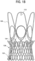
- FIG. 1B shows one embodiment of a self expanding stent 100.
- FIG. 1B shows the placement of a double polyester (PET) fabric skirt (dashed line representing inner PET fabric skirt 122 and outer PET fabric skirt 126) relative to a stent component, as well as placement of a valve-component within the stent (e.g., aortic biologic valve prosthesis, dashed line 124), according to some embodiments of the present disclosure.
- An inner skirt covers at least a portion -- for example, either a minor portion (e.g., less than about 20% coverage), a substantial portion (e.g., about 50-90% coverage), or all (e.g., 90%+) of the stent) of the outer surface of the replacement valve.
- the skirt may be sutured to at least the inflow tract of the valve and to the inner surface of the stent, and may serve as a sealing member between the stent and the valve.
- the topology of the inner surface of this fabric is configured to improve blood flow.
- An outer skirt may also be sutured onto the outer surface of the stent (dashed line 126) and may serve as a sealing member between the stent and, for example, a native valve leaflets/cardiac valve (e.g., aortic) annulus/inflow and/or outflow tract.
- the topology of the outer surface of this fabric is configured to improve endothelialisation, for example.
- the skirt may be made using any know material used for such purposes.
- the skirt is comprised of a polyester material, such as a single ply polyester material.
- the preferred polyester is polyethylene terephthalate (PET).
- a double PET fabric skirt may be provided in which the free edge of the stent is covered to avoid injuries of the left ventricle wall and mitral valve (see eg, Fig.12 ).
- FIG. 2A shows an unrolled, flat depiction of another embodiment of a stent component according to some embodiments of the present disclosure.
- This stent component may be the same or similar to the stent component of FIG. 1 , and include the same numbering scheme as set out for Fig. 1 , except that the corresponding reference numeral starts with a "2" instead of a "1".
- the stent component illustrated in FIG. 2A includes some additional features, mainly one or more additional reinforcements 214 for stent section 206, as well as one or more attachment elements 216 in stent section 202. This numbering scheme is generally used throughout the specification.
- Additional reinforcements 214 may comprise arches, which may be inverted as compared to the commissural arches currently provided in stent section 206.
- Attachment elements 216 may be used to removable attach the stent component to a delivery device (e.g., a catheter based system). In some embodiments, elements 216 may serve to hold the stent-valve onto the delivery system until full release of the stent during delivery/implantation, thus allowing for, in some embodiments, the recapture of the stent upon partial release. See FIG. 16-18 .
- the attachment elements 216 may also prevent the stent from "jumping out" of the delivery system just prior to its full release - such jumping out may result in inaccurate positioning of the replacement valve.
- a radiopaque marker 212 may be positioned on or close to an end (e.g., the distal end) of at least one of the arches. A function of such a radiopaque marker is described below in connection with FIGS. 15A-D .
- FIG. 2B show another design of the devices of the current embodiments.
- the stent component illustrated in FIG. 2A-B includes some additional features, mainly one or more additional reinforcements 214 for stent section 206, as well as one or more attachment elements 216 in stent section 202.
- Such attachment elements may be formed generally in the shape of a bent, or curved angled member (e.g., an "L” or "J” like shape). In some embodiments, such attachment elements may be a hook (e.g., a "J” like shape).
- Some embodiments of the present disclosure include, for example stents and valved-stents: for anchoring towards the ascending aorta; for anchoring towards the left ventricle; for valve fixation; and/or for valved-stent stabilization, as well as other possible applications.
- Figures 3A-B and 4 show examples of stent designs based on such embodiments.
- FIG. 3A and 3B show a stent design with longitudinal elements for commissural valve fixation.
- Figure 3B shows an unrolled, flat depiction of the above stent design.
- These figures show the stabilization arch 308 (conically shaped section), reinforcement crown 306 (cylindrical section), longitudinal valve fixation elements 320 (cylindrical section), forward anchoring crown 304 (e.g., towards LV or otherwise preventing movement of device in a direction opposite of blood flow) (conically shaped section), and reverse anchoring crown 302 (e.g., towards ascending aorta or otherwise preventing movement of device in the direction of blood flow) (conically shaped section).
- FIG. 4 shows the stabilization arch 408 (conically shaped section), longitudinal valve fixation elements 420 (cylindrical section), forward anchoring crown 404 (e.g., towards LV or otherwise preventing movement of device in the direction of blood flow) (conically shaped section), and reverse anchoring crown 402 (e.g., towards ascending aorta or otherwise preventing movement of device in a direction opposite of blood flow) (conically shaped section).
- the reverse anchoring crown 402 may be comprised of two rows (plurality) of meanders for improved stability.
- the fixation elements 420 together help to form the cylindrical shape of the optional third section of the stent. That is, the fixation elements 420 are preferably curved around the longitudinal axis of the stent and, in some embodiments, may form the circumference of the third section of the stent.
- a stent which includes a section for commissural valve fixation which is composed of a plurality (e.g., two, three, four, five, six, eight, etc.) longitudinal elements connected on one side to a conically shaped section (for example) used for anchoring towards the left ventricle and on the other side to the conically shaped section (for example) used for stabilization.
- a section for commissural valve fixation which is composed of a plurality (e.g., two, three, four, five, six, eight, etc.) longitudinal elements connected on one side to a conically shaped section (for example) used for anchoring towards the left ventricle and on the other side to the conically shaped section (for example) used for stabilization.
- the stent is designed to better match the size and shape of a biological valve with narrow commissural posts and, in some embodiments, allow a more robust suturing of the valve commissural posts to the stent.
- Narrow commissural posts according to some embodiments improve the perfusion of the coronary arteries via the sinus of vasalva.
- an additional reinforcement crown may be added as well in some embodiments.
- the stent design allowing for the fixation of the valve commissural posts provides a further advantage, as the size and shape of such stents preferably does not change substantially, and even more preferably, does not change during a required crimping process for loading the stent (with valve, "valved-stent") onto a delivery catheter. Accordingly, this may reduce (and preferably does reduce) the risks of suture damage and facilitating crimping and subsequently releasing of the valved-stent (for example).
- FIG. 5 is provided to illustrate the dimensions of the first and second sections of the stent component.
- D3 represents the diameter of the most proximal edge of the stent component in the expanded configuration.
- D2 represents the diameter of the stent component at the juncture between the first conical section 502 and second conical section 504 of the stent component.
- H2 represents the axial distance between the planes of the diameters D2 and D3 in the expanded configuration, or the length of the first conical section in the expanded configuration.
- Dl represents the diameter of the most distal edge of the second conical section of the stent component in the expanded configuration.
- Hl represents the axial distance between the planes of the diameters Dl and D2 in the expanded configuration, or the length of the second conical section in the expanded configuration.
- the length of the first conical section H2 is between about 3 to about 15 mm (e.g., about 3 mm, about 4 mm, about 5 mm, about 6 mm, about 7 mm, about 8 mm, about 9 mm, about 10 mm, about 11 mm, about 12 mm, about 13 mm, about 14 mm, and about 15 mm).
- the length of the first conical section H2 may been adjusted depending on the intended application of the stent of stent-valve.
- the length of the first conical section H2 may range from about 3 to about 5 mm, about 3 to about 7 mm, about 3 to about 12 mm, about 3 to about 15 mm, about 3 to about 20 mm, about 5 to about 10 mm, about 5 to about 12 mm, about 5 to about 15 mm, about 7 to about 10 mm, about 7 to about 12 mm, about 7 to about 15 mm, about 10 to about 13 mm, about 10 to about 15 mm, or about 7 to about 20 mm.
- the length of this section may be on the smaller end of the scale to avoid potential conflict with a cardiac valve, such as the mitral valve.
- the diameter of the first conical section at D3 is preferably between about 22 mm to about 40 mm (e.g., about 22 mm, about 23 mm, about 24 mm, about 25 mm, about 26 mm, about 27 mm, about 28 mm, about 29 mm, about 30 mm, about 31 mm, about 32 mm, about 33 mm, about 34 mm, about 35 mm, about 36 mm, about 37 mm, about 38 mm, about 39 mm, and about 40 mm).
- This diameter of the first conical section D3 may been adjusted depending on the intended application of the stent of stent-valve.
- the diameter of the first conical section in the expanded configuration D3 may be from between about 15 mm to about 50 mm, from between about 15 mm to about 40 mm, from between about 20 mm to about 40 mm, from between about 24 mm to about 40 mm, from between about 26 mm to about 40 mm, from between about 28 mm to about 40 mm, from between about 30 mm to about 40 mm, from between about 32 mm to about 40 mm, from between about 34 mm to about 40 mm, from between about 36 mm to about 40 mm, from between about 38 mm to about 40 mm, from between about 22 mm to about 38 mm, from between about 22 mm to about 36 mm, from between about 22 mm to about 34 mm, from between about 22 mm to about 32 mm, from between about 22 mm to about 30 mm, from between about 22 mm to about 28 mm, from between about 24 mm to about 34 mm, from between about 25 mm to about 35 mm, or from between about 25 mm to about
- the diameter of the stent component D2 at the juncture of the first and second conical sections D2 is preferably between about 20 mm to about 30 mm (eg., about 20 mm, about 21 mm, about 22 mm, about 23 mm, about 24 mm, about 25 mm, about 26 mm, about 27 mm, about 28 mm, about 29 mm, and about 30 mm).
- This diameter of the stent component D2 may been adjusted depending on the intended application of the stent of stent-valve. For example, this diameter of the stent component D2 may be sized according to the shape of the annulus of the cardiac valve.
- the diameter of the stent component D2 may be from between about 15 mm to about 40 mm, from between about 15 mm to about 30 mm, from between about 18 mm to about 35 mm, from between about 22 mm to about 30 mm, from between about 24 mm to about 30 mm, from between about 26 mm to about 30 mm, from between about 28 mm to about 30 mm, from between about 22 mm to about 28 mm, from between about 22 mm to about 26 mm, from between about 20 mm to about 24 mm, from between about 20 mm to about 26 mm, from between about 20 mm to about 28 mm, and from between about 22 mm to about 32 mm.
- the diameter of the second conical section at Dl is preferably between about 22 mm to about 40 mm (e.g., about 22 mm, about 23 mm, about 24 mm, about 25 mm, about 26 mm, about 27 mm, about 28 mm, about 29 mm, about 30 mm, about 31 mm, about 32 mm, about 33 mm, 34 mm, 35 mm, 36 mm, 37 mm, about 38 mm, about 39 mm, and about 40 mm).
- This diameter of the second conical section Dl may been adjusted depending on the intended application of the stent of stent- valve.
- the diameter of the first conical section in the expanded configuration Dl may be from between about 15 mm to about 50 mm, from between about 15 mm to about 40 mm, from between about 20 mm to about 40 mm, from between about 24 mm to about 40 mm, from between about 26 mm to about 40 mm, from between about 28 mm to about 40 mm, from between about 30 mm to about 40 mm, from between about 32 mm to about 40 mm, from between about 34 mm to about 40 mm, from between about 36 mm to about 40 mm, from between about 38 mm to about 40 mm, from between about 22 mm to about 38 mm, from between about 22 mm to about 36 mm, from between about 22 mm to about 34 mm, from between about 22 mm to about 32 mm, from between about 22 mm to about 30 mm, from between about 22 mm to about 28 mm, from between about 24 mm to about 34 mm, from between about 25 mm to about 35 mm, or from between about 25 mm to about
- the length of the second conical section Hl is between about 3 to about 10 mm (e.g., about 3 mm, about 4 mm, about 5 mm, about 6 mm, about 7 mm, about 8 mm, about 9 mm, and about 10 mm).
- the length of the first conical section Hl may been adjusted depending on the intended application of the stent of stent-valve.
- the length of the first conical section H2 may range from about 3 to about 5 mm, about 3 to about 15 mm, about 3 to about 20 mm, about 5 to about 10 mm, about 7 to about 10 mm, about 7 to about 12 mm, about 7 to about 15 mm, about 10 to about 13 mm, about 5 to about 15 mm, about 7 to about 20 mm.
- the length of this section may be on the smaller end of the scale to avoid potential conflict with a cardiac valve, such as the mitral valve.
- FIG. 6 is provided to illustrate the dimensions of the first and second sections of the stent component, and particularly the angles of the anchoring crowns that help to define these conical sections.
- the ⁇ l angle defines the angle of the anchoring crown of the second conical section of the stent component in the expanded configuration.
- the ⁇ 2 angle defines the angle of the anchoring crown of the first conical section of the stent component in the expanded configuration.
- the ⁇ 3 angle defines the angle of bending of the tip, which is done so as to prevent injuries of sinus (see also, FIG. 10 ).
- the ⁇ l angle is preferably between from about 10 degree to about 80 degree (e.g., about 10 degree, about 15 degree, about 20 degree, about 25 degree, about 30 degree, about 35 degree, about 40 degree, about 45 degree, about 50 degree, about 55 degree, about 60 degree, about 65 degree, about 70 degree, about 75 degree, and about 80 degree), more preferably between from about 20 degree to about 70 degree, most preferable between from about 30 degree to about 60 degree.
- about 10 degree to about 80 degree e.g., about 10 degree, about 15 degree, about 20 degree, about 25 degree, about 30 degree, about 35 degree, about 40 degree, about 45 degree, about 50 degree, about 55 degree, about 60 degree, about 65 degree, about 70 degree, about 75 degree, and about 80 degree
- about 20 degree to about 70 degree most preferable between from about 30 degree to about 60 degree.
- the ⁇ l angle is between from about 20 degree to about 80 degree, between from about 20 degree to about 60 degree, between from about 20 degree to about 50 degree, between from about 20 degree to about 45 degree, between from about 40 degree to about 60 degree, between from about 45 degree to about 60 degree, between from about 30 degree to about 50 degree, between from about 30 degree to about 45 degree, between from about 30 degree to about 40 degree, or between from about 25 degree to about 45 degree.
- the ⁇ 2 angle is preferably between from about 5 degree to about 50 degree (e.g., about 5 degree, about 10 degree, about 15 degree, about 20 degree, about 25 degree, about 30 degree, about 35 degree, about 40 degree, about 45 degree, and about 50 degree), more preferably between from about 10 degree to about 40 degree, most preferable between from about 10 degree to about 30 degree.
- the ⁇ 2 angle is between from about 5 degree to about 45 degree, between from about 5 degree to about 40 degree, between from about 5 degree to about 30 degree, between from about 5 degree to about 25 degree, between from about 5 degree to about 20 degree, between from about 5 degree to about 15 degree, between from about 10 degree to about 20 degree, between from about 10 degree to about 25 degree, between from about 10 degree to about 30 degree, between from about 10 degree to about 40 degree, between from about 10 degree to about 45 degree, between from about 15 degree to about 40 degree, between from about 15 degree to about 30 degree, between from about 15 degree to about 25 degree, between from about 20 degree to about 45 degree, between from about 20 degree to about 40 degree, or between from about 20 degree to about 30 degree
- the ⁇ 3 angle is preferably between from about 0 degree to about 180 degree (e.g., about 5 degree, about 10 degree, about 15 degree, about 20 degree, about 25 degree, about 30 degree, about 35 degree, about 40 degree, about 45 degree, about 50 degree, about 55 degree, about 60 degree, about 65 degree, about 70 degree, about 75 degree, about 80 degree, about 85 degree, about 90 degree, about 95 degree, about 100 degree, about 105 degree, about 110 degree, about 115 degree, about 120 degree, about 125 degree, about 130 degree, about 135 degree, about 140 degree, about 145 degree, about 150 degree, about 155 degree, about 160 degree, about 165 degree, about 170 degree, about 175 degree, and about 180 degree).
- the ⁇ 3 angle is between from about 45 degree to about 90 degree, between from about 45 degree to about 180 degree, between from about 60 degree to about 90 degree, between from about 45 degree to about 120 degree, between from about 60 degree to about 120 degree, between from about 90 degree to about 120 degree, between from about 90 degree to about 180 degree, or between from about 120 degree to about 180 degree.
- FIG. 7 shows the size and shape of stabilization arches for the stent component in the expanded configuration according to some embodiments of the disclosure.
- the ⁇ 4 and ⁇ 5 angles represent the offset angle from a longitudinal axis of the stabilization arches of the forth section of the stent in the expanded configuration. If the stabilization arches are directed away from the center of the stent, the ⁇ 4 angle is used. If the stabilization arches are directed toward from the center of the stent, the ⁇ 5 angle is used.
- the ⁇ 4 angle is preferably between from about 0 degree to about 60 degree (e.g., about 5 degree, about 10 degree, about 15 degree, about 20 degree, about 25 degree, about 30 degree, about 35 degree, about 40 degree, about 45 degree, about 50 degree, about 55 degree, and about 60 degree). According to some embodiments, the ⁇ 4 angle is between from about 20 degree to about 60 degree, between from about 30 degree to about 60 degree, between from about 40 degree to about 60 degree, between from about 45 degree to about 60 degree, between from about 30 degree to about 50 degree, between from about 30 degree to about 45 degree, between from about 20 degree to about 40 degree, or between from about 15 degree to about 45 degree.
- the ⁇ 5 angle is preferably between from about 0 degree to about 20 degree (e.g., about 5 degree, about 10 degree, about 15 degree, and about 20 degree). According to some embodiments, the ⁇ 5 angle is between from about 5 degree to about 20 degree, between from about 10 degree to about 20 degree, between from about 15 degree to about 20 degree, between from about 0 degree to about 15 degree, between from about 0 degree to about 10 degree, between from about 5 degree to about 15 degree, between from about 10 degree to about 15 degree, or between from about 10 degree to about 20 degree.
- FIG. 7 also shows the length of the first section of the stent component H2, the length of the combined second section and optional third section of the stent component H3, and the length of the forth section of the stent component Hl. H2 is as described above.
- the length of the combined second section and optional third section of the stent component H3 is between about 3 to about 50 mm (e.g., about 3 mm, about 4 mm, about 5 mm, about 6 mm, about 7 mm, about 8 mm, about 9 mm, about 10 mm, about 11 mm, about 12 mm, about 13 mm, about 14 mm, about 15 mm, about 20 mm, about 22 mm, about 24 mm, about 25 mm, about 26 mm, about 28 mm, about 30 mm, about 32 mm, about 34 mm, about 36 mm, about 38 mm, about 40 mm, about 42 mm, about 44 mm, about 45 mm, about 46 mm, about 48 mm, and about 50 mm).
- about 3 to about 50 mm e.g., about 3 mm, about 4 mm, about 5 mm, about 6 mm, about 7 mm, about 8 mm, about 9 mm, about 10 mm, about 11 mm, about 12 mm
- the length of the first conical section H3 may been adjusted depending on the intended application of the stent of stent-valve.
- the length of the first conical section H3 may range from about 3 to about 40 mm, about 3 to about 30 mm, about 3 to about 20 mm, about 3 to about 10 mm, about 10 to about 50 mm, about 10 to about 40 mm, about 10 to about 30 mm, about 10 to about 20 mm, about 15 to about 50 mm, about 15 to about 40 mm, about 15 to about 30 mm, about 20 to about 50 mm, about 20 to about 40 mm, about 20 to about 30 mm, about 15 to about 50 mm, about 25 to about 50 mm, about 30 to about 50 mm, about 40 to about 50 mm, about 15 to about 40 mm, about 25 to about 40 mm, or about 30 to about 40 mm.
- the third section of the stent component is not used.
- H3 would be the same as Hl, described above
- the length of the forth section and of the stent component H4 is between about 5 to about 50 mm (e.g., about 5 mm, about 6 mm, about 7 mm, about 8 mm, about 9 mm, about 10 mm, about 11 mm, about 12 mm, about 13 mm, about 14 mm, about 15 mm, about 20 mm, about 22 mm, about 24 mm, about 25 mm, about 26 mm, about 28 mm, about 30 mm, about 32 mm, about 34 mm, about 36 mm, about 38 mm, about 40 mm, about 42 mm, about 44 mm, about 45 mm, about 46 mm, about 48 mm, and about 50 mm).
- the length of the first conical section H4 may been adjusted depending on the intended application of the stent of stent-valve.
- the length of the first conical section H4 may range from about 5 to about 40 mm, about 5 to about 30 mm, about 5 to about 20 mm, about 5 to about 10 mm, about 10 to about 50 mm, about 10 to about 40 mm, about 10 to about 30 mm, about 10 to about 20 mm, about 15 to about 50 mm, about 15 to about 40 mm, about 15 to about 30 mm, about 20 to about 50 mm, about 20 to about 40 mm, about 20 to about 30 mm, about 15 to about 50 mm, about 25 to about 50 mm, about 30 to about 50 mm, about 40 to about 50 mm, about 15 to about 40 mm, about 25 to about 40 mm, or about 30 to about 40 mm.
- the stent components of the stent-valves may be classified into different categories of sizes, such as small, medium, and large.
- the stent components may be sized as small, medium, and large according the following table.
- FIG. 8 shows a mating coupling between the attachment elements 316 of the stent and a stent-holder of a delivery device, according to some embodiments of the present disclosure.
- the attachment elements may include a crochet-like configuration that engages, for example, a groove or other opening within the stent holder.
- Such attachment elements may be formed generally in the shape of a bent, or curved angled member (e.g., an "L" or "J” like shape).
- such attachment elements may be a hook (e.g., a "J” like shape).
- the attachment element may be provided in an angled shape, for example, that extends from the body of the stent inwardly toward a central, longitudinal axis of the stent.
- the opening in the stent holder e.g., groove
- the opening in the stent holder may allow for a safe release of the stent upon rotation of the delivery system (e.g., a portion, all or members thereof - e.g., rotation of the stent holder).
- the end of the attachment element slides onto the surface "S" and is thereby forced, according to some embodiments, to disengage the stent holder when reaching the edge "E".
- multiple fixation elements e.g., 2 or more, 3 or more, 4 or more, 5 or more, 6 or more, 7 or more, 8 or more, 9 or more, 10 or more, 11 or more, 12 or more, 13 or more, 14 or more, 15 or more, 16 or more, 17 or more, 18 or more, 19 or more, 20 or more, etc. or 2 to 5, 2 to 10, 2 to 20, 2 to 30, 2 to 40, etc.
- a matching/complimentary element e.g., stent holder with pins
- the design of the multiple fixation elements may allow for the fixation of the stent onto the catheter only when the stent is crimped (see e.g., FIG. 9 ).
- the fixation may release automatically when the stent starts to expand. That is, the shape of the stent in the unexpanded state is designed to have holes or free areas that can be used to couple the stent with a stent holder. When the stent is expanded, the expanded configuration is absent such holes or free spaces and thus the stent automatically becomes uncoupled or releases from the stent holder upon expansion.
- the design of the stent component allows for self-positioning of the replacement valve under diastolic pressure. Once delivered slightly above the aortic annulus, the stent-valve migrates toward the left ventricle due to the forces caused by the diastolic pressure until it reaches a stable position given by the shape / radial force of the anchoring crown (conically shaped section 2) and the compliance of the aortic annulus ( FIG. 13 ).
- the stent-valve may be released such that at least a portion of section 102 of the stent component is released at the native valve annulus (e.g., release position).
- the release of the stent valve in the release position preferably comprises a full release of the stent valve (i.e., the stent-valve is fully released from the delivery system). Accordingly, subsequent beating of the heart after release results in the stent-valve sliding into a final position, which preferably is the groove formed between stent component sections 102 and 104.
- the distance between the release position and the final position may comprise a predetermined range, which may include: between about 3 mm and about 20 mm, between about 7 mm to about 11 mm, between about 8 mm to about 12 mm, and between about 9 mm to about 13 mm.
- the stent-valve may be released (which according to some embodiments, is a full release from the stent-valve delivery system) such that at least a portion of section 104 of the stent component is released at the native valve annulus (e.g., release position), and subsequent beating of the heart after release results in the stent-valve sliding into a final position which preferably is the groove portion (as indicated above) between sections 104 and 102.
- a range of distances between release locations and final positions which may be in reference to either locations at the implantation site (e.g., within the lumen/heart) and/or locations on the stent component, may be between about 4 mm and 8 mm.
- a valved-sent delivery system, and method for delivering the valved-stent to an implantation site are provided in which the valved-sent is expanded at the implantation site in a stepwise manner (for example) from its distal end towards its proximal end.
- a release procedure for causing expansion of a valved-stent may involve pulling back a sheath element on a catheter delivery device.
- the sheath element constrains the valved-sent toward a section of the heart (for example, the left ventricle of the heart). According to such a procedure, there may be no interaction of the delivery system with the anatomy of the ascending aorta/aortic arch.
- the sheath constraining the valved-stent, and the tip of the delivery system may not be required to enter the aortic arch during the release procedure, which is beneficial since such entry potentially can cause a bending moment acting onto the valved- stent and result in inaccurate positioning of the valved-stent (e.g., tilting).
- a cardiac stent-valve delivery system that includes an inner assembly and an outer assembly.
- the inner assembly may include a guide wire lumen (e.g., polymeric tubing) and a stent holder for removable attachment to a stent-valve.
- the outer assembly may include a sheath.
- the inner member and the outer member may be co-axially positioned and slidable relative to one another in order to transition from a closed position to an open position, such that in the closed position the sheath encompasses the stent-valve still attached to the stent holder and thus constrains expansion of the stent-valve. In the open position, the outer sheath may not constrain expansion of the stent-valve and thus the stent-valve may detach from the stent holder and expand to a fully expanded configuration.
- the inner assembly of the delivery device may include a fluoroscopic marker fixed to the guide wire lumen distal of the stent holder.
- the diameter of the outer assembly of the delivery device varies over its longitudinal axis.
- the delivery system comprises a rigid (e.g., stainless steel) shaft in communication with a proximal end of the guide wire lumen.
- the delivery system comprises a luer connector in communication with the rigid shaft.
- FIG. 14A shows a delivery system 550 for distal-to-proximal expansion of a stent-valve (i.e., section 108 to section 102 - see Fig. 1 ), according to some embodiments of the present disclosure.
- the system 550 may include an inner member 552 and an outer member 554 (e.g., sheath) which are co-axially positioned and slidable one against the other.
- the inner member 552 may comprise tubing 568 (e.g., polymeric tubing) which serves as a guide wire lumen and on which at least one of (and preferably several or all) a tip 556, a fluoroscopic marker 558, and a stent-holder 560 are affixed (e.g., bonded).
- the polymeric tubing may be reinforced proximally with a rigid (e.g., stainless steel) shaft.
- a luer connector 562 affixed to a stainless steel shaft 564 to allow flushing of the guide wire lumen with saline (for example).
- the outer member 554 may comprise a distally arranged sheath which may be used to constrain the stent in a closed/contracted (e.g., substantially non-expanded) configuration. Proximally, the sheath may be fixed to a hemostasis valve 566 to allow the flushing of the annular space between the inner and outer members with saline (for example).
- the diameter of the outer member may vary over its longitudinal direction (e.g., smaller diameter proximally to decrease the bending stiffness of the delivery system).
- the deployment of the stent-valve may occur by holding the inner member at the level of the stainless steel shaft with one hand and the outer member at the level of the hemostasis valve with the other hand. Then, upon positioning of the replacement valve (e.g., under fluoroscopic control), the outer member is pulled back with the inner member being kept at its original position, until the stent is fully deployed.
- FIG. 14B shows the size and shape of delivery system according to some embodiments.
- Ds refers to the stent sleeve diameters, which are the inner and outer sleeve diameters.
- the inner diameter of the stent sleeve is preferably from between about 4 to about 14 mm (eg., about 4 mm, 5 mm, 6 mm, 7 mm, 8 mm, 9 mm, 10 mm, 11 mm, 12 mm, 13 mm, or 14 mm).
- the outer diameter of the stent sleeve is preferably from between about 5 to about 15 mm (e.g., about 5 mm, 6 mm, 7 mm, 8 mm, 9 mm, 10 mm, 11 mm, 12 mm, 13 mm, 14 mm, or 15 mm).
- Ls refers to the stent sleeve length.
- the stent sleeve length is preferably from between about 20 mm to about 120 mm (eg, about 20 mm, 25 mm, 30 mm, 35 mm, 40 mm, 50 mm, 60 mm, 70 mm, 80 mm, 90 mm, 100 mm, 110 mm, or 120 mm).
- the stent sleeve length is between from about 20 mm to about 100 mm, about 20 mm to about 80 mm, about 20 mm to about 60 mm, about 20 mm to about 40 mm, about 40 mm to about 120 mm, about 60 mm to about 120 mm, about 80 mm to about 120 mm, about 100 mm to about 120 mm, about 40 mm to about 100 mm, or about 60 mm to about 100 mm.
- Lu refers to the usable length.
- the usable length is preferably from between about 150 mm to about 500 mm (e.g., about 150 mm, 175 mm, 200 mm, 225 mm, 250 mm, 300 mm, 350 mm, 400 mm, 450 mm, or 500 mm).
- the usable length is between from about 150 mm to about 450 mm, about 150 mm to about 400 mm, about 150 mm to about 350 mm, about 150 mm to about 300 mm, about 150 mm to about 250 mm, about 200 mm to about 500 mm, about 300 mm to about 500 mm, about 350 mm to about 500 mm, about 400 mm to about 500 mm, about 200 mm to about 400 mm, or about 300 mm to about 400 mm.
- Lt refers to the total length.
- the total length is preferably from between about 200 mm to about 1000 mm (e.g., about 200 mm, 225 mm, 250 mm, 300 mm, 350 mm, 400 mm, 450 mm, 500 mm, 550 mm, 600 mm, 650 mm, 700 mm, 750 mm, 800 mm, 850 mm, 900 mm, 950 mm, or 1000 mm).
- the total length is between from about 200 mm to about 900 mm, about 200 mm to about 800 mm, about 200 mm to about 700 mm, about 200 mm to about 600 mm, about 200 mm to about 500 mm, about 200 mm to about 400 mm, about 200 mm to about 300 mm, about 300 mm to about 1000 mm, about 400 mm to about 1000 mm, about 500 mm to about 1000 mm, about 600 mm to about 1000 mm, about 700 mm to about 1000 mm, about 800 mm to about 1000 mm, about 900 mm to about 1000 mm, or about 300 mm to about 800 mm.
- FIGS. 15A-D illustrate an exemplary embodiment of a method of implanting a stent- valve within a human heart according to some embodiments of the present disclosure (e.g., an aortic valve replacement).
- FIG. 15A shows the initial, partial release of the stent 1500, in which the radiopaque 1512 marker positioned on one of the arches of stent section 1508 (see FIG. 1 ), for example, is released distally from the outer sheath.
- the delivery system 1550 may then be rotated as necessary in order to orient the stent 1500 appropriately with respect to, for example, the coronary arteries (e.g., orienting the stent-valve such that the commissures do not face the coronary arteries). More specifically, prior to full release of the stent 1500, the delivery system 1550 may be rotated in order to cause the radiopaque marker 1512 to be placed between the osteum of the left and right coronary arteries.
- FIG. 15B shows a further, but still partial release of the stent 1500, in which the larger, orientation arches 1509 of stent section 1508 are released from the outer sheath 1554 and placed into contact with the aorta (for example).
- FIG. 15C illustrates an example of yet a further, still partial release but almost fully released, illustration of the stent release, in which the first conical crown of stent section 1504 is released from the outer sheath 1554 for engagement with the native valve leaflets 1580.
- FIG. 15D illustrates an example of a full release of the stent, in which the second conical crown of stent section 1502 (i.e., the proximal section of the stent; see Fig. 1 ) is released from the outer sheath 1554 for engagement with the annulus/inflow tract.
- the second conical crown of stent section 1502 i.e., the proximal section of the stent; see Fig. 1
- the outer sheath 1554 for engagement with the annulus/inflow tract.
- cardiac stent-valves are provided as cardiac replacement valves.
- On the left (systemic) side of the heart are: 1) the mitral valve, located between the left atrium and the left ventricle, and 2) the aortic valve, located between the left ventricle and the aorta. These two valves direct oxygenated blood coming from the lungs through the left side of the heart into the aorta for distribution to the body.
- the tricuspid valve located between the right atrium and the right ventricle
- the pulmonary valve located between the right ventricle and the pulmonary artery.
- Heart valves consist of stenosis, in which a valve does not open properly, and/or insufficiency, also called regurgitation, in which a valve does not close properly.
- insufficiency also called regurgitation
- heart valves may need to be surgically repaired or replaced due to certain types of bacterial or fungal infections in which the valve may continue to function normally, but nevertheless harbors an overgrowth of bacteria on the leaflets of the valve that may embolize and lodge downstream in a vital artery. In such cases, surgical replacement of either the mitral or aortic valve (left-sided heart valves) may be necessary.
- bacterial or fungal growth on the tricuspid valve may embolize to the lungs resulting in a lung abscess. In such cases replacement of the tricuspid valve even though no tricuspid valve stenosis or insufficiency is present.
- a method for replacing a worn or diseased valve comprising transapically implanting a replacement valve, wherein the replacement valve is a stent-valve of the present disclosure.
- the replacement valve comprises a valve component and a stent component, wherein the valve component is connect to the stent component.
- the stent component preferably comprises a longitudinal axis and preferably has four sections.
- the first section includes a substantially conical shape having a narrow end, a broad end and a predetermined first height.
- the second section includes a substantially conical shape having a narrow end, a broad end and a predetermined second height.
- the center of each of the first section and the second section are preferably arranged to align substantially with the longitudinal axis.
- the narrow ends of the first section and second section are preferably arranged to meet forming an annular groove to receive the annulus of worn or diseased cardiac valve at an implantation site of the heart.
- the first height of the first section is preferably greater than the second height of the second section.
- the placement of the stent- valve may be upstream of the annulus, whereupon when the stent-valve will be locked into position once the annular groove of the stent component receives the annulus.
- methods for implanting a replacement valve into a heart of a mammal comprising delivering a replacement valve to an implantation site of the heart of the mammal.
- the implantation site preferably comprises a release location and a final location; and the release location is spaced apart from the final location (and according to some embodiments, the spacing comprises a predetermined distance), and in some embodiments, in a blood upflow direction. Releasing the replacement valve at the release location, the replacement valve is able to slide into the final location, generally upon at least one beat of the heart subsequent to the replacement valve being released at the release location.
- the methods provide that when the replacement valve sliding into the final location, the replacement valve is substantially positioned to the final location.
- a method for replacing an aortic valve within a human body.
- a stent-valve may be covered with a sheath in order to maintain the stent-valve in a collapsed configuration.
- the stent-valve may then may be inserted in the collapsed configuration into the human body without contacting the ascending aorta or aortic arch.
- the stent-valve may be partially expanded by sliding the sheath towards the left ventricle of the heart. This sliding of the sheath towards the left ventricle may cause expansion of a distal end of the stent-valve while the proximal end of the stent-valve remains constrained by the sheath.
- the sheath may be further slid towards the left ventricle of the heart in order to cause full expansion of the stent-valve.
- the stent-valve may be recaptured prior to its full expansion by sliding the sheath in the opposite direction.
- a method for cardiac valve replacement includes releasing a distal end of a stent-valve from a sheath, where the distal end includes a radiopaque marker positioned thereon.
- the stent-valve is rotated, if necessary, to orient the stent-valve appropriately with respect to the coronary arteries (e.g., to prevent the commissures from facing the coronary arteries).
- Arches of the stent-valve are released from the sheath, in order to cause the arches to contact the aorta.
- a first conical crown of the stent-valve is released from the sheath, in order to cause the first conical crown to contact the native valve leaflets.
- a second crown of the stent-valve is released from the sheath, in order to cause the second crown to contact an annulus/inflow tract.
- the second crown may be the proximal section of the stent-valve such that releasing the second crown causes the stent-valve to be fully released from the sheath.
- a replacement valve for use within a human body where the replacement valve includes a valve component and a stent component.
- the stent component also may be used without a connected valve as a stent.
- the stent devices of the present disclosure may use used to mechanically widen a narrowed or totally obstructed blood vessel; typically as a result of atherosclerosis. Accordingly, the stent devices of the present disclosure may use used is angioplasty procedures.
- PCI percutaneous coronary intervention
- coronary angioplasty to treat the stenotic (narrowed) coronary arteries of the heart found in coronary heart disease
- peripheral angioplasty performed to mechanically widen the opening in blood vessels other than the coronary arteries.
Landscapes
- Health & Medical Sciences (AREA)
- Cardiology (AREA)
- Engineering & Computer Science (AREA)
- Biomedical Technology (AREA)
- Life Sciences & Earth Sciences (AREA)
- Transplantation (AREA)
- Heart & Thoracic Surgery (AREA)
- Vascular Medicine (AREA)
- Oral & Maxillofacial Surgery (AREA)
- Animal Behavior & Ethology (AREA)
- General Health & Medical Sciences (AREA)
- Public Health (AREA)
- Veterinary Medicine (AREA)
- Prostheses (AREA)
- Media Introduction/Drainage Providing Device (AREA)
- Surgical Instruments (AREA)
Claims (11)
- Valve de remplacement destinée à être utilisée dans un corps humain, comprenant :un composant de valve comprenant du tissu de péricarde de mammifère ;un composant d'endoprothèse (100) pour loger le composant de valve, etune jupe intérieure en tissu (122) recouvrant au moins une partie d'une surface extérieure du composant de valve, la jupe intérieure en tissu servant d'élément d'étanchéité entre le composant d'endoprothèse et le composant de valve, la jupe intérieure en tissu (122) recouvrant entre 50 % et 90 % de l'endoprothèse,une jupe extérieure en tissu (126) recouvrant une surface extérieure du composant d'endoprothèse, la jupe extérieure en tissu servant d'élément d'étanchéité entre le composant d'endoprothèse et la valve native, la topologie de la surface intérieure de la jupe intérieure en tissu étant configurée pour améliorer le flux sanguin et la topologie de la surface extérieure de la jupe extérieure en tissu étant configurée pour améliorer l'endothélialisation, la jupe intérieure et la jupe extérieure en tissu (122, 126) formant une double jupe en tissu qui recouvre le bord d'entrée du composant d'endoprothèse (100).
- Valve de remplacement selon la revendication 1, la jupe intérieure en tissu (122) étant suturée au canal d'entrée du composant de valve et à une surface intérieure du composant d'endoprothèse (100).
- Valve de remplacement selon l'une quelconque des revendications précédentes, la jupe extérieure en tissu (126) étant suturée à une surface extérieure du composant d'endoprothèse (100).
- Valve de remplacement selon l'une quelconque des revendications précédentes, au moins l'une des jupes en tissu (122, 126) comprenant un matériau en polyester.
- Valve de remplacement selon la revendication 4, le polyester étant un polyéthylène téréphtalate.
- Valve de remplacement selon l'une quelconque des revendications précédentes, la jupe extérieure en tissu (126) recouvrant une section du composant d'endoprothèse (100) qui est formée et dimensionnée pour s'adapter à l'anneau aortique.
- Valve de remplacement selon l'une quelconque des revendications précédentes, la section d'entrée étant de forme conique.
- Valve de remplacement selon l'une quelconque des revendications précédentes, le composant d'endoprothèse (100) comprenant un corps cylindrique configuré pour loger au moins une partie du composant de valve.
- Valve de remplacement selon l'une quelconque des revendications précédentes, le composant d'endoprothèse (100) étant formé à partir d'un seul tube ou d'une seule feuille de métal.
- Valve de remplacement selon l'une quelconque des revendications précédentes, le composant d'endoprothèse (100) étant auto-expansible.
- Valve de remplacement selon l'une quelconque des revendications 1 à 9, le composant d'endoprothèse (100) étant expansible par ballonnet.
Applications Claiming Priority (5)
| Application Number | Priority Date | Filing Date | Title |
|---|---|---|---|
| US58707P | 2007-10-25 | 2007-10-25 | |
| US6718908P | 2008-02-25 | 2008-02-25 | |
| US5256008P | 2008-05-12 | 2008-05-12 | |
| PCT/EP2008/064558 WO2009053497A1 (fr) | 2007-10-25 | 2008-10-27 | Stents, stents à valve et procédés et systèmes de mise en place de ceux-ci |
| EP08843043.4A EP2205183B1 (fr) | 2007-10-25 | 2008-10-27 | Un systeme pour remplacer une valve cardiaque |
Related Parent Applications (2)
| Application Number | Title | Priority Date | Filing Date |
|---|---|---|---|
| EP08843043.4A Division EP2205183B1 (fr) | 2007-10-25 | 2008-10-27 | Un systeme pour remplacer une valve cardiaque |
| EP08843043.4A Division-Into EP2205183B1 (fr) | 2007-10-25 | 2008-10-27 | Un systeme pour remplacer une valve cardiaque |
Publications (3)
| Publication Number | Publication Date |
|---|---|
| EP3311779A1 EP3311779A1 (fr) | 2018-04-25 |
| EP3311779B1 true EP3311779B1 (fr) | 2024-04-24 |
| EP3311779C0 EP3311779C0 (fr) | 2024-04-24 |
Family
ID=40083683
Family Applications (3)
| Application Number | Title | Priority Date | Filing Date |
|---|---|---|---|
| EP08843043.4A Not-in-force EP2205183B1 (fr) | 2007-10-25 | 2008-10-27 | Un systeme pour remplacer une valve cardiaque |
| EP13185563.7A Active EP2679198B1 (fr) | 2007-10-25 | 2008-10-27 | Stents à valve et systèmes de mise en place de ceux-ci |
| EP17206130.1A Active EP3311779B1 (fr) | 2007-10-25 | 2008-10-27 | Valve cardiaque |
Family Applications Before (2)
| Application Number | Title | Priority Date | Filing Date |
|---|---|---|---|
| EP08843043.4A Not-in-force EP2205183B1 (fr) | 2007-10-25 | 2008-10-27 | Un systeme pour remplacer une valve cardiaque |
| EP13185563.7A Active EP2679198B1 (fr) | 2007-10-25 | 2008-10-27 | Stents à valve et systèmes de mise en place de ceux-ci |
Country Status (6)
| Country | Link |
|---|---|
| US (10) | US8647381B2 (fr) |
| EP (3) | EP2205183B1 (fr) |
| JP (5) | JP5603776B2 (fr) |
| BR (1) | BRPI0819217B8 (fr) |
| CA (1) | CA2703665C (fr) |
| WO (1) | WO2009053497A1 (fr) |
Families Citing this family (373)
| Publication number | Priority date | Publication date | Assignee | Title |
|---|---|---|---|---|
| WO2005074367A2 (fr) | 2004-02-03 | 2005-08-18 | Atria Medical Inc. | Dispositif et procede de controle de la pression in vivo |
| US8091556B2 (en) | 2001-04-20 | 2012-01-10 | V-Wave Ltd. | Methods and apparatus for reducing localized circulatory system pressure |
| CA2769574C (fr) | 2001-10-04 | 2014-12-23 | Neovasc Medical Ltd. | Implant reducteur de flux |
| US6866679B2 (en) | 2002-03-12 | 2005-03-15 | Ev3 Inc. | Everting stent and stent delivery system |
| US9579194B2 (en) | 2003-10-06 | 2017-02-28 | Medtronic ATS Medical, Inc. | Anchoring structure with concave landing zone |
| IL158960A0 (en) | 2003-11-19 | 2004-05-12 | Neovasc Medical Ltd | Vascular implant |
| JP2008513060A (ja) | 2004-09-14 | 2008-05-01 | エドワーズ ライフサイエンシーズ アーゲー | 心臓弁逆流の処置のためのデバイスおよび方法 |
| DE102005003632A1 (de) | 2005-01-20 | 2006-08-17 | Fraunhofer-Gesellschaft zur Förderung der angewandten Forschung e.V. | Katheter für die transvaskuläre Implantation von Herzklappenprothesen |
| US7914569B2 (en) | 2005-05-13 | 2011-03-29 | Medtronics Corevalve Llc | Heart valve prosthesis and methods of manufacture and use |
| AU2006315812B2 (en) | 2005-11-10 | 2013-03-28 | Cardiaq Valve Technologies, Inc. | Balloon-expandable, self-expanding, vascular prosthesis connecting stent |
| US20070213813A1 (en) | 2005-12-22 | 2007-09-13 | Symetis Sa | Stent-valves for valve replacement and associated methods and systems for surgery |
| US9681948B2 (en) | 2006-01-23 | 2017-06-20 | V-Wave Ltd. | Heart anchor device |
| WO2008013915A2 (fr) * | 2006-07-28 | 2008-01-31 | Arshad Quadri | Prothèse à valve percutanée et système et procédé pour implanter une telle prothèse |
| US9585743B2 (en) | 2006-07-31 | 2017-03-07 | Edwards Lifesciences Cardiaq Llc | Surgical implant devices and methods for their manufacture and use |
| US8052750B2 (en) | 2006-09-19 | 2011-11-08 | Medtronic Ventor Technologies Ltd | Valve prosthesis fixation techniques using sandwiching |
| US11304800B2 (en) | 2006-09-19 | 2022-04-19 | Medtronic Ventor Technologies Ltd. | Sinus-engaging valve fixation member |
| US8834564B2 (en) | 2006-09-19 | 2014-09-16 | Medtronic, Inc. | Sinus-engaging valve fixation member |
| WO2009024859A2 (fr) | 2007-08-21 | 2009-02-26 | Symetis Sa | Endoprothèses valvulaires pour un remplacement de valvule et procédés associés et systèmes pour une chirurgie |
| US7896915B2 (en) | 2007-04-13 | 2011-03-01 | Jenavalve Technology, Inc. | Medical device for treating a heart valve insufficiency |
| EP2155114B8 (fr) | 2007-06-04 | 2020-05-20 | St. Jude Medical, LLC | Valvules cardiaques prothétiques |
| CA2978267A1 (fr) | 2007-08-23 | 2009-02-23 | Dfm, Llc | Procedes de traitement de patients pediatriques a l'aide de dexmedetomidine |
| US8425593B2 (en) | 2007-09-26 | 2013-04-23 | St. Jude Medical, Inc. | Collapsible prosthetic heart valves |
| US9532868B2 (en) | 2007-09-28 | 2017-01-03 | St. Jude Medical, Inc. | Collapsible-expandable prosthetic heart valves with structures for clamping native tissue |
| US20090105813A1 (en) * | 2007-10-17 | 2009-04-23 | Sean Chambers | Implantable valve device |
| BRPI0819217B8 (pt) | 2007-10-25 | 2021-06-22 | Symetis Sa | válvula de substituição para uso dentro de um corpo humano, sistema para substituir uma válvula dentro de um corpo humano e sistema de liberação da válvula cardíaca com stent |
| WO2009061389A2 (fr) * | 2007-11-05 | 2009-05-14 | St. Jude Medical, Inc. | Valvules prothétiques cardiaques rétractables/expansibles à montants de stent non extensibles et à caractéristiques de récupération |
| PL2628464T5 (pl) | 2007-12-14 | 2024-10-28 | Edwards Lifesciences Corporation | Zastawka protetyczna |
| US8157853B2 (en) | 2008-01-24 | 2012-04-17 | Medtronic, Inc. | Delivery systems and methods of implantation for prosthetic heart valves |
| WO2011104269A1 (fr) | 2008-02-26 | 2011-09-01 | Jenavalve Technology Inc. | Stent pour le positionnement et l'ancrage d'une prothèse valvulaire dans un site d'implantation dans le cœur d'un patient |
| US9044318B2 (en) | 2008-02-26 | 2015-06-02 | Jenavalve Technology Gmbh | Stent for the positioning and anchoring of a valvular prosthesis |
| DK2257243T3 (da) * | 2008-02-26 | 2014-08-11 | Jenavalve Technology Gmbh | Stent til positionering og forankring af en hjerteklapprotese på et implantationssted i en patients hjerte. |
| US9168130B2 (en) | 2008-02-26 | 2015-10-27 | Jenavalve Technology Gmbh | Stent for the positioning and anchoring of a valvular prosthesis in an implantation site in the heart of a patient |
| US8313525B2 (en) | 2008-03-18 | 2012-11-20 | Medtronic Ventor Technologies, Ltd. | Valve suturing and implantation procedures |
| KR101617052B1 (ko) | 2008-04-23 | 2016-04-29 | 메드트로닉 인코포레이티드 | 스텐트 부착 심장 판막 장치 |
| DK3967274T4 (da) | 2008-04-23 | 2025-08-25 | Medtronic Inc | Hjerteklapanordninger med stent |
| US20090276040A1 (en) | 2008-05-01 | 2009-11-05 | Edwards Lifesciences Corporation | Device and method for replacing mitral valve |
| CA3272239A1 (en) | 2008-06-06 | 2025-10-28 | Edwards Lifesciences Corporation | Low profile transcatheter heart valve |
| AU2009271574B2 (en) | 2008-07-15 | 2015-05-21 | St. Jude Medical, Inc. | Axially anchoring collapsible and re-expandable prosthetic heart valves for various disease states |
| DE202009018984U1 (de) | 2008-07-15 | 2015-01-29 | St. Jude Medical, Inc. | Tasche zur Verwendung in einer Herzklappenprothese |
| AU2009295960A1 (en) * | 2008-09-29 | 2010-04-01 | Cardiaq Valve Technologies, Inc. | Heart valve |
| EP2341871B1 (fr) * | 2008-10-01 | 2017-03-22 | Edwards Lifesciences CardiAQ LLC | Système de mise en place pour implant vasculaire |
| WO2010057262A1 (fr) | 2008-11-21 | 2010-05-27 | Percutaneous Cardiovascular Solutions Pty Limited | Prothèse de valve cardiaque et procédé |
| EP4119098A1 (fr) * | 2009-04-15 | 2023-01-18 | Edwards Lifesciences CardiAQ LLC | Implant vasculaire et système de distribution |
| CA2760461C (fr) | 2009-04-29 | 2014-10-07 | The Cleveland Clinic Foundation | Appareil et procede pour remplacer une valvule cardiaque malade |
| US12453626B2 (en) | 2009-05-04 | 2025-10-28 | V-Wave Ltd. | Shunt for redistributing atrial blood volume |
| US9034034B2 (en) | 2010-12-22 | 2015-05-19 | V-Wave Ltd. | Devices for reducing left atrial pressure, and methods of making and using same |
| US10076403B1 (en) | 2009-05-04 | 2018-09-18 | V-Wave Ltd. | Shunt for redistributing atrial blood volume |
| EP2427143B1 (fr) | 2009-05-04 | 2017-08-02 | V-Wave Ltd. | Dispositif permettant de réguler la pression à l'intérieur d'une cavité cardiaque |
| US12186176B2 (en) | 2009-05-04 | 2025-01-07 | V-Wave Ltd. | Shunt for redistributing atrial blood volume |
| US8075611B2 (en) | 2009-06-02 | 2011-12-13 | Medtronic, Inc. | Stented prosthetic heart valves |
| JP5603934B2 (ja) * | 2009-06-05 | 2014-10-08 | メドトロニック エイティーエス メディカル インコーポレイテッド | 生体補綴弁を取り付けるための可撓性交連構造 |
| US8845722B2 (en) | 2009-08-03 | 2014-09-30 | Shlomo Gabbay | Heart valve prosthesis and method of implantation thereof |
| US9730790B2 (en) | 2009-09-29 | 2017-08-15 | Edwards Lifesciences Cardiaq Llc | Replacement valve and method |
| EP2496181B1 (fr) * | 2009-11-02 | 2017-08-30 | Symetis SA | Bioprothèse aortique et systèmes de mise en place de celle-ci |
| US8449599B2 (en) | 2009-12-04 | 2013-05-28 | Edwards Lifesciences Corporation | Prosthetic valve for replacing mitral valve |
| US8870950B2 (en) | 2009-12-08 | 2014-10-28 | Mitral Tech Ltd. | Rotation-based anchoring of an implant |
| EP4092213B1 (fr) | 2010-01-11 | 2023-12-13 | Välinge Innovation AB | Revêtement de sol avec conception d'interverrouillage |
| US9072603B2 (en) * | 2010-02-24 | 2015-07-07 | Medtronic Ventor Technologies, Ltd. | Mitral prosthesis and methods for implantation |
| US8795354B2 (en) * | 2010-03-05 | 2014-08-05 | Edwards Lifesciences Corporation | Low-profile heart valve and delivery system |
| US20110224785A1 (en) | 2010-03-10 | 2011-09-15 | Hacohen Gil | Prosthetic mitral valve with tissue anchors |
| US8652204B2 (en) | 2010-04-01 | 2014-02-18 | Medtronic, Inc. | Transcatheter valve with torsion spring fixation and related systems and methods |
| US8926692B2 (en) | 2010-04-09 | 2015-01-06 | Medtronic, Inc. | Transcatheter prosthetic heart valve delivery device with partial deployment and release features and methods |
| US8579964B2 (en) | 2010-05-05 | 2013-11-12 | Neovasc Inc. | Transcatheter mitral valve prosthesis |
| US9603708B2 (en) | 2010-05-19 | 2017-03-28 | Dfm, Llc | Low crossing profile delivery catheter for cardiovascular prosthetic implant |
| US10856978B2 (en) | 2010-05-20 | 2020-12-08 | Jenavalve Technology, Inc. | Catheter system |
| WO2011147849A1 (fr) | 2010-05-25 | 2011-12-01 | Jenavalve Technology Inc. | Valvule prothétique et endoprothèse mise en place par cathétérisme comprenant une valvule prothétique et un stent |
| AU2011271007A1 (en) * | 2010-06-21 | 2013-01-31 | Cardiaq Valve Technologies, Inc. | Replacement heart valve |
| CA2804771C (fr) | 2010-07-09 | 2018-02-20 | Highlife Sas | Prothese de valve atrio-ventriculaire transcatheter |
| US11653910B2 (en) | 2010-07-21 | 2023-05-23 | Cardiovalve Ltd. | Helical anchor implantation |
| US9132009B2 (en) | 2010-07-21 | 2015-09-15 | Mitraltech Ltd. | Guide wires with commissural anchors to advance a prosthetic valve |
| US9763657B2 (en) | 2010-07-21 | 2017-09-19 | Mitraltech Ltd. | Techniques for percutaneous mitral valve replacement and sealing |
| US8992604B2 (en) | 2010-07-21 | 2015-03-31 | Mitraltech Ltd. | Techniques for percutaneous mitral valve replacement and sealing |
| ES3023659T3 (en) | 2010-07-23 | 2025-06-02 | Edwards Lifesciences Corp | Retaining mechanisms for prosthetic valves |
| EP2444030A1 (fr) | 2010-08-31 | 2012-04-25 | Biotronik AG | Implant de valvule pour implantation dans un corps animal et/ou le corps humain |
| RU139021U1 (ru) * | 2010-09-10 | 2014-04-10 | Симетис Са | Устройства для замены клапана, системы, содержащие устройство для замены клапана, устройства для замены сердечного клапана и доставляющая система для доставки устройства для замены сердечного клапана |
| AU2015258284B2 (en) * | 2010-09-10 | 2017-09-28 | Symetis Sa | Valve replacement devices, delivery device for a valve replacement device and method of production of a valve replacement device |
| EP2428189A1 (fr) | 2010-09-10 | 2012-03-14 | Symetis Sa | Système de mise en place de cathéter pour valvule d'endoprothèse |
| WO2012040655A2 (fr) | 2010-09-23 | 2012-03-29 | Cardiaq Valve Technologies, Inc. | Valvules prothétiques, dispositifs de pose et procédés afférents |
| ES2601832T3 (es) | 2010-09-24 | 2017-02-16 | Symetis Sa | Válvula-stent y aparato portador |
| EP4309633A3 (fr) | 2010-09-24 | 2024-04-10 | Boston Scientific Medical Device Limited | Système d'implantation de valvule aortique transcathéter |
| US8568475B2 (en) * | 2010-10-05 | 2013-10-29 | Edwards Lifesciences Corporation | Spiraled commissure attachment for prosthetic valve |
| CA3020195C (fr) * | 2010-10-05 | 2020-10-27 | Edwards Lifesciences Corporation | Valve cardiaque prosthetique |
| EP2629699B1 (fr) * | 2010-10-21 | 2017-01-04 | Medtronic, Inc. | Bioprothèse mitrale présentant un profil ventriculaire bas |
| US20120116496A1 (en) * | 2010-11-05 | 2012-05-10 | Chuter Timothy A | Stent structures for use with valve replacements |
| EP2474287A1 (fr) | 2011-01-11 | 2012-07-11 | Symetis Sa | Cathéter de mise en place de valvule d'endoprothèse et sous-ensemble correspondant |
| EP2484309B1 (fr) * | 2011-02-02 | 2019-04-10 | Shlomo Gabbay | Prothèse valvulaire cardiaque |
| US9155619B2 (en) | 2011-02-25 | 2015-10-13 | Edwards Lifesciences Corporation | Prosthetic heart valve delivery apparatus |
| EP4119095A1 (fr) | 2011-03-21 | 2023-01-18 | Cephea Valve Technologies, Inc. | Appareil à soupape basé sur disque |
| US9308087B2 (en) | 2011-04-28 | 2016-04-12 | Neovasc Tiara Inc. | Sequentially deployed transcatheter mitral valve prosthesis |
| US9554897B2 (en) | 2011-04-28 | 2017-01-31 | Neovasc Tiara Inc. | Methods and apparatus for engaging a valve prosthesis with tissue |
| EP2520251A1 (fr) | 2011-05-05 | 2012-11-07 | Symetis SA | Procédé et appareil pour compresser des valvules d'endoprothèse |
| US12502276B2 (en) | 2011-05-16 | 2025-12-23 | Edwards Lifesciences Corporation | Inversion delivery device and method for a prosthesis |
| US11135054B2 (en) | 2011-07-28 | 2021-10-05 | V-Wave Ltd. | Interatrial shunts having biodegradable material, and methods of making and using same |
| US9629715B2 (en) | 2011-07-28 | 2017-04-25 | V-Wave Ltd. | Devices for reducing left atrial pressure having biodegradable constriction, and methods of making and using same |
| US20140324164A1 (en) | 2011-08-05 | 2014-10-30 | Mitraltech Ltd. | Techniques for percutaneous mitral valve replacement and sealing |
| WO2013021374A2 (fr) | 2011-08-05 | 2013-02-14 | Mitraltech Ltd. | Techniques pour le remplacement et la fixation percutanés d'une valvule mitrale |
| US8852272B2 (en) | 2011-08-05 | 2014-10-07 | Mitraltech Ltd. | Techniques for percutaneous mitral valve replacement and sealing |
| EP3417813B1 (fr) | 2011-08-05 | 2020-05-13 | Cardiovalve Ltd | Remplacement percutané d'une valvule mitrale |
| JP6151705B2 (ja) | 2011-10-19 | 2017-06-21 | トゥエルヴ, インコーポレイテッド | 心臓弁置換のためのデバイス、システムおよび方法 |
| US11202704B2 (en) * | 2011-10-19 | 2021-12-21 | Twelve, Inc. | Prosthetic heart valve devices, prosthetic mitral valves and associated systems and methods |
| US10016271B2 (en) * | 2011-10-19 | 2018-07-10 | Twelve, Inc. | Prosthetic heart valve devices, prosthetic mitral valves and associated systems and methods |
| CN104159543B (zh) | 2011-10-21 | 2016-10-12 | 耶拿阀门科技公司 | 用于将可扩张心脏瓣膜支架引入患者体内的导管系统 |
| US12364596B2 (en) | 2011-10-21 | 2025-07-22 | Edwards Lifesciences Cardiaq Llc | Actively controllable stent, stent graft, heart valve and method of controlling same |
| WO2013076724A2 (fr) | 2011-11-21 | 2013-05-30 | Mor Research Applications Ltd. | Dispositif destiné à être placé dans l'anneau tricuspidien |
| US9480558B2 (en) | 2011-12-05 | 2016-11-01 | Medtronic, Inc. | Transcatheter valve having reduced seam exposure |
| EP3656354B1 (fr) | 2011-12-06 | 2021-02-03 | Aortic Innovations LLC | Dispositif de réparation aortique endovasculaire |
| WO2013120082A1 (fr) * | 2012-02-10 | 2013-08-15 | Kassab Ghassan S | Procédés et utilisations de tissus biologiques pour diverses endoprothèses vasculaires et d'autres applications médicales |
| US9072624B2 (en) | 2012-02-23 | 2015-07-07 | Covidien Lp | Luminal stenting |
| US20130226278A1 (en) | 2012-02-23 | 2013-08-29 | Tyco Healthcare Group Lp | Methods and apparatus for luminal stenting |
| US11207176B2 (en) | 2012-03-22 | 2021-12-28 | Boston Scientific Scimed, Inc. | Transcatheter stent-valves and methods, systems and devices for addressing para-valve leakage |
| US20130274873A1 (en) | 2012-03-22 | 2013-10-17 | Symetis Sa | Transcatheter Stent-Valves and Methods, Systems and Devices for Addressing Para-Valve Leakage |
| EP2886083B2 (fr) | 2012-03-23 | 2024-06-19 | Corcym S.r.l. | Prothèse de valvule repliable |
| US9999501B2 (en) | 2012-04-18 | 2018-06-19 | Medtronic CV Luxembourg S.a.r.l. | Valve prosthesis |
| US9078659B2 (en) | 2012-04-23 | 2015-07-14 | Covidien Lp | Delivery system with hooks for resheathability |
| US9445897B2 (en) | 2012-05-01 | 2016-09-20 | Direct Flow Medical, Inc. | Prosthetic implant delivery device with introducer catheter |
| JP6227632B2 (ja) | 2012-05-16 | 2017-11-08 | イェーナヴァルヴ テクノロジー ゲゼルシャフト ミット ベシュレンクテル ハフツング | 拡張可能心臓代用弁を導入するためのカテーテル送達システムおよび心臓弁欠陥の治療のための医療デバイス |
| US9345573B2 (en) | 2012-05-30 | 2016-05-24 | Neovasc Tiara Inc. | Methods and apparatus for loading a prosthesis onto a delivery system |
| US9233015B2 (en) | 2012-06-15 | 2016-01-12 | Trivascular, Inc. | Endovascular delivery system with an improved radiopaque marker scheme |
| US9883941B2 (en) | 2012-06-19 | 2018-02-06 | Boston Scientific Scimed, Inc. | Replacement heart valve |
| US9615920B2 (en) | 2012-06-29 | 2017-04-11 | St. Jude Medical, Cardiology Divisions, Inc. | Commissure attachment feature for prosthetic heart valve |
| US9724222B2 (en) | 2012-07-20 | 2017-08-08 | Covidien Lp | Resheathable stent delivery system |
| WO2014049106A1 (fr) | 2012-09-27 | 2014-04-03 | Symetis Sa | Valve d'endoprothèse, appareil d'acheminement et support d'endoprothèse pour celui-ci |
| US9226823B2 (en) | 2012-10-23 | 2016-01-05 | Medtronic, Inc. | Valve prosthesis |
| JP6010836B2 (ja) * | 2013-01-24 | 2016-10-19 | 株式会社グッドマン | ステント及びステント付き人工弁 |
| EP2948103B1 (fr) | 2013-01-24 | 2022-12-07 | Cardiovalve Ltd | Valves prothétiques à ancrage ventriculaire |
| US9439763B2 (en) | 2013-02-04 | 2016-09-13 | Edwards Lifesciences Corporation | Prosthetic valve for replacing mitral valve |
| US11793636B2 (en) | 2013-02-06 | 2023-10-24 | Symetis Sa | Prosthetic valve. delivery apparatus and delivery method |
| US10285811B2 (en) | 2013-02-06 | 2019-05-14 | Symetis, SA | Prosthetic valve, delivery apparatus and delivery method |
| US10583002B2 (en) | 2013-03-11 | 2020-03-10 | Neovasc Tiara Inc. | Prosthetic valve with anti-pivoting mechanism |
| US10143574B2 (en) * | 2013-03-14 | 2018-12-04 | Vactronix Scientific, Llc | Monolithic medical devices, methods of making and using the same |
| US9681951B2 (en) | 2013-03-14 | 2017-06-20 | Edwards Lifesciences Cardiaq Llc | Prosthesis with outer skirt and anchors |
| US11259923B2 (en) * | 2013-03-14 | 2022-03-01 | Jc Medical, Inc. | Methods and devices for delivery of a prosthetic valve |
| US9730791B2 (en) | 2013-03-14 | 2017-08-15 | Edwards Lifesciences Cardiaq Llc | Prosthesis for atraumatically grasping intralumenal tissue and methods of delivery |
| US11406497B2 (en) | 2013-03-14 | 2022-08-09 | Jc Medical, Inc. | Heart valve prosthesis |
| US20140277427A1 (en) | 2013-03-14 | 2014-09-18 | Cardiaq Valve Technologies, Inc. | Prosthesis for atraumatically grasping intralumenal tissue and methods of delivery |
| US9572665B2 (en) | 2013-04-04 | 2017-02-21 | Neovasc Tiara Inc. | Methods and apparatus for delivering a prosthetic valve to a beating heart |
| FR3004638B1 (fr) * | 2013-04-19 | 2015-05-29 | Invalv Lab | Implant, notamment destine a etre place dans une valve auriculo-ventriculaire cardiaque, comportant un systeme d'ecartement des bras proximaux |
| DE102013104550B4 (de) | 2013-05-03 | 2021-07-01 | Acandis Gmbh | Medizinische Vorrichtung zur Einfuhr in ein Körperhohlorgan |
| JP6561044B2 (ja) | 2013-05-03 | 2019-08-14 | メドトロニック,インコーポレイテッド | 弁搬送ツール |
| US9375311B2 (en) * | 2013-05-03 | 2016-06-28 | Medtronic, Inc. | Prosthetic valves and associated appartuses, systems and methods |
| US9135381B2 (en) | 2013-05-10 | 2015-09-15 | Stenomics, Inc. | Modeling and simulation system for optimizing prosthetic heart valve treatment |
| US9713696B2 (en) | 2013-05-21 | 2017-07-25 | V-Wave Ltd. | Apparatus and methods for delivering devices for reducing left atrial pressure |
| CN103431931B (zh) * | 2013-06-25 | 2015-10-28 | 杭州启明医疗器械有限公司 | 肺动脉支架及具有该肺动脉支架的肺动脉瓣膜置换装置 |
| US9237948B2 (en) | 2013-07-11 | 2016-01-19 | Medtronic, Inc. | Delivery system with projections |
| US10524904B2 (en) * | 2013-07-11 | 2020-01-07 | Medtronic, Inc. | Valve positioning device |
| US9561103B2 (en) * | 2013-07-17 | 2017-02-07 | Cephea Valve Technologies, Inc. | System and method for cardiac valve repair and replacement |
| US10130500B2 (en) | 2013-07-25 | 2018-11-20 | Covidien Lp | Methods and apparatus for luminal stenting |
| WO2015013666A1 (fr) | 2013-07-26 | 2015-01-29 | Cardiaq Valve Technologies, Inc. | Systèmes et procédés pour sceller des ouvertures dans une paroi anatomique |
| SG10202103500PA (en) | 2013-08-12 | 2021-05-28 | Mitral Valve Tech Sarl | Apparatus and methods for implanting a replacement heart valve |
| US8968383B1 (en) | 2013-08-27 | 2015-03-03 | Covidien Lp | Delivery of medical devices |
| US9782186B2 (en) | 2013-08-27 | 2017-10-10 | Covidien Lp | Vascular intervention system |
| WO2015028209A1 (fr) | 2013-08-30 | 2015-03-05 | Jenavalve Technology Gmbh | Cadre radialement repliable pour valvule prothétique et procédé de fabrication dudit cadre |
| US9839511B2 (en) | 2013-10-05 | 2017-12-12 | Sino Medical Sciences Technology Inc. | Device and method for mitral valve regurgitation treatment |
| US9393111B2 (en) | 2014-01-15 | 2016-07-19 | Sino Medical Sciences Technology Inc. | Device and method for mitral valve regurgitation treatment |
| US9092743B2 (en) * | 2013-10-23 | 2015-07-28 | Stenomics, Inc. | Machine learning system for assessing heart valves and surrounding cardiovascular tracts |
| US10646333B2 (en) * | 2013-10-24 | 2020-05-12 | Medtronic, Inc. | Two-piece valve prosthesis with anchor stent and valve component |
| US10531953B2 (en) | 2013-10-28 | 2020-01-14 | Symetis Sa | Stent-valve, delivery apparatus and method of use |
| US9913715B2 (en) | 2013-11-06 | 2018-03-13 | St. Jude Medical, Cardiology Division, Inc. | Paravalvular leak sealing mechanism |
| EP3068346B1 (fr) | 2013-11-11 | 2021-03-03 | Edwards Lifesciences CardiAQ LLC | Procédé pour fabriquer un stent pour une prothèse de valve |
| US10098734B2 (en) | 2013-12-05 | 2018-10-16 | Edwards Lifesciences Corporation | Prosthetic heart valve and delivery apparatus |
| US9750603B2 (en) | 2014-01-27 | 2017-09-05 | Medtronic Vascular Galway | Stented prosthetic heart valve with variable stiffness and methods of use |
| WO2015120122A2 (fr) * | 2014-02-05 | 2015-08-13 | Robert Vidlund | Appareil et procédés pour la mise en place d'une valve mitrale prothétique par l'artère fémorale |
| EP3107495B2 (fr) | 2014-02-18 | 2025-05-14 | St. Jude Medical, Cardiology Division, Inc. | Patins courbés, et ensembles valves correspondants pour protection de fuite paravalvulaire |
| WO2015127283A1 (fr) | 2014-02-21 | 2015-08-27 | Cardiaq Valve Technologies, Inc. | Dispositif d'acheminement pour le déploiement maîtrisé d'une de valvule de substitution |
| USD755384S1 (en) | 2014-03-05 | 2016-05-03 | Edwards Lifesciences Cardiaq Llc | Stent |
| US10195025B2 (en) * | 2014-05-12 | 2019-02-05 | Edwards Lifesciences Corporation | Prosthetic heart valve |
| CN106456328A (zh) | 2014-05-19 | 2017-02-22 | 爱德华兹生命科学卡迪尔克有限责任公司 | 带有环形活瓣的二尖瓣膜替代品 |
| US9532870B2 (en) | 2014-06-06 | 2017-01-03 | Edwards Lifesciences Corporation | Prosthetic valve for replacing a mitral valve |
| AU2015290301B2 (en) | 2014-07-16 | 2019-07-18 | Valinge Innovation Ab | Method to produce a thermoplastic wear resistant foil |
| EP3174502B1 (fr) | 2014-07-30 | 2022-04-06 | Cardiovalve Ltd | Appareil d'implantation de prothèse valvulaire articulable |
| US10016272B2 (en) | 2014-09-12 | 2018-07-10 | Mitral Valve Technologies Sarl | Mitral repair and replacement devices and methods |
| BR112017006248A2 (pt) | 2014-09-28 | 2017-12-12 | Cardiokinetix Inc | aparelhos para o tratamento de insuficiência cardíaca |
| WO2016059084A2 (fr) | 2014-10-13 | 2016-04-21 | Symetis Sa | Système de pose par cathéter pour endoprothèse valvulaire |
| US10213307B2 (en) * | 2014-11-05 | 2019-02-26 | Medtronic Vascular, Inc. | Transcatheter valve prosthesis having an external skirt for sealing and preventing paravalvular leakage |
| CN107106297B (zh) * | 2014-11-17 | 2020-01-21 | 二尖瓣辅助治疗有限公司 | 心脏瓣膜假体 |
| US10531951B2 (en) | 2014-11-26 | 2020-01-14 | Edwards Lifesciences Corporation | Transcatheter prosthetic heart valve and delivery system |
| EP3028668B1 (fr) * | 2014-12-05 | 2024-10-30 | Nvt Ag | Système de valvule cardiaque prothétique et système d'administration à cet effet |
| AU2015361260B2 (en) | 2014-12-09 | 2020-04-23 | Cephea Valve Technologies, Inc. | Replacement cardiac valves and methods of use and manufacture |
| ES2968133T3 (es) | 2014-12-14 | 2024-05-08 | Trisol Medical Ltd | Válvula protésica y sistema de despliegue |
| JP2017538540A (ja) * | 2014-12-19 | 2017-12-28 | 杭州啓明医療器械有限公司Venus Medtech (Hangzhou), Inc. | 低侵襲性の鍔付き僧帽弁の置換術 |
| US9974651B2 (en) | 2015-02-05 | 2018-05-22 | Mitral Tech Ltd. | Prosthetic valve with axially-sliding frames |
| EP3253333B1 (fr) | 2015-02-05 | 2024-04-03 | Cardiovalve Ltd | Valve prothétique avec cadres coulissant axialement |
| ES2877699T3 (es) | 2015-02-05 | 2021-11-17 | Tendyne Holdings Inc | Válvula cardiaca protésica con ligación y almohadilla epicárdica expandible |
| US11123204B2 (en) | 2015-02-06 | 2021-09-21 | Boston Scientific Scimed, Inc. | Anti-migration stent |
| EP3270825B1 (fr) | 2015-03-20 | 2020-04-22 | JenaValve Technology, Inc. | Système de pose de prothèse de valvule cardiaque |
| WO2016153918A1 (fr) | 2015-03-20 | 2016-09-29 | Cardiokinetix, Inc. | Systèmes et procédés de placement d'un dispositif implantable |
| DE102015206099A1 (de) * | 2015-04-02 | 2016-10-06 | Hans-Hinrich Sievers | Herzklappenprothese |
| US10441416B2 (en) | 2015-04-21 | 2019-10-15 | Edwards Lifesciences Corporation | Percutaneous mitral valve replacement device |
| US10232564B2 (en) | 2015-04-29 | 2019-03-19 | Edwards Lifesciences Corporation | Laminated sealing member for prosthetic heart valve |
| US10376363B2 (en) | 2015-04-30 | 2019-08-13 | Edwards Lifesciences Cardiaq Llc | Replacement mitral valve, delivery system for replacement mitral valve and methods of use |
| EP3288495B1 (fr) * | 2015-05-01 | 2019-09-25 | JenaValve Technology, Inc. | Dispositif à débit réduit de stimulateur cardiaque lors d'un remplacement de valvules cardiaques |
| WO2016178171A1 (fr) | 2015-05-07 | 2016-11-10 | The Medical Research Infrastructure And Health Services Fund Of The Tel-Aviv Medical Center | Shunts interauriculaires temporaires |
| WO2016183523A1 (fr) | 2015-05-14 | 2016-11-17 | Cephea Valve Technologies, Inc. | Dispositifs et systèmes de mise en place de valve cardiaque |
| WO2018136959A1 (fr) | 2017-01-23 | 2018-07-26 | Cephea Valve Technologies, Inc. | Valves mitrales de remplacement |
| AU2016262564B2 (en) | 2015-05-14 | 2020-11-05 | Cephea Valve Technologies, Inc. | Replacement mitral valves |
| US10226335B2 (en) | 2015-06-22 | 2019-03-12 | Edwards Lifesciences Cardiaq Llc | Actively controllable heart valve implant and method of controlling same |
| US10092400B2 (en) | 2015-06-23 | 2018-10-09 | Edwards Lifesciences Cardiaq Llc | Systems and methods for anchoring and sealing a prosthetic heart valve |
| US10575951B2 (en) | 2015-08-26 | 2020-03-03 | Edwards Lifesciences Cardiaq Llc | Delivery device and methods of use for transapical delivery of replacement mitral valve |
| US10117744B2 (en) | 2015-08-26 | 2018-11-06 | Edwards Lifesciences Cardiaq Llc | Replacement heart valves and methods of delivery |
| US10350066B2 (en) | 2015-08-28 | 2019-07-16 | Edwards Lifesciences Cardiaq Llc | Steerable delivery system for replacement mitral valve and methods of use |
| WO2017081516A1 (fr) * | 2015-11-12 | 2017-05-18 | Valmy Holding | Prothese de valve cardiaque mitrale ou tricuspide |
| FR3043907A1 (fr) * | 2015-11-23 | 2017-05-26 | Alain Dibie | Assemblage pour le remplacement de la valve atrio-ventriculaire tricuspide |
| WO2017100927A1 (fr) | 2015-12-15 | 2017-06-22 | Neovasc Tiara Inc. | Système d'administration trans-septale |
| JP7006940B2 (ja) | 2016-01-29 | 2022-01-24 | ニオバスク ティアラ インコーポレイテッド | 流出の閉塞を回避するための人工弁 |
| US10179043B2 (en) * | 2016-02-12 | 2019-01-15 | Edwards Lifesciences Corporation | Prosthetic heart valve having multi-level sealing member |
| US10531866B2 (en) | 2016-02-16 | 2020-01-14 | Cardiovalve Ltd. | Techniques for providing a replacement valve and transseptal communication |
| SG10202108804RA (en) | 2016-03-24 | 2021-09-29 | Edwards Lifesciences Corp | Delivery system for prosthetic heart valve |
| USD815744S1 (en) | 2016-04-28 | 2018-04-17 | Edwards Lifesciences Cardiaq Llc | Valve frame for a delivery system |
| WO2017195125A1 (fr) | 2016-05-13 | 2017-11-16 | Jenavalve Technology, Inc. | Système d'implantation de prothèse de valve cardiaque et procédé pour la pose d'une prothèse de valve cardiaque avec une gaine d'introduction et système de chargement |
| US10835394B2 (en) | 2016-05-31 | 2020-11-17 | V-Wave, Ltd. | Systems and methods for making encapsulated hourglass shaped stents |
| US20170340460A1 (en) | 2016-05-31 | 2017-11-30 | V-Wave Ltd. | Systems and methods for making encapsulated hourglass shaped stents |
| US11331187B2 (en) | 2016-06-17 | 2022-05-17 | Cephea Valve Technologies, Inc. | Cardiac valve delivery devices and systems |
| US10350062B2 (en) | 2016-07-21 | 2019-07-16 | Edwards Lifesciences Corporation | Replacement heart valve prosthesis |
| US20190231525A1 (en) | 2016-08-01 | 2019-08-01 | Mitraltech Ltd. | Minimally-invasive delivery systems |
| US11096781B2 (en) | 2016-08-01 | 2021-08-24 | Edwards Lifesciences Corporation | Prosthetic heart valve |
| CN109789018B (zh) | 2016-08-10 | 2022-04-26 | 卡迪尔维尔福股份有限公司 | 具有同轴框架的人工瓣膜 |
| USD800908S1 (en) | 2016-08-10 | 2017-10-24 | Mitraltech Ltd. | Prosthetic valve element |
| US10646340B2 (en) | 2016-08-19 | 2020-05-12 | Edwards Lifesciences Corporation | Steerable delivery system for replacement mitral valve |
| US10639143B2 (en) | 2016-08-26 | 2020-05-05 | Edwards Lifesciences Corporation | Multi-portion replacement heart valve prosthesis |
| EA038228B1 (ru) | 2016-09-30 | 2021-07-27 | Велинге Инновейшн Аб | Набор панелей, собираемых посредством вертикального перемещения и совместного блокирования в вертикальном и горизонтальном направлении |
| US11185407B2 (en) | 2016-10-19 | 2021-11-30 | Piotr Chodór | Stent of aortic valve implanted transcatheterly |
| US10758348B2 (en) | 2016-11-02 | 2020-09-01 | Edwards Lifesciences Corporation | Supra and sub-annular mitral valve delivery system |
| US10195027B2 (en) * | 2016-11-04 | 2019-02-05 | Highlife Sas | Transcatheter valve prosthesis |
| US9999502B2 (en) | 2016-11-04 | 2018-06-19 | Highlife Sas | Transcather valve prosthesis |
| US11376121B2 (en) | 2016-11-04 | 2022-07-05 | Highlife Sas | Transcatheter valve prosthesis |
| US10188514B2 (en) | 2016-11-04 | 2019-01-29 | Highlife Sas | Transcatheter valve prosthesis |
| US10456247B2 (en) * | 2016-11-04 | 2019-10-29 | Highlife Sas | Transcatheter valve prosthesis |
| FR3058631B1 (fr) * | 2016-11-14 | 2019-01-25 | Laboratoires Invalv | Implant de traitement d'une valve biologique |
| US10973631B2 (en) | 2016-11-17 | 2021-04-13 | Edwards Lifesciences Corporation | Crimping accessory device for a prosthetic valve |
| US10463484B2 (en) | 2016-11-17 | 2019-11-05 | Edwards Lifesciences Corporation | Prosthetic heart valve having leaflet inflow below frame |
| WO2018090148A1 (fr) | 2016-11-21 | 2018-05-24 | Neovasc Tiara Inc. | Procédés et systèmes de rétraction rapide d'un système de pose de valvule cardiaque transcathéter |
| US10603165B2 (en) | 2016-12-06 | 2020-03-31 | Edwards Lifesciences Corporation | Mechanically expanding heart valve and delivery apparatus therefor |
| US10376396B2 (en) | 2017-01-19 | 2019-08-13 | Covidien Lp | Coupling units for medical device delivery systems |
| US11185406B2 (en) | 2017-01-23 | 2021-11-30 | Edwards Lifesciences Corporation | Covered prosthetic heart valve |
| US11013600B2 (en) | 2017-01-23 | 2021-05-25 | Edwards Lifesciences Corporation | Covered prosthetic heart valve |
| US11654023B2 (en) | 2017-01-23 | 2023-05-23 | Edwards Lifesciences Corporation | Covered prosthetic heart valve |
| EP4209196A1 (fr) | 2017-01-23 | 2023-07-12 | Cephea Valve Technologies, Inc. | Valvules mitrales de remplacement |
| US11197754B2 (en) | 2017-01-27 | 2021-12-14 | Jenavalve Technology, Inc. | Heart valve mimicry |
| US11291807B2 (en) | 2017-03-03 | 2022-04-05 | V-Wave Ltd. | Asymmetric shunt for redistributing atrial blood volume |
| EP3589238A1 (fr) | 2017-03-03 | 2020-01-08 | V-Wave Ltd. | Dérivation de redistribution du volume sanguin atrial |
| WO2018170198A1 (fr) * | 2017-03-16 | 2018-09-20 | St. Jude Medical, Cardiology Division, Inc. | Éléments de retenue pour système de pose de valvule cardiaque transcathéter |
| EP3630013B1 (fr) | 2017-05-22 | 2024-04-24 | Edwards Lifesciences Corporation | Dispositif d'ancrage de valvule |
| US12064341B2 (en) | 2017-05-31 | 2024-08-20 | Edwards Lifesciences Corporation | Sealing member for prosthetic heart valve |
| US10869759B2 (en) | 2017-06-05 | 2020-12-22 | Edwards Lifesciences Corporation | Mechanically expandable heart valve |
| US11026785B2 (en) | 2017-06-05 | 2021-06-08 | Edwards Lifesciences Corporation | Mechanically expandable heart valve |
| EP3648708A4 (fr) | 2017-07-06 | 2021-03-31 | Edwards Lifesciences Corporation | Système et éléments de pose manoeuvrables |
| US10918473B2 (en) | 2017-07-18 | 2021-02-16 | Edwards Lifesciences Corporation | Transcatheter heart valve storage container and crimping mechanism |
| US11793633B2 (en) | 2017-08-03 | 2023-10-24 | Cardiovalve Ltd. | Prosthetic heart valve |
| US12064347B2 (en) | 2017-08-03 | 2024-08-20 | Cardiovalve Ltd. | Prosthetic heart valve |
| US10888421B2 (en) | 2017-09-19 | 2021-01-12 | Cardiovalve Ltd. | Prosthetic heart valve with pouch |
| US10537426B2 (en) | 2017-08-03 | 2020-01-21 | Cardiovalve Ltd. | Prosthetic heart valve |
| US10575948B2 (en) | 2017-08-03 | 2020-03-03 | Cardiovalve Ltd. | Prosthetic heart valve |
| US11246704B2 (en) | 2017-08-03 | 2022-02-15 | Cardiovalve Ltd. | Prosthetic heart valve |
| ES2959773T3 (es) | 2017-08-11 | 2024-02-28 | Edwards Lifesciences Corp | Elemento de sellado para válvula cardiaca protésica |
| US11083575B2 (en) | 2017-08-14 | 2021-08-10 | Edwards Lifesciences Corporation | Heart valve frame design with non-uniform struts |
| US10932903B2 (en) | 2017-08-15 | 2021-03-02 | Edwards Lifesciences Corporation | Skirt assembly for implantable prosthetic valve |
| US10898319B2 (en) | 2017-08-17 | 2021-01-26 | Edwards Lifesciences Corporation | Sealing member for prosthetic heart valve |
| US10973628B2 (en) | 2017-08-18 | 2021-04-13 | Edwards Lifesciences Corporation | Pericardial sealing member for prosthetic heart valve |
| US10722353B2 (en) | 2017-08-21 | 2020-07-28 | Edwards Lifesciences Corporation | Sealing member for prosthetic heart valve |
| CN111263622A (zh) | 2017-08-25 | 2020-06-09 | 内奥瓦斯克迪亚拉公司 | 顺序展开的经导管二尖瓣假体 |
| US10973629B2 (en) | 2017-09-06 | 2021-04-13 | Edwards Lifesciences Corporation | Sealing member for prosthetic heart valve |
| US11147667B2 (en) | 2017-09-08 | 2021-10-19 | Edwards Lifesciences Corporation | Sealing member for prosthetic heart valve |
| US12458493B2 (en) | 2017-09-19 | 2025-11-04 | Cardiovalve Ltd. | Prosthetic heart valve and delivery systems and methods |
| JP6989698B2 (ja) | 2017-10-25 | 2022-01-05 | ボストン サイエンティフィック サイムド, インコーポレイテッドBoston Scientific Scimed, Inc. | 非外傷性スペーサを備えたステント |
| EP3681436B1 (fr) | 2017-11-01 | 2024-10-16 | Boston Scientific Scimed Inc. | Endoprothèse sophagienne comprenant un élément de vanne |
| GB201720803D0 (en) | 2017-12-13 | 2018-01-24 | Mitraltech Ltd | Prosthetic Valve and delivery tool therefor |
| CN109966023B (zh) * | 2017-12-28 | 2024-09-27 | 上海微创心通医疗科技有限公司 | 心脏瓣膜假体及其支架 |
| CN210582754U (zh) | 2018-01-07 | 2020-05-22 | 苏州杰成医疗科技有限公司 | 用于输送瓣膜假体的输送系统 |
| CN210697902U (zh) | 2018-01-07 | 2020-06-09 | 苏州杰成医疗科技有限公司 | 心脏瓣膜假体 |
| GB201800399D0 (en) | 2018-01-10 | 2018-02-21 | Mitraltech Ltd | Temperature-control during crimping of an implant |
| US10898698B1 (en) | 2020-05-04 | 2021-01-26 | V-Wave Ltd. | Devices with dimensions that can be reduced and increased in vivo, and methods of making and using the same |
| US11458287B2 (en) | 2018-01-20 | 2022-10-04 | V-Wave Ltd. | Devices with dimensions that can be reduced and increased in vivo, and methods of making and using the same |
| EP3740163A1 (fr) | 2018-01-20 | 2020-11-25 | V-Wave Ltd. | Dispositifs et procédés pour fournir un passage entre des chambres cardiaques |
| EP3720390B1 (fr) | 2018-01-25 | 2024-05-01 | Edwards Lifesciences Corporation | Système de distribution pour recapture de valvule de remplacement assistée et post-déploiement de repositionnement |
| US11051934B2 (en) | 2018-02-28 | 2021-07-06 | Edwards Lifesciences Corporation | Prosthetic mitral valve with improved anchors and seal |
| WO2019170698A1 (fr) * | 2018-03-08 | 2019-09-12 | Symetis Sa | Valve implantable avec composants polymères fixés |
| JP6548769B1 (ja) | 2018-03-26 | 2019-07-24 | 大王製紙株式会社 | 衛生薄葉紙 |
| US11413176B2 (en) | 2018-04-12 | 2022-08-16 | Covidien Lp | Medical device delivery |
| US11123209B2 (en) | 2018-04-12 | 2021-09-21 | Covidien Lp | Medical device delivery |
| US11071637B2 (en) | 2018-04-12 | 2021-07-27 | Covidien Lp | Medical device delivery |
| US10786377B2 (en) | 2018-04-12 | 2020-09-29 | Covidien Lp | Medical device delivery |
| US11318011B2 (en) | 2018-04-27 | 2022-05-03 | Edwards Lifesciences Corporation | Mechanically expandable heart valve with leaflet clamps |
| US11504231B2 (en) | 2018-05-23 | 2022-11-22 | Corcym S.R.L. | Cardiac valve prosthesis |
| EP3796867B1 (fr) | 2018-05-23 | 2024-12-25 | Corcym S.r.l. | Support pour une prothèse de valvule cardiaque, agencement de stockage pour une prothèse de valvule cardiaque, et kit et procédé de sertissage |
| AU2018424864A1 (en) | 2018-05-23 | 2020-12-10 | Corcym S.R.L. | A loading system for an implantable prosthesis and related loading method |
| WO2019224581A1 (fr) | 2018-05-23 | 2019-11-28 | Sorin Group Italia S.R.L. | Dispositif pour l'administration in-situ de prothèses de valvules cardiaques |
| US12161551B2 (en) | 2018-08-30 | 2024-12-10 | Edwards Lifesciences Corporation | Systems and methods for sizing and implanting prosthetic heart valves |
| US12310847B2 (en) | 2018-10-19 | 2025-05-27 | Edwards Lifesciences Corporation | Prosthetic heart valve having non-cylindrical frame |
| CN118975871A (zh) | 2018-10-19 | 2024-11-19 | 爱德华兹生命科学公司 | 具有非圆柱形框架的假体心脏瓣膜 |
| JP7525503B2 (ja) | 2018-10-30 | 2024-07-30 | エドワーズ ライフサイエンシーズ コーポレイション | 人工弁送達アセンブリ |
| CR20210226A (es) | 2018-10-30 | 2021-10-01 | Edwards Lifesciences Corp | Control de diámetro de válvula y fuerza de una válvula cardiaca protésica |
| AU2019374743B2 (en) | 2018-11-08 | 2022-03-03 | Neovasc Tiara Inc. | Ventricular deployment of a transcatheter mitral valve prosthesis |
| WO2020117887A1 (fr) | 2018-12-06 | 2020-06-11 | Edwards Lifesciences Corporation | Valvule cardiaque prothétique à expansion mécanique et appareil de pose |
| WO2020123486A1 (fr) | 2018-12-10 | 2020-06-18 | Boston Scientific Scimed, Inc. | Système d'administration de dispositif médical comprenant un élément de résistance |
| CN109498215B (zh) * | 2018-12-14 | 2023-05-02 | 宁波健世科技股份有限公司 | 一种分离式释放的主动脉瓣膜支架 |
| WO2020127616A1 (fr) * | 2018-12-20 | 2020-06-25 | Biotronik Ag | Valvule cardiaque prothétique comprenant une structure d'endoprothèse ayant une région d'entrée conique-convexe et une région de sortie cylindrique linéaire |
| EP3906085A4 (fr) | 2019-01-04 | 2022-09-28 | Shifamed Holdings, LLC | Systèmes de recharge interne et procédés d'utilisation |
| CN117838388A (zh) | 2019-01-17 | 2024-04-09 | 爱德华兹生命科学公司 | 用于假体心脏瓣膜的框架 |
| CN113891686B (zh) | 2019-01-23 | 2024-12-27 | 冲击波医疗公司 | 具有覆盖物的流改变装置 |
| CN113613594B (zh) | 2019-01-28 | 2024-11-26 | 爱德华兹生命科学公司 | 假体瓣膜 |
| US11648109B2 (en) * | 2019-02-04 | 2023-05-16 | Medtronic, Inc. | Balloon expandable frame for transcatheter implantation of a cardiac valve prosthesis |
| EP3921012A1 (fr) | 2019-02-04 | 2021-12-15 | Edwards Lifesciences Corporation | Appareil à fil de guidage et méthodes |
| CN113613596B (zh) | 2019-02-13 | 2024-11-12 | 爱德华兹生命科学公司 | 具有非均匀支柱的心脏瓣膜框架设计 |
| EP3934582A1 (fr) | 2019-03-04 | 2022-01-12 | Edwards Lifesciences Corporation | Fixation de commissure pour valve cardiaque prothétique |
| JP7430732B2 (ja) | 2019-03-08 | 2024-02-13 | ニオバスク ティアラ インコーポレイテッド | 回収可能補綴物送達システム |
| WO2020198273A2 (fr) | 2019-03-26 | 2020-10-01 | Edwards Lifesciences Corporation | Prothèse valvulaire cardiaque |
| EP3946159A1 (fr) | 2019-03-27 | 2022-02-09 | Edwards Lifesciences Corporation | Élément d'étanchéité pour valvule prothétique |
| EP3946163B1 (fr) | 2019-04-01 | 2025-08-20 | Neovasc Tiara Inc. | Valve prothétique déployable de manière contrôlable |
| US11612385B2 (en) | 2019-04-03 | 2023-03-28 | V-Wave Ltd. | Systems and methods for delivering implantable devices across an atrial septum |
| US12226602B2 (en) | 2019-04-03 | 2025-02-18 | V-Wave Ltd. | Systems for delivering implantable devices across an atrial septum |
| US11491006B2 (en) | 2019-04-10 | 2022-11-08 | Neovasc Tiara Inc. | Prosthetic valve with natural blood flow |
| EP3952789B1 (fr) | 2019-04-11 | 2024-05-15 | Edwards Lifesciences Corporation | Procédé d'assemblage d'une valvule cardiaque prothétique |
| EP3952790A1 (fr) | 2019-04-12 | 2022-02-16 | W.L. Gore & Associates, Inc. | Valve avec cadre à parties multiples et éléments de pontage élastiques associés |
| ES2982566T3 (es) | 2019-04-23 | 2024-10-16 | Edwards Lifesciences Corp | Sistema de suministro de implantes motorizado |
| WO2020234751A1 (fr) | 2019-05-20 | 2020-11-26 | V-Wave Ltd. | Systèmes et procédés de création de dérivation interauriculaire |
| EP4729110A2 (fr) | 2019-05-20 | 2026-04-22 | Neovasc Tiara Inc. | Introducteur avec mécanisme d'hémostase |
| US12533500B2 (en) | 2019-06-18 | 2026-01-27 | Shifamed Holdings, Llc | Adjustable interatrial shunts and associated systems and methods |
| WO2020257643A1 (fr) | 2019-06-20 | 2020-12-24 | Neovasc Tiara Inc. | Valve mitrale prothétique à profil bas |
| US11413174B2 (en) | 2019-06-26 | 2022-08-16 | Covidien Lp | Core assembly for medical device delivery systems |
| CA3141139A1 (fr) | 2019-07-03 | 2021-01-07 | Edwards Lifesciences Corporation | Mecanisme de limitation de force pour appareil de distribution de valvule cardiaque prothetique |
| EP3999000A1 (fr) | 2019-07-19 | 2022-05-25 | Edwards Lifesciences Corporation | Dispositifs de sertissage pour valves cardiaques prothétiques |
| WO2021023545A1 (fr) | 2019-08-05 | 2021-02-11 | Biotronik Ag | Implant muni d'une structure tridimensionnelle |
| CN114025712A (zh) | 2019-08-12 | 2022-02-08 | 爱德华兹生命科学公司 | 人工心脏瓣膜 |
| WO2021050589A1 (fr) | 2019-09-09 | 2021-03-18 | Shifamed Holdings, Llc | Shunts ajustables et systèmes et méthodes associés |
| CN216394380U (zh) | 2019-12-06 | 2022-04-29 | 爱德华兹生命科学公司 | 递送组件 |
| WO2021141878A1 (fr) | 2020-01-10 | 2021-07-15 | Edwards Lifesciences Corporation | Procédés et ensembles pour un feuillet de valvule cardiaque prothétique |
| WO2021178317A1 (fr) | 2020-03-03 | 2021-09-10 | Edwards Lifesciences Corporation | Ensembles de commissures de feuillets de valvules prothétiques cardiaques et méthodes associées |
| US12011349B2 (en) * | 2020-03-04 | 2024-06-18 | Medtronic, Inc. | Balloon expandable stent with lengthened commissure posts for transcatheter implantation of a cardiac valve prosthesis |
| US12064343B2 (en) * | 2020-03-04 | 2024-08-20 | Medtronic, Inc. | Devices and methods for multi-alignment of implantable medical devices |
| KR20220150321A (ko) | 2020-03-06 | 2022-11-10 | 에드워즈 라이프사이언시스 코포레이션 | 볼 조인트가 있는 노즈콘을 갖는 전달 장치 |
| EP4138981A4 (fr) | 2020-04-23 | 2024-05-22 | Shifamed Holdings, LLC | Gestion d'énergie de shunts interauriculaires et systèmes et méthodes associés |
| EP4138978A4 (fr) | 2020-04-23 | 2024-05-01 | Shifamed Holdings, LLC | Systèmes et procédés de surveillance radiographique de shunts |
| DE102020111681A1 (de) | 2020-04-29 | 2021-11-04 | Nvt Ag | Prothetische Vorrichtung zur Implantation in den Aortenklappenbereich eines Herzens |
| US12599756B2 (en) | 2020-05-04 | 2026-04-14 | V-Wave Ltd. | Devices with dimensions that can be reduced and increased In Vivo |
| RU2749118C1 (ru) * | 2020-06-05 | 2021-06-04 | федеральное государственное бюджетное учреждение "Национальный медицинский исследовательский центр имени академика Е.Н. Мешалкина" Министерства здравоохранения Российской Федерации (ФГБУ "НМИЦ им. ак. Е.Н. Мешалкина" Минздрава России) | Биопротез аортального клапана (варианты) для открытой бесшовной и транскатетерной имплантации |
| EP4161440A1 (fr) * | 2020-06-09 | 2023-04-12 | Biotronik AG | Valvule cardiaque prothétique pourvue de moyens d'étanchéité améliorés |
| ES3015213T3 (en) | 2020-06-18 | 2025-04-30 | Edwards Lifesciences Corp | Crimping methods |
| US11938022B2 (en) | 2020-06-26 | 2024-03-26 | Highlife Sas | Transcatheter valve prosthesis and method for implanting the same |
| CN216570344U (zh) | 2020-07-10 | 2022-05-24 | 爱德华兹生命科学公司 | 假体瓣膜 |
| CN216823784U (zh) | 2020-07-10 | 2022-06-28 | 爱德华兹生命科学公司 | 假体瓣膜和递送组件 |
| WO2022039853A1 (fr) | 2020-08-19 | 2022-02-24 | Tendyne Holdings, Inc. | Tampon apical entièrement transseptal doté d'une poulie pour la mise sous tension |
| US11801369B2 (en) | 2020-08-25 | 2023-10-31 | Shifamed Holdings, Llc | Adjustable interatrial shunts and associated systems and methods |
| US12521236B2 (en) * | 2020-08-25 | 2026-01-13 | Medtronic, Inc. | Devices and methods for multi-alignment of implantable medical devices |
| EP4225212A1 (fr) | 2020-10-06 | 2023-08-16 | Edwards Lifesciences Corporation | Élément de verrouillage de commissure |
| CN112155788B (zh) * | 2020-10-15 | 2023-09-08 | 上海臻亿医疗科技有限公司 | 一种植入式假体瓣膜装置 |
| US11197755B1 (en) * | 2020-10-28 | 2021-12-14 | Occam Labs LLC | Systems, devices and methods for folded unibody heart valve stents |
| US12544010B2 (en) | 2020-10-28 | 2026-02-10 | Shifamed Holdings, Llc | Systems and methods for electrical monitoring of implantable devices |
| WO2022090418A1 (fr) * | 2020-10-30 | 2022-05-05 | Biotronik Ag | Procédé de mise en forme tridimensionnelle d'un tissu ou d'un composant de tissu |
| US11857197B2 (en) | 2020-11-12 | 2024-01-02 | Shifamed Holdings, Llc | Adjustable implantable devices and associated methods |
| EP4243734A1 (fr) | 2020-11-12 | 2023-09-20 | Edwards Lifesciences Corporation | Procédés et ensembles de cuspides de valve prothétique |
| US11234702B1 (en) | 2020-11-13 | 2022-02-01 | V-Wave Ltd. | Interatrial shunt having physiologic sensor |
| US12357459B2 (en) | 2020-12-03 | 2025-07-15 | Cardiovalve Ltd. | Transluminal delivery system |
| US11969343B2 (en) | 2020-12-07 | 2024-04-30 | Medtronic, Inc. | Transcatheter heart valve prosthesis systems and methods for rotational alignment |
| US12144728B2 (en) * | 2020-12-07 | 2024-11-19 | Medtronic, Inc. | Transcatheter heart valve prostheses |
| WO2022132569A1 (fr) | 2020-12-18 | 2022-06-23 | Edwards Lifesciences Corporation | Ensemble bocal de stockage pour valvule cardiaque prothétique |
| EP4281014A1 (fr) | 2021-01-20 | 2023-11-29 | Edwards Lifesciences Corporation | Jupe de liaison permettant de fixer un feuillet au cadre d'une valvule cardiaque prothétique |
| US11246726B1 (en) | 2021-02-10 | 2022-02-15 | Occam Labs LLC | Systems, devices and methods for delivery systems |
| US12458518B2 (en) | 2021-02-17 | 2025-11-04 | Covidien Lp | Medical device delivery devices, systems, and methods |
| WO2022192280A1 (fr) | 2021-03-09 | 2022-09-15 | Shifamed Holdings, Llc | Actionneurs à mémoire de forme pour systèmes de dérivation réglables et systèmes et procédés associés |
| US20220287830A1 (en) * | 2021-03-09 | 2022-09-15 | St. Jude Medical, Cardiology Division, Inc. | Expandable Stent For A Transcatheter Prosthetic Heart Valve |
| AU2022242802A1 (en) | 2021-03-23 | 2023-09-14 | Edwards Lifesciences Corporation | Prosthetic heart valve having elongated sealing member |
| US12042413B2 (en) | 2021-04-07 | 2024-07-23 | Covidien Lp | Delivery of medical devices |
| US12109137B2 (en) | 2021-07-30 | 2024-10-08 | Covidien Lp | Medical device delivery |
| US11944558B2 (en) | 2021-08-05 | 2024-04-02 | Covidien Lp | Medical device delivery devices, systems, and methods |
| JP7690121B2 (ja) * | 2021-09-29 | 2025-06-09 | ボストン サイエンティフィック サイムド,インコーポレイテッド | ステント弁送達システム |
| US12226313B2 (en) * | 2021-10-12 | 2025-02-18 | Laguna Tech Usa, Inc. | Prosthetic heart valve device, delivery system, interventional system and related method |
| KR102918984B1 (ko) | 2021-10-27 | 2026-01-28 | 에드워즈 라이프사이언시스 코포레이션 | 인공 심장 판막의 클림핑 및 로딩을 위한 시스템 및 방법 |
| AU2023252664A1 (en) | 2022-04-14 | 2024-10-17 | V-Wave Ltd. | Interatrial shunt with expanded neck region |
| USD1054562S1 (en) | 2022-08-31 | 2024-12-17 | Edwards Lifesciences Corporation | Leaflet for a prosthetic heart valve |
| US20240115377A1 (en) * | 2022-10-05 | 2024-04-11 | Medtronic Vascular, Inc. | Prosthetic heart valve frame structure and method |
| US12171658B2 (en) | 2022-11-09 | 2024-12-24 | Jenavalve Technology, Inc. | Catheter system for sequential deployment of an expandable implant |
| CN121889113A (zh) * | 2023-09-20 | 2026-04-17 | 爱德华兹生命科学公司 | 包括具有一体式标记的框架的假体心脏瓣膜 |
| AU2024363044A1 (en) | 2023-10-18 | 2026-04-16 | V-Wave Ltd. | Hybrid devices with dimensions that can be adjusted in vivo and methods of manufacturing thereof |
Family Cites Families (244)
| Publication number | Priority date | Publication date | Assignee | Title |
|---|---|---|---|---|
| US7014A (en) * | 1850-01-15 | Folding bedstead | ||
| US7021A (en) * | 1850-01-15 | Substitute for the clevis | ||
| US3755823A (en) | 1971-04-23 | 1973-09-04 | Hancock Laboratories Inc | Flexible stent for heart valve |
| CA1069652A (fr) | 1976-01-09 | 1980-01-15 | Alain F. Carpentier | Valvule prosthetique avec anneau deformable |
| US4470157A (en) | 1981-04-27 | 1984-09-11 | Love Jack W | Tricuspid prosthetic tissue heart valve |
| FR2641692A1 (fr) | 1989-01-17 | 1990-07-20 | Nippon Zeon Co | Bouchon de fermeture d'une breche pour application medicale et dispositif pour bouchon de fermeture l'utilisant |
| US5609626A (en) | 1989-05-31 | 1997-03-11 | Baxter International Inc. | Stent devices and support/restrictor assemblies for use in conjunction with prosthetic vascular grafts |
| US5078720A (en) * | 1990-05-02 | 1992-01-07 | American Medical Systems, Inc. | Stent placement instrument and method |
| DK124690D0 (da) | 1990-05-18 | 1990-05-18 | Henning Rud Andersen | Klapprotes til implantering i kroppen for erstatning af naturlig klap samt kateter til brug ved implantering af en saadan klapprotese |
| US5411552A (en) * | 1990-05-18 | 1995-05-02 | Andersen; Henning R. | Valve prothesis for implantation in the body and a catheter for implanting such valve prothesis |
| US5163955A (en) | 1991-01-24 | 1992-11-17 | Autogenics | Rapid assembly, concentric mating stent, tissue heart valve with enhanced clamping and tissue alignment |
| CA2441679A1 (fr) | 1991-05-16 | 1992-11-26 | 3F Therapeutics, Inc. | Valve cardiaque |
| US6029671A (en) | 1991-07-16 | 2000-02-29 | Heartport, Inc. | System and methods for performing endovascular procedures |
| US5354330A (en) | 1991-10-31 | 1994-10-11 | Ats Medical Inc. | Heart valve prosthesis |
| US5540712A (en) * | 1992-05-01 | 1996-07-30 | Nitinol Medical Technologies, Inc. | Stent and method and apparatus for forming and delivering the same |
| US5718725A (en) | 1992-12-03 | 1998-02-17 | Heartport, Inc. | Devices and methods for intracardiac procedures |
| JPH08500757A (ja) * | 1992-12-30 | 1996-01-30 | シュナイダー・(ユーエスエイ)・インコーポレーテッド | 身体に移植可能なステントを展開する装置 |
| US5797960A (en) * | 1993-02-22 | 1998-08-25 | Stevens; John H. | Method and apparatus for thoracoscopic intracardiac procedures |
| US5682906A (en) * | 1993-02-22 | 1997-11-04 | Heartport, Inc. | Methods of performing intracardiac procedures on an arrested heart |
| US5480424A (en) | 1993-11-01 | 1996-01-02 | Cox; James L. | Heart valve replacement using flexible tubes |
| US5713950A (en) | 1993-11-01 | 1998-02-03 | Cox; James L. | Method of replacing heart valves using flexible tubes |
| ES2135520T3 (es) | 1993-11-04 | 1999-11-01 | Bard Inc C R | Protesis vascular no migrante. |
| US5499995C1 (en) | 1994-05-25 | 2002-03-12 | Paul S Teirstein | Body passageway closure apparatus and method of use |
| US5824041A (en) * | 1994-06-08 | 1998-10-20 | Medtronic, Inc. | Apparatus and methods for placement and repositioning of intraluminal prostheses |
| US5683451A (en) | 1994-06-08 | 1997-11-04 | Cardiovascular Concepts, Inc. | Apparatus and methods for deployment release of intraluminal prostheses |
| AU4632196A (en) * | 1995-04-14 | 1996-10-30 | Schneider (Usa) Inc. | Rolling membrane stent delivery device |
| US5769882A (en) | 1995-09-08 | 1998-06-23 | Medtronic, Inc. | Methods and apparatus for conformably sealing prostheses within body lumens |
| GB9522332D0 (en) * | 1995-11-01 | 1996-01-03 | Biocompatibles Ltd | Braided stent |
| US5807327A (en) * | 1995-12-08 | 1998-09-15 | Ethicon, Inc. | Catheter assembly |
| US5861028A (en) * | 1996-09-09 | 1999-01-19 | Shelhigh Inc | Natural tissue heart valve and stent prosthesis and method for making the same |
| US5855601A (en) * | 1996-06-21 | 1999-01-05 | The Trustees Of Columbia University In The City Of New York | Artificial heart valve and method and device for implanting the same |
| NL1004827C2 (nl) | 1996-12-18 | 1998-06-19 | Surgical Innovations Vof | Inrichting voor het reguleren van de bloedsomloop. |
| EP0850607A1 (fr) * | 1996-12-31 | 1998-07-01 | Cordis Corporation | Prothèse de valve pour implantation dans des canaux corporels |
| GB9701479D0 (en) | 1997-01-24 | 1997-03-12 | Aortech Europ Ltd | Heart valve |
| US5817126A (en) * | 1997-03-17 | 1998-10-06 | Surface Genesis, Inc. | Compound stent |
| US5928281A (en) * | 1997-03-27 | 1999-07-27 | Baxter International Inc. | Tissue heart valves |
| US5957949A (en) | 1997-05-01 | 1999-09-28 | World Medical Manufacturing Corp. | Percutaneous placement valve stent |
| US5855600A (en) * | 1997-08-01 | 1999-01-05 | Inflow Dynamics Inc. | Flexible implantable stent with composite design |
| US5976174A (en) | 1997-12-15 | 1999-11-02 | Ruiz; Carlos E. | Medical hole closure device and methods of use |
| EP2258312B9 (fr) | 1997-12-29 | 2012-09-19 | The Cleveland Clinic Foundation | Plateforme chirurgicale et système minimal invasif pour l'introduction d'une valvule bio-prothétique |
| US6530952B2 (en) | 1997-12-29 | 2003-03-11 | The Cleveland Clinic Foundation | Bioprosthetic cardiovascular valve system |
| US6533807B2 (en) * | 1998-02-05 | 2003-03-18 | Medtronic, Inc. | Radially-expandable stent and delivery system |
| US5938697A (en) | 1998-03-04 | 1999-08-17 | Scimed Life Systems, Inc. | Stent having variable properties |
| US5980533A (en) * | 1998-06-09 | 1999-11-09 | Scimed Life Systems, Inc. | Stent delivery system |
| US6254564B1 (en) | 1998-09-10 | 2001-07-03 | Percardia, Inc. | Left ventricular conduit with blood vessel graft |
| US6196230B1 (en) * | 1998-09-10 | 2001-03-06 | Percardia, Inc. | Stent delivery system and method of use |
| US7713282B2 (en) | 1998-11-06 | 2010-05-11 | Atritech, Inc. | Detachable atrial appendage occlusion balloon |
| US6544278B1 (en) * | 1998-11-06 | 2003-04-08 | Scimed Life Systems, Inc. | Rolling membrane stent delivery system |
| US6214036B1 (en) * | 1998-11-09 | 2001-04-10 | Cordis Corporation | Stent which is easily recaptured and repositioned within the body |
| AU1472800A (en) | 1998-11-12 | 2000-06-05 | Advanced Cardiovascular Systems Inc. | Stent having non-uniform structure |
| DE19857887B4 (de) | 1998-12-15 | 2005-05-04 | Fraunhofer-Gesellschaft zur Förderung der angewandten Forschung e.V. | Verankerungsstütze für eine Herzklappenprothese |
| US7025773B2 (en) * | 1999-01-15 | 2006-04-11 | Medtronic, Inc. | Methods and devices for placing a conduit in fluid communication with a target vessel |
| US7578828B2 (en) * | 1999-01-15 | 2009-08-25 | Medtronic, Inc. | Methods and devices for placing a conduit in fluid communication with a target vessel |
| US6736845B2 (en) | 1999-01-26 | 2004-05-18 | Edwards Lifesciences Corporation | Holder for flexible heart valve |
| US6896690B1 (en) | 2000-01-27 | 2005-05-24 | Viacor, Inc. | Cardiac valve procedure methods and devices |
| US6425916B1 (en) | 1999-02-10 | 2002-07-30 | Michi E. Garrison | Methods and devices for implanting cardiac valves |
| US6110201A (en) | 1999-02-18 | 2000-08-29 | Venpro | Bifurcated biological pulmonary valved conduit |
| US6273910B1 (en) | 1999-03-11 | 2001-08-14 | Advanced Cardiovascular Systems, Inc. | Stent with varying strut geometry |
| ES2290030T3 (es) | 1999-04-28 | 2008-02-16 | St. Jude Medical, Inc. | Calibrador y marcador de una protesis valvular cardiaca. |
| BR0010096A (pt) | 1999-04-28 | 2002-02-19 | St Jude Medical | Prótese valvular cardìaca, kit, processo para ligar uma prótese valvular cardìaca em um paciente, e, aplicador prendedor para implantar uma prótese valvular cardìaca |
| US6790229B1 (en) | 1999-05-25 | 2004-09-14 | Eric Berreklouw | Fixing device, in particular for fixing to vascular wall tissue |
| US6287339B1 (en) * | 1999-05-27 | 2001-09-11 | Sulzer Carbomedics Inc. | Sutureless heart valve prosthesis |
| US6183481B1 (en) * | 1999-09-22 | 2001-02-06 | Endomed Inc. | Delivery system for self-expanding stents and grafts |
| US6331189B1 (en) | 1999-10-18 | 2001-12-18 | Medtronic, Inc. | Flexible medical stent |
| US6652555B1 (en) | 1999-10-27 | 2003-11-25 | Atritech, Inc. | Barrier device for covering the ostium of left atrial appendage |
| US7018406B2 (en) * | 1999-11-17 | 2006-03-28 | Corevalve Sa | Prosthetic valve for transluminal delivery |
| FR2800984B1 (fr) | 1999-11-17 | 2001-12-14 | Jacques Seguin | Dispositif de remplacement d'une valve cardiaque par voie percutanee |
| US8579966B2 (en) * | 1999-11-17 | 2013-11-12 | Medtronic Corevalve Llc | Prosthetic valve for transluminal delivery |
| US20070043435A1 (en) | 1999-11-17 | 2007-02-22 | Jacques Seguin | Non-cylindrical prosthetic valve system for transluminal delivery |
| US6537310B1 (en) | 1999-11-19 | 2003-03-25 | Advanced Bio Prosthetic Surfaces, Ltd. | Endoluminal implantable devices and method of making same |
| US6379383B1 (en) | 1999-11-19 | 2002-04-30 | Advanced Bio Prosthetic Surfaces, Ltd. | Endoluminal device exhibiting improved endothelialization and method of manufacture thereof |
| US6936066B2 (en) | 1999-11-19 | 2005-08-30 | Advanced Bio Prosthetic Surfaces, Ltd. | Complaint implantable medical devices and methods of making same |
| US7195641B2 (en) | 1999-11-19 | 2007-03-27 | Advanced Bio Prosthetic Surfaces, Ltd. | Valvular prostheses having metal or pseudometallic construction and methods of manufacture |
| US6458153B1 (en) | 1999-12-31 | 2002-10-01 | Abps Venture One, Ltd. | Endoluminal cardiac and venous valve prostheses and methods of manufacture and delivery thereof |
| US6409759B1 (en) * | 1999-12-30 | 2002-06-25 | St. Jude Medical, Inc. | Harvested tissue heart valve with sewing rim |
| DE60134625D1 (de) | 2000-01-27 | 2008-08-14 | 3F Therapeutics Inc | Herzklappenprothese |
| DE60131628T2 (de) | 2000-02-04 | 2008-12-11 | Wilson-Cook Medical Inc. | Stenteinführvorrichtung |
| DE20003874U1 (de) | 2000-02-28 | 2000-05-25 | Fraunhofer-Gesellschaft zur Förderung der angewandten Forschung e.V., 80636 München | Vorrichtung zur Befestigung und Verankerung von Herzklappenprothesen |
| DE10010074B4 (de) | 2000-02-28 | 2005-04-14 | Fraunhofer-Gesellschaft zur Förderung der angewandten Forschung e.V. | Vorrichtung zur Befestigung und Verankerung von Herzklappenprothesen |
| US6695865B2 (en) | 2000-03-20 | 2004-02-24 | Advanced Bio Prosthetic Surfaces, Ltd. | Embolic protection device |
| US6454799B1 (en) | 2000-04-06 | 2002-09-24 | Edwards Lifesciences Corporation | Minimally-invasive heart valves and methods of use |
| US6406493B1 (en) | 2000-06-02 | 2002-06-18 | Hosheng Tu | Expandable annuloplasty ring and methods of use |
| US6805711B2 (en) | 2000-06-02 | 2004-10-19 | 3F Therapeutics, Inc. | Expandable medical implant and percutaneous delivery |
| US6635085B1 (en) * | 2000-08-17 | 2003-10-21 | Carbomedics Inc. | Heart valve stent with alignment posts |
| US6572652B2 (en) | 2000-08-29 | 2003-06-03 | Venpro Corporation | Method and devices for decreasing elevated pulmonary venous pressure |
| WO2002022054A1 (fr) * | 2000-09-12 | 2002-03-21 | Gabbay S | Prothese valvulaire et son procede d'utilisation |
| US7510572B2 (en) | 2000-09-12 | 2009-03-31 | Shlomo Gabbay | Implantation system for delivery of a heart valve prosthesis |
| US6461382B1 (en) | 2000-09-22 | 2002-10-08 | Edwards Lifesciences Corporation | Flexible heart valve having moveable commissures |
| US6736827B1 (en) | 2000-10-13 | 2004-05-18 | Medtronic Ave, Inc. | Low profile catheter |
| US6974476B2 (en) * | 2003-05-05 | 2005-12-13 | Rex Medical, L.P. | Percutaneous aortic valve |
| US20050182483A1 (en) | 2004-02-11 | 2005-08-18 | Cook Incorporated | Percutaneously placed prosthesis with thromboresistant valve portion |
| WO2002067782A2 (fr) | 2001-02-26 | 2002-09-06 | Ev3 Peripheral, Inc. | Systeme de mise en place d'implant pourvu d'un dispositif de verrouillage |
| US6503272B2 (en) | 2001-03-21 | 2003-01-07 | Cordis Corporation | Stent-based venous valves |
| US7556646B2 (en) * | 2001-09-13 | 2009-07-07 | Edwards Lifesciences Corporation | Methods and apparatuses for deploying minimally-invasive heart valves |
| US6733525B2 (en) | 2001-03-23 | 2004-05-11 | Edwards Lifesciences Corporation | Rolled minimally-invasive heart valves and methods of use |
| US7374571B2 (en) | 2001-03-23 | 2008-05-20 | Edwards Lifesciences Corporation | Rolled minimally-invasive heart valves and methods of manufacture |
| US6682558B2 (en) | 2001-05-10 | 2004-01-27 | 3F Therapeutics, Inc. | Delivery system for a stentless valve bioprosthesis |
| ITTO20010465A1 (it) | 2001-05-18 | 2002-11-18 | Sorin Biomedica Cardio Spa | Elemento a struttura modificabile per dispositivi di impianto, relativo dispositivo di impianto e procedimento di realizzazione. |
| KR100393548B1 (ko) | 2001-06-05 | 2003-08-02 | 주식회사 엠아이텍 | 의료용 스텐트 |
| FR2826863B1 (fr) * | 2001-07-04 | 2003-09-26 | Jacques Seguin | Ensemble permettant la mise en place d'une valve prothetique dans un conduit corporel |
| US7377938B2 (en) * | 2001-07-19 | 2008-05-27 | The Cleveland Clinic Foundation | Prosthetic cardiac value and method for making same |
| FR2828091B1 (fr) * | 2001-07-31 | 2003-11-21 | Seguin Jacques | Ensemble permettant la mise en place d'une valve prothetique dans un conduit corporel |
| US7288105B2 (en) | 2001-08-01 | 2007-10-30 | Ev3 Endovascular, Inc. | Tissue opening occluder |
| US6656351B2 (en) | 2001-08-31 | 2003-12-02 | Advanced Cardiovascular Systems, Inc. | Embolic protection devices one way porous membrane |
| US6562069B2 (en) * | 2001-09-19 | 2003-05-13 | St. Jude Medical, Inc. | Polymer leaflet designs for medical devices |
| US6893460B2 (en) * | 2001-10-11 | 2005-05-17 | Percutaneous Valve Technologies Inc. | Implantable prosthetic valve |
| US7371258B2 (en) | 2001-10-26 | 2008-05-13 | St. Jude Medical, Inc. | Valved prosthesis with porous substrate |
| US7201771B2 (en) | 2001-12-27 | 2007-04-10 | Arbor Surgical Technologies, Inc. | Bioprosthetic heart valve |
| US7033390B2 (en) | 2002-01-02 | 2006-04-25 | Medtronic, Inc. | Prosthetic heart valve system |
| US8308797B2 (en) | 2002-01-04 | 2012-11-13 | Colibri Heart Valve, LLC | Percutaneously implantable replacement heart valve device and method of making same |
| US8221482B2 (en) | 2002-01-28 | 2012-07-17 | Orbusneich Medical, Inc. | Flared ostial endoprosthesis and delivery system |
| US6830586B2 (en) | 2002-02-28 | 2004-12-14 | 3F Therapeutics, Inc. | Stentless atrioventricular heart valve fabricated from a singular flat membrane |
| AU2003234505A1 (en) | 2002-05-03 | 2003-11-17 | The General Hospital Corporation | Involuted endovascular valve and method of construction |
| US7141064B2 (en) | 2002-05-08 | 2006-11-28 | Edwards Lifesciences Corporation | Compressed tissue for heart valve leaflets |
| EP1507492A1 (fr) * | 2002-05-10 | 2005-02-23 | Cordis Corporation | Procede de fabrication de dispositif medical comportant une membrane tubulaire a paroi mince sur un support structural |
| US7264632B2 (en) * | 2002-06-07 | 2007-09-04 | Medtronic Vascular, Inc. | Controlled deployment delivery system |
| US7041132B2 (en) * | 2002-08-16 | 2006-05-09 | 3F Therapeutics, Inc, | Percutaneously delivered heart valve and delivery means thereof |
| US7273492B2 (en) * | 2002-08-27 | 2007-09-25 | Advanced Cardiovascular Systems Inc. | Stent for treating vulnerable plaque |
| WO2004019811A2 (fr) | 2002-08-28 | 2004-03-11 | Heart Leaflet Technologies | Methode et dispositif de traitement d'une valvule malade |
| US6875231B2 (en) * | 2002-09-11 | 2005-04-05 | 3F Therapeutics, Inc. | Percutaneously deliverable heart valve |
| US7137184B2 (en) | 2002-09-20 | 2006-11-21 | Edwards Lifesciences Corporation | Continuous heart valve support frame and method of manufacture |
| US6830585B1 (en) | 2003-01-14 | 2004-12-14 | 3F Therapeutics, Inc. | Percutaneously deliverable heart valve and methods of implantation |
| US20040254594A1 (en) | 2003-01-24 | 2004-12-16 | Arthur Alfaro | Cardiac defect occlusion device |
| JP4624984B2 (ja) | 2003-03-12 | 2011-02-02 | クック インコーポレイテッド | 逆流を許容する人工弁 |
| US7399315B2 (en) | 2003-03-18 | 2008-07-15 | Edwards Lifescience Corporation | Minimally-invasive heart valve with cusp positioners |
| EP1615595B1 (fr) | 2003-04-24 | 2009-10-21 | Cook Incorporated | Prothese a valve artificielle, a dynamique d'ecoulement amelioree |
| US7431733B2 (en) | 2003-06-27 | 2008-10-07 | University Of South Florida | Vascular prosthesis |
| US7201772B2 (en) * | 2003-07-08 | 2007-04-10 | Ventor Technologies, Ltd. | Fluid flow prosthetic device |
| ES2436596T3 (es) | 2003-07-14 | 2014-01-03 | W.L. Gore & Associates, Inc. | Dispositivo tubular de cierre de foramen oval permeable (FOP) con sistema de retención |
| DE602004020901D1 (de) | 2003-07-31 | 2009-06-10 | Wilson Cook Medical Inc | System zur Einführung von mehreren Medizinprodukten |
| US20050075728A1 (en) | 2003-10-06 | 2005-04-07 | Nguyen Tuoc Tan | Minimally invasive valve replacement system |
| US20060259137A1 (en) | 2003-10-06 | 2006-11-16 | Jason Artof | Minimally invasive valve replacement system |
| US7416530B2 (en) | 2003-11-04 | 2008-08-26 | L & P 100 Limited | Medical devices |
| US7186265B2 (en) | 2003-12-10 | 2007-03-06 | Medtronic, Inc. | Prosthetic cardiac valves and systems and methods for implanting thereof |
| US8128681B2 (en) * | 2003-12-19 | 2012-03-06 | Boston Scientific Scimed, Inc. | Venous valve apparatus, system, and method |
| US7261732B2 (en) * | 2003-12-22 | 2007-08-28 | Henri Justino | Stent mounted valve |
| US8840663B2 (en) | 2003-12-23 | 2014-09-23 | Sadra Medical, Inc. | Repositionable heart valve method |
| US20050137696A1 (en) * | 2003-12-23 | 2005-06-23 | Sadra Medical | Apparatus and methods for protecting against embolization during endovascular heart valve replacement |
| US7445631B2 (en) * | 2003-12-23 | 2008-11-04 | Sadra Medical, Inc. | Methods and apparatus for endovascularly replacing a patient's heart valve |
| US7780725B2 (en) * | 2004-06-16 | 2010-08-24 | Sadra Medical, Inc. | Everting heart valve |
| US8828078B2 (en) * | 2003-12-23 | 2014-09-09 | Sadra Medical, Inc. | Methods and apparatus for endovascular heart valve replacement comprising tissue grasping elements |
| DE10394350B4 (de) | 2003-12-23 | 2018-05-17 | Cormove | In ein Lumen zu implantierender Teilesatz und Prothese denselben enthaltend |
| US7381219B2 (en) * | 2003-12-23 | 2008-06-03 | Sadra Medical, Inc. | Low profile heart valve and delivery system |
| US7329279B2 (en) | 2003-12-23 | 2008-02-12 | Sadra Medical, Inc. | Methods and apparatus for endovascularly replacing a patient's heart valve |
| US8182528B2 (en) * | 2003-12-23 | 2012-05-22 | Sadra Medical, Inc. | Locking heart valve anchor |
| US20050149181A1 (en) * | 2004-01-07 | 2005-07-07 | Medtronic, Inc. | Bileaflet prosthetic valve and method of manufacture |
| US7320705B2 (en) * | 2004-01-23 | 2008-01-22 | James Quintessenza | Bicuspid pulmonary heart valve and method for making same |
| EP1718246A4 (fr) * | 2004-02-05 | 2009-11-18 | Childrens Medical Center | Apport par catheter d'une valvule cardiaque de remplacement |
| US20070073387A1 (en) * | 2004-02-27 | 2007-03-29 | Forster David C | Prosthetic Heart Valves, Support Structures And Systems And Methods For Implanting The Same |
| WO2005092203A1 (fr) | 2004-03-03 | 2005-10-06 | Nmt Medical, Inc. | Systeme d'alimentation/recuperation pour occluseur septal |
| US7410499B2 (en) | 2004-04-13 | 2008-08-12 | 3F Therapeutics, Inc. | Valve holder |
| EP1753374A4 (fr) | 2004-04-23 | 2010-02-10 | 3F Therapeutics Inc | Valvule prothetique pouvant etre implantee |
| US7285130B2 (en) * | 2004-04-27 | 2007-10-23 | Boston Scientific Scimed, Inc. | Stent delivery system |
| CA2828619C (fr) * | 2004-05-05 | 2018-09-25 | Direct Flow Medical, Inc. | Valve prosthetique dotee d'une endoprothese elastique et d'une structure d'etancheisation |
| US7842069B2 (en) | 2004-05-07 | 2010-11-30 | Nmt Medical, Inc. | Inflatable occluder |
| US20060122692A1 (en) * | 2004-05-10 | 2006-06-08 | Ran Gilad | Stent valve and method of using same |
| US7276078B2 (en) | 2004-06-30 | 2007-10-02 | Edwards Lifesciences Pvt | Paravalvular leak detection, sealing, and prevention |
| US7393358B2 (en) * | 2004-08-17 | 2008-07-01 | Boston Scientific Scimed, Inc. | Stent delivery system |
| FR2874813B1 (fr) | 2004-09-07 | 2007-06-22 | Perouse Soc Par Actions Simpli | Prothese valvulaire |
| FR2874812B1 (fr) | 2004-09-07 | 2007-06-15 | Perouse Soc Par Actions Simpli | Valve protheique interchangeable |
| AU2005285314B2 (en) | 2004-09-10 | 2010-10-14 | Cook Medical Technologies Llc | Prosthetic valve with pores |
| US20070179600A1 (en) | 2004-10-04 | 2007-08-02 | Gil Vardi | Stent graft including expandable cuff |
| EP1827581A2 (fr) | 2004-11-24 | 2007-09-05 | Viacor, Inc. | Methode et appareil destines a ameliorer la fonction de la valvule mitrale |
| WO2006060546A2 (fr) | 2004-12-01 | 2006-06-08 | Cook Incorporated | Dispositif medical a voie de fuite |
| US20060135985A1 (en) | 2004-12-21 | 2006-06-22 | Cox Daniel L | Vulnerable plaque modification methods and apparatuses |
| DE102005003632A1 (de) | 2005-01-20 | 2006-08-17 | Fraunhofer-Gesellschaft zur Förderung der angewandten Forschung e.V. | Katheter für die transvaskuläre Implantation von Herzklappenprothesen |
| WO2006086135A2 (fr) | 2005-01-21 | 2006-08-17 | Innovia, Llc | Valvule-stent et catheter de deploiement associe |
| CA2596149A1 (fr) * | 2005-01-31 | 2006-08-10 | Wilson-Cook Medical Inc. | Prothese comportant une valve a manchon |
| ITTO20050074A1 (it) * | 2005-02-10 | 2006-08-11 | Sorin Biomedica Cardio Srl | Protesi valvola cardiaca |
| ES2369994T3 (es) | 2005-02-11 | 2011-12-09 | International Paper Company | Sustratos de papel útiles en aplicaciones de cinta para tablas de fibra prensada. |
| US7331991B2 (en) * | 2005-02-25 | 2008-02-19 | California Institute Of Technology | Implantable small percutaneous valve and methods of delivery |
| US7632296B2 (en) | 2005-03-03 | 2009-12-15 | Boston Scientific Scimed, Inc. | Rolling membrane with hydraulic recapture means for self expanding stent |
| US8062359B2 (en) * | 2005-04-06 | 2011-11-22 | Edwards Lifesciences Corporation | Highly flexible heart valve connecting band |
| US7513909B2 (en) | 2005-04-08 | 2009-04-07 | Arbor Surgical Technologies, Inc. | Two-piece prosthetic valves with snap-in connection and methods for use |
| US7914569B2 (en) | 2005-05-13 | 2011-03-29 | Medtronics Corevalve Llc | Heart valve prosthesis and methods of manufacture and use |
| JP4912395B2 (ja) | 2005-05-24 | 2012-04-11 | エドワーズ ライフサイエンシーズ コーポレイション | 迅速配置式補綴用心臓弁 |
| US7955372B2 (en) | 2005-06-01 | 2011-06-07 | Board Of Trustees Of The Leland Stanford Junior University | Endoluminal delivery system |
| US7500989B2 (en) | 2005-06-03 | 2009-03-10 | Edwards Lifesciences Corp. | Devices and methods for percutaneous repair of the mitral valve via the coronary sinus |
| US7455689B2 (en) | 2005-08-25 | 2008-11-25 | Edwards Lifesciences Corporation | Four-leaflet stented mitral heart valve |
| US20070061002A1 (en) | 2005-09-01 | 2007-03-15 | Cook Incorporated | Attachment of material to an implantable frame by cross-linking |
| US20080275540A1 (en) * | 2005-11-09 | 2008-11-06 | Ning Wen | Artificial Heart Valve Stent and Weaving Method Thereof |
| AU2006315812B2 (en) * | 2005-11-10 | 2013-03-28 | Cardiaq Valve Technologies, Inc. | Balloon-expandable, self-expanding, vascular prosthesis connecting stent |
| US20070142907A1 (en) * | 2005-12-16 | 2007-06-21 | Micardia Corporation | Adjustable prosthetic valve implant |
| DE602006015356D1 (de) | 2005-12-22 | 2010-08-19 | Symetis Sa | Stentventile als klappenersatz und relevante verfahren und operationssysteme |
| US20070213813A1 (en) | 2005-12-22 | 2007-09-13 | Symetis Sa | Stent-valves for valve replacement and associated methods and systems for surgery |
| KR20080103510A (ko) | 2005-12-22 | 2008-11-27 | 시메티스 에스에이 | 판막 교체를 위한 스텐트-판막 및 수술을 위한 연관된 방법및 시스템 |
| EP1991168B1 (fr) * | 2006-02-16 | 2016-01-27 | Transcatheter Technologies GmbH | Remplacement d'une valvule cardiaque en une chirurgie mini-invasive |
| US7780724B2 (en) | 2006-02-24 | 2010-08-24 | California Institute Of Technology | Monolithic in situ forming valve system |
| US20080275550A1 (en) | 2006-02-24 | 2008-11-06 | Arash Kheradvar | Implantable small percutaneous valve and methods of delivery |
| US7625403B2 (en) * | 2006-04-04 | 2009-12-01 | Medtronic Vascular, Inc. | Valved conduit designed for subsequent catheter delivered valve therapy |
| US7591848B2 (en) * | 2006-04-06 | 2009-09-22 | Medtronic Vascular, Inc. | Riveted stent valve for percutaneous use |
| US7524331B2 (en) | 2006-04-06 | 2009-04-28 | Medtronic Vascular, Inc. | Catheter delivered valve having a barrier to provide an enhanced seal |
| US20070239269A1 (en) | 2006-04-07 | 2007-10-11 | Medtronic Vascular, Inc. | Stented Valve Having Dull Struts |
| US8066760B2 (en) | 2006-04-18 | 2011-11-29 | Medtronic Vascular, Inc. | Stent with movable crown |
| US8052750B2 (en) | 2006-09-19 | 2011-11-08 | Medtronic Ventor Technologies Ltd | Valve prosthesis fixation techniques using sandwiching |
| US7534261B2 (en) | 2006-10-02 | 2009-05-19 | Edwards Lifesciences Corporation | Sutureless heart valve attachment |
| EP2104470B1 (fr) | 2006-12-06 | 2022-10-26 | Medtronic Corevalve, LLC. | Système et procédé d'acheminement transapical d'une valve auto-expansive ancrée dans un espace annulaire |
| US8133270B2 (en) | 2007-01-08 | 2012-03-13 | California Institute Of Technology | In-situ formation of a valve |
| US8105375B2 (en) | 2007-01-19 | 2012-01-31 | The Cleveland Clinic Foundation | Method for implanting a cardiovascular valve |
| EP2129333B1 (fr) | 2007-02-16 | 2019-04-03 | Medtronic, Inc | Valvules cardiaques artificielles de remplacement |
| US20080208327A1 (en) | 2007-02-27 | 2008-08-28 | Rowe Stanton J | Method and apparatus for replacing a prosthetic valve |
| US7896915B2 (en) * | 2007-04-13 | 2011-03-01 | Jenavalve Technology, Inc. | Medical device for treating a heart valve insufficiency |
| DE202007005491U1 (de) | 2007-04-13 | 2007-06-14 | Jenavalve Technology Gmbh | Medizinische Vorrichtung zur Behandlung einer Aortenklappeninsuffizienz |
| EP2155114B8 (fr) * | 2007-06-04 | 2020-05-20 | St. Jude Medical, LLC | Valvules cardiaques prothétiques |
| EP2192875B1 (fr) | 2007-08-24 | 2012-05-02 | St. Jude Medical, Inc. | Valvules cardiaques aortiques prothétiques |
| US20090105794A1 (en) | 2007-09-07 | 2009-04-23 | Ziarno W Andrew | Microprocessor controlled delivery system for cardiac valve prosthesis |
| US8425593B2 (en) | 2007-09-26 | 2013-04-23 | St. Jude Medical, Inc. | Collapsible prosthetic heart valves |
| US9532868B2 (en) | 2007-09-28 | 2017-01-03 | St. Jude Medical, Inc. | Collapsible-expandable prosthetic heart valves with structures for clamping native tissue |
| WO2009045334A1 (fr) | 2007-09-28 | 2009-04-09 | St. Jude Medical, Inc. | Valvules cardiaques prothétiques repliables/déployables dotées de caractéristiques de retenue des valves natives calcifiées |
| WO2009045331A1 (fr) | 2007-09-28 | 2009-04-09 | St. Jude Medical, Inc. | Valvules cardiaques prothétiques repliables/déployables en deux temps et systèmes d'ancrage |
| US9848981B2 (en) * | 2007-10-12 | 2017-12-26 | Mayo Foundation For Medical Education And Research | Expandable valve prosthesis with sealing mechanism |
| BRPI0819217B8 (pt) * | 2007-10-25 | 2021-06-22 | Symetis Sa | válvula de substituição para uso dentro de um corpo humano, sistema para substituir uma válvula dentro de um corpo humano e sistema de liberação da válvula cardíaca com stent |
| WO2009061389A2 (fr) | 2007-11-05 | 2009-05-14 | St. Jude Medical, Inc. | Valvules prothétiques cardiaques rétractables/expansibles à montants de stent non extensibles et à caractéristiques de récupération |
| AU2009205739B2 (en) | 2008-01-16 | 2014-09-25 | St. Jude Medical, Inc. | Delivery and retrieval systems for collapsible/expandable prosthetic heart valves |
| US7972378B2 (en) * | 2008-01-24 | 2011-07-05 | Medtronic, Inc. | Stents for prosthetic heart valves |
| US20090276040A1 (en) * | 2008-05-01 | 2009-11-05 | Edwards Lifesciences Corporation | Device and method for replacing mitral valve |
| US8323335B2 (en) * | 2008-06-20 | 2012-12-04 | Edwards Lifesciences Corporation | Retaining mechanisms for prosthetic valves and methods for using |
| BRPI0822756B8 (pt) * | 2008-07-17 | 2021-06-22 | Nvt Ag | sistema de prótese de válvula cardíaca e processo para produzir prótese de válvula cardíaca |
| AU2009295960A1 (en) * | 2008-09-29 | 2010-04-01 | Cardiaq Valve Technologies, Inc. | Heart valve |
| US8137398B2 (en) | 2008-10-13 | 2012-03-20 | Medtronic Ventor Technologies Ltd | Prosthetic valve having tapered tip when compressed for delivery |
| US8986361B2 (en) | 2008-10-17 | 2015-03-24 | Medtronic Corevalve, Inc. | Delivery system for deployment of medical devices |
| BRPI0919911A2 (pt) | 2008-10-29 | 2016-02-16 | Symetis Sa | métodos e sistemas para fabricação e montagem de válvula de stent |
| WO2010057262A1 (fr) | 2008-11-21 | 2010-05-27 | Percutaneous Cardiovascular Solutions Pty Limited | Prothèse de valve cardiaque et procédé |
| CA2750478C (fr) | 2009-01-23 | 2015-04-07 | Endoluminal Sciences Pty Ltd. | Dispositifs endovasculaires, systemes et procedes associes |
| AU2010218384B2 (en) | 2009-02-27 | 2014-11-20 | St. Jude Medical, Inc. | Stent features for collapsible prosthetic heart valves |
| EP4119098A1 (fr) * | 2009-04-15 | 2023-01-18 | Edwards Lifesciences CardiAQ LLC | Implant vasculaire et système de distribution |
| EP2496181B1 (fr) | 2009-11-02 | 2017-08-30 | Symetis SA | Bioprothèse aortique et systèmes de mise en place de celle-ci |
| US9289291B2 (en) | 2009-11-05 | 2016-03-22 | The Trustees Of The University Of Pennsylvania | Valve prosthesis |
| RU139021U1 (ru) * | 2010-09-10 | 2014-04-10 | Симетис Са | Устройства для замены клапана, системы, содержащие устройство для замены клапана, устройства для замены сердечного клапана и доставляющая система для доставки устройства для замены сердечного клапана |
| CA3020195C (fr) | 2010-10-05 | 2020-10-27 | Edwards Lifesciences Corporation | Valve cardiaque prosthetique |
| EP2629699B1 (fr) * | 2010-10-21 | 2017-01-04 | Medtronic, Inc. | Bioprothèse mitrale présentant un profil ventriculaire bas |
| US20120116496A1 (en) * | 2010-11-05 | 2012-05-10 | Chuter Timothy A | Stent structures for use with valve replacements |
| US8795357B2 (en) * | 2011-07-15 | 2014-08-05 | Edwards Lifesciences Corporation | Perivalvular sealing for transcatheter heart valve |
| JP6185470B2 (ja) | 2011-09-09 | 2017-08-23 | エンドールミナル サイエンシーズ プロプライエタリー リミテッド | 血管内装置を制御下でシール付けするための手段 |
| EP4049625B1 (fr) * | 2011-12-09 | 2025-01-08 | Edwards Lifesciences Corporation | Valvule cardiaque prothétique ayant des supports de commissures améliorés |
| EP2822506A4 (fr) | 2012-03-05 | 2015-10-28 | Univ Pennsylvania | Stents revêtus superabsorbants pour réduction vasculaire et ancrage de remplacement de valve |
| US11207176B2 (en) * | 2012-03-22 | 2021-12-28 | Boston Scientific Scimed, Inc. | Transcatheter stent-valves and methods, systems and devices for addressing para-valve leakage |
| US20130274873A1 (en) * | 2012-03-22 | 2013-10-17 | Symetis Sa | Transcatheter Stent-Valves and Methods, Systems and Devices for Addressing Para-Valve Leakage |
| US20140128964A1 (en) | 2012-11-08 | 2014-05-08 | Symetis Sa | Stent Seals and Methods for Sealing an Expandable Stent |
| US8628571B1 (en) | 2012-11-13 | 2014-01-14 | Mitraltech Ltd. | Percutaneously-deliverable mechanical valve |
| EP4552614B1 (fr) * | 2013-03-12 | 2026-02-04 | St. Jude Medical, Cardiology Division, Inc. | Parties d'étanchéité à actionnement automatique pour protection contre les fuites paravalvulaires |
| US20140350668A1 (en) * | 2013-03-13 | 2014-11-27 | Symetis Sa | Prosthesis Seals and Methods for Sealing an Expandable Prosthesis |
| CN107427355B (zh) * | 2015-02-02 | 2021-08-10 | 赛姆斯股份公司 | 支架密封件及其制备方法 |
| WO2022261419A1 (fr) * | 2021-06-11 | 2022-12-15 | Edwards Lifesciences Corporation | Valve cardiaque prothétique |
-
2008
- 2008-10-27 BR BRPI0819217A patent/BRPI0819217B8/pt not_active IP Right Cessation
- 2008-10-27 JP JP2010530483A patent/JP5603776B2/ja not_active Expired - Fee Related
- 2008-10-27 WO PCT/EP2008/064558 patent/WO2009053497A1/fr not_active Ceased
- 2008-10-27 EP EP08843043.4A patent/EP2205183B1/fr not_active Not-in-force
- 2008-10-27 EP EP13185563.7A patent/EP2679198B1/fr active Active
- 2008-10-27 CA CA2703665A patent/CA2703665C/fr not_active Expired - Fee Related
- 2008-10-27 US US12/739,117 patent/US8647381B2/en active Active
- 2008-10-27 EP EP17206130.1A patent/EP3311779B1/fr active Active
-
2013
- 2013-09-27 JP JP2013201291A patent/JP5657076B2/ja not_active Expired - Fee Related
-
2014
- 2014-01-17 US US14/158,509 patent/US20140277402A1/en not_active Abandoned
- 2014-10-07 JP JP2014206124A patent/JP5905948B2/ja active Active
-
2016
- 2016-02-04 JP JP2016019601A patent/JP6242924B2/ja not_active Expired - Fee Related
- 2016-08-19 US US15/241,985 patent/US9839513B2/en active Active
-
2017
- 2017-11-08 JP JP2017215774A patent/JP6517906B2/ja active Active
- 2017-11-10 US US15/809,123 patent/US10219897B2/en active Active
-
2019
- 2019-02-27 US US16/287,123 patent/US10709557B2/en active Active
-
2020
- 2020-06-15 US US16/901,303 patent/US11452598B2/en active Active
-
2022
- 2022-09-26 US US17/953,163 patent/US12171657B2/en active Active
-
2024
- 2024-12-05 US US18/969,829 patent/US20250090319A1/en active Pending
-
2025
- 2025-01-16 US US19/024,445 patent/US20250152345A1/en active Pending
- 2025-01-17 US US19/030,526 patent/US20250161041A1/en active Pending
Also Published As
Similar Documents
| Publication | Publication Date | Title |
|---|---|---|
| US12171657B2 (en) | Stents, valved-stents and methods and systems for delivery thereof | |
| US12544220B2 (en) | Aortic bioprosthesis and systems for delivery thereof |
Legal Events
| Date | Code | Title | Description |
|---|---|---|---|
| PUAI | Public reference made under article 153(3) epc to a published international application that has entered the european phase |
Free format text: ORIGINAL CODE: 0009012 |
|
| STAA | Information on the status of an ep patent application or granted ep patent |
Free format text: STATUS: REQUEST FOR EXAMINATION WAS MADE |
|
| 17P | Request for examination filed |
Effective date: 20171208 |
|
| AC | Divisional application: reference to earlier application |
Ref document number: 2205183 Country of ref document: EP Kind code of ref document: P |
|
| AK | Designated contracting states |
Kind code of ref document: A1 Designated state(s): AT BE BG CH CY CZ DE DK EE ES FI FR GB GR HR HU IE IS IT LI LT LU LV MC MT NL NO PL PT RO SE SI SK TR |
|
| STAA | Information on the status of an ep patent application or granted ep patent |
Free format text: STATUS: EXAMINATION IS IN PROGRESS |
|
| 17Q | First examination report despatched |
Effective date: 20180507 |
|
| RIN1 | Information on inventor provided before grant (corrected) |
Inventor name: DELALOYE, STEPHANE Inventor name: DELALOYE, SERGE Inventor name: ESSINGER, JACQUES Inventor name: HEFTI, JEAN-LUC |
|
| APBK | Appeal reference recorded |
Free format text: ORIGINAL CODE: EPIDOSNREFNE |
|
| APBN | Date of receipt of notice of appeal recorded |
Free format text: ORIGINAL CODE: EPIDOSNNOA2E |
|
| RAP1 | Party data changed (applicant data changed or rights of an application transferred) |
Owner name: BOSTON SCIENTIFIC MEDICAL DEVICE LIMITED |
|
| APBR | Date of receipt of statement of grounds of appeal recorded |
Free format text: ORIGINAL CODE: EPIDOSNNOA3E |
|
| APAF | Appeal reference modified |
Free format text: ORIGINAL CODE: EPIDOSCREFNE |
|
| APAF | Appeal reference modified |
Free format text: ORIGINAL CODE: EPIDOSCREFNE |
|
| APBX | Invitation to file observations in appeal sent |
Free format text: ORIGINAL CODE: EPIDOSNOBA2E |
|
| APBZ | Receipt of observations in appeal recorded |
Free format text: ORIGINAL CODE: EPIDOSNOBA4E |
|
| APBT | Appeal procedure closed |
Free format text: ORIGINAL CODE: EPIDOSNNOA9E |
|
| APBV | Interlocutory revision of appeal recorded |
Free format text: ORIGINAL CODE: EPIDOSNIRAPE |
|
| GRAP | Despatch of communication of intention to grant a patent |
Free format text: ORIGINAL CODE: EPIDOSNIGR1 |
|
| STAA | Information on the status of an ep patent application or granted ep patent |
Free format text: STATUS: GRANT OF PATENT IS INTENDED |
|
| INTG | Intention to grant announced |
Effective date: 20231218 |
|
| GRAS | Grant fee paid |
Free format text: ORIGINAL CODE: EPIDOSNIGR3 |
|
| GRAA | (expected) grant |
Free format text: ORIGINAL CODE: 0009210 |
|
| STAA | Information on the status of an ep patent application or granted ep patent |
Free format text: STATUS: THE PATENT HAS BEEN GRANTED |
|
| AC | Divisional application: reference to earlier application |
Ref document number: 2205183 Country of ref document: EP Kind code of ref document: P |
|
| AK | Designated contracting states |
Kind code of ref document: B1 Designated state(s): AT BE BG CH CY CZ DE DK EE ES FI FR GB GR HR HU IE IS IT LI LT LU LV MC MT NL NO PL PT RO SE SI SK TR |
|
| REG | Reference to a national code |
Ref country code: GB Ref legal event code: FG4D |
|
| REG | Reference to a national code |
Ref country code: CH Ref legal event code: EP |
|
| REG | Reference to a national code |
Ref country code: DE Ref legal event code: R096 Ref document number: 602008065013 Country of ref document: DE |
|
| REG | Reference to a national code |
Ref country code: IE Ref legal event code: FG4D |
|
| U01 | Request for unitary effect filed |
Effective date: 20240424 |
|
| U07 | Unitary effect registered |
Designated state(s): AT BE BG DE DK EE FI FR IT LT LU LV MT NL PT SE SI Effective date: 20240430 |
|
| PG25 | Lapsed in a contracting state [announced via postgrant information from national office to epo] |
Ref country code: IS Free format text: LAPSE BECAUSE OF FAILURE TO SUBMIT A TRANSLATION OF THE DESCRIPTION OR TO PAY THE FEE WITHIN THE PRESCRIBED TIME-LIMIT Effective date: 20240824 |
|
| PG25 | Lapsed in a contracting state [announced via postgrant information from national office to epo] |
Ref country code: HR Free format text: LAPSE BECAUSE OF FAILURE TO SUBMIT A TRANSLATION OF THE DESCRIPTION OR TO PAY THE FEE WITHIN THE PRESCRIBED TIME-LIMIT Effective date: 20240424 |
|
| PG25 | Lapsed in a contracting state [announced via postgrant information from national office to epo] |
Ref country code: GR Free format text: LAPSE BECAUSE OF FAILURE TO SUBMIT A TRANSLATION OF THE DESCRIPTION OR TO PAY THE FEE WITHIN THE PRESCRIBED TIME-LIMIT Effective date: 20240725 |
|
| PG25 | Lapsed in a contracting state [announced via postgrant information from national office to epo] |
Ref country code: ES Free format text: LAPSE BECAUSE OF FAILURE TO SUBMIT A TRANSLATION OF THE DESCRIPTION OR TO PAY THE FEE WITHIN THE PRESCRIBED TIME-LIMIT Effective date: 20240424 |
|
| U20 | Renewal fee for the european patent with unitary effect paid |
Year of fee payment: 17 Effective date: 20240919 |
|
| PG25 | Lapsed in a contracting state [announced via postgrant information from national office to epo] |
Ref country code: PL Free format text: LAPSE BECAUSE OF FAILURE TO SUBMIT A TRANSLATION OF THE DESCRIPTION OR TO PAY THE FEE WITHIN THE PRESCRIBED TIME-LIMIT Effective date: 20240424 |
|
| PG25 | Lapsed in a contracting state [announced via postgrant information from national office to epo] |
Ref country code: PL Free format text: LAPSE BECAUSE OF FAILURE TO SUBMIT A TRANSLATION OF THE DESCRIPTION OR TO PAY THE FEE WITHIN THE PRESCRIBED TIME-LIMIT Effective date: 20240424 Ref country code: NO Free format text: LAPSE BECAUSE OF FAILURE TO SUBMIT A TRANSLATION OF THE DESCRIPTION OR TO PAY THE FEE WITHIN THE PRESCRIBED TIME-LIMIT Effective date: 20240724 Ref country code: IS Free format text: LAPSE BECAUSE OF FAILURE TO SUBMIT A TRANSLATION OF THE DESCRIPTION OR TO PAY THE FEE WITHIN THE PRESCRIBED TIME-LIMIT Effective date: 20240824 Ref country code: HR Free format text: LAPSE BECAUSE OF FAILURE TO SUBMIT A TRANSLATION OF THE DESCRIPTION OR TO PAY THE FEE WITHIN THE PRESCRIBED TIME-LIMIT Effective date: 20240424 Ref country code: GR Free format text: LAPSE BECAUSE OF FAILURE TO SUBMIT A TRANSLATION OF THE DESCRIPTION OR TO PAY THE FEE WITHIN THE PRESCRIBED TIME-LIMIT Effective date: 20240725 Ref country code: ES Free format text: LAPSE BECAUSE OF FAILURE TO SUBMIT A TRANSLATION OF THE DESCRIPTION OR TO PAY THE FEE WITHIN THE PRESCRIBED TIME-LIMIT Effective date: 20240424 |
|
| PG25 | Lapsed in a contracting state [announced via postgrant information from national office to epo] |
Ref country code: CZ Free format text: LAPSE BECAUSE OF FAILURE TO SUBMIT A TRANSLATION OF THE DESCRIPTION OR TO PAY THE FEE WITHIN THE PRESCRIBED TIME-LIMIT Effective date: 20240424 |
|
| REG | Reference to a national code |
Ref country code: DE Ref legal event code: R026 Ref document number: 602008065013 Country of ref document: DE |
|
| PG25 | Lapsed in a contracting state [announced via postgrant information from national office to epo] |
Ref country code: SK Free format text: LAPSE BECAUSE OF FAILURE TO SUBMIT A TRANSLATION OF THE DESCRIPTION OR TO PAY THE FEE WITHIN THE PRESCRIBED TIME-LIMIT Effective date: 20240424 Ref country code: RO Free format text: LAPSE BECAUSE OF FAILURE TO SUBMIT A TRANSLATION OF THE DESCRIPTION OR TO PAY THE FEE WITHIN THE PRESCRIBED TIME-LIMIT Effective date: 20240424 |
|
| PG25 | Lapsed in a contracting state [announced via postgrant information from national office to epo] |
Ref country code: SK Free format text: LAPSE BECAUSE OF FAILURE TO SUBMIT A TRANSLATION OF THE DESCRIPTION OR TO PAY THE FEE WITHIN THE PRESCRIBED TIME-LIMIT Effective date: 20240424 Ref country code: RO Free format text: LAPSE BECAUSE OF FAILURE TO SUBMIT A TRANSLATION OF THE DESCRIPTION OR TO PAY THE FEE WITHIN THE PRESCRIBED TIME-LIMIT Effective date: 20240424 Ref country code: CZ Free format text: LAPSE BECAUSE OF FAILURE TO SUBMIT A TRANSLATION OF THE DESCRIPTION OR TO PAY THE FEE WITHIN THE PRESCRIBED TIME-LIMIT Effective date: 20240424 |
|
| PLBI | Opposition filed |
Free format text: ORIGINAL CODE: 0009260 |
|
| PLAX | Notice of opposition and request to file observation + time limit sent |
Free format text: ORIGINAL CODE: EPIDOSNOBS2 |
|
| 26 | Opposition filed |
Opponent name: EDWARDS LIFESCIENCES CORPORATION Effective date: 20250124 |
|
| REG | Reference to a national code |
Ref country code: CH Ref legal event code: PL |
|
| PLBB | Reply of patent proprietor to notice(s) of opposition received |
Free format text: ORIGINAL CODE: EPIDOSNOBS3 |
|
| PG25 | Lapsed in a contracting state [announced via postgrant information from national office to epo] |
Ref country code: MC Free format text: LAPSE BECAUSE OF FAILURE TO SUBMIT A TRANSLATION OF THE DESCRIPTION OR TO PAY THE FEE WITHIN THE PRESCRIBED TIME-LIMIT Effective date: 20240424 |
|
| PG25 | Lapsed in a contracting state [announced via postgrant information from national office to epo] |
Ref country code: CH Free format text: LAPSE BECAUSE OF NON-PAYMENT OF DUE FEES Effective date: 20241031 |
|
| PGFP | Annual fee paid to national office [announced via postgrant information from national office to epo] |
Ref country code: GB Payment date: 20250923 Year of fee payment: 18 |
|
| PGFP | Annual fee paid to national office [announced via postgrant information from national office to epo] |
Ref country code: IE Payment date: 20250925 Year of fee payment: 18 |
|
| U20 | Renewal fee for the european patent with unitary effect paid |
Year of fee payment: 18 Effective date: 20250923 |
|
| PG25 | Lapsed in a contracting state [announced via postgrant information from national office to epo] |
Ref country code: CY Free format text: LAPSE BECAUSE OF FAILURE TO SUBMIT A TRANSLATION OF THE DESCRIPTION OR TO PAY THE FEE WITHIN THE PRESCRIBED TIME-LIMIT; INVALID AB INITIO Effective date: 20081027 |
|
| PG25 | Lapsed in a contracting state [announced via postgrant information from national office to epo] |
Ref country code: HU Free format text: LAPSE BECAUSE OF FAILURE TO SUBMIT A TRANSLATION OF THE DESCRIPTION OR TO PAY THE FEE WITHIN THE PRESCRIBED TIME-LIMIT; INVALID AB INITIO Effective date: 20081027 |