EP3348967B1 - Système de détection de position optoélectronique et procédé de détermination de la position - Google Patents
Système de détection de position optoélectronique et procédé de détermination de la position Download PDFInfo
- Publication number
- EP3348967B1 EP3348967B1 EP18150223.8A EP18150223A EP3348967B1 EP 3348967 B1 EP3348967 B1 EP 3348967B1 EP 18150223 A EP18150223 A EP 18150223A EP 3348967 B1 EP3348967 B1 EP 3348967B1
- Authority
- EP
- European Patent Office
- Prior art keywords
- sensor units
- sensor
- marks
- position information
- evaluation results
- Prior art date
- Legal status (The legal status is an assumption and is not a legal conclusion. Google has not performed a legal analysis and makes no representation as to the accuracy of the status listed.)
- Active
Links
Images
Classifications
-
- G—PHYSICS
- G01—MEASURING; TESTING
- G01D—MEASURING NOT SPECIALLY ADAPTED FOR A SPECIFIC VARIABLE; ARRANGEMENTS FOR MEASURING TWO OR MORE VARIABLES NOT COVERED IN A SINGLE OTHER SUBCLASS; TARIFF METERING APPARATUS; MEASURING OR TESTING NOT OTHERWISE PROVIDED FOR
- G01D5/00—Mechanical means for transferring the output of a sensing member; Means for converting the output of a sensing member to another variable where the form or nature of the sensing member does not constrain the means for converting; Transducers not specially adapted for a specific variable
- G01D5/26—Mechanical means for transferring the output of a sensing member; Means for converting the output of a sensing member to another variable where the form or nature of the sensing member does not constrain the means for converting; Transducers not specially adapted for a specific variable characterised by optical transfer means, i.e. using infrared, visible, or ultraviolet light
- G01D5/32—Mechanical means for transferring the output of a sensing member; Means for converting the output of a sensing member to another variable where the form or nature of the sensing member does not constrain the means for converting; Transducers not specially adapted for a specific variable characterised by optical transfer means, i.e. using infrared, visible, or ultraviolet light with attenuation or whole or partial obturation of beams of light
- G01D5/34—Mechanical means for transferring the output of a sensing member; Means for converting the output of a sensing member to another variable where the form or nature of the sensing member does not constrain the means for converting; Transducers not specially adapted for a specific variable characterised by optical transfer means, i.e. using infrared, visible, or ultraviolet light with attenuation or whole or partial obturation of beams of light the beams of light being detected by photocells
- G01D5/347—Mechanical means for transferring the output of a sensing member; Means for converting the output of a sensing member to another variable where the form or nature of the sensing member does not constrain the means for converting; Transducers not specially adapted for a specific variable characterised by optical transfer means, i.e. using infrared, visible, or ultraviolet light with attenuation or whole or partial obturation of beams of light the beams of light being detected by photocells using displacement encoding scales
- G01D5/34776—Absolute encoders with analogue or digital scales
- G01D5/34792—Absolute encoders with analogue or digital scales with only digital scales or both digital and incremental scales
-
- G—PHYSICS
- G01—MEASURING; TESTING
- G01D—MEASURING NOT SPECIALLY ADAPTED FOR A SPECIFIC VARIABLE; ARRANGEMENTS FOR MEASURING TWO OR MORE VARIABLES NOT COVERED IN A SINGLE OTHER SUBCLASS; TARIFF METERING APPARATUS; MEASURING OR TESTING NOT OTHERWISE PROVIDED FOR
- G01D5/00—Mechanical means for transferring the output of a sensing member; Means for converting the output of a sensing member to another variable where the form or nature of the sensing member does not constrain the means for converting; Transducers not specially adapted for a specific variable
- G01D5/26—Mechanical means for transferring the output of a sensing member; Means for converting the output of a sensing member to another variable where the form or nature of the sensing member does not constrain the means for converting; Transducers not specially adapted for a specific variable characterised by optical transfer means, i.e. using infrared, visible, or ultraviolet light
- G01D5/32—Mechanical means for transferring the output of a sensing member; Means for converting the output of a sensing member to another variable where the form or nature of the sensing member does not constrain the means for converting; Transducers not specially adapted for a specific variable characterised by optical transfer means, i.e. using infrared, visible, or ultraviolet light with attenuation or whole or partial obturation of beams of light
- G01D5/34—Mechanical means for transferring the output of a sensing member; Means for converting the output of a sensing member to another variable where the form or nature of the sensing member does not constrain the means for converting; Transducers not specially adapted for a specific variable characterised by optical transfer means, i.e. using infrared, visible, or ultraviolet light with attenuation or whole or partial obturation of beams of light the beams of light being detected by photocells
- G01D5/347—Mechanical means for transferring the output of a sensing member; Means for converting the output of a sensing member to another variable where the form or nature of the sensing member does not constrain the means for converting; Transducers not specially adapted for a specific variable characterised by optical transfer means, i.e. using infrared, visible, or ultraviolet light with attenuation or whole or partial obturation of beams of light the beams of light being detected by photocells using displacement encoding scales
- G01D5/34707—Scales; Discs, e.g. fixation, fabrication, compensation
- G01D5/34715—Scale reading or illumination devices
-
- G—PHYSICS
- G01—MEASURING; TESTING
- G01D—MEASURING NOT SPECIALLY ADAPTED FOR A SPECIFIC VARIABLE; ARRANGEMENTS FOR MEASURING TWO OR MORE VARIABLES NOT COVERED IN A SINGLE OTHER SUBCLASS; TARIFF METERING APPARATUS; MEASURING OR TESTING NOT OTHERWISE PROVIDED FOR
- G01D5/00—Mechanical means for transferring the output of a sensing member; Means for converting the output of a sensing member to another variable where the form or nature of the sensing member does not constrain the means for converting; Transducers not specially adapted for a specific variable
- G01D5/12—Mechanical means for transferring the output of a sensing member; Means for converting the output of a sensing member to another variable where the form or nature of the sensing member does not constrain the means for converting; Transducers not specially adapted for a specific variable using electric or magnetic means
- G01D5/244—Mechanical means for transferring the output of a sensing member; Means for converting the output of a sensing member to another variable where the form or nature of the sensing member does not constrain the means for converting; Transducers not specially adapted for a specific variable using electric or magnetic means influencing characteristics of pulses or pulse trains; generating pulses or pulse trains
- G01D5/24457—Failure detection
- G01D5/24461—Failure detection by redundancy or plausibility
Definitions
- the invention relates to an optoelectronic position detection system and a method for position determination according to the preamble of claim 1 and 5, respectively.
- Known opto-electronic positioning systems consist of a code-reading sensor and a position scale, which has a plurality of juxtaposed optical position marks, such as bar codes or similar special markings.
- the position marks contain absolute information about their own position within the position scale or with respect to another reference.
- the sensor is able to detect a position marker and read out its position information. If the sensor is in relative movement relative to the position scale, then the sensor can close on the basis of the read position information to its own position.
- An important application is to attach the sensor to a vehicle and attach the position markers along a designated route, for example along a rail. Typical applications are overhead conveyors or overhead conveyors.
- the vehicle can be controlled automatically with the positioning system automatically to certain positions or self-orienting.
- the device has a clock ruler which is scanned by a sensor unit.
- the sensor unit recognizes and counts the bars of the bar ruler.
- the sensor unit has two sensors which register the passing lines at a distance from each other.
- US 20020104716 A1 discloses an optical position detecting system for determining the position of an elevator.
- two elevationally spaced cameras detect a linear scale with landmarks. Each of the cameras "reads" the position from the scale.
- Safety is increased by detecting the position markers of two different (diverse) sensors and outputting their results by means of a fail-safe "output circuit" as safe output signals, which in turn are processed in a safe PLC.
- the disadvantage of this is that two different sensor types must be used, which is complicated and expensive. Different sensors mean a number of disadvantages for the user, such as more know-how for configuration and settings for maintenance and service personnel, more extensive stockkeeping (different brackets, connection cables etc.), different sensor configuration software required, different contact persons for product support, worse conditions for framework contracts at two instead of one sensor manufacturer. Another disadvantage is that the two sensors in the system after DE 102005047658 B4 read the same barcodes at the same time, because then problems of reading of the barcodes will occur. In many applications, especially at rail joints, points, screw points and the like, but also simply by prolonged wear, such contamination can be expected in real operation.
- the optoelectronic position detection system for position determination comprises a positioning scale with position markers, a sensor device with two sensor units, each comprising a light receiver for generating received signals from received light which has been reflected by the position marks and an evaluation unit for evaluating the received signals and outputting the evaluation results.
- the sensor units are of identical design and are arranged in a fixed spatial relationship and at a distance from one another, so that a first of the two sensor units always has at least two position markers detected and the second of the sensor units always detected three other position marks.
- the evaluation results provided by the evaluation units are supplied to a safety controller in which fail-safe position information is generated from the evaluation results.
- the invention has the advantage that two identical sensor units are used.
- the disadvantages mentioned above such as more know-how for configuration and settings in maintenance and service personnel, more complex storage, different software for sensor configuration, increased product support, etc. avoided.
- the two evaluation results provided by the evaluation units must be supplied to a safety controller in which fail-safe position information is generated from the evaluation results.
- the "degree of diversity" can be increased thereby. Diversity is improved or strengthened in the sense of the norms.
- the sensor units are mounted on a common bracket.
- the safety controller compares certain positions with one another from the first sensor unit and the second sensor unit or calculates them to a common position. For example, the comparison is used to detect an error in secure applications. The calculation leads to a higher measurement accuracy due to a data fusion of two independent measured values.
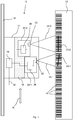
- Fig. 1 shows a schematic representation of an optoelectronic position detection system 10, which detects the position of a sensor device 11 along a travel path on the basis of a scale 12 with position marks 14.
- the sensor device 11 is in operation in relative movement to the scale 12, for example, because the sensor device 11 is attached to a vehicle and the scale 12 on a wall or on the ground along the intended route. Frequently the movement (direction 16) of the sensor device 11 or of the vehicle is forcibly guided in a linear manner, for example by rails 18. Then, the scale 12 can be mounted at a defined distance along the forced operation.
- the sensor device 11 has two identically designed sensor units 20-1 and 20-2. Each of the sensor units has a light receiver 22 for generating received signals from received light.
- the light receiver 22 may be an image sensor, for example a pixel-resolved matrix or line-shaped arrangement of light-receiving elements in CCD or CMOS technology.
- the sensor unit 20 it is also possible, for example, for the sensor unit 20 to be a scanner which emits and receives again a read beam via a rotating mirror or a polygon wheel mirror and thus scans the respective section of the scale 12. Such a reading beam is in Fig. 1 denoted by 23-1 and 23-2 respectively.
- the bright-dark signal of the scanning delivers after a A / D conversion, a line of pixels per scan, which are considered here as image data as the images of an image sensor.
- Each sensor unit 20-1 or 20-2 has a respective viewing area 24-1 or 24-2 for optical detection of the position markers 14 located in the viewing area.
- the sensor units 20-1 and 20-2 are thus arranged in the sensor device 11 and the sensor device 11 and the scale 12 are arranged relative to one another such that the first sensor unit 20-1 always detects at least two of the position marks 14 and the second sensor unit 20-2 always detects three other position marks 14.
- the image data is transferred from the light receiver 22 to an evaluation unit 26.
- the position information contained in the position marks 14 is decoded from the image data in a manner known per se.
- the position marks 14 contain, for example, a metric position information or a distance information with respect to a reference, preferably in absolute coding. In a conceivable incremental coding, the sensor device 11 can determine its position only relative to an initial position or an initial reference travel is required.
- the position information provided by the evaluation units 26 are supplied to a safety controller 28, in which of the two different position information a fail-safe position information is generated. Depending on this fail-safe position information, a stop signal, emergency stop signal or the like or the fail-safe position information itself can be output at an output 30.
- the sensor device 11 From the position information, the sensor device 11 derives its own position using known or previously learned parameters such as perspective and distance to the scale 12. This conversion can be avoided if the position marks 14 already encoded encoded on the sensor device 11 position information. When the scale 12 is perpendicular orientation of the sensor 10 and position determination in one dimension, the conversion eliminates anyway. From at least two position determinations and the associated times, a speed of the relative movement between sensor device 11 and scale 12 can also be estimated.
- the sensor units 20-1 and 20-2 are arranged in fixed spatial relationship and at a distance in the direction of movement 16 to each other.
- the sensor units 20-1 and 20-2 are mounted on a common support 32.
- the holder 32 may be a solid mounting block which is fixed in a housing of the sensor device 11, wherein the mounting block may have stops for the defined definition of the sensor units 20-1 and 20-2.
- the sensor units 20-1 and 20-2 may be tilted against each other, as may be due to the non-parallelism of the in Fig. 1 illustrated read lines 23-1 and 23-2 should be clarified. In this way, the position marks 14 are seen from the sensor units 20-1 and 20-2 from different angles.
- the method according to the invention for fail-safe position determination comprises the following steps: First, the position marks 14 are optically detected on a positioning scale 12 with the sensor device. In the evaluation units 26 of the sensor units 20-1 and 20-2, the position information coded in the position markers 14 is decoded and this position information given to the safety controller 28. In the safety controller 28 it is checked whether the difference of the two position information is plausible with the spatial distance of the two sensor units 20-1 and 20-2. If the plausibility is given, from the two position information failsafe position information for the sensor device won. Optionally, this failsafe position information is output or otherwise processed. For example, the fail-safe position information could be used to generate a security signal depending thereon.
Landscapes
- Physics & Mathematics (AREA)
- General Physics & Mathematics (AREA)
- Length Measuring Devices By Optical Means (AREA)
- Length Measuring Devices With Unspecified Measuring Means (AREA)
Claims (5)
- Système optoélectronique de détection de position (10) pour la détermination de position, comprenant une échelle de positionnement (12) avec des marques de position (14) et un dispositif de détection (11) avec deux unités de détection (20-1, 20-2) constituées chacune d'un récepteur de lumière (22) pour générer des signaux reçus de lumière reçue réfléchie par les marques de position (14) et une unité d'évaluation (26) pour évaluer les signaux reçus et délivrer les résultats d'évaluation, caractérisé en ce que les unités de détection (20-1, 20-2) sont conçus de manière identique, et en ce que les unités de capteurs (20-1, 20-2) sont disposées dans une relation spatiale fixe et à distance l'une de l'autre, de sorte qu'une première (20-1) des deux unités de capteurs détecte toujours au moins deux marques de position (14) et la seconde (20-2) des unités de capteurs détecte toujours trois autres marques de position (14), et que les résultats des évaluations sont transmis à un contrôleur de sécurité (28) qui est conçu pour générer des informations de position sans erreur à partir des résultats des analyses.
- Système selon la revendication 1, caractérisé en ce que les unités de capteurs sont inclinées l'une par rapport à l'autre de sorte que les marques de position sont vues par les unités de capteurs sous différents angles de vue.
- Système selon l'une des revendications précédentes, caractérisé en ce que les unités de capteurs sont montées sur un support commun.
- Système selon l'une des revendications précédentes, caractérisé en ce que les résultats d'analyse sont des résultats de position et en ce que le contrôleur de sécurité vérifie la plausibilité des deux positions déterminées.
- Procédé de détermination de position de sécurité, dans lequel des marques de position (14) sont détectées sur une échelle de positionnement (12) avec un système de détection de position optoélectronique (10) selon l'une des revendications précédentes et dans lequel des informations de position codées dans les marques de position (14) sont lues et traitées dans un contrôleur de sécurité (28) en une indication de position de sécurité, le contrôleur de sécurité (28) vérifiant si les informations de position sont plausibles avec la distance dans le vide des capteurs (20-1, 20-2).
Applications Claiming Priority (1)
| Application Number | Priority Date | Filing Date | Title |
|---|---|---|---|
| DE102017100506.4A DE102017100506A1 (de) | 2017-01-12 | 2017-01-12 | Optoelektronisches Positionserfassungssystem und Verfahren zur Positionsbestimmung |
Publications (2)
| Publication Number | Publication Date |
|---|---|
| EP3348967A1 EP3348967A1 (fr) | 2018-07-18 |
| EP3348967B1 true EP3348967B1 (fr) | 2019-05-22 |
Family
ID=60923374
Family Applications (1)
| Application Number | Title | Priority Date | Filing Date |
|---|---|---|---|
| EP18150223.8A Active EP3348967B1 (fr) | 2017-01-12 | 2018-01-03 | Système de détection de position optoélectronique et procédé de détermination de la position |
Country Status (3)
| Country | Link |
|---|---|
| US (1) | US20180195882A1 (fr) |
| EP (1) | EP3348967B1 (fr) |
| DE (1) | DE102017100506A1 (fr) |
Families Citing this family (1)
| Publication number | Priority date | Publication date | Assignee | Title |
|---|---|---|---|---|
| DE102024118757B3 (de) * | 2024-07-02 | 2025-07-10 | Dr. Ing. H.C. F. Porsche Aktiengesellschaft | Verfahren zum Ansteuern von zumindest einem Frontscheinwerfer eines Kraftfahrzeugs sowie Kraftfahrzeug mit einem Frontscheinwerfersystem |
Family Cites Families (14)
| Publication number | Priority date | Publication date | Assignee | Title |
|---|---|---|---|---|
| DE19604871A1 (de) * | 1996-02-10 | 1997-08-14 | Heidenhain Gmbh Dr Johannes | Positionsmeßeinrichtung |
| DE19628765B4 (de) * | 1996-07-17 | 2007-04-05 | Braun, Paul-Wilhelm, Dipl.-Ing. | Verfahren und Vorrichtung zur Positionsbestimmung von nicht-geradlinig bewegten, insbesondere rotierenden Maschinenteilen |
| JP2001004319A (ja) * | 1999-06-24 | 2001-01-12 | Mitsutoyo Corp | 線形測長器及び測長方法 |
| US6435315B1 (en) * | 2000-12-11 | 2002-08-20 | Otis Elevator Company | Absolute position reference system for an elevator |
| DE10211779B4 (de) * | 2002-03-16 | 2005-03-31 | Leuze Electronic Gmbh & Co Kg | Optoelektronische Vorrichtung |
| DE102005047658B4 (de) | 2005-10-05 | 2008-03-20 | Leuze Electronic Gmbh + Co. Kg | Vorrichtung zur Positionsbestimmung |
| US7659996B2 (en) * | 2006-11-08 | 2010-02-09 | Ricoh Company, Ltd. | Relative position detection device and detector for rotary body and image forming apparatus including the relative position detection device |
| DE102008032786A1 (de) * | 2008-07-11 | 2010-06-10 | Pepperl + Fuchs Gmbh | Vorrichtung und Verfahren zum Bestimmen einer Position eines Fahrzeugs |
| JP5761910B2 (ja) * | 2009-12-17 | 2015-08-12 | キヤノン株式会社 | 速度検出装置 |
| WO2011089893A1 (fr) * | 2010-01-20 | 2011-07-28 | キヤノン株式会社 | Dispositif de détection de déplacement et procédé de correction d'erreur de l'échelle du dispositif de détection de déplacement |
| DE102010008957A1 (de) * | 2010-02-19 | 2011-08-25 | FusionSystems GmbH, 09125 | Positionsbestimmung mittels optischer Kode-Schiene (Astropos) |
| JP5882590B2 (ja) * | 2011-02-28 | 2016-03-09 | キヤノン株式会社 | 光学式エンコーダおよび光学式エンコーダを有する装置 |
| JP6245941B2 (ja) * | 2012-12-10 | 2017-12-13 | Dmg森精機株式会社 | 変位検出装置 |
| DE202014100689U1 (de) * | 2014-02-17 | 2015-06-01 | Sick Ag | Optoelektronische Vorrichtung zur Positionsbestimmung |
-
2017
- 2017-01-12 DE DE102017100506.4A patent/DE102017100506A1/de not_active Withdrawn
-
2018
- 2018-01-03 EP EP18150223.8A patent/EP3348967B1/fr active Active
- 2018-01-10 US US15/867,291 patent/US20180195882A1/en not_active Abandoned
Non-Patent Citations (1)
| Title |
|---|
| None * |
Also Published As
| Publication number | Publication date |
|---|---|
| EP3348967A1 (fr) | 2018-07-18 |
| US20180195882A1 (en) | 2018-07-12 |
| DE102017100506A1 (de) | 2018-07-12 |
Similar Documents
| Publication | Publication Date | Title |
|---|---|---|
| DE19910933B4 (de) | Vorrichtung zur Positionierung eines Fahrzeugs | |
| EP2037226B1 (fr) | Procédé et dispositif destinés à la détermination de la position d`un véhicule, programme informatique et produit de programme informatique | |
| EP1046925B1 (fr) | Dispositif optoélectronique | |
| EP2083209B1 (fr) | Système de sécurité destiné à la mesure sans contact de voies et/ou de vitesses | |
| EP1660393B1 (fr) | Dispositif de controle d'une installation de convoyage | |
| EP2012253B1 (fr) | Lecture d'informations à l'aide d'un capteur optoélectronique et d'un lecteur RFID | |
| EP2078590B1 (fr) | Dispositif de vissage et procédé de surveillance de processus de vissage | |
| DE10312972B3 (de) | Optischer Sensor | |
| EP1586866B1 (fr) | Procédé optoélectronique de déterminer la position d'un capteur pour compenser des erreurs d'ajustement | |
| EP3348967B1 (fr) | Système de détection de position optoélectronique et procédé de détermination de la position | |
| DE102020104603B4 (de) | Steuereinheit und Verfahren zum Betrieb eines Fördermittels | |
| EP3736605A2 (fr) | Balayeur laser de sécurité et procédé | |
| DE102005047658A1 (de) | Vorrichtung zur Positionsbestimmung | |
| DE102008032786A1 (de) | Vorrichtung und Verfahren zum Bestimmen einer Position eines Fahrzeugs | |
| EP3367128B1 (fr) | Dispositif de surveillance | |
| EP3825731B1 (fr) | Capteur optoélectronique de sécurité et procédé de détermination sécurisée de position propre | |
| EP3483810B1 (fr) | Système de surveillance de l'occupation de compartiment | |
| EP2932188A1 (fr) | Appareil comprenant une partie d'appareil mobile, en particulier appareil de mesure de coordonnées ou machine-outil | |
| EP3680624B2 (fr) | Dispositif de détection | |
| EP1315982A1 (fr) | Dispositif de mesure de distance au laser pour systemes anti-collision | |
| DE4424008A1 (de) | Optoelektronische Vorrichtung zum Erkennen von Marken | |
| EP0487887B1 (fr) | Jante pour véhicule automobile ayant une structure d'un code et décodeur | |
| DE10225546B4 (de) | Optoelektronische Vorrichtung | |
| EP4451003A1 (fr) | Agencement de capteur et procédé de fonctionnement d'un agencement de capteur | |
| EP4737863A1 (fr) | Dispositif et procédé de détermination d'une position |
Legal Events
| Date | Code | Title | Description |
|---|---|---|---|
| PUAI | Public reference made under article 153(3) epc to a published international application that has entered the european phase |
Free format text: ORIGINAL CODE: 0009012 |
|
| STAA | Information on the status of an ep patent application or granted ep patent |
Free format text: STATUS: THE APPLICATION HAS BEEN PUBLISHED |
|
| AK | Designated contracting states |
Kind code of ref document: A1 Designated state(s): AL AT BE BG CH CY CZ DE DK EE ES FI FR GB GR HR HU IE IS IT LI LT LU LV MC MK MT NL NO PL PT RO RS SE SI SK SM TR |
|
| AX | Request for extension of the european patent |
Extension state: BA ME |
|
| STAA | Information on the status of an ep patent application or granted ep patent |
Free format text: STATUS: REQUEST FOR EXAMINATION WAS MADE |
|
| 17P | Request for examination filed |
Effective date: 20181114 |
|
| RBV | Designated contracting states (corrected) |
Designated state(s): AL AT BE BG CH CY CZ DE DK EE ES FI FR GB GR HR HU IE IS IT LI LT LU LV MC MK MT NL NO PL PT RO RS SE SI SK SM TR |
|
| GRAP | Despatch of communication of intention to grant a patent |
Free format text: ORIGINAL CODE: EPIDOSNIGR1 |
|
| STAA | Information on the status of an ep patent application or granted ep patent |
Free format text: STATUS: GRANT OF PATENT IS INTENDED |
|
| GRAS | Grant fee paid |
Free format text: ORIGINAL CODE: EPIDOSNIGR3 |
|
| GRAA | (expected) grant |
Free format text: ORIGINAL CODE: 0009210 |
|
| STAA | Information on the status of an ep patent application or granted ep patent |
Free format text: STATUS: THE PATENT HAS BEEN GRANTED |
|
| INTG | Intention to grant announced |
Effective date: 20190325 |
|
| AK | Designated contracting states |
Kind code of ref document: B1 Designated state(s): AL AT BE BG CH CY CZ DE DK EE ES FI FR GB GR HR HU IE IS IT LI LT LU LV MC MK MT NL NO PL PT RO RS SE SI SK SM TR |
|
| REG | Reference to a national code |
Ref country code: GB Ref legal event code: FG4D Free format text: NOT ENGLISH |
|
| REG | Reference to a national code |
Ref country code: CH Ref legal event code: EP |
|
| REG | Reference to a national code |
Ref country code: IE Ref legal event code: FG4D Free format text: LANGUAGE OF EP DOCUMENT: GERMAN |
|
| REG | Reference to a national code |
Ref country code: DE Ref legal event code: R096 Ref document number: 502018000033 Country of ref document: DE |
|
| REG | Reference to a national code |
Ref country code: AT Ref legal event code: REF Ref document number: 1136669 Country of ref document: AT Kind code of ref document: T Effective date: 20190615 |
|
| REG | Reference to a national code |
Ref country code: NL Ref legal event code: MP Effective date: 20190522 |
|
| REG | Reference to a national code |
Ref country code: LT Ref legal event code: MG4D |
|
| PG25 | Lapsed in a contracting state [announced via postgrant information from national office to epo] |
Ref country code: AL Free format text: LAPSE BECAUSE OF FAILURE TO SUBMIT A TRANSLATION OF THE DESCRIPTION OR TO PAY THE FEE WITHIN THE PRESCRIBED TIME-LIMIT Effective date: 20190522 Ref country code: ES Free format text: LAPSE BECAUSE OF FAILURE TO SUBMIT A TRANSLATION OF THE DESCRIPTION OR TO PAY THE FEE WITHIN THE PRESCRIBED TIME-LIMIT Effective date: 20190522 Ref country code: PT Free format text: LAPSE BECAUSE OF FAILURE TO SUBMIT A TRANSLATION OF THE DESCRIPTION OR TO PAY THE FEE WITHIN THE PRESCRIBED TIME-LIMIT Effective date: 20190922 Ref country code: SE Free format text: LAPSE BECAUSE OF FAILURE TO SUBMIT A TRANSLATION OF THE DESCRIPTION OR TO PAY THE FEE WITHIN THE PRESCRIBED TIME-LIMIT Effective date: 20190522 Ref country code: NO Free format text: LAPSE BECAUSE OF FAILURE TO SUBMIT A TRANSLATION OF THE DESCRIPTION OR TO PAY THE FEE WITHIN THE PRESCRIBED TIME-LIMIT Effective date: 20190822 Ref country code: HR Free format text: LAPSE BECAUSE OF FAILURE TO SUBMIT A TRANSLATION OF THE DESCRIPTION OR TO PAY THE FEE WITHIN THE PRESCRIBED TIME-LIMIT Effective date: 20190522 Ref country code: NL Free format text: LAPSE BECAUSE OF FAILURE TO SUBMIT A TRANSLATION OF THE DESCRIPTION OR TO PAY THE FEE WITHIN THE PRESCRIBED TIME-LIMIT Effective date: 20190522 Ref country code: LT Free format text: LAPSE BECAUSE OF FAILURE TO SUBMIT A TRANSLATION OF THE DESCRIPTION OR TO PAY THE FEE WITHIN THE PRESCRIBED TIME-LIMIT Effective date: 20190522 Ref country code: FI Free format text: LAPSE BECAUSE OF FAILURE TO SUBMIT A TRANSLATION OF THE DESCRIPTION OR TO PAY THE FEE WITHIN THE PRESCRIBED TIME-LIMIT Effective date: 20190522 |
|
| PG25 | Lapsed in a contracting state [announced via postgrant information from national office to epo] |
Ref country code: LV Free format text: LAPSE BECAUSE OF FAILURE TO SUBMIT A TRANSLATION OF THE DESCRIPTION OR TO PAY THE FEE WITHIN THE PRESCRIBED TIME-LIMIT Effective date: 20190522 Ref country code: RS Free format text: LAPSE BECAUSE OF FAILURE TO SUBMIT A TRANSLATION OF THE DESCRIPTION OR TO PAY THE FEE WITHIN THE PRESCRIBED TIME-LIMIT Effective date: 20190522 Ref country code: BG Free format text: LAPSE BECAUSE OF FAILURE TO SUBMIT A TRANSLATION OF THE DESCRIPTION OR TO PAY THE FEE WITHIN THE PRESCRIBED TIME-LIMIT Effective date: 20190822 Ref country code: GR Free format text: LAPSE BECAUSE OF FAILURE TO SUBMIT A TRANSLATION OF THE DESCRIPTION OR TO PAY THE FEE WITHIN THE PRESCRIBED TIME-LIMIT Effective date: 20190823 |
|
| PG25 | Lapsed in a contracting state [announced via postgrant information from national office to epo] |
Ref country code: DK Free format text: LAPSE BECAUSE OF FAILURE TO SUBMIT A TRANSLATION OF THE DESCRIPTION OR TO PAY THE FEE WITHIN THE PRESCRIBED TIME-LIMIT Effective date: 20190522 Ref country code: SK Free format text: LAPSE BECAUSE OF FAILURE TO SUBMIT A TRANSLATION OF THE DESCRIPTION OR TO PAY THE FEE WITHIN THE PRESCRIBED TIME-LIMIT Effective date: 20190522 Ref country code: EE Free format text: LAPSE BECAUSE OF FAILURE TO SUBMIT A TRANSLATION OF THE DESCRIPTION OR TO PAY THE FEE WITHIN THE PRESCRIBED TIME-LIMIT Effective date: 20190522 Ref country code: CZ Free format text: LAPSE BECAUSE OF FAILURE TO SUBMIT A TRANSLATION OF THE DESCRIPTION OR TO PAY THE FEE WITHIN THE PRESCRIBED TIME-LIMIT Effective date: 20190522 Ref country code: RO Free format text: LAPSE BECAUSE OF FAILURE TO SUBMIT A TRANSLATION OF THE DESCRIPTION OR TO PAY THE FEE WITHIN THE PRESCRIBED TIME-LIMIT Effective date: 20190522 |
|
| RAP2 | Party data changed (patent owner data changed or rights of a patent transferred) |
Owner name: SICK AG |
|
| REG | Reference to a national code |
Ref country code: DE Ref legal event code: R097 Ref document number: 502018000033 Country of ref document: DE |
|
| PG25 | Lapsed in a contracting state [announced via postgrant information from national office to epo] |
Ref country code: SM Free format text: LAPSE BECAUSE OF FAILURE TO SUBMIT A TRANSLATION OF THE DESCRIPTION OR TO PAY THE FEE WITHIN THE PRESCRIBED TIME-LIMIT Effective date: 20190522 |
|
| PLBE | No opposition filed within time limit |
Free format text: ORIGINAL CODE: 0009261 |
|
| STAA | Information on the status of an ep patent application or granted ep patent |
Free format text: STATUS: NO OPPOSITION FILED WITHIN TIME LIMIT |
|
| PG25 | Lapsed in a contracting state [announced via postgrant information from national office to epo] |
Ref country code: TR Free format text: LAPSE BECAUSE OF FAILURE TO SUBMIT A TRANSLATION OF THE DESCRIPTION OR TO PAY THE FEE WITHIN THE PRESCRIBED TIME-LIMIT Effective date: 20190522 |
|
| 26N | No opposition filed |
Effective date: 20200225 |
|
| PG25 | Lapsed in a contracting state [announced via postgrant information from national office to epo] |
Ref country code: PL Free format text: LAPSE BECAUSE OF FAILURE TO SUBMIT A TRANSLATION OF THE DESCRIPTION OR TO PAY THE FEE WITHIN THE PRESCRIBED TIME-LIMIT Effective date: 20190522 |
|
| PG25 | Lapsed in a contracting state [announced via postgrant information from national office to epo] |
Ref country code: MC Free format text: LAPSE BECAUSE OF FAILURE TO SUBMIT A TRANSLATION OF THE DESCRIPTION OR TO PAY THE FEE WITHIN THE PRESCRIBED TIME-LIMIT Effective date: 20190522 |
|
| REG | Reference to a national code |
Ref country code: BE Ref legal event code: MM Effective date: 20200131 |
|
| PG25 | Lapsed in a contracting state [announced via postgrant information from national office to epo] |
Ref country code: LU Free format text: LAPSE BECAUSE OF NON-PAYMENT OF DUE FEES Effective date: 20200103 |
|
| PG25 | Lapsed in a contracting state [announced via postgrant information from national office to epo] |
Ref country code: BE Free format text: LAPSE BECAUSE OF NON-PAYMENT OF DUE FEES Effective date: 20200131 |
|
| PG25 | Lapsed in a contracting state [announced via postgrant information from national office to epo] |
Ref country code: IE Free format text: LAPSE BECAUSE OF NON-PAYMENT OF DUE FEES Effective date: 20200103 |
|
| REG | Reference to a national code |
Ref country code: CH Ref legal event code: PL |
|
| PG25 | Lapsed in a contracting state [announced via postgrant information from national office to epo] |
Ref country code: CH Free format text: LAPSE BECAUSE OF NON-PAYMENT OF DUE FEES Effective date: 20210131 Ref country code: LI Free format text: LAPSE BECAUSE OF NON-PAYMENT OF DUE FEES Effective date: 20210131 |
|
| PG25 | Lapsed in a contracting state [announced via postgrant information from national office to epo] |
Ref country code: MT Free format text: LAPSE BECAUSE OF FAILURE TO SUBMIT A TRANSLATION OF THE DESCRIPTION OR TO PAY THE FEE WITHIN THE PRESCRIBED TIME-LIMIT Effective date: 20190522 Ref country code: CY Free format text: LAPSE BECAUSE OF FAILURE TO SUBMIT A TRANSLATION OF THE DESCRIPTION OR TO PAY THE FEE WITHIN THE PRESCRIBED TIME-LIMIT Effective date: 20190522 |
|
| PG25 | Lapsed in a contracting state [announced via postgrant information from national office to epo] |
Ref country code: MK Free format text: LAPSE BECAUSE OF FAILURE TO SUBMIT A TRANSLATION OF THE DESCRIPTION OR TO PAY THE FEE WITHIN THE PRESCRIBED TIME-LIMIT Effective date: 20190522 Ref country code: IS Free format text: LAPSE BECAUSE OF FAILURE TO SUBMIT A TRANSLATION OF THE DESCRIPTION OR TO PAY THE FEE WITHIN THE PRESCRIBED TIME-LIMIT Effective date: 20190922 |
|
| GBPC | Gb: european patent ceased through non-payment of renewal fee |
Effective date: 20220103 |
|
| PG25 | Lapsed in a contracting state [announced via postgrant information from national office to epo] |
Ref country code: GB Free format text: LAPSE BECAUSE OF NON-PAYMENT OF DUE FEES Effective date: 20220103 |
|
| PG25 | Lapsed in a contracting state [announced via postgrant information from national office to epo] |
Ref country code: SI Free format text: LAPSE BECAUSE OF FAILURE TO SUBMIT A TRANSLATION OF THE DESCRIPTION OR TO PAY THE FEE WITHIN THE PRESCRIBED TIME-LIMIT Effective date: 20190522 |
|
| REG | Reference to a national code |
Ref country code: AT Ref legal event code: MM01 Ref document number: 1136669 Country of ref document: AT Kind code of ref document: T Effective date: 20230103 |
|
| PG25 | Lapsed in a contracting state [announced via postgrant information from national office to epo] |
Ref country code: AT Free format text: LAPSE BECAUSE OF NON-PAYMENT OF DUE FEES Effective date: 20230103 |
|
| PG25 | Lapsed in a contracting state [announced via postgrant information from national office to epo] |
Ref country code: AT Free format text: LAPSE BECAUSE OF NON-PAYMENT OF DUE FEES Effective date: 20230103 |
|
| PGFP | Annual fee paid to national office [announced via postgrant information from national office to epo] |
Ref country code: DE Payment date: 20260120 Year of fee payment: 9 |
|
| PGFP | Annual fee paid to national office [announced via postgrant information from national office to epo] |
Ref country code: AT Payment date: 20260410 Year of fee payment: 5 |
|
| PGFP | Annual fee paid to national office [announced via postgrant information from national office to epo] |
Ref country code: IT Payment date: 20260130 Year of fee payment: 9 |
|
| PGFP | Annual fee paid to national office [announced via postgrant information from national office to epo] |
Ref country code: FR Payment date: 20260127 Year of fee payment: 9 |