EP3368832B1 - Chauffage portatif pour des petites quantités de produit de consommation - Google Patents
Chauffage portatif pour des petites quantités de produit de consommation Download PDFInfo
- Publication number
- EP3368832B1 EP3368832B1 EP16860865.1A EP16860865A EP3368832B1 EP 3368832 B1 EP3368832 B1 EP 3368832B1 EP 16860865 A EP16860865 A EP 16860865A EP 3368832 B1 EP3368832 B1 EP 3368832B1
- Authority
- EP
- European Patent Office
- Prior art keywords
- flexible container
- reaction chamber
- piercing element
- chemical reactant
- liquid chemical
- Prior art date
- Legal status (The legal status is an assumption and is not a legal conclusion. Google has not performed a legal analysis and makes no representation as to the accuracy of the status listed.)
- Active
Links
Images




Classifications
-
- B—PERFORMING OPERATIONS; TRANSPORTING
- B65—CONVEYING; PACKING; STORING; HANDLING THIN OR FILAMENTARY MATERIAL
- B65D—CONTAINERS FOR STORAGE OR TRANSPORT OF ARTICLES OR MATERIALS, e.g. BAGS, BARRELS, BOTTLES, BOXES, CANS, CARTONS, CRATES, DRUMS, JARS, TANKS, HOPPERS, FORWARDING CONTAINERS; ACCESSORIES, CLOSURES, OR FITTINGS THEREFOR; PACKAGING ELEMENTS; PACKAGES
- B65D81/00—Containers, packaging elements, or packages, for contents presenting particular transport or storage problems, or adapted to be used for non-packaging purposes after removal of contents
- B65D81/34—Containers, packaging elements, or packages, for contents presenting particular transport or storage problems, or adapted to be used for non-packaging purposes after removal of contents for packaging foodstuffs or other articles intended to be cooked or heated within the package
- B65D81/3484—Packages having self-contained heating means, e.g. heating generated by the reaction of two chemicals
-
- F—MECHANICAL ENGINEERING; LIGHTING; HEATING; WEAPONS; BLASTING
- F24—HEATING; RANGES; VENTILATING
- F24V—COLLECTION, PRODUCTION OR USE OF HEAT NOT OTHERWISE PROVIDED FOR
- F24V30/00—Apparatus or devices using heat produced by exothermal chemical reactions other than combustion
-
- A—HUMAN NECESSITIES
- A47—FURNITURE; DOMESTIC ARTICLES OR APPLIANCES; COFFEE MILLS; SPICE MILLS; SUCTION CLEANERS IN GENERAL
- A47J—KITCHEN EQUIPMENT; COFFEE MILLS; SPICE MILLS; APPARATUS FOR MAKING BEVERAGES
- A47J36/00—Parts, details or accessories of cooking-vessels
- A47J36/24—Warming devices
- A47J36/28—Warming devices generating the heat by exothermic reactions, e.g. heat released by the contact of unslaked lime with water
-
- B—PERFORMING OPERATIONS; TRANSPORTING
- B65—CONVEYING; PACKING; STORING; HANDLING THIN OR FILAMENTARY MATERIAL
- B65D—CONTAINERS FOR STORAGE OR TRANSPORT OF ARTICLES OR MATERIALS, e.g. BAGS, BARRELS, BOTTLES, BOXES, CANS, CARTONS, CRATES, DRUMS, JARS, TANKS, HOPPERS, FORWARDING CONTAINERS; ACCESSORIES, CLOSURES, OR FITTINGS THEREFOR; PACKAGING ELEMENTS; PACKAGES
- B65D2581/00—Containers, packaging elements, or packages, for contents presenting particular transport or storage problems, or adapted to be used for non-packaging purposes after removal of contents
- B65D2581/34—Containers, packaging elements, or packages, for contents presenting particular transport or storage problems, or adapted to be used for non-packaging purposes after removal of contents for packaging foodstuffs or other articles intended to be cooked or heated within
- B65D2581/3401—Cooking or heating method specially adapted to the contents of the package
- B65D2581/3402—Cooking or heating method specially adapted to the contents of the package characterised by the type of product to be heated or cooked
- B65D2581/3428—Cooking unusual food, i.e. none of the above foods
-
- B—PERFORMING OPERATIONS; TRANSPORTING
- B65—CONVEYING; PACKING; STORING; HANDLING THIN OR FILAMENTARY MATERIAL
- B65D—CONTAINERS FOR STORAGE OR TRANSPORT OF ARTICLES OR MATERIALS, e.g. BAGS, BARRELS, BOTTLES, BOXES, CANS, CARTONS, CRATES, DRUMS, JARS, TANKS, HOPPERS, FORWARDING CONTAINERS; ACCESSORIES, CLOSURES, OR FITTINGS THEREFOR; PACKAGING ELEMENTS; PACKAGES
- B65D2581/00—Containers, packaging elements, or packages, for contents presenting particular transport or storage problems, or adapted to be used for non-packaging purposes after removal of contents
- B65D2581/34—Containers, packaging elements, or packages, for contents presenting particular transport or storage problems, or adapted to be used for non-packaging purposes after removal of contents for packaging foodstuffs or other articles intended to be cooked or heated within
- B65D2581/3401—Cooking or heating method specially adapted to the contents of the package
- B65D2581/3429—Packages containing a secondary product to be cooked and discharged over the primary product
- B65D2581/3432—Packages containing a secondary product to be cooked and discharged over the primary product the secondary product, e.g. flavouring sauce, being enclosed in a second package
-
- C—CHEMISTRY; METALLURGY
- C09—DYES; PAINTS; POLISHES; NATURAL RESINS; ADHESIVES; COMPOSITIONS NOT OTHERWISE PROVIDED FOR; APPLICATIONS OF MATERIALS NOT OTHERWISE PROVIDED FOR
- C09K—MATERIALS FOR MISCELLANEOUS APPLICATIONS, NOT PROVIDED FOR ELSEWHERE
- C09K5/00—Heat-transfer, heat-exchange or heat-storage materials, e.g. refrigerants; Materials for the production of heat or cold by chemical reactions other than by combustion
- C09K5/16—Materials undergoing chemical reactions when used
-
- F—MECHANICAL ENGINEERING; LIGHTING; HEATING; WEAPONS; BLASTING
- F25—REFRIGERATION OR COOLING; COMBINED HEATING AND REFRIGERATION SYSTEMS; HEAT PUMP SYSTEMS; MANUFACTURE OR STORAGE OF ICE; LIQUEFACTION SOLIDIFICATION OF GASES
- F25D—REFRIGERATORS; COLD ROOMS; ICE-BOXES; COOLING OR FREEZING APPARATUS NOT OTHERWISE PROVIDED FOR
- F25D5/00—Devices using endothermic chemical reactions, e.g. using frigorific mixtures
Definitions
- This disclosure relates to a portable heater and, more particularly, relates to a portable heater for small quantities of consumer product.
- JPH07155261 discloses a providing a container with a heating matter housing part 2 which is arranged adjacent to a housing part for an object to be heated and has a heating matter comprising quick line and a water bag with encapsulated water. The quick line and water are brought into contact by pulling out a string provided on the water bag.
- the heater module has a housing that defines a reaction chamber.
- a rigid barrier is inside the reaction chamber and defines first and second portions thereof.
- a first reactant is inside the reaction chamber, and a flexible bag (with a second reactant) is in the first portion of the first chemical reactant. The first and second reactants react exothermically upon contact.
- a piercing element can pierce the flexible bag. After piercing, the a fluid path and one or more fluid channels carry the second reactant to a section of the first portion of the reaction chamber away from where the flexible bag is located.
- the systems and/or methods described herein are based on the interchange of heat between two masses by conduction across a common interface, so that the two masses tend toward the same temperature.
- one mass i.e., a heater
- a target material e.g., a food or other substance to be heated.
- the length of time during which the product may need to be heated by this means to reach a desired temperature can depend on a variety of factors including, for example, the product's viscosity, heat capacity, and thermal conductivity. If the hot mass (i.e., the heater) were designed to never exceed a chosen maximum temperature then the system could be used in virtually any condition of reasonable use without a significant risk of injury. It remains, however, to provide the hot mass on demand.
- the heater may be configured to produce heat by initiating a chemical reaction between a potassium permanganate solution and a glycerine-water solution. Moreover, this heating may involve heating of liquid masses by the reaction of potassium permanganate and glycerine in water. The final temperature of the water solution after completion of the reaction is generally governed by the concentration of the two chemicals in the reaction.
- the present application which employs the reactants above as one choice but can employ other heat producing reactions as well, describes the arrangement and activation of a heater appropriate for the purposes cited above.
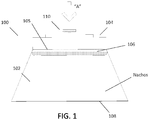
- FIG. 1 is a schematic, cross-sectional view of an exemplary portable, self-heating food container 100.
- the illustrated container 100 has a sealed food compartment 102 containing food (e.g., cheese 106 and nachos.
- the nachos are not shown in the figure, but would generally be located in the space below the cheese 106, labeled "Nachos"), and a heater module 104.
- the heater module 104 is physically and thermally coupled to the food compartment 102 by a common, heat transfer wall 105 between the heater module 104 and the food compartment 102.
- the heater module 104 is configured to generate heat when operated to heat and melt the cheese 106.
- the cheese when heated will melt and drip down over, and coat, the nachos.
- the apparatus 100 can be turned upside down (relative to the configuration shown in FIG. 1 ), the seal 108 (a removable cover) can be removed and the nachos, now coated with a warm or hot cheese can be enjoyed!
- the heater module 104 is easy to operate.
- the heater module has an activation button 110.
- To initiate heating a person merely needs to depress the button 110 (in direction indicated by the arrow "A"). A few moments later, heat begins to pass from the heater module 104 into the sealed food compartment 102 to heat and melt the cheese 106.
- the container 100 may be sold with a cover (not shown in the figure) over the activation button 110 that needs to be removed in order to access the button and initiate the heating.
- the illustrated self-heating container provides a great snack - nachos with hot melted cheese - anywhere, anytime, quickly and conveniently.
- FIG. 2 is a cross-sectional view of a container design 200 that details one way of implementing the self-heating container 100 of FIG. 1 .
- the illustrated implementation can, in some instances, be effective, there are drawbacks, many of which can be overcome by implementing one or more concepts also described herein.
- the illustrated apparatus 200 has a storage compartment 202 containing product to be heated (e.g., cheese 206 that will melt onto nachos).
- product to be heated e.g., cheese 206 that will melt onto nachos.
- the material to be heated in this case cheese dip
- a heater module 204 is physically and thermally coupled to the storage compartment 202 and is configured to produce heat when activated for heating the cheese in the storage compartment 202.
- the heater module 204 has a housing 207 that defines a reaction chamber.
- a first liquid chemical reactant 214 e.g., potassium permanganate solution
- a flexible container 212 e.g., a bag
- a second liquid chemical reactant 216 e.g., a glycerine solution
- the second liquid reactant 216 is configured to react exothermically with the first chemical reactant 214 upon contact.
- the flexible container 212 is located between a heat transfer surface 205 (for heat to flow from the heater module 204 to the storage compartment 202) and a base 220 of the heater module 204.
- a piercing element 218 (attached to an external activation button 210) is movable (in direction "A") to pierce the flexible container 212 and to enable at least some of the second liquid chemical reactant 216 to exit the flexible container 212 and mix with the first liquid chemical reactant 214.
- the activation button 210 has a tamper resistant feature (not shown) and features (also not shown) that cause the activation button (and piercing element 218) to latch or lock in the "in position” so, once depressed (e.g., moved in the direction of arrow "A"), it will remain in that position.
- the illustrated implementation can be somewhat effective. However, there are also several notable drawbacks, which are described below.
- Drawback One there is no strong force that helps eject the second liquid chemical solution 216 (e.g., the glycerine solution) from the flexible container 212. Indeed, in a typical implementation, some or most of that solution 216 remains in the flexible container 212 regardless of the nature of the hole created by the piercing element 218.
- the second liquid chemical solution 216 e.g., the glycerine solution
- the flexible container 212 is sometimes, or often, flexible enough to close around the piercing element 218 and effectively close (i.e., prevent flow through) the hole in the flexible container 212 created by the piercing element 218.
- the flexible container 212 in some instances, can seal against the base of the heater, effectively preventing or inhibiting the second liquid chemical reactant's 216 escape from the flexible container 212 into the first liquid chemical reactant 214.
- Drawback Five since the piercing element 218 crosses the boundary between the outside and inside of the heater module 204 housing 207, a leakage path exists, or may easily form, around the shaft of the piercing element 218.
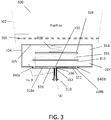
- FIG. 3 is a schematic, cross-sectional view of a container 300 that details a way of implementing an apparatus for heating a product according to the invention
- FIG. 4 is a close-up view showing part of the FIG. 3 container 300.
- the container 300 in FIG. 3 and in FIG. 4 is, in some ways, similar to the container 200 in FIG. 2 . As discussed herein, however, the container 300 in FIG. 3 is able to overcome or at least mitigate one or more (or all) of the above-mentioned, and perhaps other, drawbacks associated with the container 200 in FIG. 2 .
- the container 300 in FIG. 3 has a storage compartment 302 containing product to be heated (e.g., cheese 306 that will melt onto and mix with nachos).
- product to be heated e.g., cheese 306 that will melt onto and mix with nachos.
- the material to be heated in this case cheese dip
- a heater module 304 is physically and thermally coupled to the storage compartment 302 and is configured to produce heat when activated for heating at least the cheese in the storage compartment 302.
- the heater module 304 has a housing 305 that defines a reaction chamber.
- the reaction chamber has multiple walls, at least one of which is in direct physical contact with and thermally coupled to the storage compartment 302.
- first liquid chemical reactant 314 e.g., potassium permanganate solution
- flexible container 312 e.g., a plastic bag
- second liquid chemical reactant 316 e.g., a glycerine solution
- the first portion 324 of the reaction chamber includes the area above the rigid barrier 322, and the second portion 326 of the reaction chamber includes the area below the rigid barrier 322.
- fluid communications portals that fluidly connect the first portion 324 of the reaction chamber to the second portion 326 of the reaction chamber.
- reaction chamber should be construed broadly to include any section(s) of the heater module 304 (e.g., in the first portion 322 of the reaction chamber, the second portion 326 of the reaction chamber, or elsewhere) where any portion of the first liquid chemical reactant 314 or second liquid chemical reactant might be contained and/or react during normal system heating operations.
- the rigid barrier 322 may be any one of a variety of possible shapes and may define the first portion 324 of the reaction chamber and the second portion 326 of the reaction chamber to have any one of many possible different physical configurations. However, generally speaking, the rigid barrier 322 defines separate portions of the reaction chamber - the first portion 324 that physically accommodates the flexible container 312, and the second portion 326 that is physically separate from the first portion 324 during all phases of system operation and that generally does not include any part of the flexible container 312 during any phase of system operation. As discussed in further detail herein, the second portion 326 of the reaction chamber provides a clearly defined, unobscured fluid communication path for the second liquid chemical reactant to freely exit and move clear of the flexible container 312. In a typical implementation, this fluid communication path retains its shape, and remains substantially unobstructed, throughout system operation, even as the flexible container 312 empties and, therefore collapses.
- the flexible container 312 is positioned atop the rigid barrier 322 in the illustrated implementation, and is configured so that its outer side edges are close to, but do not overlap with, the fluid communications portals that fluidly connect the first portion 324 of the reaction chamber to the second portion 326 of the reaction chamber.
- the movable platform 328 in the illustrated implementation is configured to move in a downward direction (i.e., toward the flexible container 312) to help initiate heating and ensure thorough mixing of the liquid chemical reactants 314, 316.
- the movable platform 328 is in direct physical contact with the flexible container 312 and, therefore, any downward motion, such as might occur when the flexible container 312 is ruptured by a piercing element, will tend to collapse and help empty the flexible container 312.
- the movable platform 328 is large enough to cover all or at least a very substantial portion of the flexible container 312.
- the spring 330 at an opposite side of the movable platform 328 from the flexible container 312.
- the spring 330 in the illustrated implementation is in direct physical contact with the movable platform and with the upper wall (i.e., the heat transfer surface) of the reaction chamber.
- the spring 330 before the flexible container has been pierced, the spring 330 is in a highly compressed state and is urging the movable platform 328 in a downward direction (i.e., toward the flexible container 312).
- the spring 330 begins to extend, thereby causing the movable platform 328 to move in direction that helps to collapse the flexible container 312 (i.e., downward in FIG. 3 ), thereby encouraging the second liquid reactant 316 to exit the flexible container 312 and travel through fluid communication paths and/or channels defined by the rigid barrier 322 after the flexible container has been pierced.
- the spring 330 is typically configured so that it can move the movable platform 328 from its position (as shown in FIG. 3 ) atop the full and completely intact flexible container 312 all the way down to a position where it is pressing the fully deflated (and emptied) flexible container flat against the rigid barrier 322, so that only the fully deflated (and emptied) flexible container 312 remains between the movable platform 328 and the rigid barrier 322.
- the spring-loaded platform 328 presses down on the full and completely intact flexible container 312 to help keep the flexible container 312 in place between the movable platform 328, and the rigid barrier 322, and positioned so as to not cover any of the fluid communications portals that fluidly connect the first portion 324 of the reaction chamber to the second portion 326 of the reaction chamber.
- additional (or other) means may be used to help keep the flexible container 328 in place. These can include, for example, the use of an adhesive between the platform 328 and the flexible container 312 and/or between the upper surface of the rigid barrier 322 and the flexible container 312. Alternatively, these can include features formed in the bottom surface of the movable platform 328 and/or the upper surface of the rigid barrier configured to discourage sideways motion by the flexible container 312 within the reaction chamber.
- the illustrated self-heating system 300 has a piercing element 318 (attached to an external activation button 310) configured to pierce the flexible container 312 when the activation button 310 is pressed (i.e., moved in a direction indicated by arrow "A"). Piercing the flexible container 312, of course, enables the second liquid chemical reactant 216 to exit the flexible container 212 and mix with the first liquid chemical reactant 214.
- the self-heating system 300 includes one or more anti-tamper features (not shown) associated with the activation button 310.
- an anti-tamper feature may provide or facilitate tamper resistance, tamper detection, tamper response, and/or tamper evidence.
- the anti-tamper feature(s) are only tamper-evident.
- the self-heating system 300 includes one or more locking features (also not shown) that cause the activation button (and piercing element 218) to latch or lock into the depressed (or "heater activated") position. In those implementations, once the activation button has been pressed (i.e., moved in the direction of arrow "A" in FIG. 3 ), the activation button 310 and the piercing element 318 become locked in that position.
- the activation button 310 is exposed for user manipulation outside the housing 305 of the reaction chamber.
- the shaft of the activation button / piercing element therefore, extends essentially through the housing 305 and into the reaction chamber.
- an elastomeric seal 332 e.g., an o-ring
- the portion of the shaft of the activation button / piercing element that has the smooth cylindrical outer surface is long enough, in an axial direction, that the elastomeric seal remains in contact with and seals against the smooth cylindrical outer surface regardless of the piercing element's position relative to the housing (e.g., regardless of whether the activation button is fully extended or fully depressed).
- the piercing element 318 essentially forms a needle with a cylindrical body that has a pointed distal tip and a distal portion (at or very near the pointed distal tip) with a fluted external surface that has grooves 336 that extend some distance along the external surface in a substantially axial direction.
- a piercing element 318 can have one or more grooves 336.
- the grooves 336 will be evenly spaced from one another about a perimeter of the otherwise cylindrical piercing element shaft.
- the illustration shows two fluid distribution channels (338a, 338b) in the second portion 326 of the reaction chamber (i.e., the portion of the reaction chamber beneath the rigid barrier 322).
- Each of the illustrated fluid distribution channels (338a, 338b) extends from the roughly centrally located piercing element 318 outward in a substantially radial direction.
- these fluid distribution channels 338a, 338b extend in approximately opposite directions from the roughly centrally located piercing element 318.
- Each fluid distribution channel 338a, 338b terminates at a respective one of the fluid communications portals 340a, 340b that fluidly connects its associated fluid distribution channel 338a, or 338b to a portion of the second portion 326 of the reaction chamber that is away from the flexible container 312.
- each fluid distribution channel 338a, 338b (and its associated fluid communication portal) is configured to carry some portion of the second liquid chemical reactant released from the flexible container 312 to a section of the first portion of the reaction chamber away from where the flexible container 312 is located after the flexible container 312 has been ruptured.
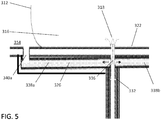
- the piercing element 318 is configured to move (when the activation button 310 if appropriately manipulated, e.g., pressed) in an axial direction from a first position, as shown in FIG. 4 (entirely outside the flexible container 312) to a second ("activated") position, as shown in FIG. 5 (extended into the flexible container 312). More particularly, when the piercing element 318 in the second ("activated") position ( FIG. 5 ), the pointed distal tip 334 of the piercing element 318 is inside the flexible container 312. Moreover, when the piercing element 318 is in the second ("activated") position ( FIG.
- the fluted portion of the piercing element shaft extends from inside the flexible container 312, through the rigid barrier 322, and to the fluid distribution channels 338a, 338b in the second portion 326 of the reaction chamber (beneath the rigid barrier).
- Each groove 336 in the fluted portion of the piercing element shaft is typically wide enough and deep enough to facilitate a relatively easy flow of the first liquid chemical reactant (e.g., the glycerine solution) out of the collapsing flexible container 312 and into the fluid distribution channels 338a, 338b.
- fluid distribution channels 338a, 338b in the illustrated implementation are configured to carry the second liquid chemical reactant to a section of the first portion of the reaction chamber away from where the flexible container 312 is located so that the flexible container 312 is not able to block the second liquid chemical reactant from entering the reaction chamber and mixing sufficiently with the first liquid chemical reactant.
- FIG. 6 is a partial, schematic, cross-sectional side view of a self-heating container 600 design that is similar in many respects to the self-heating container 300 shown in FIG. 3 and discussed herein above.
- the piercing element 618 in the container 600 of FIG. 6 is different than the piercing element 318 in the container 300 of FIG. 6 .
- the piercing element 618 in FIG. 6 essentially forms a needle with a hollow tubular body with an opening at or near a pointed distal end thereof and one or more openings in a sidewall thereof. Fluid can flow into the opening at or near the pointed distal end of the piercing element 618, through the hollow tubular body in an axial direction, and out through the one or more sidewall openings to escape the flexible container 312.
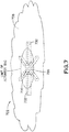
- Fig. 7 is a perspective, partial cut-away view of an exemplary distribution manifold 722 that may define fluid communication paths for the first liquid chemical reactant (e.g., the activator).
- the illustrated manifold is formed in a base 738 (i.e., a lower surface) of a heater module (e.g., 304). It includes a piercer hole 728, a plenum 730 and six slots 732 (or fluid distribution channels) that extend radially outward from the centrally-disposed plenum 730.
- the piercer hole 728 is a substantially cylindrical hole that extends all the through the base and, in the illustrated implementation, is centered relative to the substantially cylindrical concentric plenum 730.
- the plenum 730 is larger than the piercer hole 728 and extends only partially through the base.
- the slots 732 also extend only partially through the base.
- the figure shows a dashed line that shows the limit of where the activator bag (i.e., the flexible container) can cover. Notably, the outer, distal edges of the slots extend beyond that limit. This helps ensure that, during operation, the activator bag will not be able to block any fluid flow paths through the slots 732.
- the activator bag i.e., the flexible container
- the distribution manifold is formed directly in a bottom surface of the heater module.
- the piercer hole may be drilled through the base, the plenum may be partially drilled into an upper surface (i.e., facing the reaction chamber) of the base and the slots may be similarly partially drilled or etched into the upper surface of the base.
- the distribution manifold may be a separate piece that is attached to the heater module.
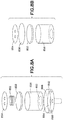
- FIG. 8A is an exploded view showing part of an alternative heater module arrangement.
- the heater module includes a piston and cylinder assembly in lieu of the container and spring-loaded platform in FIG. 3 , for example.
- the illustrated implementation includes a cylinder 858 and a piston 850 with a cup seal that is sized to move up and down inside the cylinder 858.
- a spring 852 above the piston 852 that gets compressed, when assembled, between the piston 850 and a vented base cover 854 at the top of the cylinder.
- a membrane 860 that seals the bottom of the cylinder and one of the reactants would be inside the cylinder until the heater is activated.
- the vented base cover prevents a vacuum from forming behind the piston as it moves down through the cylinder.
- the distribution manifold 862 includes a hole 864 to accommodate a piercing element, a plenum 866 and a plurality of holes (or fluid distribution channels) 868 that extend in a radially outward direction from the plenum 866.
- the piercing element is configured to extend through the hole 864 and pierce the membrane 860 to initiate heating.
- FIG. 8B is an exploded view showing part of an alternative heater module arrangement.
- the arrangement in FIG. 8B is similar to the arrangement in FIG. 8A .
- the arrangement in FIG. 8B includes an air bag 856 to urge the piston in a downward direction instead of a spring.
- FIG. 9 presents a graph of the temperature history of a particular test. Shown are the temperatures of the heater and target. In this case, the substance being heated is milk chocolate.
- the specific size, shape and relative arrangement of components can vary considerably.
- Various different materials and chemicals may be used for the different components.
- the first liquid chemical reactant (e.g., the activator) is preferably in a bag.
- the bag may be replaced by a syringe-type of rigid container, or other type of container.
- Either chemical reactant can be provided in the bag, with the other outside the bag.
- an activation button is pressed to initiate heating.
- the activation element can be virtually any kind of activation element including, for example, a knob, a switch, etc.
- the spring may be replaced by an airbag or the like.
- the heating concepts can be applied to a wide variety of heating applications.
Landscapes
- Engineering & Computer Science (AREA)
- Chemical & Material Sciences (AREA)
- Chemical Kinetics & Catalysis (AREA)
- Food Science & Technology (AREA)
- Mechanical Engineering (AREA)
- Physics & Mathematics (AREA)
- Thermal Sciences (AREA)
- Combustion & Propulsion (AREA)
- General Engineering & Computer Science (AREA)
- Life Sciences & Earth Sciences (AREA)
- Cookers (AREA)
Claims (16)
- Appareil (100, 200, 300) pour chauffer un produit, l'appareil comprenant :un boîtier (207, 305) qui définit une chambre de réaction ;une barrière rigide (322) à l'intérieur de la chambre de réaction qui délimite une première partie (324) de la chambre de réaction d'une seconde partie (326) de la chambre de réaction ;un premier réactif chimique liquide (214, 314) à l'intérieur de la chambre de réaction ;un récipient flexible (212, 312) à l'intérieur de la première partie de la chambre de réaction, et immergé dans le premier réactif chimique liquide (214, 314), etun second réactif chimique liquide (216, 316) à l'intérieur du récipient flexible (212, 312) qui est configuré pour réagir de manière exothermique avec le premier réactif chimique (214, 314) suite au contact ;caractérisé en ce que l'appareil (300) comprend en outre :un élément de perçage (318) qui est mobile pour percer le récipient flexible (312) et pour aider à définir une trajectoire de communication du fluide depuis l'intérieur du récipient flexible (312) jusqu'à la seconde partie (326) de la chambre de réaction lorsqu'une extrémité distale de l'élément de perçage (318) est étendue dans le récipient flexible (312), etun ou plusieurs canaux de distribution de fluide (338a, 338b) dans la seconde partie (326) de la chambre de réaction, configurés pour transporter le second réactif chimique liquide (316) de la trajectoire de communication de fluide à une section de la première partie (324) de la chambre de réaction à distance de l'endroit où le récipient flexible (312) est positionné.
- Appareil selon la revendication 1, comprenant en outre :
une plateforme (328) configurée pour être en contact avec le récipient flexible (312) au niveau d'un côté opposé du récipient flexible (312) par rapport à l'élément de perçage (318) . - Appareil selon la revendication 2, comprenant en outre :
un ressort (330) ou coussin de sécurité gonflage configuré pour pousser la plateforme (328) dans une direction qui a tendance à replier le récipient flexible (312) après que l'élément de perçage (318) a percé le récipient flexible (312), encourageant ainsi le second réactif (316) à sortir du récipient flexible (312), à se déplacer à travers la trajectoire de communication de fluide et les un ou plusieurs canaux de distribution de fluide (338a, 338b) après que le récipient flexible (312) a été percé. - Appareil selon la revendication 1, dans lequel l'élément de perçage (318) comprend :une aiguille avec un corps tubulaire creux ayant une ouverture au niveau de ou à proximité de son extrémité distale, dans lequel l'ouverture se raccorde à une trajectoire de fluide qui s'étend de manière axiale à travers au moins une partie de l'aiguille et une ou plusieurs ouvertures dans une paroi latérale de l'aiguille le long de la trajectoire de fluide, ou bienune aiguille ayant un corps cylindrique avec sa partie distale qui a une surface externe cannelée.
- Appareil selon la revendication 4, comprenant en outre :
un bouton d'activation (110, 210, 310) exposé à l'extérieur du boîtier et raccordé à une extrémité proximale de l'élément de perçage (318). - Appareil selon la revendication 5, dans lequel l'élément de perçage (318) a une surface externe cylindrique lisse entre les une ou plusieurs ouvertures dans la paroi latérale ou la surface externe cannelée, et le bouton d'activation.
- Appareil selon la revendication 6, dans lequel une partie de l'élément de perçage (318) qui a la surface externe cylindrique lisse s'étend à travers une ouverture dans le boîtier (305), l'appareil comprenant en outre :un joint d'étanchéité élastomère (332) entre la surface externe cylindrique lisse de l'élément de perçage et le boîtier (305),dans lequel la surface externe cylindrique lisse est axialement assez longue de sorte que le joint d'étanchéité élastomère (332) reste en contact avec et réalise l'étanchéité contre la surface externe cylindrique lisse indépendamment de la position de l'élément de perçage (318) par rapport au boîtier (305).
- Appareil selon la revendication 1, comprenant en outre :
un mécanisme de verrouillage pour verrouiller le perçage en place une fois qu'il a atteint une position dans laquelle il a percé le récipient flexible (312) et établi la trajectoire de communication de fluide jusqu'à la seconde partie (326) de la chambre de réaction. - Appareil selon la revendication 1, dans lequel les un ou plusieurs canaux de distribution de fluide (338a, 338b) comprennent plusieurs canaux de distribution, et dans lequel chacun des canaux de distribution de fluide (338a, 338b) s'étend dans une direction radiale qui est différente des autres.
- Appareil selon la revendication 1, dans lequel le récipient flexible (312) est un sachet en plastique.
- Appareil selon la revendication 1, dans lequel le premier réactif chimique liquide (214, 314) comprend une solution de permanganate de potassium et dans lequel le second réactif chimique liquide (216, 316) comprend une solution de glycérine.
- Appareil selon la revendication 1, comprenant en outre :
un compartiment de stockage (202, 302) pour une substance alimentaire ou une autre substance à chauffer, dans lequel au moins une paroi du compartiment de stockage (202, 302) est en contact physique direct avec et couplé thermiquement à la chambre de réaction. - Appareil selon la revendication 12, comprenant en outre une substance fusible dans le compartiment de stockage (202, 302), dans lequel, suite au chauffage, la substance fusible fond et se mélange au moins partiellement avec et/ou recouvre l'aliment ou une autre substance à chauffer dans le compartiment de stockage (202, 302).
- Appareil selon la revendication 1, dans lequel les un ou plusieurs canaux de distribution de fluide (338a, 338b) sont configurés pour transporter le second réactif chimique liquide (316) jusqu'à une section de la première partie (324) de la chambre de réaction à distance de l'endroit où le récipient flexible (312) est positionné, de sorte que le récipient flexible (312) ne peut pas empêcher le second réactif chimique liquide (316) d'entrer dans la chambre de réaction et de se mélanger suffisamment avec le premier réactif chimique liquide (314).
- Appareil selon la revendication 1, comprenant :un compartiment de stockage (202, 302) contenant un ou plusieurs produits (206, 306) à chauffer ; etdans lequel :la chambre de réaction est à l'intérieur du boîtier (305) ;le récipient flexible (312) est un sachet flexible ; etl'élément de perçage (318) est mobile, grâce à un utilisateur, pour percer le sachet flexible.
- Appareil selon la revendication 1, dans lequel :
la seconde partie (326) de la chambre de réaction est séparée de la première partie (324) de la chambre de réaction par une barrière rigide (322).
Applications Claiming Priority (2)
| Application Number | Priority Date | Filing Date | Title |
|---|---|---|---|
| US201562248057P | 2015-10-29 | 2015-10-29 | |
| PCT/US2016/059296 WO2017075334A1 (fr) | 2015-10-29 | 2016-10-28 | Chauffage portatif pour des petites quantités de produit de consommation |
Publications (3)
| Publication Number | Publication Date |
|---|---|
| EP3368832A1 EP3368832A1 (fr) | 2018-09-05 |
| EP3368832A4 EP3368832A4 (fr) | 2019-05-22 |
| EP3368832B1 true EP3368832B1 (fr) | 2020-08-05 |
Family
ID=58631161
Family Applications (1)
| Application Number | Title | Priority Date | Filing Date |
|---|---|---|---|
| EP16860865.1A Active EP3368832B1 (fr) | 2015-10-29 | 2016-10-28 | Chauffage portatif pour des petites quantités de produit de consommation |
Country Status (7)
| Country | Link |
|---|---|
| US (2) | US10858171B2 (fr) |
| EP (1) | EP3368832B1 (fr) |
| CN (1) | CN108474592B (fr) |
| CA (1) | CA3042177C (fr) |
| CY (1) | CY1123523T1 (fr) |
| ES (1) | ES2828967T3 (fr) |
| WO (1) | WO2017075334A1 (fr) |
Families Citing this family (6)
| Publication number | Priority date | Publication date | Assignee | Title |
|---|---|---|---|---|
| EP3519320B1 (fr) * | 2016-09-29 | 2025-02-19 | Kellanova | Ensemble d'emballage de produits alimentaires et procédés associés |
| IT201900002391A1 (it) * | 2019-02-19 | 2020-08-19 | De Longhi Appliances S R L Div Commerciale Ariete | Elettrodomestico per la produzione di prodotti caseari |
| US12226046B2 (en) * | 2019-04-16 | 2025-02-18 | Tempra Technology, Inc. | Disposable baby bottle warmer for use anywhere |
| CN111674728B (zh) * | 2020-05-27 | 2022-01-18 | 中国农业科学院农产品加工研究所 | 一种非水激发的食品自加热装置 |
| US12522419B2 (en) | 2021-08-04 | 2026-01-13 | Andrew Jhonnie Spencer | Self-heating or self-cooling system and method |
| CN114313631B (zh) * | 2021-12-31 | 2023-05-16 | 浙江安友制罐有限公司 | 一种设有防尘扣盖的马口铁罐 |
Family Cites Families (33)
| Publication number | Priority date | Publication date | Assignee | Title |
|---|---|---|---|---|
| US2239410A (en) * | 1939-10-11 | 1941-04-22 | Bonat Harry | Method and means of producing heat by exothermic reaction |
| FR869290A (fr) * | 1940-09-26 | 1942-01-28 | Dispositif permettant d'obtenir, sans aucune aide extérieure et à un moment voulu, le chauffage ou la réfrigération de toutes substances, solides ou fluides | |
| CH517026A (fr) * | 1969-07-18 | 1971-12-31 | Stadex Ab | Dispositif de fermeture déchirable et utilisation de ce dispositif |
| US3653372A (en) * | 1969-12-12 | 1972-04-04 | Beverly Douglas | Chemically heated container |
| US3685507A (en) * | 1970-11-02 | 1972-08-22 | Readi Temp | Heat transfer unit |
| IT995140B (it) * | 1973-08-03 | 1975-11-10 | Grosso A | Contenitore autoscaldante per cibi precotti |
| JPS61253023A (ja) * | 1985-04-04 | 1986-11-10 | 旭化成株式会社 | 加熱容器 |
| FR2585336A1 (fr) * | 1985-07-23 | 1987-01-30 | Doukan Jacques | Barquette alimentaire comportant un dispositif de rechauffage par reaction exothermique de deux produits reactifs |
| US4773389A (en) * | 1986-02-19 | 1988-09-27 | Chori Company, Ltd. | Self-heating foodstuff container |
| US4867131A (en) * | 1989-03-01 | 1989-09-19 | Merwe Jacobus C V D | Combined heating dish and storage container for food |
| JPH07155261A (ja) * | 1993-12-03 | 1995-06-20 | Tadaichi Sakamoto | 加温容器 |
| JPH08240345A (ja) * | 1995-03-03 | 1996-09-17 | Hitachi Ltd | 発熱体および吸気加熱装置および暖房機および加熱装置 |
| US20040112367A1 (en) * | 2002-12-11 | 2004-06-17 | Mauro Zaninelli | Heating or chilling sack container |
| US7431837B2 (en) * | 2003-02-13 | 2008-10-07 | Ilc Dover Lp | Mixing vessel and method of use |
| GB2401789A (en) * | 2003-05-19 | 2004-11-24 | Keith Leslie Atkinson | Heat-activated vapour generating device |
| US20060169276A1 (en) * | 2004-03-15 | 2006-08-03 | Ontech Delaware Inc. | Tray for selectably heating or cooling the contents |
| US20060162344A1 (en) | 2004-03-15 | 2006-07-27 | Ontech Delaware Inc. | Container with module for heating or cooling the contents |
| US7025055B2 (en) * | 2004-03-15 | 2006-04-11 | Ontech Delaware Inc. | Tray for selectably heating or cooling the contents |
| DE102005000832A1 (de) * | 2004-06-04 | 2005-12-29 | Huhtamaki Ronsberg, Zweigniederlassung Der Huhtamaki Deutschland Gmbh & Co. Kg | Behälter für eine Mehrkomponentenreaktion |
| US7968250B2 (en) * | 2004-06-25 | 2011-06-28 | Ultracell Corporation | Fuel cartridge connectivity |
| CH698072B1 (it) * | 2005-06-27 | 2009-05-15 | Giuseppe Sarcinella | Contenitore flessibile con scambio termico all'interno. |
| US20100078010A1 (en) * | 2007-05-03 | 2010-04-01 | Kolb Kenneth W | Insertable Thermotic Module for Self-Heating Can |
| US20100206834A1 (en) * | 2007-09-12 | 2010-08-19 | Q Labtech Llc | Chemical reactor with pressure release |
| JP2010538825A (ja) * | 2007-09-12 | 2010-12-16 | キュー ラブテック エルエルシー | 圧力開放がある化学反応装置 |
| US8556108B2 (en) * | 2007-09-26 | 2013-10-15 | Heat Wave Technologies, Llc | Self-heating systems and methods for rapidly heating a comestible substance |
| WO2010053467A1 (fr) * | 2008-11-06 | 2010-05-14 | Donovan Industries, Inc. | Dispositif chauffant |
| US8360048B2 (en) * | 2009-03-09 | 2013-01-29 | Heat Wave Technologies, Llc | Self-heating systems and methods for rapidly heating a comestible substance |
| CA2793587C (fr) * | 2009-03-19 | 2016-01-19 | Daniel Young | Poche pour melange interne de reactifs dissocies et ses applications |
| US20130025296A1 (en) * | 2011-04-07 | 2013-01-31 | Leavitt David D | Container Cap With Enhanced Shelf-Life Heating Or Cooling Agent Insert |
| EP2918146A1 (fr) * | 2012-11-06 | 2015-09-16 | Heatgenie, Inc. | Dispositifs et procédés de chauffage à arrêt automatique |
| JP5579317B1 (ja) * | 2013-10-17 | 2014-08-27 | 株式会社協同 | 発熱体ユニットおよびその製造方法および加熱容器 |
| CN104973346A (zh) * | 2014-04-10 | 2015-10-14 | 耿福能 | 一种自加热饮料罐 |
| CN204110605U (zh) * | 2014-08-13 | 2015-01-21 | 南昌蒸鼎科技开发有限公司 | 一种水袋按压式自加热容器 |
-
2016
- 2016-10-28 EP EP16860865.1A patent/EP3368832B1/fr active Active
- 2016-10-28 CA CA3042177A patent/CA3042177C/fr active Active
- 2016-10-28 US US15/769,806 patent/US10858171B2/en active Active
- 2016-10-28 WO PCT/US2016/059296 patent/WO2017075334A1/fr not_active Ceased
- 2016-10-28 ES ES16860865T patent/ES2828967T3/es active Active
- 2016-10-28 CN CN201680077309.8A patent/CN108474592B/zh active Active
-
2020
- 2020-11-03 CY CY20201101037T patent/CY1123523T1/el unknown
- 2020-11-16 US US17/098,768 patent/US11396416B2/en active Active
Non-Patent Citations (1)
| Title |
|---|
| None * |
Also Published As
| Publication number | Publication date |
|---|---|
| CA3042177C (fr) | 2022-12-20 |
| EP3368832A4 (fr) | 2019-05-22 |
| US20210130072A1 (en) | 2021-05-06 |
| US10858171B2 (en) | 2020-12-08 |
| US11396416B2 (en) | 2022-07-26 |
| EP3368832A1 (fr) | 2018-09-05 |
| US20190092552A1 (en) | 2019-03-28 |
| CN108474592A (zh) | 2018-08-31 |
| CY1123523T1 (el) | 2022-03-24 |
| WO2017075334A1 (fr) | 2017-05-04 |
| CA3042177A1 (fr) | 2017-05-04 |
| CN108474592B (zh) | 2020-03-27 |
| ES2828967T3 (es) | 2021-05-28 |
Similar Documents
| Publication | Publication Date | Title |
|---|---|---|
| US11396416B2 (en) | Portable heating for small quantities of consumer product | |
| CZ128898A3 (cs) | Zásobník s integrálním modulem pro ohřev a chlazení obsahu | |
| EP1956950B1 (fr) | Conteneur auto-chauffant ameliore | |
| JP6129834B2 (ja) | 飲料のカートリッジ式炭酸飽和を行う方法および装置 | |
| US6234165B1 (en) | Baby bottle warmer | |
| EP3427618B1 (fr) | Récipients autochauffants instantanés | |
| PL176556B1 (pl) | Urządzenie do podgrzewania lub chłodzenia produktów, zwłaszcza płynnych produktów spożywczych i leków | |
| MX2012004836A (es) | Mezclador para mezclar al menos dos componentes fluidos y aparato de distribucion. | |
| US20120193367A1 (en) | Heated container having chemical heating mechanism | |
| US4838242A (en) | Device for changing temperature of material therein | |
| IL166689A (en) | Portable beverage preparation device and system | |
| RU2006146806A (ru) | Самостоятельно нагреваемый или охлаждаемый контейнер | |
| KR20010101281A (ko) | 유체 컨테이너 또는 유체 컨테이너에 관한 개선 | |
| KR20010113690A (ko) | 개봉 흔적을 남기는 폐쇄부 | |
| US4779609A (en) | Device for changing temperature of material therein | |
| KR101608014B1 (ko) | 파우치형 유체 용기 및 그 유체 용기의 유체 취출장치 | |
| CA2235678C (fr) | Recipient a module integre de chauffage ou de refrigeration du contenu | |
| RU2293697C1 (ru) | Контейнер для разогрева и хранения пищевых продуктов | |
| KR101968007B1 (ko) | 다수회 사용이 가능한 열발생 용기 | |
| MXPA96005777A (en) | Container with integral module to heat oenfriar the conten |
Legal Events
| Date | Code | Title | Description |
|---|---|---|---|
| STAA | Information on the status of an ep patent application or granted ep patent |
Free format text: STATUS: THE INTERNATIONAL PUBLICATION HAS BEEN MADE |
|
| PUAI | Public reference made under article 153(3) epc to a published international application that has entered the european phase |
Free format text: ORIGINAL CODE: 0009012 |
|
| STAA | Information on the status of an ep patent application or granted ep patent |
Free format text: STATUS: REQUEST FOR EXAMINATION WAS MADE |
|
| 17P | Request for examination filed |
Effective date: 20180525 |
|
| AK | Designated contracting states |
Kind code of ref document: A1 Designated state(s): AL AT BE BG CH CY CZ DE DK EE ES FI FR GB GR HR HU IE IS IT LI LT LU LV MC MK MT NL NO PL PT RO RS SE SI SK SM TR |
|
| AX | Request for extension of the european patent |
Extension state: BA ME |
|
| DAV | Request for validation of the european patent (deleted) | ||
| DAX | Request for extension of the european patent (deleted) | ||
| RIC1 | Information provided on ipc code assigned before grant |
Ipc: F25D 5/00 20060101ALI20170517BHEP Ipc: F24J 1/00 20060101AFI20170517BHEP Ipc: B65D 81/34 20060101ALI20170517BHEP |
|
| REG | Reference to a national code |
Ref country code: DE Ref legal event code: R079 Ref document number: 602016041626 Country of ref document: DE Free format text: PREVIOUS MAIN CLASS: F24J0001000000 Ipc: F24V0030000000 |
|
| RIC1 | Information provided on ipc code assigned before grant |
Ipc: B65D 81/34 20060101ALI20190405BHEP Ipc: A47J 36/28 20060101ALI20190405BHEP Ipc: F24V 30/00 20180101AFI20190405BHEP |
|
| A4 | Supplementary search report drawn up and despatched |
Effective date: 20190424 |
|
| GRAP | Despatch of communication of intention to grant a patent |
Free format text: ORIGINAL CODE: EPIDOSNIGR1 |
|
| STAA | Information on the status of an ep patent application or granted ep patent |
Free format text: STATUS: GRANT OF PATENT IS INTENDED |
|
| INTG | Intention to grant announced |
Effective date: 20200217 |
|
| GRAS | Grant fee paid |
Free format text: ORIGINAL CODE: EPIDOSNIGR3 |
|
| GRAA | (expected) grant |
Free format text: ORIGINAL CODE: 0009210 |
|
| STAA | Information on the status of an ep patent application or granted ep patent |
Free format text: STATUS: THE PATENT HAS BEEN GRANTED |
|
| AK | Designated contracting states |
Kind code of ref document: B1 Designated state(s): AL AT BE BG CH CY CZ DE DK EE ES FI FR GB GR HR HU IE IS IT LI LT LU LV MC MK MT NL NO PL PT RO RS SE SI SK SM TR |
|
| REG | Reference to a national code |
Ref country code: GB Ref legal event code: FG4D |
|
| REG | Reference to a national code |
Ref country code: CH Ref legal event code: EP |
|
| REG | Reference to a national code |
Ref country code: AT Ref legal event code: REF Ref document number: 1299267 Country of ref document: AT Kind code of ref document: T Effective date: 20200815 |
|
| REG | Reference to a national code |
Ref country code: DE Ref legal event code: R096 Ref document number: 602016041626 Country of ref document: DE |
|
| REG | Reference to a national code |
Ref country code: IE Ref legal event code: FG4D |
|
| REG | Reference to a national code |
Ref country code: LT Ref legal event code: MG4D |
|
| REG | Reference to a national code |
Ref country code: GR Ref legal event code: EP Ref document number: 20200402988 Country of ref document: GR Effective date: 20201215 |
|
| REG | Reference to a national code |
Ref country code: NL Ref legal event code: MP Effective date: 20200805 |
|
| REG | Reference to a national code |
Ref country code: AT Ref legal event code: MK05 Ref document number: 1299267 Country of ref document: AT Kind code of ref document: T Effective date: 20200805 |
|
| PG25 | Lapsed in a contracting state [announced via postgrant information from national office to epo] |
Ref country code: FI Free format text: LAPSE BECAUSE OF FAILURE TO SUBMIT A TRANSLATION OF THE DESCRIPTION OR TO PAY THE FEE WITHIN THE PRESCRIBED TIME-LIMIT Effective date: 20200805 Ref country code: LT Free format text: LAPSE BECAUSE OF FAILURE TO SUBMIT A TRANSLATION OF THE DESCRIPTION OR TO PAY THE FEE WITHIN THE PRESCRIBED TIME-LIMIT Effective date: 20200805 Ref country code: AT Free format text: LAPSE BECAUSE OF FAILURE TO SUBMIT A TRANSLATION OF THE DESCRIPTION OR TO PAY THE FEE WITHIN THE PRESCRIBED TIME-LIMIT Effective date: 20200805 Ref country code: NO Free format text: LAPSE BECAUSE OF FAILURE TO SUBMIT A TRANSLATION OF THE DESCRIPTION OR TO PAY THE FEE WITHIN THE PRESCRIBED TIME-LIMIT Effective date: 20201105 Ref country code: PT Free format text: LAPSE BECAUSE OF FAILURE TO SUBMIT A TRANSLATION OF THE DESCRIPTION OR TO PAY THE FEE WITHIN THE PRESCRIBED TIME-LIMIT Effective date: 20201207 Ref country code: BG Free format text: LAPSE BECAUSE OF FAILURE TO SUBMIT A TRANSLATION OF THE DESCRIPTION OR TO PAY THE FEE WITHIN THE PRESCRIBED TIME-LIMIT Effective date: 20201105 Ref country code: HR Free format text: LAPSE BECAUSE OF FAILURE TO SUBMIT A TRANSLATION OF THE DESCRIPTION OR TO PAY THE FEE WITHIN THE PRESCRIBED TIME-LIMIT Effective date: 20200805 Ref country code: SE Free format text: LAPSE BECAUSE OF FAILURE TO SUBMIT A TRANSLATION OF THE DESCRIPTION OR TO PAY THE FEE WITHIN THE PRESCRIBED TIME-LIMIT Effective date: 20200805 |
|
| PG25 | Lapsed in a contracting state [announced via postgrant information from national office to epo] |
Ref country code: PL Free format text: LAPSE BECAUSE OF FAILURE TO SUBMIT A TRANSLATION OF THE DESCRIPTION OR TO PAY THE FEE WITHIN THE PRESCRIBED TIME-LIMIT Effective date: 20200805 Ref country code: RS Free format text: LAPSE BECAUSE OF FAILURE TO SUBMIT A TRANSLATION OF THE DESCRIPTION OR TO PAY THE FEE WITHIN THE PRESCRIBED TIME-LIMIT Effective date: 20200805 Ref country code: LV Free format text: LAPSE BECAUSE OF FAILURE TO SUBMIT A TRANSLATION OF THE DESCRIPTION OR TO PAY THE FEE WITHIN THE PRESCRIBED TIME-LIMIT Effective date: 20200805 Ref country code: NL Free format text: LAPSE BECAUSE OF FAILURE TO SUBMIT A TRANSLATION OF THE DESCRIPTION OR TO PAY THE FEE WITHIN THE PRESCRIBED TIME-LIMIT Effective date: 20200805 Ref country code: IS Free format text: LAPSE BECAUSE OF FAILURE TO SUBMIT A TRANSLATION OF THE DESCRIPTION OR TO PAY THE FEE WITHIN THE PRESCRIBED TIME-LIMIT Effective date: 20201205 |
|
| PG25 | Lapsed in a contracting state [announced via postgrant information from national office to epo] |
Ref country code: EE Free format text: LAPSE BECAUSE OF FAILURE TO SUBMIT A TRANSLATION OF THE DESCRIPTION OR TO PAY THE FEE WITHIN THE PRESCRIBED TIME-LIMIT Effective date: 20200805 Ref country code: SM Free format text: LAPSE BECAUSE OF FAILURE TO SUBMIT A TRANSLATION OF THE DESCRIPTION OR TO PAY THE FEE WITHIN THE PRESCRIBED TIME-LIMIT Effective date: 20200805 Ref country code: RO Free format text: LAPSE BECAUSE OF FAILURE TO SUBMIT A TRANSLATION OF THE DESCRIPTION OR TO PAY THE FEE WITHIN THE PRESCRIBED TIME-LIMIT Effective date: 20200805 Ref country code: CZ Free format text: LAPSE BECAUSE OF FAILURE TO SUBMIT A TRANSLATION OF THE DESCRIPTION OR TO PAY THE FEE WITHIN THE PRESCRIBED TIME-LIMIT Effective date: 20200805 Ref country code: DK Free format text: LAPSE BECAUSE OF FAILURE TO SUBMIT A TRANSLATION OF THE DESCRIPTION OR TO PAY THE FEE WITHIN THE PRESCRIBED TIME-LIMIT Effective date: 20200805 |
|
| REG | Reference to a national code |
Ref country code: DE Ref legal event code: R097 Ref document number: 602016041626 Country of ref document: DE |
|
| REG | Reference to a national code |
Ref country code: ES Ref legal event code: FG2A Ref document number: 2828967 Country of ref document: ES Kind code of ref document: T3 Effective date: 20210528 |
|
| PG25 | Lapsed in a contracting state [announced via postgrant information from national office to epo] |
Ref country code: AL Free format text: LAPSE BECAUSE OF FAILURE TO SUBMIT A TRANSLATION OF THE DESCRIPTION OR TO PAY THE FEE WITHIN THE PRESCRIBED TIME-LIMIT Effective date: 20200805 |
|
| PLBE | No opposition filed within time limit |
Free format text: ORIGINAL CODE: 0009261 |
|
| STAA | Information on the status of an ep patent application or granted ep patent |
Free format text: STATUS: NO OPPOSITION FILED WITHIN TIME LIMIT |
|
| PG25 | Lapsed in a contracting state [announced via postgrant information from national office to epo] |
Ref country code: LU Free format text: LAPSE BECAUSE OF NON-PAYMENT OF DUE FEES Effective date: 20201028 Ref country code: MC Free format text: LAPSE BECAUSE OF FAILURE TO SUBMIT A TRANSLATION OF THE DESCRIPTION OR TO PAY THE FEE WITHIN THE PRESCRIBED TIME-LIMIT Effective date: 20200805 Ref country code: SK Free format text: LAPSE BECAUSE OF FAILURE TO SUBMIT A TRANSLATION OF THE DESCRIPTION OR TO PAY THE FEE WITHIN THE PRESCRIBED TIME-LIMIT Effective date: 20200805 |
|
| 26N | No opposition filed |
Effective date: 20210507 |
|
| REG | Reference to a national code |
Ref country code: BE Ref legal event code: MM Effective date: 20201031 |
|
| PG25 | Lapsed in a contracting state [announced via postgrant information from national office to epo] |
Ref country code: SI Free format text: LAPSE BECAUSE OF FAILURE TO SUBMIT A TRANSLATION OF THE DESCRIPTION OR TO PAY THE FEE WITHIN THE PRESCRIBED TIME-LIMIT Effective date: 20200805 Ref country code: BE Free format text: LAPSE BECAUSE OF NON-PAYMENT OF DUE FEES Effective date: 20201031 |
|
| PG25 | Lapsed in a contracting state [announced via postgrant information from national office to epo] |
Ref country code: IE Free format text: LAPSE BECAUSE OF NON-PAYMENT OF DUE FEES Effective date: 20201028 |
|
| PG25 | Lapsed in a contracting state [announced via postgrant information from national office to epo] |
Ref country code: TR Free format text: LAPSE BECAUSE OF FAILURE TO SUBMIT A TRANSLATION OF THE DESCRIPTION OR TO PAY THE FEE WITHIN THE PRESCRIBED TIME-LIMIT Effective date: 20200805 Ref country code: MT Free format text: LAPSE BECAUSE OF FAILURE TO SUBMIT A TRANSLATION OF THE DESCRIPTION OR TO PAY THE FEE WITHIN THE PRESCRIBED TIME-LIMIT Effective date: 20200805 |
|
| PG25 | Lapsed in a contracting state [announced via postgrant information from national office to epo] |
Ref country code: MK Free format text: LAPSE BECAUSE OF FAILURE TO SUBMIT A TRANSLATION OF THE DESCRIPTION OR TO PAY THE FEE WITHIN THE PRESCRIBED TIME-LIMIT Effective date: 20200805 |
|
| PGFP | Annual fee paid to national office [announced via postgrant information from national office to epo] |
Ref country code: DE Payment date: 20250423 Year of fee payment: 9 |
|
| PGFP | Annual fee paid to national office [announced via postgrant information from national office to epo] |
Ref country code: GB Payment date: 20250423 Year of fee payment: 9 Ref country code: ES Payment date: 20250407 Year of fee payment: 9 |
|
| PGFP | Annual fee paid to national office [announced via postgrant information from national office to epo] |
Ref country code: IT Payment date: 20250422 Year of fee payment: 9 |
|
| PGFP | Annual fee paid to national office [announced via postgrant information from national office to epo] |
Ref country code: FR Payment date: 20250423 Year of fee payment: 9 |
|
| PGFP | Annual fee paid to national office [announced via postgrant information from national office to epo] |
Ref country code: GR Payment date: 20250404 Year of fee payment: 9 |
|
| PGFP | Annual fee paid to national office [announced via postgrant information from national office to epo] |
Ref country code: CH Payment date: 20250425 Year of fee payment: 9 |
|
| PGFP | Annual fee paid to national office [announced via postgrant information from national office to epo] |
Ref country code: CY Payment date: 20250407 Year of fee payment: 9 |
|
| REG | Reference to a national code |
Ref country code: CH Ref legal event code: U11 Free format text: ST27 STATUS EVENT CODE: U-0-0-U10-U11 (AS PROVIDED BY THE NATIONAL OFFICE) Effective date: 20260430 |