EP3375328A1 - Dispositif de serrage destiné à fixer dans différentes positions longitudinales sur un support étiré - Google Patents
Dispositif de serrage destiné à fixer dans différentes positions longitudinales sur un support étiré Download PDFInfo
- Publication number
- EP3375328A1 EP3375328A1 EP17161619.6A EP17161619A EP3375328A1 EP 3375328 A1 EP3375328 A1 EP 3375328A1 EP 17161619 A EP17161619 A EP 17161619A EP 3375328 A1 EP3375328 A1 EP 3375328A1
- Authority
- EP
- European Patent Office
- Prior art keywords
- clamping
- main axis
- recess
- clamping device
- clamping elements
- Prior art date
- Legal status (The legal status is an assumption and is not a legal conclusion. Google has not performed a legal analysis and makes no representation as to the accuracy of the status listed.)
- Granted
Links
Images



Classifications
-
- A—HUMAN NECESSITIES
- A47—FURNITURE; DOMESTIC ARTICLES OR APPLIANCES; COFFEE MILLS; SPICE MILLS; SUCTION CLEANERS IN GENERAL
- A47B—TABLES; DESKS; OFFICE FURNITURE; CABINETS; DRAWERS; GENERAL DETAILS OF FURNITURE
- A47B49/00—Revolving cabinets or racks; Cabinets or racks with revolving parts
- A47B49/004—Cabinets with compartments provided with trays revolving on a vertical axis
- A47B49/006—Corner cabinets
-
- F—MECHANICAL ENGINEERING; LIGHTING; HEATING; WEAPONS; BLASTING
- F16—ENGINEERING ELEMENTS AND UNITS; GENERAL MEASURES FOR PRODUCING AND MAINTAINING EFFECTIVE FUNCTIONING OF MACHINES OR INSTALLATIONS; THERMAL INSULATION IN GENERAL
- F16B—DEVICES FOR FASTENING OR SECURING CONSTRUCTIONAL ELEMENTS OR MACHINE PARTS TOGETHER, e.g. NAILS, BOLTS, CIRCLIPS, CLAMPS, CLIPS OR WEDGES; JOINTS OR JOINTING
- F16B12/00—Jointing of furniture or the like, e.g. hidden from exterior
- F16B12/10—Jointing of furniture or the like, e.g. hidden from exterior using pegs, bolts, tenons, clamps, clips, or the like
- F16B12/28—Jointing of furniture or the like, e.g. hidden from exterior using pegs, bolts, tenons, clamps, clips, or the like for metal furniture parts
- F16B12/32—Jointing of furniture or the like, e.g. hidden from exterior using pegs, bolts, tenons, clamps, clips, or the like for metal furniture parts using clamps, clips, wedges, sliding bolts, or the like
-
- F—MECHANICAL ENGINEERING; LIGHTING; HEATING; WEAPONS; BLASTING
- F16—ENGINEERING ELEMENTS AND UNITS; GENERAL MEASURES FOR PRODUCING AND MAINTAINING EFFECTIVE FUNCTIONING OF MACHINES OR INSTALLATIONS; THERMAL INSULATION IN GENERAL
- F16B—DEVICES FOR FASTENING OR SECURING CONSTRUCTIONAL ELEMENTS OR MACHINE PARTS TOGETHER, e.g. NAILS, BOLTS, CIRCLIPS, CLAMPS, CLIPS OR WEDGES; JOINTS OR JOINTING
- F16B7/00—Connections of rods or tubes, e.g. of non-circular section, mutually, including resilient connections
- F16B7/10—Telescoping systems
- F16B7/14—Telescoping systems locking in intermediate non-discrete positions
- F16B7/1418—Telescoping systems locking in intermediate non-discrete positions with a clamping collar or two split clamping rings tightened by a screw or a cammed latch member
-
- A—HUMAN NECESSITIES
- A47—FURNITURE; DOMESTIC ARTICLES OR APPLIANCES; COFFEE MILLS; SPICE MILLS; SUCTION CLEANERS IN GENERAL
- A47B—TABLES; DESKS; OFFICE FURNITURE; CABINETS; DRAWERS; GENERAL DETAILS OF FURNITURE
- A47B57/00—Cabinets, racks or shelf units, characterised by features for adjusting shelves or partitions
- A47B57/30—Cabinets, racks or shelf units, characterised by features for adjusting shelves or partitions with means for adjusting the height of detachable shelf supports
- A47B57/54—Cabinets, racks or shelf units, characterised by features for adjusting shelves or partitions with means for adjusting the height of detachable shelf supports consisting of clamping means, e.g. with sliding bolts or sliding wedges
- A47B57/545—Cabinets, racks or shelf units, characterised by features for adjusting shelves or partitions with means for adjusting the height of detachable shelf supports consisting of clamping means, e.g. with sliding bolts or sliding wedges clamped in discrete positions, e.g. on tubes with grooves or holes
Definitions
- the invention relates to a clamping device for fixing in different longitudinal positions on a stretched carrier and on an arrangement of a clamping device on such a support.
- the clamping device comprises a bearing base having a recess extending in the direction of a main axis for receiving the carrier and comprising the recess in the circumferential direction about its major axis over at least 200 °, two supported on the bearing base clamping elements and a clamping screw assembly which the clamping elements parallel to the main axis is acted upon with a primary force against each other, wherein the transverse force is deflected in transverse to the main axis extending secondary forces with which the clamping elements are acted upon in the recess.
- such a clamping device can be used to support a movably mounted on the bearing base tray in an adjustable height on a vertically oriented support, which is also referred to as a support column.
- a vertically oriented support which is also referred to as a support column. This use can be done, for example, in a fitting for a kitchen corner cupboard.
- a fitting for a kitchen corner cupboard is known, which is fastened by means of a fastening device to a support column.
- the fastening device has a clamping piece with clamping means which are adjustable between a clamping piece on the support column at a desired height relative to the support column immovably firmly clamped clamping position and a continuous height adjustment of the fastening device along the support column enabling release position.
- the clamping means comprise two clamping jaws which are movable relative to one another and which, for the attachment of the clamping piece to the support column, define an insertion opening in the release position whose cross section is greater than the cross section of the support column.
- the other jaws is mounted by means of pivoting means about a parallel to the support column extending pivot axis pivotally mounted on the clamping piece.
- the other jaws on each two a guide slope having jaw members which are mounted in the axial direction to the support column by means of adjusting means relative to each other movable on the clamping piece, wherein upon movement of the clamping elements to each other to a displacement of the clamping surfaces inwards he follows.
- the adjusting means comprise a set screw passing through the jaw members.
- the jaw members wedge when clamping the clamping piece on the support column between the clamping piece and the support column, so that a subsequent release of the fastening device to place them at a different level on the support column, which necessarily Solving these wedges requires is difficult.
- the free positioning of a fitting at different heights on a support column is in principle desirable.
- fixing the fitting at a predetermined height proves to be difficult in practice because the entire weight of the fitting must be otherwise supported until the clamping means are brought from their release position into its clamping position.
- An attachment device for a support element on a support column with locking means is known, with which the support element can be secured to the towering support column.
- the attachment device has a base body, on which two separate Receiving sections of a connecting portion are present laterally projecting. In each receiving portion a receiving opening for the support column is punched out.
- the locking means comprise a clamping body and formed on a base supporting device. The clamping body can be pressed with the supporting device to the support column inserted through both receiving openings in such a way that the support column is clamped to the introduction device between the receiving sections and the clamping body and fixed with frictionally locking force.
- the clamping body is cylindrical and rotatably mounted on the main body about a transverse to the support column and parallel, but eccentric to its axis extending axis of rotation.
- the clamping body is rotatably connected to a control lever to rotate it about its axis of rotation.
- a spring-loaded pressure pin is provided which presses against the clamping body.
- the invention has for its object to provide a clamping device for fixing in different longitudinal positions on a stretched carrier and an arrangement of a clamping device on such a carrier, on the one hand enable a secure fixing of the clamping device to the carrier in a practically simple manner, but on the other hand Allow release of the clamping device of the carrier, in order to transfer this another longitudinal position.
- the object of the invention is achieved by a clamping device with the features of independent claim 1.
- the dependent claims 2 to 13 are directed to preferred embodiments of the clamping device, the dependent claims 14 and 15 to an arrangement of the clamping device according to the invention on a stretched carrier.
- a clamping device for fixing in different longitudinal positions on a stretched carrier. It has a bearing pedestal which has a recess for receiving the support passing through in the direction of a main axis and which surrounds the recess in the circumferential direction about the main axis over at least 200 °, so that the support inserted into the recess is trapped in the bearing base in the lateral direction ,
- On the bearing base two clamping elements are supported, which are acted upon by a clamping screw assembly parallel to the main axis and with a primary force against each other.
- the primary force is deflected in transverse to the main axis extending secondary forces with which the clamping elements are acted upon in the recess.
- the two clamping elements are supported in two pivot bearings on opposite sides of the bearing block in the direction of the main axis.
- These pivot bearings allow pivoting of the clamping elements relative to the bearing pedestal about pivot axes extending transversely to the main axis. That is, each of the pivot bearings defines one of the pivot axes.
- the clamping screw arrangement engages in the radial direction to the main axis viewed between the respective pivot axis and the recess of the bearing base on the respective clamping element. In this case, a distance between the two pivot axes is smaller than a distance of the two areas in which the clamping elements are acted upon in the recess.
- the clamping elements do not reach the recess in the region of the smallest distance of the pivot axes when fixing the clamping device to the carrier. In this way, a wedging of the clamping elements between the pivot bearings and the carrier is avoided. Nevertheless, the clamping device according to the invention is securely fixed to the carrier in a simple manner.
- the clamping screw assembly By the clamping screw assembly is actuated, it acts on both clamping elements at the two axial ends of the bearing pedestal against the arranged in the recess carrier. The carrier is thus clamped at two points with the clamping elements. For this, the operation of a clamping screw assembly is sufficient.
- the clamping screw arrangement engages in the radial direction to the main axis viewed at a distance to the respective pivot axis of the respective clamping element, which is 30 to 90%, preferably 50 to 75% of the distance of the pivot axis of the recess.
- the clamping screw assembly moves too close to the recess, its accessibility decreases.
- the clamping elements and the pivot bearings may be designed and arranged mirror-symmetrically to a plane of symmetry extending orthogonally to the main axis and optionally mirror-symmetrical to a further plane of symmetry extending orthogonally to the pivot axes in the direction of the main axis.
- the first plane of symmetry the symmetrical arrangement is, of course, given only in mutually corresponding pivot positions of the clamping elements. If both symmetries are present, both clamping elements are formed identically, which is in the sense of a high degree of uniformity of advantage.
- the symmetry to the first plane of symmetry also ensures equal clamping conditions in the region of both clamping elements.
- the clamping elements may each have a clamping surface for engagement with the carrier, a through hole for a tension element of the clamping screw arrangement and a hole edge around the through hole for supporting a clamping element of the clamping screw arrangement.
- the applied with the clamping screw assembly clamping force is applied there to the clamping elements, where viewed in the radial direction to the main axis of the clamping element between the respective pivot axis and the recess rests against the edge of the hole.
- the tension element and the tensioning element of the tensioning screw arrangement which are assigned to each clamping element, can be formed by a tensioning screw.
- a through hole may be provided through the bearing pedestal aligned with the through holes of the clamping members.
- a threaded bushing can be arranged, in which engage the two clamping screws.
- the threaded bushing can be arranged movable parallel to the main axis but rotatably relative to the bearing base. That is, the through hole through the bearing pedestal, although considered in the radial direction to the main axis is excessive, so that the clamping screw assembly can move when pivoting the clamping elements relative to the bearing base.
- the threaded bushing is secured against twisting in the through hole.
- the through hole may be delimited parallel to the distance of the pivot axes of the recess by side walls and the threaded bushing may have a four- or hexagonal cross section, which is supported with two parallel peripheral surfaces on the side walls.
- the clamping device may have on its the recess over its pivot axes away from the opposite ends actuating levers which are arranged so that a one-handed compression of the actuating lever removes the clamping elements of the recess. For a free displacement of the device along a carrier arranged in the recess is possible. In the vertical orientation of the carrier, at least one of the clamping elements pivoted by the action of gravity without actuation of the actuating lever up against the carrier.
- the recess of the bearing base may be closed annularly around the main axis. This is advantageous in order to support high clamping forces, which are exerted by the clamping elements on the carrier arranged in the recess. In principle, however, the recess around the main axis may also be partially open.
- Each of the clamping elements may have at least one protrusion protruding from its remaining clamping surface.
- This projection can on the one hand be used to cause a high punctual surface pressure between the clamping element and the carrier arranged in the recess.
- the clamping element engage with the projection in a hole in the carrier to assure the bearing base even before pressing the clamping screw assembly in a predetermined position by this hole relative position.
- the recess has at least one corner, which is arranged in the radial direction between the main axis and the pivot axes, wherein the clamping elements are acted upon on both sides of the at least one corner in the recess.
- the carrier inserted into the recess is clamped over one of its corners.
- this corner can be rectangular. It is also preferred if each clamping element has a projection on both sides of the corner.
- the carrier inserted into the recess has, on its outer circumference on one side of the at least one corner, holes for engaging the projections of both clamping elements, the holes being spaced apart along the major axis by a fraction of the distance of the projections along the major axis , and wherein the holes receive the projections with play along the main axis, which serve in the holes Projections of the clamping elements on one side of the corner for securing the clamping device to the carrier and holding the clamping device even with vertical orientation of the carrier.
- the projections on the other side of the corner ensure that the clamping force acts not only on the corner of the carrier itself, but also on the circumferential surface of the carrier adjacent to this side of the corner, specifically between the respective projection and the peripheral surface.
- the clamping device according to the invention can be used to support a tray horizontally movable on a vertically oriented support column, for example in a kitchen corner cupboard, wherein the tray is mounted horizontally movable on the bearing base and the bearing base is clamped to the carrier forming the support column.
- the symmetrical design of the clamping device allows a right-left usability of the fitting.
- clamping device 1 has a bearing base 2.
- the bearing base 2 in turn has a recess 3.
- the recess 3 extends along a main axis 4 through the bearing base 2.
- a free cross-section of the recess 3 remains the same, which is here of substantially square dimensions with rounded corners.
- the recess 3 serves to receive a longitudinal axis 4 extending along the, in the Fig. 1 to 3 not shown carrier.
- the clamping device 1 is provided for fixing in different longitudinal positions along the main axis 4 on this carrier.
- the recess 3 is matched with its free cross section to the cross section of the carrier.
- the bearing base 2 comprises or encloses the recess 3 over at least 200 ° about the main axis 4.
- the bearing base 2 comprises the recess 3 over 360 ° about the main axis 4, ie completely.
- the clamping device 1 For its attachment to the carrier, the clamping device 1 has two supported on the bearing base 2 and here identically formed clamping elements 5 and 6 and a clamping screw assembly 7.
- the clamping screw assembly 7 comprises two clamping screws 8 and 9 with protruding clamping screw heads 10 and 11 and a threaded bushing 12, in which both clamping screws 8 and 9 engage.
- the components 8, 9 and 12 of the clamping screw assembly 7 are arranged coaxially to a clamping axis 13.
- the clamping axis 13 extends longitudinally, ie substantially parallel to the main axis 4. With the clamping screw assembly 7, the clamping elements 5 and 6 are acted upon in the direction of the clamping axis 13 with a primary force against each other.
- This primary force is deflected in transverse to the main axis 4 extending secondary forces with which the clamping elements 5 and 6 are acted upon in the recess 3 into it.
- the two clamping elements 5 and 6 are supported in two pivot bearings 14 and 15 on the upper side 16 and the underside 17 of the bearing base 2.
- the pivot bearings 14 and 15 are in opposite directions open bearing shells, in which the clamping elements 5 and 6 engage with rod ends 18 and 19.
- the pivot bearing 14 allows pivoting of the clamping element 5 about a pivot axis 20 which extends transversely to the main axis 4 and also transverse to the clamping axis 13 and to the distance of the clamping axis 13 of the main axis 4.
- the pivot bearing 15 allows pivoting of the clamping element 6 about an axis parallel to the pivot axis 20 pivot axis 21.
- the clamping axis 13 extends in the radial direction to the main axis 4 viewed between the respective pivot axis 20, 21 and the recess 3. Grasping it the screw heads 10 and 11 - viewed in the radial direction to the main axis 4 - at a distance from the plane spanned by the two pivot axes 20 and 21 plane of the clamping elements 5 and 6, which is about as large as the distance of this attack from the recess third
- the acted on in the recess 3 in parts of the clamping elements 5 and 6 have clamping surfaces 22 and 23.
- the distance of these clamping surfaces 22 and 23 from each other is greater than the distance of the pivot axes 20 and 21 from each other, so that the clamping surfaces 22 and 23 never come within the range of the distance of the respective pivot axis 20, 21 of the main axis 4.
- the clamping surfaces 22 and 23 extend in the circumferential direction about the main axis 4 viewed over a corner 24 of the recess 3 away, and they have on each side of this corner a projection 25 and 26, respectively.
- each of the clamping elements 5 and 6 is provided with a through hole 27 and 28 for the respective clamping screw 8 and 9, wherein the associated screw head 10 and 11 abuts a hole edge 29 and 30 around the through hole 27 and 28 respectively.
- the threaded bush 12 of the clamping screw assembly 7 is arranged in a through hole 31 through the bearing base 2, with which the through holes 27 and 28 are aligned.
- the through hole 31 is bounded by mutually parallel side walls 32, on which the hexagonally shaped threaded bush 12 is supported so that it is not rotatable about the clamping axis 13 in the through hole 31.
- the clamping elements 5 and 6 operating lever 33 and 34 on.
- the bearing base 2 has, on a side facing away from the clamping elements 5 and 6 side of the recess 3 on two superposed bearing lugs 35 and 36 which define a pivot axis 37.
- the pivot axis 37 extends parallel to the main axis 4.
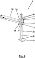
- a support arm 38 on the bearing base. 2 stored while the clamping device 1 is fixed in a certain amount on a vertically oriented support 39.
- This height is provided by a pair of a plurality of holes 40 on either side of the square cross-section support 39 to which the clamping elements 5 and 6 abut. In each case, a projection 25, 26 of the clamping elements 5 and 6 engages in one of the holes 40 of this pair.
- a support of the clamping device 1 is achieved on the vertically oriented support 39, which is then fixed by tightening the clamping screw assembly 7.
- a horizontally oriented mounting plate 41 for supporting the carrier 39, for example, by screwing to the bottom of a corner cabinet provided.
- a pair of lower holes 40 indicates the lowest meaningful position of the clamping device 1 with respect to the carrier 39.
- the upper holes 40 represent various useful positions of another clamping device 1 above the clamping device 1 in the deepest meaningful position.
- Fig. 5 shows in one Fig. 4 opposite perspective view direction that the second side of the support 39, to which the clamping elements 5 and 6 of the clamping device 1 also attack, no holes 40 has. Furthermore, it can be seen here that on the support arm 38, a tray 42 is mounted and that in the upper end of the carrier 39, an end piece 43 is telescopically inserted, which ends with a second horizontally oriented mounting plate 44. By telescoping the tail 43 in the carrier 39, the distance of the mounting plates 41 and 44 is adjustable. In this case, a set distance can be fixed by fixing the tail 43 to the support 39 by not visible here clamping means.
Landscapes
- Engineering & Computer Science (AREA)
- General Engineering & Computer Science (AREA)
- Mechanical Engineering (AREA)
- Clamps And Clips (AREA)
Priority Applications (1)
| Application Number | Priority Date | Filing Date | Title |
|---|---|---|---|
| EP17161619.6A EP3375328B1 (fr) | 2017-03-17 | 2017-03-17 | Dispositif de serrage destiné à fixer dans différentes positions longitudinales sur un support étiré |
Applications Claiming Priority (1)
| Application Number | Priority Date | Filing Date | Title |
|---|---|---|---|
| EP17161619.6A EP3375328B1 (fr) | 2017-03-17 | 2017-03-17 | Dispositif de serrage destiné à fixer dans différentes positions longitudinales sur un support étiré |
Publications (2)
| Publication Number | Publication Date |
|---|---|
| EP3375328A1 true EP3375328A1 (fr) | 2018-09-19 |
| EP3375328B1 EP3375328B1 (fr) | 2019-10-09 |
Family
ID=58387697
Family Applications (1)
| Application Number | Title | Priority Date | Filing Date |
|---|---|---|---|
| EP17161619.6A Active EP3375328B1 (fr) | 2017-03-17 | 2017-03-17 | Dispositif de serrage destiné à fixer dans différentes positions longitudinales sur un support étiré |
Country Status (1)
| Country | Link |
|---|---|
| EP (1) | EP3375328B1 (fr) |
Citations (3)
| Publication number | Priority date | Publication date | Assignee | Title |
|---|---|---|---|---|
| US5272952A (en) * | 1992-01-28 | 1993-12-28 | Hoshino Gakki Co., Ltd. | Hoop clamp for a bass drum |
| EP2965656A1 (fr) | 2014-07-07 | 2016-01-13 | Hetal-Werke Franz Hettich GmbH & Co. KG | Dispositif de montage pour un élément support sur une colonne porteuse |
| EP2353440B1 (fr) | 2010-02-05 | 2016-04-13 | Hetal-Werke Franz Hettich GmbH & Co. KG | Armature pour une armoire de coin et armoire de coin |
-
2017
- 2017-03-17 EP EP17161619.6A patent/EP3375328B1/fr active Active
Patent Citations (3)
| Publication number | Priority date | Publication date | Assignee | Title |
|---|---|---|---|---|
| US5272952A (en) * | 1992-01-28 | 1993-12-28 | Hoshino Gakki Co., Ltd. | Hoop clamp for a bass drum |
| EP2353440B1 (fr) | 2010-02-05 | 2016-04-13 | Hetal-Werke Franz Hettich GmbH & Co. KG | Armature pour une armoire de coin et armoire de coin |
| EP2965656A1 (fr) | 2014-07-07 | 2016-01-13 | Hetal-Werke Franz Hettich GmbH & Co. KG | Dispositif de montage pour un élément support sur une colonne porteuse |
Also Published As
| Publication number | Publication date |
|---|---|
| EP3375328B1 (fr) | 2019-10-09 |
Similar Documents
| Publication | Publication Date | Title |
|---|---|---|
| DE4333913C2 (de) | Einstellvorrichtung an längen- und/oder neigungsverstellbaren Haltern, insbesondere für Percussions-Musikinstrumente | |
| DE60128109T2 (de) | Vorrichtung zum fixieren von teleskopisch zusammenwirkenden elementen | |
| DE102011118538B4 (de) | Fixierung des Druckstempels einer Schnellspannvorrichtung | |
| DE102012218762A1 (de) | Vorrichtung zur sicherung von ladegut | |
| EP0868978A1 (fr) | Pince à sertir pour sertir une pièce | |
| EP2345507A2 (fr) | Dispositif de serrage de pièces usinées sur une base | |
| DE202009003633U1 (de) | Vorrichtung zur Befestigung von Balken und anderen Bauteilen | |
| EP3725379A1 (fr) | Fixation de tige | |
| DE2847006B1 (de) | AEussere Spannvorrichtung fuer chirurgische Zwecke | |
| DE3341402A1 (de) | Verriegelbares dreibeinstativ-bein | |
| EP0610878B1 (fr) | Armoire de coin, en particulier armoire de coin de cuisine, avec étagères rotatives | |
| DE2841588B2 (de) | Kerbzange zum Aufpressen von Kabelschuhen und Verbindern auf elektrische Leiter | |
| EP3375328B1 (fr) | Dispositif de serrage destiné à fixer dans différentes positions longitudinales sur un support étiré | |
| EP1888280B1 (fr) | Liaison entre deux parties d'outil | |
| DE19805833B4 (de) | Verbindungseinrichtung zum Verbinden zweier Körper | |
| DE102005047099B4 (de) | Chirurgisches Befestigungselement, Satz solcher Befestigungselemente, Zubehörteil und dazugehöriger Satz sowie Befestigungssystem und chirurgischer Behälter | |
| EP2965656A1 (fr) | Dispositif de montage pour un élément support sur une colonne porteuse | |
| DE29818831U1 (de) | Osteosynthetisches Haltesystem | |
| EP4190492A1 (fr) | Système d'adaptateur d'établi pour établis pourvus de grille perforée | |
| DE4012614C2 (de) | Verbindungselement zur Befestigung eines eine Platte aufnehmenden Tragteils an einer Stange | |
| DE19735331A1 (de) | Vorrichtung zur Aufnahme von Gegenständen | |
| DE29912232U1 (de) | Schraubwerkzeug | |
| DE20302476U1 (de) | Conga-Ständer | |
| EP2039263A1 (fr) | Table | |
| AT18486U1 (de) | Stapelspanneinrichtung zur Fixierung eines Werkstücks oder einer Werkstückhalterung an einer Grundplatte |
Legal Events
| Date | Code | Title | Description |
|---|---|---|---|
| PUAI | Public reference made under article 153(3) epc to a published international application that has entered the european phase |
Free format text: ORIGINAL CODE: 0009012 |
|
| STAA | Information on the status of an ep patent application or granted ep patent |
Free format text: STATUS: THE APPLICATION HAS BEEN PUBLISHED |
|
| AK | Designated contracting states |
Kind code of ref document: A1 Designated state(s): AL AT BE BG CH CY CZ DE DK EE ES FI FR GB GR HR HU IE IS IT LI LT LU LV MC MK MT NL NO PL PT RO RS SE SI SK SM TR |
|
| AX | Request for extension of the european patent |
Extension state: BA ME |
|
| STAA | Information on the status of an ep patent application or granted ep patent |
Free format text: STATUS: REQUEST FOR EXAMINATION WAS MADE |
|
| 17P | Request for examination filed |
Effective date: 20190318 |
|
| RBV | Designated contracting states (corrected) |
Designated state(s): AL AT BE BG CH CY CZ DE DK EE ES FI FR GB GR HR HU IE IS IT LI LT LU LV MC MK MT NL NO PL PT RO RS SE SI SK SM TR |
|
| GRAP | Despatch of communication of intention to grant a patent |
Free format text: ORIGINAL CODE: EPIDOSNIGR1 |
|
| STAA | Information on the status of an ep patent application or granted ep patent |
Free format text: STATUS: GRANT OF PATENT IS INTENDED |
|
| INTG | Intention to grant announced |
Effective date: 20190429 |
|
| GRAS | Grant fee paid |
Free format text: ORIGINAL CODE: EPIDOSNIGR3 |
|
| GRAA | (expected) grant |
Free format text: ORIGINAL CODE: 0009210 |
|
| STAA | Information on the status of an ep patent application or granted ep patent |
Free format text: STATUS: THE PATENT HAS BEEN GRANTED |
|
| AK | Designated contracting states |
Kind code of ref document: B1 Designated state(s): AL AT BE BG CH CY CZ DE DK EE ES FI FR GB GR HR HU IE IS IT LI LT LU LV MC MK MT NL NO PL PT RO RS SE SI SK SM TR |
|
| REG | Reference to a national code |
Ref country code: GB Ref legal event code: FG4D Free format text: NOT ENGLISH |
|
| REG | Reference to a national code |
Ref country code: CH Ref legal event code: EP |
|
| REG | Reference to a national code |
Ref country code: IE Ref legal event code: FG4D Free format text: LANGUAGE OF EP DOCUMENT: GERMAN |
|
| REG | Reference to a national code |
Ref country code: DE Ref legal event code: R096 Ref document number: 502017002485 Country of ref document: DE |
|
| REG | Reference to a national code |
Ref country code: AT Ref legal event code: REF Ref document number: 1187778 Country of ref document: AT Kind code of ref document: T Effective date: 20191115 |
|
| REG | Reference to a national code |
Ref country code: NL Ref legal event code: MP Effective date: 20191009 |
|
| REG | Reference to a national code |
Ref country code: LT Ref legal event code: MG4D |
|
| PG25 | Lapsed in a contracting state [announced via postgrant information from national office to epo] |
Ref country code: ES Free format text: LAPSE BECAUSE OF FAILURE TO SUBMIT A TRANSLATION OF THE DESCRIPTION OR TO PAY THE FEE WITHIN THE PRESCRIBED TIME-LIMIT Effective date: 20191009 Ref country code: PT Free format text: LAPSE BECAUSE OF FAILURE TO SUBMIT A TRANSLATION OF THE DESCRIPTION OR TO PAY THE FEE WITHIN THE PRESCRIBED TIME-LIMIT Effective date: 20200210 Ref country code: LV Free format text: LAPSE BECAUSE OF FAILURE TO SUBMIT A TRANSLATION OF THE DESCRIPTION OR TO PAY THE FEE WITHIN THE PRESCRIBED TIME-LIMIT Effective date: 20191009 Ref country code: SE Free format text: LAPSE BECAUSE OF FAILURE TO SUBMIT A TRANSLATION OF THE DESCRIPTION OR TO PAY THE FEE WITHIN THE PRESCRIBED TIME-LIMIT Effective date: 20191009 Ref country code: NL Free format text: LAPSE BECAUSE OF FAILURE TO SUBMIT A TRANSLATION OF THE DESCRIPTION OR TO PAY THE FEE WITHIN THE PRESCRIBED TIME-LIMIT Effective date: 20191009 Ref country code: PL Free format text: LAPSE BECAUSE OF FAILURE TO SUBMIT A TRANSLATION OF THE DESCRIPTION OR TO PAY THE FEE WITHIN THE PRESCRIBED TIME-LIMIT Effective date: 20191009 Ref country code: LT Free format text: LAPSE BECAUSE OF FAILURE TO SUBMIT A TRANSLATION OF THE DESCRIPTION OR TO PAY THE FEE WITHIN THE PRESCRIBED TIME-LIMIT Effective date: 20191009 Ref country code: FI Free format text: LAPSE BECAUSE OF FAILURE TO SUBMIT A TRANSLATION OF THE DESCRIPTION OR TO PAY THE FEE WITHIN THE PRESCRIBED TIME-LIMIT Effective date: 20191009 Ref country code: BG Free format text: LAPSE BECAUSE OF FAILURE TO SUBMIT A TRANSLATION OF THE DESCRIPTION OR TO PAY THE FEE WITHIN THE PRESCRIBED TIME-LIMIT Effective date: 20200109 Ref country code: NO Free format text: LAPSE BECAUSE OF FAILURE TO SUBMIT A TRANSLATION OF THE DESCRIPTION OR TO PAY THE FEE WITHIN THE PRESCRIBED TIME-LIMIT Effective date: 20200109 Ref country code: GR Free format text: LAPSE BECAUSE OF FAILURE TO SUBMIT A TRANSLATION OF THE DESCRIPTION OR TO PAY THE FEE WITHIN THE PRESCRIBED TIME-LIMIT Effective date: 20200110 |
|
| PG25 | Lapsed in a contracting state [announced via postgrant information from national office to epo] |
Ref country code: RS Free format text: LAPSE BECAUSE OF FAILURE TO SUBMIT A TRANSLATION OF THE DESCRIPTION OR TO PAY THE FEE WITHIN THE PRESCRIBED TIME-LIMIT Effective date: 20191009 Ref country code: IS Free format text: LAPSE BECAUSE OF FAILURE TO SUBMIT A TRANSLATION OF THE DESCRIPTION OR TO PAY THE FEE WITHIN THE PRESCRIBED TIME-LIMIT Effective date: 20200224 Ref country code: HR Free format text: LAPSE BECAUSE OF FAILURE TO SUBMIT A TRANSLATION OF THE DESCRIPTION OR TO PAY THE FEE WITHIN THE PRESCRIBED TIME-LIMIT Effective date: 20191009 |
|
| PG25 | Lapsed in a contracting state [announced via postgrant information from national office to epo] |
Ref country code: AL Free format text: LAPSE BECAUSE OF FAILURE TO SUBMIT A TRANSLATION OF THE DESCRIPTION OR TO PAY THE FEE WITHIN THE PRESCRIBED TIME-LIMIT Effective date: 20191009 |
|
| REG | Reference to a national code |
Ref country code: DE Ref legal event code: R097 Ref document number: 502017002485 Country of ref document: DE |
|
| PG2D | Information on lapse in contracting state deleted |
Ref country code: IS |
|
| PG25 | Lapsed in a contracting state [announced via postgrant information from national office to epo] |
Ref country code: DK Free format text: LAPSE BECAUSE OF FAILURE TO SUBMIT A TRANSLATION OF THE DESCRIPTION OR TO PAY THE FEE WITHIN THE PRESCRIBED TIME-LIMIT Effective date: 20191009 Ref country code: EE Free format text: LAPSE BECAUSE OF FAILURE TO SUBMIT A TRANSLATION OF THE DESCRIPTION OR TO PAY THE FEE WITHIN THE PRESCRIBED TIME-LIMIT Effective date: 20191009 Ref country code: RO Free format text: LAPSE BECAUSE OF FAILURE TO SUBMIT A TRANSLATION OF THE DESCRIPTION OR TO PAY THE FEE WITHIN THE PRESCRIBED TIME-LIMIT Effective date: 20191009 Ref country code: CZ Free format text: LAPSE BECAUSE OF FAILURE TO SUBMIT A TRANSLATION OF THE DESCRIPTION OR TO PAY THE FEE WITHIN THE PRESCRIBED TIME-LIMIT Effective date: 20191009 Ref country code: IS Free format text: LAPSE BECAUSE OF FAILURE TO SUBMIT A TRANSLATION OF THE DESCRIPTION OR TO PAY THE FEE WITHIN THE PRESCRIBED TIME-LIMIT Effective date: 20200209 |
|
| PLBE | No opposition filed within time limit |
Free format text: ORIGINAL CODE: 0009261 |
|
| STAA | Information on the status of an ep patent application or granted ep patent |
Free format text: STATUS: NO OPPOSITION FILED WITHIN TIME LIMIT |
|
| PG25 | Lapsed in a contracting state [announced via postgrant information from national office to epo] |
Ref country code: SK Free format text: LAPSE BECAUSE OF FAILURE TO SUBMIT A TRANSLATION OF THE DESCRIPTION OR TO PAY THE FEE WITHIN THE PRESCRIBED TIME-LIMIT Effective date: 20191009 Ref country code: IT Free format text: LAPSE BECAUSE OF FAILURE TO SUBMIT A TRANSLATION OF THE DESCRIPTION OR TO PAY THE FEE WITHIN THE PRESCRIBED TIME-LIMIT Effective date: 20191009 Ref country code: SM Free format text: LAPSE BECAUSE OF FAILURE TO SUBMIT A TRANSLATION OF THE DESCRIPTION OR TO PAY THE FEE WITHIN THE PRESCRIBED TIME-LIMIT Effective date: 20191009 |
|
| 26N | No opposition filed |
Effective date: 20200710 |
|
| PG25 | Lapsed in a contracting state [announced via postgrant information from national office to epo] |
Ref country code: MC Free format text: LAPSE BECAUSE OF FAILURE TO SUBMIT A TRANSLATION OF THE DESCRIPTION OR TO PAY THE FEE WITHIN THE PRESCRIBED TIME-LIMIT Effective date: 20191009 |
|
| REG | Reference to a national code |
Ref country code: CH Ref legal event code: PL |
|
| PG25 | Lapsed in a contracting state [announced via postgrant information from national office to epo] |
Ref country code: SI Free format text: LAPSE BECAUSE OF FAILURE TO SUBMIT A TRANSLATION OF THE DESCRIPTION OR TO PAY THE FEE WITHIN THE PRESCRIBED TIME-LIMIT Effective date: 20191009 |
|
| REG | Reference to a national code |
Ref country code: BE Ref legal event code: MM Effective date: 20200331 |
|
| PG25 | Lapsed in a contracting state [announced via postgrant information from national office to epo] |
Ref country code: LU Free format text: LAPSE BECAUSE OF NON-PAYMENT OF DUE FEES Effective date: 20200317 |
|
| PG25 | Lapsed in a contracting state [announced via postgrant information from national office to epo] |
Ref country code: FR Free format text: LAPSE BECAUSE OF NON-PAYMENT OF DUE FEES Effective date: 20200331 Ref country code: IE Free format text: LAPSE BECAUSE OF NON-PAYMENT OF DUE FEES Effective date: 20200317 Ref country code: CH Free format text: LAPSE BECAUSE OF NON-PAYMENT OF DUE FEES Effective date: 20200331 Ref country code: LI Free format text: LAPSE BECAUSE OF NON-PAYMENT OF DUE FEES Effective date: 20200331 |
|
| PG25 | Lapsed in a contracting state [announced via postgrant information from national office to epo] |
Ref country code: BE Free format text: LAPSE BECAUSE OF NON-PAYMENT OF DUE FEES Effective date: 20200331 |
|
| GBPC | Gb: european patent ceased through non-payment of renewal fee |
Effective date: 20210317 |
|
| PG25 | Lapsed in a contracting state [announced via postgrant information from national office to epo] |
Ref country code: GB Free format text: LAPSE BECAUSE OF NON-PAYMENT OF DUE FEES Effective date: 20210317 |
|
| PG25 | Lapsed in a contracting state [announced via postgrant information from national office to epo] |
Ref country code: TR Free format text: LAPSE BECAUSE OF FAILURE TO SUBMIT A TRANSLATION OF THE DESCRIPTION OR TO PAY THE FEE WITHIN THE PRESCRIBED TIME-LIMIT Effective date: 20191009 Ref country code: MT Free format text: LAPSE BECAUSE OF FAILURE TO SUBMIT A TRANSLATION OF THE DESCRIPTION OR TO PAY THE FEE WITHIN THE PRESCRIBED TIME-LIMIT Effective date: 20191009 Ref country code: CY Free format text: LAPSE BECAUSE OF FAILURE TO SUBMIT A TRANSLATION OF THE DESCRIPTION OR TO PAY THE FEE WITHIN THE PRESCRIBED TIME-LIMIT Effective date: 20191009 |
|
| PG25 | Lapsed in a contracting state [announced via postgrant information from national office to epo] |
Ref country code: MK Free format text: LAPSE BECAUSE OF FAILURE TO SUBMIT A TRANSLATION OF THE DESCRIPTION OR TO PAY THE FEE WITHIN THE PRESCRIBED TIME-LIMIT Effective date: 20191009 |
|
| REG | Reference to a national code |
Ref country code: AT Ref legal event code: MM01 Ref document number: 1187778 Country of ref document: AT Kind code of ref document: T Effective date: 20220317 |
|
| P01 | Opt-out of the competence of the unified patent court (upc) registered |
Effective date: 20230528 |
|
| PG25 | Lapsed in a contracting state [announced via postgrant information from national office to epo] |
Ref country code: AT Free format text: LAPSE BECAUSE OF NON-PAYMENT OF DUE FEES Effective date: 20220317 |
|
| PGFP | Annual fee paid to national office [announced via postgrant information from national office to epo] |
Ref country code: DE Payment date: 20260210 Year of fee payment: 10 |