EP3375392B1 - Systèmes de stabilisation d'os - Google Patents
Systèmes de stabilisation d'os Download PDFInfo
- Publication number
- EP3375392B1 EP3375392B1 EP18161322.5A EP18161322A EP3375392B1 EP 3375392 B1 EP3375392 B1 EP 3375392B1 EP 18161322 A EP18161322 A EP 18161322A EP 3375392 B1 EP3375392 B1 EP 3375392B1
- Authority
- EP
- European Patent Office
- Prior art keywords
- holes
- bone plate
- bone
- rafting
- locking
- Prior art date
- Legal status (The legal status is an assumption and is not a legal conclusion. Google has not performed a legal analysis and makes no representation as to the accuracy of the status listed.)
- Active
Links
Images










Classifications
-
- A—HUMAN NECESSITIES
- A61—MEDICAL OR VETERINARY SCIENCE; HYGIENE
- A61B—DIAGNOSIS; SURGERY; IDENTIFICATION
- A61B17/00—Surgical instruments, devices or methods
- A61B17/56—Surgical instruments or methods for treatment of bones or joints; Devices specially adapted therefor
- A61B17/58—Surgical instruments or methods for treatment of bones or joints; Devices specially adapted therefor for osteosynthesis, e.g. bone plates, screws or setting implements
- A61B17/68—Internal fixation devices, including fasteners and spinal fixators, even if a part thereof projects from the skin
- A61B17/80—Cortical plates, i.e. bone plates; Instruments for holding or positioning cortical plates, or for compressing bones attached to cortical plates
- A61B17/8004—Cortical plates, i.e. bone plates; Instruments for holding or positioning cortical plates, or for compressing bones attached to cortical plates with means for distracting or compressing the bone or bones
- A61B17/8014—Cortical plates, i.e. bone plates; Instruments for holding or positioning cortical plates, or for compressing bones attached to cortical plates with means for distracting or compressing the bone or bones the extension or compression force being caused by interaction of the plate hole and the screws
-
- A—HUMAN NECESSITIES
- A61—MEDICAL OR VETERINARY SCIENCE; HYGIENE
- A61B—DIAGNOSIS; SURGERY; IDENTIFICATION
- A61B17/00—Surgical instruments, devices or methods
- A61B17/16—Instruments for performing osteoclasis; Drills or chisels for bones; Trepans
- A61B17/17—Guides or aligning means for drills, mills, pins or wires
- A61B17/1728—Guides or aligning means for drills, mills, pins or wires for holes for bone plates or plate screws
-
- A—HUMAN NECESSITIES
- A61—MEDICAL OR VETERINARY SCIENCE; HYGIENE
- A61B—DIAGNOSIS; SURGERY; IDENTIFICATION
- A61B17/00—Surgical instruments, devices or methods
- A61B17/56—Surgical instruments or methods for treatment of bones or joints; Devices specially adapted therefor
- A61B17/58—Surgical instruments or methods for treatment of bones or joints; Devices specially adapted therefor for osteosynthesis, e.g. bone plates, screws or setting implements
- A61B17/68—Internal fixation devices, including fasteners and spinal fixators, even if a part thereof projects from the skin
- A61B17/80—Cortical plates, i.e. bone plates; Instruments for holding or positioning cortical plates, or for compressing bones attached to cortical plates
- A61B17/8004—Cortical plates, i.e. bone plates; Instruments for holding or positioning cortical plates, or for compressing bones attached to cortical plates with means for distracting or compressing the bone or bones
-
- A—HUMAN NECESSITIES
- A61—MEDICAL OR VETERINARY SCIENCE; HYGIENE
- A61B—DIAGNOSIS; SURGERY; IDENTIFICATION
- A61B17/00—Surgical instruments, devices or methods
- A61B17/56—Surgical instruments or methods for treatment of bones or joints; Devices specially adapted therefor
- A61B17/58—Surgical instruments or methods for treatment of bones or joints; Devices specially adapted therefor for osteosynthesis, e.g. bone plates, screws or setting implements
- A61B17/68—Internal fixation devices, including fasteners and spinal fixators, even if a part thereof projects from the skin
- A61B17/80—Cortical plates, i.e. bone plates; Instruments for holding or positioning cortical plates, or for compressing bones attached to cortical plates
- A61B17/8033—Cortical plates, i.e. bone plates; Instruments for holding or positioning cortical plates, or for compressing bones attached to cortical plates having indirect contact with screw heads, or having contact with screw heads maintained with the aid of additional components, e.g. nuts, wedges or head covers
-
- A—HUMAN NECESSITIES
- A61—MEDICAL OR VETERINARY SCIENCE; HYGIENE
- A61B—DIAGNOSIS; SURGERY; IDENTIFICATION
- A61B17/00—Surgical instruments, devices or methods
- A61B17/56—Surgical instruments or methods for treatment of bones or joints; Devices specially adapted therefor
- A61B17/58—Surgical instruments or methods for treatment of bones or joints; Devices specially adapted therefor for osteosynthesis, e.g. bone plates, screws or setting implements
- A61B17/68—Internal fixation devices, including fasteners and spinal fixators, even if a part thereof projects from the skin
- A61B17/80—Cortical plates, i.e. bone plates; Instruments for holding or positioning cortical plates, or for compressing bones attached to cortical plates
- A61B17/8052—Cortical plates, i.e. bone plates; Instruments for holding or positioning cortical plates, or for compressing bones attached to cortical plates immobilised relative to screws by interlocking form of the heads and plate holes, e.g. conical or threaded
-
- A—HUMAN NECESSITIES
- A61—MEDICAL OR VETERINARY SCIENCE; HYGIENE
- A61B—DIAGNOSIS; SURGERY; IDENTIFICATION
- A61B17/00—Surgical instruments, devices or methods
- A61B17/56—Surgical instruments or methods for treatment of bones or joints; Devices specially adapted therefor
- A61B17/58—Surgical instruments or methods for treatment of bones or joints; Devices specially adapted therefor for osteosynthesis, e.g. bone plates, screws or setting implements
- A61B17/68—Internal fixation devices, including fasteners and spinal fixators, even if a part thereof projects from the skin
- A61B17/80—Cortical plates, i.e. bone plates; Instruments for holding or positioning cortical plates, or for compressing bones attached to cortical plates
- A61B17/8052—Cortical plates, i.e. bone plates; Instruments for holding or positioning cortical plates, or for compressing bones attached to cortical plates immobilised relative to screws by interlocking form of the heads and plate holes, e.g. conical or threaded
- A61B17/8057—Cortical plates, i.e. bone plates; Instruments for holding or positioning cortical plates, or for compressing bones attached to cortical plates immobilised relative to screws by interlocking form of the heads and plate holes, e.g. conical or threaded the interlocking form comprising a thread
-
- A—HUMAN NECESSITIES
- A61—MEDICAL OR VETERINARY SCIENCE; HYGIENE
- A61B—DIAGNOSIS; SURGERY; IDENTIFICATION
- A61B17/00—Surgical instruments, devices or methods
- A61B17/56—Surgical instruments or methods for treatment of bones or joints; Devices specially adapted therefor
- A61B17/58—Surgical instruments or methods for treatment of bones or joints; Devices specially adapted therefor for osteosynthesis, e.g. bone plates, screws or setting implements
- A61B17/68—Internal fixation devices, including fasteners and spinal fixators, even if a part thereof projects from the skin
- A61B17/80—Cortical plates, i.e. bone plates; Instruments for holding or positioning cortical plates, or for compressing bones attached to cortical plates
- A61B17/8061—Cortical plates, i.e. bone plates; Instruments for holding or positioning cortical plates, or for compressing bones attached to cortical plates specially adapted for particular bones
-
- A—HUMAN NECESSITIES
- A61—MEDICAL OR VETERINARY SCIENCE; HYGIENE
- A61B—DIAGNOSIS; SURGERY; IDENTIFICATION
- A61B17/00—Surgical instruments, devices or methods
- A61B17/56—Surgical instruments or methods for treatment of bones or joints; Devices specially adapted therefor
- A61B17/58—Surgical instruments or methods for treatment of bones or joints; Devices specially adapted therefor for osteosynthesis, e.g. bone plates, screws or setting implements
- A61B17/68—Internal fixation devices, including fasteners and spinal fixators, even if a part thereof projects from the skin
- A61B17/80—Cortical plates, i.e. bone plates; Instruments for holding or positioning cortical plates, or for compressing bones attached to cortical plates
- A61B17/809—Cortical plates, i.e. bone plates; Instruments for holding or positioning cortical plates, or for compressing bones attached to cortical plates with bone-penetrating elements, e.g. blades or prongs
-
- A—HUMAN NECESSITIES
- A61—MEDICAL OR VETERINARY SCIENCE; HYGIENE
- A61B—DIAGNOSIS; SURGERY; IDENTIFICATION
- A61B17/00—Surgical instruments, devices or methods
- A61B17/56—Surgical instruments or methods for treatment of bones or joints; Devices specially adapted therefor
- A61B17/58—Surgical instruments or methods for treatment of bones or joints; Devices specially adapted therefor for osteosynthesis, e.g. bone plates, screws or setting implements
- A61B17/68—Internal fixation devices, including fasteners and spinal fixators, even if a part thereof projects from the skin
- A61B17/74—Devices for the head or neck or trochanter of the femur
-
- A—HUMAN NECESSITIES
- A61—MEDICAL OR VETERINARY SCIENCE; HYGIENE
- A61B—DIAGNOSIS; SURGERY; IDENTIFICATION
- A61B17/00—Surgical instruments, devices or methods
- A61B17/56—Surgical instruments or methods for treatment of bones or joints; Devices specially adapted therefor
- A61B17/58—Surgical instruments or methods for treatment of bones or joints; Devices specially adapted therefor for osteosynthesis, e.g. bone plates, screws or setting implements
- A61B17/68—Internal fixation devices, including fasteners and spinal fixators, even if a part thereof projects from the skin
- A61B17/80—Cortical plates, i.e. bone plates; Instruments for holding or positioning cortical plates, or for compressing bones attached to cortical plates
- A61B17/808—Instruments for holding or positioning bone plates, or for adjusting screw-to-plate locking mechanisms
-
- A—HUMAN NECESSITIES
- A61—MEDICAL OR VETERINARY SCIENCE; HYGIENE
- A61B—DIAGNOSIS; SURGERY; IDENTIFICATION
- A61B17/00—Surgical instruments, devices or methods
- A61B17/56—Surgical instruments or methods for treatment of bones or joints; Devices specially adapted therefor
- A61B17/58—Surgical instruments or methods for treatment of bones or joints; Devices specially adapted therefor for osteosynthesis, e.g. bone plates, screws or setting implements
- A61B17/68—Internal fixation devices, including fasteners and spinal fixators, even if a part thereof projects from the skin
- A61B17/84—Fasteners therefor or fasteners being internal fixation devices
- A61B17/86—Pins or screws or threaded wires; nuts therefor
Definitions
- the present disclosure relates to surgical devices, and more particularly, stabilization systems including plates, for example, for trauma applications.
- Bone fractures can be healed using plating systems. During treatment, one or more screws are placed on either side of a fracture, thereby causing compression and healing of the fracture. There is a need for improved plating systems as well as mechanisms for accurate use of the plating systems.
- US 2015/0313654 describes a bone plate configured for pancarpal arthrodesis.
- a system for treating a fracture in a bone comprises: a bone plate configured to engage the bone, the bone plate comprising a proximal end, a distal end, a head portion, a neck portion and a shaft portion, wherein the head portion comprises a first row of holes and a second row of holes for receiving one or more fasteners therein, wherein the shaft portion comprises at least one additional hole for receiving a fastener therein; at least one fastener received in the head portion and positioned in the first row of holes or second row of holes; and at least one fastener received in the shaft portion and positioned in the at least one additional hole.
- the system comprises: a bone plate configured to engage the bone, the bone plate comprising a proximal end, a distal end, a head portion, a neck portion and a shaft portion, wherein the head portion comprises a first row of holes and a second row of holes for receiving one or more fasteners therein, wherein the shaft portion comprises at least one additional hole for receiving a fastener therein; at least one fastener received in the head portion and positioned in the first row of holes or second row of holes, wherein the at least one fastener is non-threaded; and at least one fastener received in the shaft portion and positioned in the at least one additional hole.
- a system for treating a fracture in a bone comprising: a bone plate configured to engage the bone, the bone plate comprising a proximal end, a distal end, a head portion, a neck portion and a shaft portion, wherein the head portion comprises a first row of holes and a second row of holes for receiving one or more fasteners therein, wherein the shaft portion comprises at least one additional hole for receiving a fastener therein; at least one fastener received in the head portion and positioned in the first row of holes or second row of holes, wherein the at least one fastener is non-threaded; and at least one fastener received in the shaft portion and positioned in the at least one additional hole.
- the system further comprises an aiming guide for assisting in the insertion of one or more fasteners into the bone plate.
- the system further comprises the aiming guide comprises a distal aiming guide capable of attachment to a proximal aiming guide.
- the proximal aiming guide comprises a rotatable dial.
- the head portion comprises at least one multi-functional hole capable of receiving a k-wire or suture therein.
- the at least one multi-functional hole is positioned adjacent to an undercut in the bone plate.
- the first row of holes is comprised of holes that are smaller than holes in the second row of holes.
- the shaft portion comprises a pair of holes for receiving a fastener therein, wherein the pair of holes comprises a stacked hole adjacent a compression slot.
- the shaft portion comprises a scalloped contact surface.
- the at least one fastener received in the shaft portion is threaded.
- Embodiments of the present application are generally directed to a system for bone stabilization.
- embodiments are directed to bone plates that extend across bone members to treat one or more fractures.
- the plates described herein may be adapted to contact one or more of a femur, a distal tibia, a proximal tibia, a proximal humerus, a distal humerus, a clavicle, a fibula, an ulna, a radius, bones of the foot, bones of the hand, or other suitable bone or bones.
- the bone plates may be curved, contoured, straight, or flat.
- the plates may have a head portion that is contoured to match a particular bone surface, such as a metaphysis or diaphysis, flares out from the shaft portion, forms an L-shape, T-shape, Y-shape, etc., with the shaft portion, or that forms any other appropriate shape to fit the anatomy of the bone to be treated.
- the plates may be adapted to secure small or large bone fragments, single or multiple bone fragments, or otherwise secure one or more fractures.
- the systems may include a series of trauma plates and screws designed for the fixation of fractures and fragments in diaphyseal and metaphyseal bone. Different bone plates may be used to treat various types and locations of fractures.
- the bone plates may be comprised of titanium, stainless steel, cobalt chrome, carbon composite, plastic or polymer-such as polyetheretherketone (PEEK), polyethylene, ultra high molecular weight polyethylene (UHMWPE), resorbable polylactic acid (PLA), polyglycolic acid (PGA), combinations or alloys of such materials or any other appropriate material that has sufficient strength to be secured to and hold bone, while also having sufficient biocompatibility to be implanted into a body.
- the bone plates may receive one or more screws or fasteners may be comprised of titanium, cobalt chrome, cobalt-chrome-molybdenum, stainless steel, tungsten carbide, combinations or alloys of such materials or other appropriate biocompatible materials.
- Locking plates include one or more openings for accepting one or more locking fasteners.
- the one or more openings can be partially or fully threaded. In some embodiments, these openings include fully threaded or stacked openings, which accept both locking and non-locking fasteners.
- the locking fasteners include heads that are at least partially threaded.
- the locking fasteners can be monoaxial or polyaxial.
- One non-limiting example of a locking fastener (among others) is shown in FIG. 6 of U.S. 15/405,368, filed January 13, 2017 .
- Non-locking plates include one or more openings for accepting one or more non-locking fasteners.
- the one or more openings at least in part be non-threaded.
- these openings include non-threaded or stacked openings, which accept both locking and non-locking fasteners.
- the non-locking fasteners include heads that are non-threaded.
- the non-locking fasteners can be monoaxial or polyaxial.
- One non-limiting example of a non-locking fastener (among others) is shown in FIG. 4 of U.S. 15/405,368, filed January 13, 2017 .
- the non-locking fasteners can include dynamic compression screws, which enable dynamic compression of an underlying bone.
- locking plates may be thicker than non-locking plates. Locking plates may be useful for patients that have weaker bone, while non-locking plates may be useful for patients that have strong bone.
- the locking and non-locking plates described below can be attached to different bones to treat fractures.
- the locking and non-locking plates can be used to treat fractures of the tibia, though one skilled in the art will appreciate that the novel plates described herein can be applied to fractures on other types of bone as well.
- the locking and non-locking plates can be considered to be lateral, medial or posteromedial plates.
- the plates can be attached to a lateral, medial or posteromedial aspect of a tibia.
- the plates are not limited to their specific locations on the tibia, and that a surgeon may choose to apply a lateral plate medially or a medial plate laterally, if desired.
- the bone plates shown in FIGS. 1 and 7-10 can be viewed as lateral plates, while the bone plates shown in FIGS. 11-17 can be viewed as medial or posteromedial plates.
- FIG. 1 is a top perspective view of a bone plate in accordance with some embodiments.
- the bone plate 10 comprises a lateral locking plate, wherein at least some of the fasteners received therein are locking fasteners.
- the bone plate 10 comprises a proximal end 12 and a distal end 14.
- the bone plate 10 further comprises a head portion 22, a shaft portion 26, and a transitionary neck portion 24 between the head portion 22 and the shaft portion 26.
- the head portion 22 comprises a widest portion of the bone plate 10 and is adjacent the proximal end 12.
- the proximal end 12 is chamfered.
- the proximal end 12 contour and chamfer helps to position the bone plate 10 posterior to Gerdy's tubercle to minimize soft tissue irritation in a highly affected area.
- the head portion 22 will be placed on a bone member (e.g., tibia) near an articular surface. Certain features of the head portion 22 are advantageously designed to prevent or resist subsidence of an articular surface.
- the head portion 22 comprises a first row of holes 32 and a second row of holes 34.
- these holes 32, 34 are considered to be "rafting" holes that can receive rafting screws (e.g., as shown in FIG. 30 ) that advantageously support an articular surface of a joint and prevent subsidence.
- the holes 32, 34 are locking holes that are at least partially threaded and designed to receive one or more polyaxial locking screws.
- the head portion 22 comprises a first row of holes 32 and a second row of holes 34, wherein the second row of holes 34 are larger than the first row of holes 32.
- the first row of holes 32 can be between 2.0 and 3.0 mm (e.g., 2.5 mm), while the second row of holes 34 can be between 3.0 and 4.0 mm (e.g., 3.5 mm).
- the bone plate 10 advantageously accommodates a greater number of rafting screws, thereby providing greater support near a joint.
- the most proximal set of holes 32 are especially novel and advantageous, as they are designed to be adjacent the proximal end 12 of the bone plate 10.
- holes 32 receive rafting screws that are closest to an articular surface of a joint. These holes 32 are smaller in size than holes 34, such that they can accommodate smaller rafting screws, which may be particularly hard to position in the limited space adjacent the articular surface.
- the first row of holes 32 are offset from the second row of holes 34, while in other embodiments, the first row of holes 32 are aligned with the second row of holes 34.
- the bone plate 10 includes four holes 32 and four holes 34.
- the head portion 22 further comprises one or more novel multi-purpose holes 36.
- the multi-purpose holes 36 are advantageously designed to accommodate a k-wire as well as a suture.
- the holes 36 are sized and positioned to receive a k-wire therein, thereby assisting in placement of the bone plate 10 on a bone member.
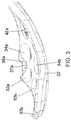
- the holes 36 are formed adjacent and continuously with one or more undercuts 37 (shown in FIGS. 2B and 3 ) of the bone plate 10.
- the one or more undercuts 37 advantageously allow access to one or more sutures through the bone plate 10 even after the bone plate 10 is implanted on bone.
- the sutures can be used to attach the bone plate 10 to adjacent tissue, thereby further securing the bone plate 10 at or near a surgical site.
- the neck portion 24 is a transitionary portion between the head portion 22 and the shaft portion 26.
- the neck portion 24 is less wide than the head portion 22, but has at least some portions that of equal or greater width than the shaft portion 26.
- the neck portion 24 comprises a pair of locking holes 42, an instrument attachment hole 44, alignment indentations 44, a positioning slot, and three kickstand holes 52. Each of these features is described below.
- the pair of locking holes 42 are positioned beneath the rafting holes 32, 34.
- the locking holes 42 comprise polyaxial locking holes that are at least partially threaded.
- the pair of locking holes 42 are configured to receive one or more bone fasteners or screws to secure the bone plate 10 to an underlying bone member.
- the pair of locking holes 42 are the same or similar width to the holes 34.
- each of the locking holes 42 has a width between 3.0 and 4.0 mm (e.g., 3.5 mm).
- the indentations 46 and instrument attachment hole 44 are designed to cooperate with an aiming guide, as shown in FIGS. 18 and 21 .
- the aiming guide is particularly useful with lateral plates, and can be used to accurately guide one or more bone screws or fasteners into respective holes in a bone plate 10.
- the indentations 46 comprise spherical indentations. Unlike other holes or openings in the bone plate 10, the indentations 46 do not extend completely through a plate. Rather, the indentations 46 are engaged by one or more ball-end pins (shown in FIG. 22 ) that extend outwardly from an attachment post of an aiming guide.
- the indentations 46 advantageously help to stabilize and position the aiming guide relative to the bone plate 10. While the bone plate 10 is shown as having three indentations 46, the bone plate 10 can include two, or more than three indentations 46. Between the indentations 46 is an instrument attachment hole 44.
- the instrument attachment hole 44 comprises a threaded hole that is designed to receive a threaded shaft (shown in FIG. 22 ) that also extends outwardly from an attachment post of an aiming guide. Once the aiming guide is stabilized via the indentations 46, the aiming guide can be attached to the bone plate 10 via threading of the threaded shaft.
- a positioning slot 48 is located distally and beneath the indentations 46 and instrument attachment hole 44.
- the positioning slot 48 comprises an elongated opening that is designed to receive a first bone screw or fastener therein before finalizing a position of a bone plate 10 on bone.
- the bone plate 10 can be slightly adjusted around a first bone fastener is needed.
- the positioning slot 48 has a length that is greater than a length of any of the other holes that receive bone screws therein.
- the positioning slot 48 has a length that is at least twice the length of a length of any of the other holes that receive bone screws therein.
- the first bone fastener can be provisionally placed in the positioning slot 48 prior to final tightening of the first bone screw. Upon proper orientation and placement of the bone plate 10, the first bone fastener can be finally tightened.
- One or more kickstand holes 62 are provided distally from the positioning slot 48.
- lateral plates may be preferred over medial plates, as they can often be implanted via a smaller incision with less risk to surrounding tissue.
- the one or more kickstand holes 62 are capable of receiving one or more bone fasteners that can treat medial fractures if desired.
- the kickstand holes 62 advantageously allow a medial fracture to be treated via support from just the lateral side.
- the bone plate 10 includes at least three kickstand holes 62.
- the kickstand holes 62 are fixed angle, stacked locking holes.
- the triple kickstand construct serves as a novel collection of kickstand holes 62 aimed at the anterior, middle, and posterior aspects of the medial proximal tibia, thereby providing the surgeon with options and enhanced versatility.
- the triple kickstand construct advantageously provides a surgeon with options for which fragments to target and allows the surgeon to customize construct rigidity with one or more screws or fasteners.
- the kickstand construct will have a single kickstand hole, two kickstand holes, or more than three kickstand holes.
- the shaft portion 26 comprises a distal portion of the bone plate 10 relative to the head portion 22 and neck portion 24. In some embodiments, the shaft portion 26 comprises a longest and narrowest portion of the bone plate 10.
- the shaft portion 26 comprises a number of openings or holes therein for receiving one or more bone fasteners.
- the shaft portion 26 comprises a plurality of holes 62 (e.g., five) that serve as fixed angled, stacked locking holes. These fixed angle, stacked locking holes allow mono-axial insertion of bone fasteners that can be locking or non-locking.
- the shaft portion 26 of the bone plate 10 also comprises a bi-direction, dynamic compression slot 64 that is positioned in between the locking holes 62.
- the bi-directional dynamic compression slot 64 advantageously allows for static insertion of non-locking screws into the shaft of bone. They also allow for compression (e.g., .5 mm - 2 mm) along the shaft of the bone through eccentric insertion of a non-locking screw.
- the holes 62 and slot 64 are capable of receiving one or more screws therein to secure the bone plate 10 to bone.
- the distal portion of the shaft portion 26 further comprises a tapered tip 18.
- the tapered tip 18 serves as an insertion tip that allows the plate 10 to be inserted beneath skin to a surgical site.
- the bone plate 10 can be positioned adjacent to bone (e.g., a tibia), whereby it can be fixed to the bone.
- the tapered tip allows for simplified submuscular plate insertion to minimize incision length.
- an underside of the shaft portion 26 of the bone plate 10 comprises a plurality of scallops 66.
- the scallops 66 form a scalloped contact surface which provides better frictional contact with a bone member.
- the scalloped contact surface minimizes impact to the periosteal blood supply and allows some bending of the shaft portion 26 of the bone plate 10 without deforming threaded holes.
- the bone plate 10 provides an anatomic contour that accommodates a lateral aspect of the proximal tibia.
- the bone plate 10 includes a proximal anterior portion (e.g., chamfered portion) that sits just posterior to Gerdy's tubercle, thereby assisting with positioning while minimizing soft tissue irritation.
- FIG. 2A is a top view of a head of the bone plate of FIG. 1 .
- the head portion 22 comprises a widest most portion of the bone plate 10.
- the head portion 22 accommodates a first row of holes 32a, 32b, 32c, 32d and a second row of holes 34a, 34b, 34c, 34d.
- the first row holes of holes and second row of holes can serve as "rafting" holes to accommodate rafting screws therein.
- the first row of holes 32 are smaller than the second row of holes 34.
- the first row of holes 32 are offset from the second row of holes 34. As shown in FIG.
- a pair of novel multi-purpose holes 36a, 36b are also provided through the head portion 22 of the bone plate 10.
- the multi-purpose holes 36a, 36b are each configured to receive a k-wire and/or suture therethrough.
- FIG. 2B is a bottom view of a head of the bone plate of FIG. 1 . From the bottom view, one can see the underside of the head portion 22 of the bone plate 10. In particular, one can see the underside of the multi-purpose holes 36a, 36b and how they are formed adjacent and continuously with undercuts 37a, 37b formed on the bone plate 10. As shown in FIG. 5 , the undercuts 37a, 37b advantageously allow a suture to be threaded between a bone plate 10 and an underlying bone 2, even when the bone plate 10 is positioned adjacent the bone 2. As shown in FIG. 2B , the undercuts 37a, 37b surround the perimeters of each of the multi-purpose holes 36a, 36b.
- FIG. 3 is a side perspective view of a head of the bone plate of FIG. 1 . From this view, one can see the curved angle of the head portion 22 of the bone plate 10. In addition, one can see how the undercuts 37a, 37b follow the curved contour of the bone plate 10 and are curved themselves.
- FIG. 4 is a view of the bone plate of FIG. 1 attached to a bone.
- the bone plate 10 includes a plurality of screws or fasteners 6 received therein. Screws 6 that are received in the holes 32a, 32b, 32c, 32d, as well as in the holes 34a, 34b, 34c, 34d, can be considered rafting screws.
- the rafting screws are positioned close to an articular surface 4 of the bone 2 (e.g., tibia) and advantageously help to provide support for the articular surface 4. In other words, the rafting screws help to serve as rebar for the articular surface 4. From this view, one can also see a suture undercut 37a that is formed at a corner of the bone plate 10.
- FIG. 5 is an alternative view of the bone plate of FIG. 1 attached to a bone. From this view, one can see how the undercut 37 forms an opening between the bone plate 10 and bone 2 such that there is access to thread a suture even when the bone plate 10 is implanted on bone 2.
- FIG. 6 is a top view of a shaft of the bone plate of FIG. 1 with a cross-sectional view shown beneath.
- the shaft portion 26 includes a number of holes or openings for receiving different bone screws (e.g., locking or non-locking) therein.
- the shaft portion 26 can vary in length to accommodate different bones in different sized patients.
- each of the vertical perforated lines represents a possible cutoff or end of a bone plate 10. For patients with smaller bones, the cut-off could be sooner, while for patients with larger bones, the cut-off could be later.
- the shaft portion 26 accommodates a unique hole or opening pattern whereby the hole immediate preceding a plate end will be a fixed angle, stacked hole 62.
- the bone plate 10 can accommodate either a locking or a non-locking screw, thereby providing a large number of options for a surgeon implanting the plate.
- the novel pattern of holes or openings in the shaft portion 26 includes holes that are spaced apart (e.g., 12-14 mm) center-to-center and allows plate lengths to be offered in two-hole increments while maintaining that the last hole will always be a stacked hole.
- bi-directional compression slots 64 can be worked into the hole pattern, but can appear less than the stacked holes 62 as they may be used less frequently.
- the unique hole pattern maximizes equidistant locking and non-locking options in the shaft portion 26 while still providing dynamic compression capabilities.
- the last hole before the plate end allowing a statically placed locking or non-locking screw is preserved in all two-hole plate increments, as shown in FIG. 6 .
- FIG. 7 is a top perspective view of an alternative bone plate in accordance with some embodiments.
- the bone plate 10 comprises a lateral non-locking plate wherein at least some of holes or openings therein receive non-locking fasteners.
- the bone plate 10 includes similar features to the bone plate in FIG. 1 , including a proximal end 12 and a distal end 14, a head portion 22, a neck portion 24 and a shaft portion 26.
- the head portion 22 accommodates different sized rafting screws via a first row of rafting holes 32 and a second row of rafting holes 34.
- the head portion 22 also includes multi-purpose holes 34 capable of receiving a k-wire and/or suture therein.
- the bone plate 10 can include additional non-locking holes for receiving non-locking fasteners, as will be discussed in greater detail herein.
- the neck portion 24 can comprise holes 42 beneath the rafting holes.
- the holes 42 comprise a trio of non-locking holes capable of receiving non-locking fasteners therein. Beneath the holes 42 comprises an elongated positioning slot 48 for receiving a first bone screw, as discussed above.
- the shaft portion 26 comprises a number of non-locking holes.
- Shaft portion 26 comprises a non-locking hole 62 for receiving a non-locking fastener.
- shaft portion 26 comprises a series of bi-directional dynamic compression slots 64 (which can also be viewed as non-locking openings) for receiving one or more bone fasteners therein.
- the distal end 14 of the bone plate 10 comprises a tapered tip 18 that aids in insertion of the bone plate 10.
- An underside of the shaft portion 26 comprises a plurality of scallops 66.
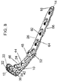
- FIG. 8 is a top perspective view of an alternative bone plate in accordance with some embodiments.
- the bone plate 10 comprises a lateral plate 10 having one or more locking holes for receiving locking fasteners.
- the thickness of the lateral bone plate 10 varies from 2.2 mm proximally to 3.4 mm distally, with the thickness transition occurring in the neck of the bone plate 10.
- the bone plate 10 includes many features as the bone plate in FIG. 1 , including a proximal end 12, a distal end 14, a head portion 22, a neck portion 24, and a shaft portion 26.
- the head portion 22 is the widest portion of the bone plate 10 and includes a pair of rows of rafting holes 32, 34, as well as a pair of multi-functional holes 36 for receiving a k-wire and/or suture therein.
- the neck portion 24 is also similar to that of the bone plate in FIG. 1 , as it includes a pair of polyaxial locking holes 42, a trio of spherical alignment indentations 46, a threaded instrument attachment hole 44, a positioning slot 48 and a trio of kickstand holes 52.
- the shaft portion 26 of the bone plate 10 of FIG. 8 comprises a different pattern of holes as will be discussed herein.
- the shaft portion 26 comprises a plurality of holes 62, 64.
- the holes 62 comprise fixed angle locking holes (e.g., 3.5 mm), while the adjacent holes 64 comprise dynamic compression slots.
- the shaft portion 26 comprises several pairs of fixed angle locking holes 62 adjacent the dynamic compression slots 64, which can be viewed as non-locking.
- FIG. 9 is a top perspective view of an alternative bone plate in accordance with another example.
- the bone plate 10 comprises a lateral plate 10 having one or more locking holes for receiving locking fasteners.
- the bone plate 10 includes many features as the bone plate in FIG. 1 , including a proximal end 12, a distal end 14, a head portion 22, a neck portion 24, and a shaft portion 26.
- the head portion 22 is the widest portion of the bone plate 10 and includes a pair of rows of rafting holes 32, 34.
- the head portion 22 includes a k-wire recess therein 22 that is separate from a pair of suture holes 74.
- the neck portion 24 is also similar to that of the bone plate in FIG. 1 , as it includes a pair of polyaxial locking holes 42, a trio of spherical alignment indentations 46, a threaded instrument attachment hole 44, a positioning slot 48 and a trio of kickstand holes 52.
- the shaft portion 26 of the bone plate 10 of FIG. 9 comprises a different pattern of holes as will be discussed herein.
- the shaft portion 26 comprises a plurality of fixed angle, locking holes 62. Unlike the prior embodiments, there is no compression slot or hole positioned adjacent the locking holes 62. In some alternatives, the fixed angle, locking holes are spaced evenly, while in other alternatives, the fixed angle, locking holes are not spaced evenly. In addition to these locking holes 62, the shaft portion 26 further comprises a tapered tip 18 and a scalloped contact surface.
- FIG. 10 is a top perspective view of an alternative bone plate in accordance with some alternatives.
- the bone plate 110 comprises a medial plate which can be placed on a bone (e.g., tibia) via a medial approach.
- the thickness of the medial bone plate 110 varies from 2.2 mm proximally to 3.4 mm distally, with the thickness transition occurring in the neck of the bone plate 110.
- the bone plate 110 comprises a proximal end 112 and a distal end 114.
- a head portion 122, neck portion 124 and shaft portion 126 extend between the proximal end 112 and distal end 114.
- the head portion 122 comprises a widest most portion of the bone plate 110, and includes a series of holes 134 for receiving fasteners therein.
- the holes 134 comprise polyaxial locking holes configured to receive one or more locking fasteners therein.
- the head portion 122 comprises four locking holes 134.
- the head portion 122 can comprise one, two, three or more than four locking holes 134.
- the holes are between 2.5 mm and 4.5 mm, such as approximately 3.5 mm.
- the head portion 122 further comprises one or more k-wire openings 136.
- the k-wire openings 136 are positioned near the proximal end 112 of the plate 110 and are configured to receive one or more k-wires therethrough.
- the head portion 122 can be sized and configured to extend to an anterior portion of a bone (e.g, a tibia).
- the neck portion 124 comprises a pair of holes 142 for receiving one or more fasteners therein.
- the holes 142 comprise polyaxial locking holes that are between 2.5 mm and 4.5 mm (e.g., 3.5 mm).
- the locking holes are threaded so as to receive one or more threaded locking fasteners.
- a positioning slot 148 is positioned between the locking holes 142.
- the positioning slot 148 is an elongated slot (e.g., greater than two times the length of the adjacent holes 142) that is configured to receive a first screw therein.
- the shaft portion 126 comprises a plurality of holes 162, as well as a compression slot 164.
- the plurality of holes 162 comprise fixed angle, stacked locking holes that are between 2.5 mm and 4.5 mm, such as 3.5 mm.
- the compression slot 1645 comprises a bi-directional dynamic compression slot.
- the shaft portion 126 further comprises a tapered tip 118 that assists the bone plate 110 during insertion.
- the shaft portion 126 comprises an underside having one or more scallops 166 forming a scalloped contacting surface.
- FIG. 11 is a top perspective view of an alternative bone plate in accordance with some alternatives.
- the bone plate 110 comprises a medial plate.
- the bone plate 110 is similar to the bone plate in FIG. 10 , and includes a proximal end 112, a distal end 114, a head portion 122, a neck portion 124 and a shaft portion 126.
- the shape and size of the head portion 122 is distinguishable.
- the head portion 122 is offset from a longitudinal axis of the bone plate.
- the offset head allows the bone plate 110 to reach a posterior portion of a bone member (e.g., tibia).
- a bone member e.g., tibia
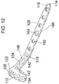
- FIG. 12 is a top perspective view of an alternative bone plate in accordance with some alternatives.
- the bone plate 110 comprises a posteromedial plate that can be inserted through an incision over a posteromedial aspect of a bone (e.g,. tibia).
- the bone plate 110 includes a number of similar features as the medial plates in FIGS. 10 and 11 , including a proximal end 112, a distal end 114, a head portion 122, a neck portion 124, and a shaft portion 126.
- the bone plate 110 includes several non-locking holes 134 in the head portion 122, as well as several stacked locking holes 162 in the shaft portion 126.
- the head portion 122 comprises a row of non-locking holes 134 (e.g., between 2.5 mm and 4.5 mm) that are positioned below a row of k-wire holes.
- the head portion 122 comprises a single non-locking hole 142 positioned below the row of non-locking holes 134.
- the shaft portion 126 comprises a series of fixed angle, stacked locking holes 162 (e.g., between 2.5 mm and 4.5 mm) including a bi-directinal dynamic compression slot 164 therebetween.
- FIG. 13 is a top perspective view of an alternative bone plate in accordance with some alternatives.
- the bone plate 110 comprises a medial plate that is inserted through an incision over a medial aspect of a bone (e.g., tibia).
- the bone plate 110 is similar to the bone plate in FIG. 11 , but includes a different hole pattern along the shaft portion 126.
- the shaft portion 126 comprises several pairs of holes - a fixed angled locking hole 162 (between 2.5 mm and 4.5 mm) adjacent a dynamic compression slot 164.
- FIG. 14 is a top perspective view of an alternative bone plate in accordance with some alternatives.
- the bone plate 110 comprises a medial plate that is inserted through an incision over a medial aspect of a bone (e.g., tibia).
- the bone plate 110 is similar to the bone plate in FIG. 13 , except the head portion 122 of the bone plate 110 includes a plurality of non-locking holes 134, 142 (between 2.5 mm and 4.5 mm) rather than locking holes.
- FIG. 15 is a top perspective view of an alternative bone plate in accordance with some alternatives.
- the bone plate 110 comprises a medial plate that is inserted through an incision over a medial aspect of a bone (e.g., tibia).
- the bone plate 110 includes a proximal end 112, a distal end 114, a head portion 122, a neck portion 124 and a shaft portion 126.
- the head portion comprises a row of polyaxial locking holes 134 (between 2.5 mm and 4.5 mm).
- the locking holes 134 are formed distally beneath suture holes 174.
- the suture holes 174 are independent from a recess 172 for a k-wire.
- the head portion 122 also includes a fixed angle locking hole 142 (between 2.5 mm and 4.5 mm).
- the neck portion 124 comprises a positioning slot 148 and an additional fixed angle locking hole 142.
- the shaft portion 126 comprises a plurality of alternating locked or unlocked holes 162 and compression slots 164.
- FIG. 16 is a top perspective view of an alternative bone plate in accordance with some alternatives.
- the bone plate 110 comprises a posteromedial plate that is inserted through an incision over a posteromedial aspect of a bone (e.g., tibia).
- the bone plate 110 includes similar features as prior embodiments, including a head portion 122 having polyaxial locking holes 134 (between 2.5 mm - 4.5 mm), suture holes 174 and a k-wire recess 172.
- the neck portion 124 includes a pair of fixed angle locking holes 142 (between 2.5 mm and 4.5 mm) and a positioning slot 148 therebetween.
- the shaft portion 126 comprises a series of in-line openings or holes 162 that can accommodate a locking or non-locking fastener therein.
- an aiming guide can be provided to assist a surgeon in placing one or more screws or fasteners into a patient.
- the aiming guide can be mounted to a bone plate, and can include guide holes that align with holes in the bone plate such that screws or fasteners can be accurately implanted into a patient.
- the guide holes can accept aiming sleeves that interface with drill guides, trocars, k-wires and screws. These sleeves can be secured to the aiming guide by a ratcheting or clipping mechanism. While the aiming guide can be particularly useful for lateral plates, the aiming guide can also be used for medial and posteromedial plates.
- FIG. 17 is a top perspective view of an aiming guide in accordance with some alternatives.
- the aiming guide 200 can be mounted to an underlying plate 10, and includes an aiming arm 210 and an aiming mount 230.
- the aiming arm 210 comprises a plurality of guide holes 262a, 262b, 262c, 262d that correspond with holes 62a, 62b, 62c, 62d of the plate 10.
- the purpose of the guide holes 262 is to help guide one or more fasteners or screws into the corresponding holes 62 with precision and accuracy.
- the guide holes 262 can receive aiming sleeves that interface with drill guides, trocars, k-wires or screws.
- the aiming arm 210 includes an opening 264 on one end for receiving an arm fixation bolt 236 therein and an opening 266 on the opposing end for receiving a distal locking bolt 238 therein.
- the arm fixation bolt 236 is configured to extend and secure the aiming arm 210 to the aiming mount 230.
- the distal locking bolt 238 is configured to engage an opening near a distal end of a bone plate 10, thereby providing a stable construct.
- the aiming arm 210 is formed of a non-metal, such as a carbon fiber. By forming the aiming arm 210 of a non-metal, this advantageously prevents it from being visible on an x-ray.
- the aiming mount 230 which is attached to the aiming arm 210, serves as a mount on the plate 10.
- the aiming mount 230 (shown in FIGS. 18 and 19 ) comprises an upright post portion including a pair of openings 244 for receiving an anti-rotation bolt 234 therein and an opening 244 for receiving a fixation bolt 232 therein.
- the fixation bolt 232 serves to attach the aiming mount 230 (and thus the entire aiming guide 200) to a plate 10.
- the fixation bolt 232 can be received in an attachment hole 44 (shown in FIG. 1 ) of the plate 10.
- the anti-rotation bolt 234 can be inserted into either of the mono-axial openings 244 to provide additional rigidity during insertion.
- the aiming mount 230 can be a different material from aiming arm 210, as the aiming mount 230 does not obstruct viewing of the holes 62 in the plate 10.
- the aiming mount 230 can be formed of metal while the aiming arm 210 can be formed of non-metal. The means of connecting the aiming arm 210 to the aiming mount 230 will not be described in more detail.
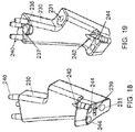
- FIG. 18 is a side view of a mount of the aiming guide of FIG. 17 .
- the aiming mount 230 comprises an upright post having an upper section and a lower section.
- the upper section comprises a plurality of openings 235 (shown in FIG. 19 ) for receiving stabilizing pins 240 therein.
- the aiming arm 210 attaches to the aiming mount 230 by sliding over the stabilizing pins 240 and tightening the arm fixation bolt 236.
- the arm fixation bolt 236 is received in a threaded mounting hole 237 (shown in FIG. 19 ) that is formed on the upper section of the aiming mount 230.
- the aiming mount 230 further comprises a lower section including openings 244 for receiving one or more anti-rotation bolts 234 (shown in FIG. 17 ).
- the one or more anti-rotation bolts 234 provide additional rigidity to the aiming mount 230.
- the lower section includes another opening 231 through which the fixation bolt 232 (shown in FIG. 17 ) extends therethrough.
- the lower section can further include a positioning feature 239 that guides and orients the aiming mount 230 into a proper position relative to the underlying bone plate 10.
- FIG. 19 is an alternative side view of a mount of the aiming guide of FIG. 17 . From this view, one can see specific features of the upper section and lower section of the aiming mount 230. In particular, in the upper section, one can see the plurality of openings 235 for receiving stabilizing pins 240 therein. In addition, one can see the threaded mounting hole 237 that receives the arm fixation bolt 236 to secure the aiming arm 210 to the aiming mount 230. Between the upper section and the lower section of the aiming mount 230 is an opening 231 for receiving the fixation bolt 232 therein. From this view, one can see the openings 244 in the lower section for receiving one or more anti-rotation bolts 234 therein.
- FIG. 20 is a top perspective view of an aiming guide comprising a distal aiming guide and an optional proximal aiming guide in accordance with some alternatives.
- the distal aiming guide 210 is capable of guiding one or more fasteners or screws into distal openings or holes (such as holes or slots 62, 64) of the bone plate 10
- the proximal aiming guide 310 is capable of guiding one or more fasteners or screws into proximal openings or holes (such as rafting holes 32, 34) of the bone plate 10.
- both the distal and proximal aiming guides 210, 310 are capable of accepting one or more aiming sleeves that interface with drill guides, trocars, k-wires, and screws. These sleeves can be secured to the respective guide by a ratcheting or clipping mechanism.
- the distal aiming guide 210 comprises an arm including a plurality of guide holes 262 formed therein.
- the plurality of guide holes 262 are sized and configured to receive one or more aiming sleeves 270 that interface with drill guides, trocars, k-wires and screws.
- the one or more aiming sleeves 270 help guide screws into holes or slots 62, 64.
- the arm includes an extension portion 263 that includes one or more additional guide holes 265 for receiving one or more aiming sleeves 270 therein.
- the one or more sleeves 270 received in the one or more guide holes 265 can be used to direct screws or fasteners into one or kickstand holes of the bone plate 10.
- the distal aiming guide 210 further comprises at least one opening for receiving an attachment post 280 therethrough.
- the attachment post 280 is configured to attach to the bone plate 10.
- the proximal aiming guide 310 comprises one or more guide holes 362 that can be used to direct screws or fasteners into the rafting holes 32, 34 of the bone plate 10.
- each of the guide holes 362 is formed of a pair of overlapping openings or circles.
- guide hole 362a is formed of a pair of overlapping openings or circles, as are guide holes 362b, 362c, 362d.
- guide hole 362a will guide a screw into rafting hole 32a
- guide hole 362b will guide a screw into rafting hole 32b
- guide hole 362c will guide a screw into rafting hole 32c
- guide hole 362d will guide a screw into rafting hole 32d.
- the dial 360 of the proximal aiming guide 310 can assume four different positions at 20 degrees apart for targeting holes in the underlying plate 10 that are coaxial with the holes 362 in the guide.
- the proximal aiming guide 310 can rotate out of the way to allow for easier visualization of the plate 10.
- the proximal aiming guide 310 comprises a dial 360 that indicates which of the guide holes 362a, 362b, 362c, 362d will be available for use. In some alternatives, only a single guide hole 362a, 362b, 362c, 362d will be available in each setting, thereby reducing the risk of confusion to a surgeon.
- the dial is rotatable and has a setting that corresponds with each of the guide holes 362, 362b, 362c, 362d.
- FIG. 21 is a top perspective view of the distal aiming guide of FIG. 20 .
- the distal aiming guide 210 comprises an arm having a plurality of guide holes 262 extending along a length of the arm.
- the guide holes 262 correspond to one or more holes or slots in the bone plate 10, thereby allowing a screw to be easily guided into a proper position on the plate.
- the guide holes 262 are coaxial with holes or slots in the bone plate 10.
- the guide holes 262 accept a guide (e.g., a sleeve) in different positions to target non-locking plate holes in either a static or eccentric position. This facilitates percutaneous insertion of non-locking screws either statically or for dynamic compression.
- the distal aiming guide 210 includes guide holes 262 that correspond with holes or slots in the shaft portion 26 of the bone plate 10, as well as guide holes 265 that correspond with kickstand holes in the neck portion 24.
- the guide holes 262 that correspond with holes or slots in the shaft portion 26 accepts only one type of aiming sleeve 270, while the guides holes 265 that correspond with the kickstand holes in the neck portion 26 accept another type of aiming sleeve 270.
- the distal aiming guide 210 can be formed of a radiolucent material to prevent obstruction of fluoroscopic imaging while in an operating room.
- the distal aiming guide 210 includes a pair of attachment arms 267, 269.
- the first attachment arm 267 comprises a first connection 281a and the second connection arm 269 comprises a second connection 281b.
- Each of these connections 281a, 281b is capable of attachment to an optional proximal aiming guide 310.
- the distal aiming guide 210 is advantageously reversible such that it is can be acceptably used via left hand or right hand.
- FIG. 22 is a bottom perspective view of an attachment post in accordance with some embodiments.
- the attachment post 280 is insertable through a connection opening 381 in the proximal aiming guide 310 (shown in FIG. 20 ), as well as through a connection 281 (shown in FIG. 21 ) in the distal aiming guide 210 (shown in FIG. 21 ).
- the attachment post 280 is configured to engage an underlying bone plate 10.
- the attachment post 280 comprises one or more ball-end pins 282 for engaging alignment indentations 44 (shown in FIG. 1 ) of the bone plate 10.
- the attachment post 280 comprises a threaded shaft 284 for threadingly attaching to an instrument attachment hole 44 in the bone plate 10.
- the attachment post 280 further comprises a stabilizing feature 287 that assists with alignment during attachment.
- FIG. 23 is a top perspective view of the proximal aiming guide of FIG. 20 . From this view, one can see the guide holes 362a, 362b, 362c, 362d, as well as the dial 360 that determines which of the guide holes 362a, 362b, 362c, 362d is available for use. In addition, FIG. 23 shows neighboring guide holes 392 through which one or more additional aiming sleeves can be inserted. In addition, a connection opening 381 is shown through which an attachment post 280 can be received therein.
- connection opening 381 in the proximal aiming guide 310 is coaxial with a connection 281 in the distal aiming guide 210, such that the attachment post 280 can extend through both the proximal aiming guide 310 and the distal aiming guide 210.
- FIG. 24 is a top perspective view of the distal aiming guide with proximal aiming guide of FIG. 20 . From this view, one can see how the attachment post 280 extends through the connection opening 381 of the proximal aiming guide 310 and into the connection 281 in the distal aiming guide 210 before engaging the bone plate 10.
- the attachment post 280 advantageously serves as a means to secure the distal aiming guide 210 with the proximal aiming guide 310.
- FIG. 25A is a view of the distal aiming guide with proximal aiming guide in a first setting.
- the aiming sleeve 270 is capable of being inserted into guide hole 362a.
- FIG. 25B is a view of the distal aiming guide with proximal aiming guide in a second setting.
- the aiming sleeve 270 is capable of being inserted into guide hole 362b.
- FIG. 25C is a view of the distal aiming guide with proximal aiming guide in a third setting.
- the aiming sleeve 270 is capable of being inserted into guide hole 362c.
- FIG. 25D is a view of the distal aiming guide with proximal aiming guide in a fourth setting.
- the aiming sleeve 270 is capable of being inserted into guide hole 362d.
- FIG. 26 is a cross-sectional view of a dial in the proximal aiming guide.
- FIG. 27 is a top perspective view of dial in the proximal aiming guide.
- the dial 360 comprises a rotating mechanism that uses a variation of a Hirth coupling 382 and a spring 384 that accommodates different settings. As the dial 360 is rotated by hand, the top coupling 382a of the Hirth coupling 382 exerts a force on the bottom coupling 382b causing it to translate axially along a shaft. Once clearance is achieved, the dial 360 will complete its designed rotation (e.g., 20 degrees) with a click.
- the retention cap 387 holds the dial 360 in place axially along the shaft and counteracts the force of the spring 384 which forces the bottom coupling 382b to translate down with the rotation.
- embodiments of the bone plates can include one or more rows of rafting openings or holes for receiving rafting screws therein.
- These rafting screws can be provided at or near an articular joint of a bone, thereby reducing the risk of subsidence at the articular joint. More details regarding the rafting screws, as well the optional use of non-threaded rafting blades, are provided below.
- FIG. 28 is a front view of a bone plate including rafting screws attached to a bone member.
- the bone plate 10 can be any of the bone plates described above and can include fasteners or screws 6 extending therethrough. As shown in the figure, the upper row of screws 6 can be considered rafting screws. These rafting screws not only help to treat a bone fracture, but they have to prevent subsidence near the articular joint.
- FIG. 29 is a side view of the bone plate of FIG. 28 . From this view, one can see the rafting screws extending across a fracture in the bone. The rafting screws are positioned adjacent to the articular joint to prevent subsidence near the articular joint.
- FIG. 30 is a top view of the bone plate of FIG. 28 . From this view, one can see how the rafting screws serve as rebar and provide support for the articular joint.
- non-threading rafting blades can be provided.
- these non-threaded blades help to (i) provide better support of an articular surface, (ii) minimize time in surgery due to ease of insertion; and (iii) have a reduced risk of post-operative back out.
- FIG. 31 is a top perspective view of a rafting blade in accordance with some embodiments.
- the rafting blade 406 can be used in addition to, or as an alternative to, the threaded rafting screws described previously.
- one or more rafting blades 406 can be inserted through a bone plate that has been secured to bone via one or more fasteners or screws. The one or more blades can then be locked to the bone plate to prevent post-operative back out.
- the rafting blade 406 comprises a proximal end 412 and a distal cutting end 414.
- the distal cutting end 414 advantageously enables the rafting blade 406 to be inserted into bone with ease, simply by impacting the proximal end 412 of the rafting blade 406.
- the rafting blade 406 is curved or arced.
- the rafting blade 406 is concave, thereby forming a concave rafting surface.
- the rafting blade 406 comprises a structural rib 422 that extends along a longitudinal axis of the rafting blade 406. The structural rib 422 and concave rafting surface advantageously improve the bending moment along the length of the rafting blade 406, thereby providing support against failure during and after insertion.
- FIG. 32 is a top view of the rafting blade of FIG. 31 . From this view, one can see how the structural rib 406 extends along a central longitudinal axis of the rafting blade 406. In some alternatives, the structural rib 406 extends along a majority of the length of the central longitudinal axis of the rafting blade 406.
- FIG. 33 is a side view of the rafting blade of FIG. 31 . From this view, one can see the concave curvature of the rafting blade 406.
- FIG. 34 is a side view of a pair of rafting blades attached to a plate in accordance with some alternatives.
- the plate 10 comprises a curved or domed plate contact surface that facilitates rotation in one plane allowing the rafting blades 406 to be inserted parallel to an articular surface regardless of plate position.
- rafting blades 406 can be inserted at a similar angle to one another. In other embodiments, rafting blades 406 can be inserted at different angles from one another.
- FIG. 35A is a front view of the rafting blade of FIG. 31 . From this view, one can see how the rafting blade 406 comprises a k-wire hole 430.
- the rafting blade 406 can be cannulated to allow guided insertion by k-wire. In some embodiments, the rafting blade 406 can be tapped into bone via use of a slotted hammer.
- FIG. 35B is a bottom perspective view of the rafting blade of FIG. 31 . From this view, one can see the underside of the rafting blade 406 and its cannulated k-wire hole 430.
- FIG. 36 is a top perspective view of an insertion guide for rafting blades in accordance with some alternatives.
- FIG. 37 is a top view of the insertion guide detached from the rafting blades of FIG. 36 .
- the insertion guide 500 allows for a set of parallel or variable angled rafting blades 406 to be inserted simultaneously into a bone member.
- a rafting blade can be individually installed. By accommodating a set of rafting blades, the insertion guide 500 advantageously reduces the time in surgery.
- the insertion guide 500 comprises a block that can temporarily engage or attach to a bone plate after the bone plate has been secured to bone.
- the block can include a series of channels or openings through which the rafting blades 406 can be inserted therein.
- a plurality of rafting blades 406 are preloaded into the insertion guide 500.
- the insertion guide 500 can be used without preloading rafting blades 406, thereby allowing a surgeon to select lengths that best suit a particular patient.
- the rafting blades 406 can be tapped into bone in sequence.
- three rafting blades 406 can be inserted in the insertion guide 500.
- the middle blade can be shaped in such a way to prevent back out of the other two rafting blades, as shown in FIG. 38 .
- FIG. 38 is a top view of the rafting blades following insertion in accordance with some alternatives.
- Three rafting blades 406 are provided in the insertion guide 500.
- the blades 406 include first blade 406a, second blade 406b, and third blade 406c.
- the blades 406 are tapped in a particular sequence such that the third blade 406c prevents backout of the first and second blades 406a, 406b.
- the third blade 406c can be sized and configured (e.g., via its proximal head portion) to prevent inadvertent backout of the first blade 406a and the second blade 406b.
- FIG. 39 is a top perspective view of rafting blades and an independent support screw in accordance with some alternatives.
- rafting blades 406 that are inserted into a bone plate 10 through rafting holes 432 are accompanied by a support screw 506.
- the support screw 506 advantageously supports the tips of the rafting blades 406 after insertion.
- FIG. 40A is a front view of a blocking mechanism for the rafting blades in accordance with some alternatives.
- FIG. 40B is a front view of the blocking mechanism of FIG. 40A rotated.
- the blocking mechanism 520 comprises a blocking screw.
- the blocking mechanism 520 comprises a rotating member that allows insertion of rafting blades 406 in one configuration, but prevents the rafting blades 406 from backing out in another rotated configuration.
- the blocking mechanism 520 can simply be installed behind the middle rafting blade 406.
- FIG. 41 is a side view of a rafting blade and locking cap in accordance with some alternatives.
- the locking cap advantageously prevents the rafting blade from toggling within a bone plate and keeps it within the bone plate.
- a locking cap 440 can be used to collapse over a spherical head 410 of a rafting blade 406.
- the outside of the locking cap 440 can have a conical surface with cutouts 442 around its diameter.
- the cutouts 442 are zigzagged or z-shaped.
- the cutouts 442 are slits.
- the inside of the locking cap 440 can be spherical to allow the variable angle installation of a rafting blade 406.
- the locking cap 440 can be threaded.
- the locking cap 440 As the locking cap 440 is threaded into a bone plate, its conical geometry and cutouts 442 allow it to collapse over the spherical head 410, grip to the grooved surface of the spherical head 410 and lock it into plate within a bone plate.
- FIG. 42 is a top perspective view of the rafting blade attached to the locking cap of FIG. 41 . From this view, one can see how the head of the rafting blade 406 is received in the locking cap 440.
- FIG. 43 is a top perspective view of the locking cap of FIG. 41 . From this view, one can see the inner portion of the threaded locking cap 440. In addition, one can see how the cutouts 442 are formed around a perimeter of the locking cap 440. As shown in FIG. 43 , cutouts 442 can be initiated at a top or bottom section of the locking cap 440.
- FIG. 44 is a top perspective view of a rafting blade having deforming ridges in accordance with some alternatives.
- FIG. 45 is a bottom perspective view of the rafting blade having deforming ridges of FIG. 44 .
- the rafting blade 406 can comprises one or more ridges 450 where it contacts a bone plate. These one or more ridges 450 can cause a small amount of deformation in the bone plate as the bone plate is inserted, which would advantageously help to lock the rafting blade 406 in place.
- the rafting blade 406 can comprise a pair of ridges 450, each of which is off-center from a longitudinal axis of the rafting blade 406.
- bone plates may be described as suitable for a particular approach (e.g., medial or lateral), one skilled in the art will appreciate that the bone plates can be used for multiple approaches.
- bone plates are described as having particular holes (e.g., locking or non-locking), one skilled in the art will appreciate that any of the bone plates can include locking, non-locking or a combination of locking and non-locking holes.
- screws and instruments described above one skilled in the art will appreciate that these described features can be used with a number of trauma treatment instruments and implants, including external fixators, ring fixators, rods, and other plates and screws.
Landscapes
- Health & Medical Sciences (AREA)
- Orthopedic Medicine & Surgery (AREA)
- Surgery (AREA)
- Life Sciences & Earth Sciences (AREA)
- Heart & Thoracic Surgery (AREA)
- Veterinary Medicine (AREA)
- Engineering & Computer Science (AREA)
- Biomedical Technology (AREA)
- Nuclear Medicine, Radiotherapy & Molecular Imaging (AREA)
- Medical Informatics (AREA)
- Molecular Biology (AREA)
- Animal Behavior & Ethology (AREA)
- General Health & Medical Sciences (AREA)
- Public Health (AREA)
- Neurology (AREA)
- Dentistry (AREA)
- Oral & Maxillofacial Surgery (AREA)
- Surgical Instruments (AREA)
Claims (8)
- Système pour traiter une fracture dans un os comprenant:une plaque à os (10) configurée pour venir en contact avec l'os,la plaque à os (10) comprenant une extrémité proximale (12), une extrémité distale (14), une partie tête (22), une partie col (24) et une partie tige (26), où la partie tête (22) comprend une première rangée de trous (32) et une seconde rangée de trous (34) pour recevoir une ou plusieurs attaches (6) à l'intérieur, où la partie tige comprend au moins un trou supplémentaire (62) pour y recevoir une attache;une pluralité d'attaches (6) reçues dans la partie tête (22) et positionnées dans la première rangée de trous et/ou la seconde rangée de trous; etau moins une attache reçue dans la partie tige et positionnée dans le au moins un trou supplémentaire,où la partie col (24) inclut un trou de fixation d'instrument fileté (44) et une pluralité de renfoncements (46) adjacents au trou de fixation d'instrument, où la pluralité de renfoncements (46) et le trou de fixation d'instrument (44) sont configurés pour coopérer avec un guide de visée (200) pour coupler le guide de visée (200) à la plaque à os (10),
oùla première rangée de trous (32) comprend quatre trous et la seconde rangée de trous (34) comprend quatre trous, la première rangée de trous (32) étant la rangée de trous la plus proximale et les trous de la première rangée de trous (32) étant conçus pour être positionnés de manière adjacente à l'extrémité proximale (12) de la plaque à os (10), etoù les trous (32) dans la première rangée de trous (32) sont de plus petite taille que les trous (34) dans la seconde rangée de trous (34). - Système selon la revendication 1, où la partie tête (22) comprend une partie la plus large de la plaque à os (10).
- Système selon la revendication 1, où la première rangée de trous (32) est composée de trous ayant un diamètre entre 2 et 3 mm, et la seconde rangée de trous (34) est composée de trous ayant un diamètre entre 3 et 4 mm.
- Système selon la revendication 1, où la partie col (24) comprend au moins trois trous de béquille (52).
- Système selon la revendication 1, où la partie col (24) comprend une fente de positionnement allongée (48).
- Système selon la revendication 5, où la fente de positionnement (48) fait au moins deux fois une longueur de l'un quelconque des trous sur la plaque à os (10).
- Système selon la revendication 1, où la partie tige (26) comprend au moins quatre trous (62).
- Système selon la revendication 7, où les au moins quatre trous (62) dans la partie tige (26) incluent une ou plusieurs fentes de compression (64).
Applications Claiming Priority (2)
| Application Number | Priority Date | Filing Date | Title |
|---|---|---|---|
| US201762470470P | 2017-03-13 | 2017-03-13 | |
| US15/592,912 US10905477B2 (en) | 2017-03-13 | 2017-05-11 | Bone stabilization systems |
Publications (2)
| Publication Number | Publication Date |
|---|---|
| EP3375392A1 EP3375392A1 (fr) | 2018-09-19 |
| EP3375392B1 true EP3375392B1 (fr) | 2021-05-05 |
Family
ID=61627007
Family Applications (1)
| Application Number | Title | Priority Date | Filing Date |
|---|---|---|---|
| EP18161322.5A Active EP3375392B1 (fr) | 2017-03-13 | 2018-03-12 | Systèmes de stabilisation d'os |
Country Status (3)
| Country | Link |
|---|---|
| US (2) | US10905477B2 (fr) |
| EP (1) | EP3375392B1 (fr) |
| JP (1) | JP7134651B2 (fr) |
Families Citing this family (24)
| Publication number | Priority date | Publication date | Assignee | Title |
|---|---|---|---|---|
| US10251757B2 (en) * | 2008-09-17 | 2019-04-09 | Skeletal Dynamics Llc | Grooved slot allowing adjustment of the position of a bone fixation device for osteosynthesis |
| US10537371B2 (en) * | 2015-12-23 | 2020-01-21 | Osteomed Llc | Wrist plate and drill guide |
| WO2017149026A2 (fr) * | 2016-03-01 | 2017-09-08 | Ot Medizintechnik Gmbh | Dispositif de positionnement pour fixer une plaque polyaxiale sur un os long |
| US11045242B2 (en) | 2016-09-22 | 2021-06-29 | Globus Medical, Inc. | Systems and methods for intramedullary nail implantation |
| US10299847B2 (en) | 2016-09-22 | 2019-05-28 | Globus Medical, Inc. | Systems and methods for intramedullary nail implantation |
| US12594108B2 (en) | 2016-09-22 | 2026-04-07 | Globus Medical Inc. | Systems and methods for intramedullary nail implantation |
| US10881438B2 (en) * | 2017-03-10 | 2021-01-05 | Globus Medical, Inc. | Clavicle fixation system |
| AU2018304170A1 (en) * | 2017-07-17 | 2020-01-30 | Mayo Foundation For Medical Education And Research | Method for optimization of orthopedic component design |
| CN109223154A (zh) * | 2018-10-22 | 2019-01-18 | 大泗医疗生物科技有限公司 | 一种骨盆万向锁定钢板 |
| WO2020237420A1 (fr) | 2019-05-24 | 2020-12-03 | Becton, Dickinson And Company | Assistant de trajet l'aiguille comprenant des composants et des procédés associés |
| EP3962564B1 (fr) * | 2019-05-24 | 2025-11-05 | Becton, Dickinson and Company | Canules de raidissement articulées et ensembles d'accès |
| US11944361B2 (en) | 2019-08-09 | 2024-04-02 | DePuy Synthes Products, Inc. | Bone plate with structures for attachment of sutures |
| US11207111B2 (en) | 2019-11-04 | 2021-12-28 | DePuy Synthes Products, Inc. | Clavicle segmental plate system |
| JP7639014B2 (ja) * | 2020-02-19 | 2025-03-04 | クロスローズ エクストリミティ システムズ リミテッド ライアビリティ カンパニー | ラピダスバニオン修復法のためのシステム及び方法 |
| CN112370141A (zh) * | 2020-10-20 | 2021-02-19 | 广东施泰宝医疗科技有限公司 | 一种带双套筒的股骨颈接骨板 |
| US11432832B2 (en) * | 2020-12-03 | 2022-09-06 | Stryker European Operations Limited | Minimally invasive surgery targeting guides and methods of use |
| EP4291114A1 (fr) * | 2021-02-11 | 2023-12-20 | Smith & Nephew, Inc. | Système de ciblage de plaque osseuse périprothétique |
| EP4215131A1 (fr) * | 2022-01-19 | 2023-07-26 | Globus Medical, Inc. | Systèmes d'implantation de clou intramédullaire |
| US20250009366A1 (en) * | 2023-07-06 | 2025-01-09 | Stryker European Operations Limited | Modular Aiming Block for Targeting System |
| US12496110B2 (en) * | 2023-07-13 | 2025-12-16 | DePuy Synthes Products, Inc. | Lateral proximal tibia plate with extension arm |
| US20250134562A1 (en) * | 2023-10-30 | 2025-05-01 | DePuy Synthes Products, Inc. | Suture hole with funnel on bone plate |
| US20250143758A1 (en) * | 2023-11-02 | 2025-05-08 | Globus Medical, Inc. | Fracture plating systems |
| USD1099319S1 (en) | 2024-06-07 | 2025-10-21 | Stryker European Operations Limited | Bone plate |
| USD1118930S1 (en) | 2024-06-07 | 2026-03-17 | Stryker European Operations Limited | Bone plate |
Citations (1)
| Publication number | Priority date | Publication date | Assignee | Title |
|---|---|---|---|---|
| US20150182267A1 (en) * | 2014-01-02 | 2015-07-02 | DePuy Synthes Products, LLC | Method and Device for Attaching a Bone Plate |
Family Cites Families (241)
| Publication number | Priority date | Publication date | Assignee | Title |
|---|---|---|---|---|
| US1105105A (en) | 1912-02-10 | 1914-07-28 | William O'n Sherman | Surgical appliance. |
| US2486303A (en) | 1948-04-29 | 1949-10-25 | Harry Herschel Leiter | Surgical appliance for bone fractures |
| US3716050A (en) | 1971-02-11 | 1973-02-13 | F Johnston | Olecranon plate |
| CH651192A5 (de) | 1980-11-20 | 1985-09-13 | Synthes Ag | Osteosynthetische vorrichtung und dazu passende bohrlehre. |
| FR2517536B1 (fr) | 1981-12-09 | 1986-12-12 | Zbikowski Juan | Dispositif de fixation fonctionnelle pour osteo-synthese au moyen de plaques de compression |
| CH662936A5 (de) | 1984-05-18 | 1987-11-13 | Technomed Gmk | Knochenverbindungsplatte. |
| US4683878A (en) | 1985-04-29 | 1987-08-04 | Kirschner Medical Corporation | Osteosynthetic fixation plate |
| PL147580B1 (en) | 1986-04-14 | 1989-06-30 | Plate for uniting epiphysis and diaphysis of broken bone | |
| US4776330A (en) | 1986-06-23 | 1988-10-11 | Pfizer Hospital Products Group, Inc. | Modular femoral fixation system |
| US4781183A (en) | 1986-08-27 | 1988-11-01 | American Cyanamid Company | Surgical prosthesis |
| DE8706912U1 (de) | 1987-05-14 | 1987-08-27 | Howmedica GmbH, 2314 Schönkirchen | Kleinknochenplatte und Schrauben, insbesondere für die Versorgung von Frakturen des Schädel- und Gesichtsskeletts o. dgl. |
| US5151103A (en) | 1987-11-03 | 1992-09-29 | Synthes (U.S.A.) | Point contact bone compression plate |
| CH673762A5 (fr) | 1987-12-02 | 1990-04-12 | Synthes Ag | |
| IT1237496B (it) | 1989-10-26 | 1993-06-08 | Giuseppe Vrespa | Dispositivo a vite per l'ancoraggio di protesi alle ossa, metodo per l'applicazione di tale dispositivo e relativa attrezzatura |
| US6001099A (en) | 1998-06-08 | 1999-12-14 | Huebner; Randall J. | Bone plate with varying rigidity |
| US5423826A (en) | 1993-02-05 | 1995-06-13 | Danek Medical, Inc. | Anterior cervical plate holder/drill guide and method of use |
| US5364399A (en) | 1993-02-05 | 1994-11-15 | Danek Medical, Inc. | Anterior cervical plating system |
| US5601553A (en) | 1994-10-03 | 1997-02-11 | Synthes (U.S.A.) | Locking plate and bone screw |
| SE505453C2 (sv) | 1995-02-14 | 1997-09-01 | Robert J Medoff | Implanteringsbar stödplatta |
| KR100329539B1 (ko) | 1995-03-27 | 2002-11-13 | 신테스 아게 츄어 | 뼈고정판 |
| DE59509247D1 (de) | 1995-09-06 | 2001-06-13 | Synthes Ag | Knochenplatte |
| US5676667A (en) | 1995-12-08 | 1997-10-14 | Hausman; Michael | Bone fixation apparatus and method |
| US5785712A (en) | 1996-04-16 | 1998-07-28 | Terray Corporation | Reconstruction bone plate |
| EP0909143A4 (fr) | 1996-06-14 | 2008-11-26 | Depuy Ace Medical Company | Plaque vissee pour extremites osseuses superieures |
| CA2179864C (fr) | 1996-06-25 | 2002-05-07 | Robert John Runciman | Modele de plaque vissee |
| EP0917450A1 (fr) | 1996-08-12 | 1999-05-26 | SYNTHES AG Chur | Plaque pour osteosynthese |
| ZA983955B (en) | 1997-05-15 | 2001-08-13 | Sdgi Holdings Inc | Anterior cervical plating system. |
| US5938664A (en) | 1998-03-31 | 1999-08-17 | Zimmer, Inc. | Orthopaedic bone plate |
| US6533786B1 (en) | 1999-10-13 | 2003-03-18 | Sdgi Holdings, Inc. | Anterior cervical plating system |
| DE19858889B4 (de) | 1998-12-19 | 2008-08-07 | Wolter, Dietmar, Prof. Dr.Med. | Fixationssystem für Knochen |
| EP1158915B1 (fr) | 1999-03-09 | 2004-09-01 | SYNTHES AG Chur | Plaque pour osteosynthese |
| US6730091B1 (en) | 1999-05-03 | 2004-05-04 | Medartis Ag | Blockable bone plate |
| US7094239B1 (en) | 1999-05-05 | 2006-08-22 | Sdgi Holdings, Inc. | Screws of cortical bone and method of manufacture thereof |
| ATE257674T1 (de) * | 1999-09-13 | 2004-01-15 | Synthes Ag | Knochenplattenvorrichtung |
| DE50011463D1 (de) | 1999-09-14 | 2005-12-01 | Wolter Dietmar | Fixationssystem für knochen |
| BR0017018A (pt) | 2000-01-27 | 2002-11-05 | Synthes Ag | Placa de osso |
| US6358250B1 (en) | 2000-02-01 | 2002-03-19 | Hand Innovations, Inc. | Volar fixation system |
| US7857838B2 (en) | 2003-03-27 | 2010-12-28 | Depuy Products, Inc. | Anatomical distal radius fracture fixation plate |
| US20040153073A1 (en) | 2000-02-01 | 2004-08-05 | Hand Innovations, Inc. | Orthopedic fixation system including plate element with threaded holes having divergent axes |
| US6712820B2 (en) | 2000-02-01 | 2004-03-30 | Hand Innovations, Inc. | Fixation plate system for dorsal wrist fracture fixation |
| US6866665B2 (en) * | 2003-03-27 | 2005-03-15 | Hand Innovations, Llc | Bone fracture fixation system with subchondral and articular surface support |
| US6283969B1 (en) | 2000-03-10 | 2001-09-04 | Wright Medical Technology, Inc. | Bone plating system |
| US6740088B1 (en) | 2000-10-25 | 2004-05-25 | Sdgi Holdings, Inc. | Anterior lumbar plate and method |
| US7153309B2 (en) | 2002-11-19 | 2006-12-26 | Acumed Llc | Guide system for bone-repair devices |
| US8523919B2 (en) | 2010-09-27 | 2013-09-03 | Acumed Llc | Targeting guide with a radiopaque marker to facilitate positioning a bone plate on bone |
| US8518090B2 (en) | 2010-10-05 | 2013-08-27 | Acumed Llc | Fastener with serrated thread for attachment to a bone plate at a selectable angle |
| CN100484490C (zh) | 2001-05-28 | 2009-05-06 | 斯恩蒂斯有限公司 | 用于近中的肱骨骨折固定术的接骨板 |
| JP2003210478A (ja) | 2002-01-18 | 2003-07-29 | Ai-Medic:Kk | 尺骨近位端粉砕骨折固定用プレート |
| US7322983B2 (en) | 2002-02-12 | 2008-01-29 | Ebi, L.P. | Self-locking bone screw and implant |
| US7862597B2 (en) | 2002-08-22 | 2011-01-04 | Warsaw Orthopedic, Inc. | System for stabilizing a portion of the spine |
| US7179260B2 (en) | 2003-09-29 | 2007-02-20 | Smith & Nephew, Inc. | Bone plates and bone plate assemblies |
| FR2845588B1 (fr) | 2002-10-09 | 2006-12-15 | Biotech Internat | Dispositif d'osteosynthese autobloquant |
| US6955677B2 (en) | 2002-10-15 | 2005-10-18 | The University Of North Carolina At Chapel Hill | Multi-angular fastening apparatus and method for surgical bone screw/plate systems |
| FR2846870B1 (fr) | 2002-11-07 | 2005-07-01 | Fixano | Materiel d'osteosynthese pour le traitement d'un cubitus"long" |
| US20040097937A1 (en) | 2002-11-19 | 2004-05-20 | Sandi Pike | Orthopedic bone plate |
| US20050187551A1 (en) | 2002-12-02 | 2005-08-25 | Orbay Jorge L. | Bone plate system with bone screws fixed by secondary compression |
| US7722653B2 (en) | 2003-03-26 | 2010-05-25 | Greatbatch Medical S.A. | Locking bone plate |
| CN1764418B (zh) | 2003-03-26 | 2010-05-26 | 瑞士整形外科技术股份有限公司 | 锁定接骨板 |
| US7635381B2 (en) | 2003-03-27 | 2009-12-22 | Depuy Products, Inc. | Anatomical distal radius fracture fixation plate with fixed-angle K-wire holes defining a three-dimensional surface |
| US7250053B2 (en) | 2003-03-27 | 2007-07-31 | Depuy Products, Inc. | Low profile distal radius fracture fixation plate |
| US7294130B2 (en) | 2003-03-27 | 2007-11-13 | Depuy Products, Inc. | Distal radius fracture fixation plate having K-wire hole structured to fix a K-wire in one dimension relative to the plate |
| US7951176B2 (en) * | 2003-05-30 | 2011-05-31 | Synthes Usa, Llc | Bone plate |
| US7776076B2 (en) | 2004-05-11 | 2010-08-17 | Synthes Usa, Llc | Bone plate |
| US20050131413A1 (en) | 2003-06-20 | 2005-06-16 | O'driscoll Shawn W. | Bone plate with interference fit screw |
| US8105367B2 (en) | 2003-09-29 | 2012-01-31 | Smith & Nephew, Inc. | Bone plate and bone plate assemblies including polyaxial fasteners |
| AU2003271507B2 (en) | 2003-10-30 | 2009-04-09 | Synthes Gmbh | Bone plate |
| JP2007509730A (ja) | 2003-11-05 | 2007-04-19 | ケーニヒゼー インプランタテ ウント インストゥルメンテ ズール オステオシンテーゼ ゲーエムベーハー | 橈骨遠位端骨折を固定するためのプレート |
| AU2003280078B2 (en) | 2003-11-18 | 2010-07-01 | Synthes Gmbh | Set of osteosynthesis plates |
| US7637928B2 (en) | 2004-01-26 | 2009-12-29 | Synthes Usa, Llc | Variable angle locked bone fixation system |
| US8574268B2 (en) | 2004-01-26 | 2013-11-05 | DePuy Synthes Product, LLC | Highly-versatile variable-angle bone plate system |
| US7632277B2 (en) | 2004-03-29 | 2009-12-15 | Woll Bioorthopedics Llc | Orthopedic intramedullary fixation system |
| US7137987B2 (en) | 2004-07-02 | 2006-11-21 | Wright Medical Technology, Inc. | Distal radius bone plating system with locking and non-locking screws |
| CA2579049A1 (fr) | 2004-09-07 | 2006-03-16 | Smith & Nephew, Inc. | Mecanisme de blocage de plaque vissee presentant une epaisseur minimale |
| US20060173458A1 (en) | 2004-10-07 | 2006-08-03 | Micah Forstein | Bone fracture fixation system |
| US8043297B2 (en) * | 2004-11-03 | 2011-10-25 | Synthes Usa, Llc | Aiming arm for bone plates |
| US8394130B2 (en) | 2005-03-17 | 2013-03-12 | Biomet C.V. | Modular fracture fixation system |
| US8062296B2 (en) | 2005-03-17 | 2011-11-22 | Depuy Products, Inc. | Modular fracture fixation plate system with multiple metaphyseal and diaphyseal plates |
| US7604657B2 (en) | 2005-09-19 | 2009-10-20 | Depuy Products, Inc. | Bone fixation plate with complex suture anchor locations |
| US8172886B2 (en) | 2004-12-14 | 2012-05-08 | Depuy Products, Inc. | Bone plate with pre-assembled drill guide tips |
| US8118846B2 (en) | 2005-01-28 | 2012-02-21 | Orthohelix Surgical Designs, Inc. | Orthopedic plates for use in clavicle repair and methods for their use |
| EP1693013A1 (fr) | 2005-02-22 | 2006-08-23 | Kyon | Vis et plaque pour le traitement des fractures osseuses |
| US20060241607A1 (en) | 2005-03-31 | 2006-10-26 | Mark Myerson | Metatarsal fixation plate |
| US8382807B2 (en) * | 2005-07-25 | 2013-02-26 | Smith & Nephew, Inc. | Systems and methods for using polyaxial plates |
| EP1919385B1 (fr) | 2005-07-25 | 2014-08-20 | Smith & Nephew, Inc. | Plaques polyaxiales |
| US8177820B2 (en) | 2005-09-01 | 2012-05-15 | Merete Medical Gmbh | Bone plate comprising at least one screw to be fixed at a stable angle |
| CN101296663B (zh) | 2005-10-25 | 2011-05-25 | 圣歌整形外科有限责任公司 | 骨固定组件及与其一起使用的套管和螺钉 |
| DE502005002257D1 (de) | 2005-12-23 | 2008-01-24 | Aap Implantate Ag | Knochenplatte |
| US8491593B2 (en) | 2006-01-17 | 2013-07-23 | Stryker Trauma Gmbh | Targeting device for orthopedic implants |
| US7473255B2 (en) | 2006-02-08 | 2009-01-06 | Synthes (U.S.A.) | Transbuccal plate holding cannula |
| US8523921B2 (en) | 2006-02-24 | 2013-09-03 | DePuy Synthes Products, LLC | Tibial plateau leveling osteotomy plate |
| US7875062B2 (en) | 2006-03-07 | 2011-01-25 | Warsaw Orthopedic, Inc. | Methods and devices for retaining bone plate anchors |
| US8808334B2 (en) | 2006-03-07 | 2014-08-19 | Orthohelix Surgical Designs, Inc. | Orthopedic plate |
| US9687282B2 (en) | 2006-03-07 | 2017-06-27 | Orthohelix Surgical Designs, Inc. | Orthopedic plate having threaded holes for locking screws or pegs and non-threaded holes for a variable axis locking mechanism |
| BRPI0601069B1 (pt) | 2006-03-17 | 2014-10-14 | Gm Dos Reis Ind E Com Ltda | Placa óssea |
| US7867261B2 (en) | 2006-03-17 | 2011-01-11 | Depuy Products, Inc. | Bone plate with variable torsional stiffness at fixed angle holes |
| US7951178B2 (en) | 2006-04-03 | 2011-05-31 | Acumed Llc | Bone plates with hybrid apertures |
| US8926675B2 (en) | 2006-04-11 | 2015-01-06 | Biomet Manufacturing, Llc | Contoured bone plate |
| US20070270849A1 (en) * | 2006-04-21 | 2007-11-22 | Orbay Jorge L | Fixation Plate With Multifunctional Holes |
| JP5422858B2 (ja) | 2006-07-07 | 2014-02-19 | スイス プロ オーソペディック ソシエテ アノニム | 開放スペースによって接合された複合調節孔のある骨プレート |
| WO2008007194A2 (fr) | 2006-07-07 | 2008-01-17 | Precimed, S.A. | Plaque vissée à trous complexes adjacents reliés par une zone de dégagement pour flexion |
| US8057520B2 (en) | 2006-07-18 | 2011-11-15 | Orthohelix Surgical Designs, Inc. | Calcaneal plate |
| US8267972B1 (en) * | 2006-12-01 | 2012-09-18 | Gehlert Rick J | Bone plate |
| US20080234749A1 (en) | 2007-01-26 | 2008-09-25 | Zimmer Technology, Inc. | Bone plate providing threaded locking head screw capture |
| US8870931B2 (en) | 2007-03-21 | 2014-10-28 | The University Of North Carolina At Chapel Hill | Anti-unscrewing and multi-angular fastening apparatuses and methods for surgical bone screw/plate systems |
| EP2142122A1 (fr) | 2007-04-27 | 2010-01-13 | Synthes GmbH | Dispositifs de type implants fabriqués avec des composants métalliques et polymères |
| EP1987792B1 (fr) | 2007-05-03 | 2011-06-22 | Medartis AG | Dispositif de fixation, association d'un dispositif de fixation avec un élément longitudinal, dispositif doté d'une telle association tout comme kit d'ostéosynthèse |
| US8644909B2 (en) * | 2007-07-12 | 2014-02-04 | T. Derek V. Cooke | Radiographic imaging method and apparatus |
| AR061999A1 (es) | 2007-07-18 | 2008-08-10 | Pizzicara Mario Angel | Placa bloqueada de orificios combinados, control de estabilidad y doble angulacion, para union de huesos fracturados |
| US7602883B2 (en) * | 2007-07-20 | 2009-10-13 | St. John Companies, Inc. | Multi-density skin marker |
| US8182517B2 (en) | 2007-11-02 | 2012-05-22 | Depuy Products, Inc. | Fracture fixation plate for the olecranon of the proximal ulna |
| US8317842B2 (en) | 2007-11-30 | 2012-11-27 | Biomet C.V. | Distal tibia plating system |
| EP2072016B1 (fr) * | 2007-12-17 | 2012-10-03 | Stryker Leibinger GmbH & Co. KG | Instrument pour plaque osseuse et procédé |
| AU2009212274A1 (en) | 2008-02-06 | 2009-08-13 | Osteomed Llc | Subcondylar fracture fixation plate system for tubular bones of the hand |
| US8257403B2 (en) | 2008-02-19 | 2012-09-04 | Orthohelix Surgical Designs, Inc. | Orthopedic plate for use in the midfoot |
| US8167918B2 (en) | 2008-02-19 | 2012-05-01 | Orthohelix Surgical Designs, Inc. | Orthopedic plate for use in the MTP joint |
| US8257406B2 (en) | 2008-02-19 | 2012-09-04 | Orthohelix Surgical Designs, Inc. | Orthopedic plate for use on a single ray in the midfoot |
| FR2928259B1 (fr) | 2008-03-07 | 2011-04-22 | D L P Sarl | Materiel pour la reduction d'une fracture,en particulier d'une fracture de radius distal |
| EP2252224A4 (fr) | 2008-03-10 | 2012-06-06 | Gonzalez Hernandez Eduardo | Système de fixation d os |
| US8728126B2 (en) | 2008-03-10 | 2014-05-20 | Dennis L. Steffen | Bone fixation system and method |
| US20090248084A1 (en) | 2008-03-27 | 2009-10-01 | Beat Hintermann | Systems and methods for performing ankle arthrodesis in a human patient |
| WO2009121144A1 (fr) | 2008-04-03 | 2009-10-08 | Austofix Group Limited | Gabarit d'outil pour ensemble implant osseux |
| US8177822B2 (en) | 2008-05-05 | 2012-05-15 | Lars G. Tellman | Contoured bone plate for fracture fixation having hook members and drill guide for same |
| US8821508B2 (en) | 2008-05-05 | 2014-09-02 | Trimed, Incorporated | Holder/impactor for contoured bone plate for fracture fixation |
| WO2009148762A2 (fr) | 2008-05-09 | 2009-12-10 | Skeletal Dynamics Llc | Plaque osseuse façonnable, appareil de serrage, système d’ostéotomie et procédé pour la reconstruction d’un os |
| US8343155B2 (en) | 2008-05-15 | 2013-01-01 | Zimmer, Inc. | Cable button |
| SE533632C2 (sv) | 2008-07-01 | 2010-11-09 | Swemac Innovation Ab | Anordning för intern fixering av benfragmenten i en strålbensfraktur |
| US9072555B2 (en) | 2008-07-21 | 2015-07-07 | Arthrex, Inc. | Carbon fiber reinforced peek bone plate with titanium fixation screws |
| US8262707B2 (en) | 2008-07-31 | 2012-09-11 | Biomet C.V. | Periarticular bone plate with biplanar offset head member |
| US8257405B2 (en) | 2008-07-31 | 2012-09-04 | Biomet C.V. | Periarticular bone plate with biplanar offset head member |
| US20100057086A1 (en) | 2008-08-29 | 2010-03-04 | Zimmer, Inc. | Anodized locking plate components |
| ES2533802T3 (es) | 2008-09-02 | 2015-04-14 | Stryker Trauma Sa | Dispositivo localizador para una placa ósea |
| US8906076B2 (en) | 2008-10-17 | 2014-12-09 | Osteomed Llc | Angulated locking plate and screw |
| US8597334B2 (en) | 2008-10-17 | 2013-12-03 | Osteomed Llc | Angulated locking plate/screw interface |
| DE102008043370A1 (de) | 2008-10-31 | 2010-05-06 | Universität Rostock | Fixationsvorrichtung für Knochen |
| US8403966B2 (en) | 2008-11-24 | 2013-03-26 | Mbd Medical Llc | Clavicle plate and screws |
| US8444679B2 (en) | 2008-11-24 | 2013-05-21 | Mbd Medical Llc | Clavicle plate and screws |
| US8439918B2 (en) | 2008-12-02 | 2013-05-14 | Suspension Orthopaedic Solutions, Inc. | Ulna fixation |
| US8777998B2 (en) | 2009-02-23 | 2014-07-15 | Orthopediatrics Corp. | Pediatric long bone support or fixation plate |
| EP2410929B1 (fr) | 2009-03-24 | 2019-06-26 | Stabiliz Orthopedics, LLC | Dispositif de fixation orthopédique avec couche biorésorbable |
| WO2010113296A1 (fr) | 2009-04-01 | 2010-10-07 | 三菱電機株式会社 | Dispositif de climatisation |
| DE102009016394B4 (de) | 2009-04-07 | 2016-02-11 | Merete Medical Gmbh | Vorrichtung zur winkelstabilen Fixation und Kompression einer Bruchstelle bzw. Osteotomie an einem Knochen |
| EP2238936B1 (fr) | 2009-04-09 | 2012-05-23 | Arthrex, Inc. | Clou de clavicule avec embout de verrouillage |
| EP2248479B1 (fr) | 2009-05-06 | 2012-09-19 | Greatbatch Ltd. | Ensemble formant une lame osseuse |
| US8808333B2 (en) | 2009-07-06 | 2014-08-19 | Zimmer Gmbh | Periprosthetic bone plates |
| US8834532B2 (en) | 2009-07-07 | 2014-09-16 | Zimmer Gmbh | Plate for the treatment of bone fractures |
| US9259255B2 (en) | 2009-07-15 | 2016-02-16 | Orthohelix Surgical Designs, Inc. | Variable axis locking mechanism for use in orthopedic implants |
| US20130123841A1 (en) | 2009-09-30 | 2013-05-16 | Thomas Lyon | Apparatus and Method for a Suture Button |
| US8235594B2 (en) * | 2009-11-02 | 2012-08-07 | Carn Ronald M | Alignment fixture for X-ray images |
| EP2501312B1 (fr) | 2009-11-16 | 2016-07-20 | The Research Foundation for The State University of New York | Clou intramédullaire préincurvé pour clavicule et procédé pour l'utiliser |
| EP2515779B1 (fr) | 2009-12-22 | 2016-03-02 | Merete Medical GmbH | Système de plaques osseuses pour ostéosynthèse |
| US9486262B2 (en) | 2010-01-27 | 2016-11-08 | DePuy Synthes Products, Inc. | System and method for minimally invasive clavicle plate application |
| BR112012021877B1 (pt) | 2010-03-04 | 2020-05-26 | Synthes Gmbh | Sistema para osteotomia da ulna |
| US8764751B2 (en) | 2010-03-04 | 2014-07-01 | Skeletal Dynamics, Llc | Endosteal nail plate for fixing bone segments |
| US20110218580A1 (en) | 2010-03-08 | 2011-09-08 | Stryker Trauma Sa | Bone fixation system with curved profile threads |
| US9113970B2 (en) | 2010-03-10 | 2015-08-25 | Orthohelix Surgical Designs, Inc. | System for achieving selectable fixation in an orthopedic plate |
| US20120059424A1 (en) | 2010-03-10 | 2012-03-08 | Advanced Orthopaedic Solutions, Inc. | Clavicle Bone Plate |
| US8603148B2 (en) | 2010-05-07 | 2013-12-10 | Raymond B. Raven, III | System for treating bone fractures |
| EP2389884B1 (fr) * | 2010-05-25 | 2013-07-31 | Stryker Trauma SA | Implant pour fixation osseuse |
| USD643121S1 (en) | 2010-05-27 | 2011-08-09 | Ebi, Llc | Orthopedic wrist spanning bone plate |
| USD646785S1 (en) | 2010-05-27 | 2011-10-11 | Ebi, Llc | Orthopedic volar bone plate |
| WO2011154891A2 (fr) | 2010-06-07 | 2011-12-15 | Carbofix Orthopedics Ltd. | Implant osseux en matériau composite et procédés |
| DE102010025001B4 (de) | 2010-06-24 | 2016-08-04 | Aap Implantate Ag | Fixationssystem mit Knochenplatte und Knochenschraube |
| WO2011163092A2 (fr) | 2010-06-25 | 2011-12-29 | Amit Gupta | Système de plaque pour la prise en charge d'une fracture osseuse |
| EP2611376B1 (fr) | 2010-09-02 | 2016-08-31 | Neosteo | Dispositif d'ostéosynthèse |
| BR112013005612A2 (pt) | 2010-09-09 | 2016-05-03 | Synthes Gmbh | bastonete cirúrgico |
| PL2623057T3 (pl) | 2010-09-28 | 2024-05-06 | Olympus Terumo Biomaterials Corp. | Płytka kostna oraz system płytek kostnych |
| US8523862B2 (en) * | 2011-04-04 | 2013-09-03 | Stryker Leibinger Gmbh & Co. Kg | Bone plate aiming block |
| US8641741B2 (en) | 2010-10-13 | 2014-02-04 | Stryker Leibinger Gmbh & Co. Kg | Bone plate aiming block |
| EP3527144B1 (fr) | 2010-11-17 | 2023-12-13 | Arthrex Inc | Structure de bouton de suture réglable pour la réparation de la syndesmose de la cheville |
| CN201987653U (zh) | 2010-12-22 | 2011-09-28 | 蔡林 | 一种锁骨钩钢板 |
| US8551095B2 (en) | 2011-02-02 | 2013-10-08 | Bionet Manufacturing, LLC | Bone plate having combination locking and compression screw holes |
| CN103429173B (zh) | 2011-03-04 | 2016-08-24 | 新特斯有限责任公司 | 模块化钩板组件 |
| EP2686563B1 (fr) | 2011-03-14 | 2019-06-19 | Amit Sinha | Vis de verrouillage et plaquettes |
| CN103491889B (zh) | 2011-04-01 | 2016-10-12 | 新特斯有限责任公司 | 脊椎后路板固定系统 |
| EP2709545A1 (fr) | 2011-05-17 | 2014-03-26 | Dietmar Wolter | Plaque ostéologique |
| WO2012158253A1 (fr) * | 2011-05-18 | 2012-11-22 | Synthes Usa, Llc | Viseur sur plaque |
| US8728082B2 (en) | 2011-05-26 | 2014-05-20 | Biomet Manufacturing, Llc | Bone plate positioning scaffold |
| CN103717179B (zh) * | 2011-06-15 | 2017-08-08 | 史密夫和内修有限公司 | 可变角度锁定植入物 |
| US20130006246A1 (en) | 2011-06-30 | 2013-01-03 | Dodson Mark | Distal Radius Plate |
| US20130018426A1 (en) | 2011-07-11 | 2013-01-17 | Feng-Te Tsai | Bone Plate Module with Adjustable Fixing Direction and an Adjustment Ring Thereof |
| US9119646B2 (en) * | 2011-08-07 | 2015-09-01 | Zimmer Knee Creations, Inc. | Subchondral treatment to prevent the progression of osteoarthritis of the joint |
| EP2744431B1 (fr) * | 2011-08-19 | 2016-04-20 | Orthogrid Systems, Inc. | Appareil de plaque d'alignement |
| CN202313691U (zh) | 2011-09-01 | 2012-07-11 | 吴荣博 | 尺骨近端钩板 |
| US10098677B2 (en) | 2011-09-06 | 2018-10-16 | Globus Medical, Inc. | Spinal plate |
| WO2013036362A1 (fr) | 2011-09-06 | 2013-03-14 | Synthes Usa, Llc | Plaque vissée pour arthrodèse pancarpienne |
| DE202011106835U1 (de) | 2011-10-14 | 2012-02-06 | Königsee Implantate GmbH | Knochenplatte |
| TWI452992B (zh) | 2011-10-17 | 2014-09-21 | Taichung Veterans General Hospital Vacrs | Interlocking plate system |
| WO2013059090A1 (fr) | 2011-10-17 | 2013-04-25 | Biomet Trauma, LLC | Système de placage d'os à verrouillage variable |
| TW201316942A (zh) | 2011-10-28 | 2013-05-01 | Plus Biotechnology Co Ltd A | 鎖骨骨板以及鎖骨骨板組 |
| US8632574B2 (en) | 2011-12-07 | 2014-01-21 | Biomet C.V. | Reduced component bone plating system |
| US20130150902A1 (en) | 2011-12-13 | 2013-06-13 | Neoortho Produtos Ortopedicos | Blocked bone plate and screw provided with a threaded conic or parabolic head and arrangement comprising an implant and respective insertion method of said implant to a bone tissue |
| US9320554B2 (en) | 2011-12-22 | 2016-04-26 | Stryker European Holdings I, Llc | Wrist fusion plate |
| US9259217B2 (en) | 2012-01-03 | 2016-02-16 | Biomet Manufacturing, Llc | Suture Button |
| US9107718B2 (en) | 2012-01-10 | 2015-08-18 | Biomet Manufacturing, Llc | Bone plate |
| US8790378B2 (en) * | 2012-02-02 | 2014-07-29 | Biomet C.V. | Distal radius fracture fixation plate with integrated and adjustable volar ulnar facet support |
| US9050151B2 (en) | 2012-03-06 | 2015-06-09 | Stryker Trauma Sa | Bone plate and aiming block |
| EP2838458B1 (fr) | 2012-04-18 | 2018-09-12 | Materialise N.V. | Systèmes et procédés de fixation d'os orthopédiques |
| EP2852342A4 (fr) | 2012-05-22 | 2016-01-06 | Austofix Group Ltd | Dispositif de fixation osseuse |
| US9387022B2 (en) | 2012-06-27 | 2016-07-12 | DePuy Synthes Products, Inc. | Variable angle bone fixation device |
| US9265542B2 (en) | 2012-06-27 | 2016-02-23 | DePuy Synthes Products, Inc. | Variable angle bone fixation device |
| US9433452B2 (en) | 2012-08-03 | 2016-09-06 | Nextremity Solutions, Llc | Bone fixation device and method |
| FR2994380B1 (fr) | 2012-08-13 | 2015-07-17 | Biotech Ortho | Plaque de coaptation de fragments d'os et procedes de fabrication d'une telle plaque. |
| CN202821574U (zh) | 2012-08-27 | 2013-03-27 | 熊鹰 | 一种全锁式肩部骨折内固定装置及定位导向装置 |
| CN202821575U (zh) | 2012-09-04 | 2013-03-27 | 黄淑明 | 一种尺骨远端解剖锁定型接骨板 |
| US20140066998A1 (en) | 2012-09-06 | 2014-03-06 | Jean-Jacques Martin | Assembly comprising an implantable part designed to be fastened to one or more bones or bone portions to be joined, and at least one screw for fastening the implantable part to said bone(s) |
| EP2730244B1 (fr) * | 2012-11-07 | 2017-04-26 | Arthrex, Inc. | Plaque osseuse à trous de suture pour rattacher des tissus mous sur la zone diaphysaire de la plaque |
| US10206727B2 (en) | 2013-01-11 | 2019-02-19 | Wright Medical Technology, Inc. | Apparatus for the fixation of proximal humerus fractures |
| US9107711B2 (en) | 2013-02-20 | 2015-08-18 | Stryker Trauma Sa | Screw thread with flattened peaks |
| US20160022336A1 (en) | 2013-03-08 | 2016-01-28 | Edward Richard Bateman | Apparatus for Humeral Fracture Repair |
| US20140277178A1 (en) | 2013-03-13 | 2014-09-18 | Wright Medical Technology, Inc. | Posterior Ankle Fusion Plate |
| US20140277181A1 (en) | 2013-03-14 | 2014-09-18 | Arthrex, Inc. | Variable angle locking screw and plate |
| US9510880B2 (en) | 2013-08-13 | 2016-12-06 | Zimmer, Inc. | Polyaxial locking mechanism |
| US9468479B2 (en) | 2013-09-06 | 2016-10-18 | Cardinal Health 247, Inc. | Bone plate |
| CN203506858U (zh) | 2013-10-30 | 2014-04-02 | 丽水市中心医院 | 一种用于尺骨远端骨折的内固定板 |
| AU2014259507B2 (en) | 2013-11-08 | 2019-05-30 | Trimed Inc. | Drill guides and inserters for bone plates having hook members |
| ITPI20130095A1 (it) | 2013-11-11 | 2015-05-12 | Umberto Ragghianti | Placca per osteosintesi del perone distale / malleolo laterale e metodo relativo. |
| US9730711B2 (en) * | 2013-12-11 | 2017-08-15 | DePuy Synthes Products, Inc. | Aiming device for targeted drilling of bone |
| US9855083B2 (en) | 2013-12-12 | 2018-01-02 | Extremity Designs, Llc | Bone plate with elevated suture hole structures |
| US20160166297A1 (en) | 2013-12-12 | 2016-06-16 | Extremity Designs, Llc | Bone plate with elevated suture hole structures |
| EP3091912B1 (fr) * | 2014-01-08 | 2023-10-25 | Smith&Nephew, Inc. | Système de guidage de foret |
| US9987061B2 (en) | 2014-01-28 | 2018-06-05 | Biomet C.V. | Implant with suspended locking holes |
| US9545277B2 (en) | 2014-03-11 | 2017-01-17 | DePuy Synthes Products, Inc. | Bone plate |
| US10226287B2 (en) | 2014-03-31 | 2019-03-12 | Association For The Advancement Of Musculoskeletal | Bone plate with versatile screw holes |
| WO2015164355A1 (fr) | 2014-04-21 | 2015-10-29 | The General Hospital Corporation | Dispositif de fixation de fracture comportant une agrafe pour stabiliser un clou intramédullaire |
| CN203815563U (zh) | 2014-04-29 | 2014-09-10 | 爱派司生技股份有限公司 | 表面具抗氧化层的锁骨固定器 |
| WO2016004439A1 (fr) * | 2014-07-03 | 2016-01-07 | Acumed Llc | Plaque osseuse à raccord mobile |
| US20160045238A1 (en) | 2014-08-13 | 2016-02-18 | Biomet C.V. | Calcaneal bone plate targeting guide |
| US9730686B2 (en) * | 2014-09-03 | 2017-08-15 | Biomet C.V. | System and method of soft tissue anchoring to metaphyseal bone plate |
| GB2532721B (en) | 2014-11-21 | 2021-02-10 | Everost Uk Ltd | Bone fixation plate |
| US10226289B2 (en) | 2015-01-09 | 2019-03-12 | Biomet Manufacturing, Llc | Anatomic distal fibula plate with anterolateral directed syndesmosis screw holes |
| CN105982727A (zh) | 2015-02-11 | 2016-10-05 | 张长青 | 锁骨钩骨板 |
| US10238438B2 (en) | 2015-04-22 | 2019-03-26 | Flower Orthopedics Corporation | Proximal humeral fracture plate |
| JP6600010B2 (ja) | 2015-04-24 | 2019-10-30 | バイオメット マニュファクチャリング,リミティド ライアビリティ カンパニー | 鎖骨インプラント |
| WO2017030557A1 (fr) * | 2015-08-17 | 2017-02-23 | Orthogrid Systems, Inc. | Système de positionnement chirurgical, appareil et procédé d'utilisation |
| FR3040132B1 (fr) | 2015-08-19 | 2021-11-12 | In2Bones | Sabot d'aide au positionnement et a la fixation d'un implant chirurgical |
| US10687874B2 (en) | 2015-08-27 | 2020-06-23 | Globus Medical, Inc | Proximal humeral stabilization system |
| US10966765B2 (en) | 2015-09-05 | 2021-04-06 | Life Spine, Inc. | Orthopedic implants with variable angle bone screw locking |
| US10357293B2 (en) | 2016-02-02 | 2019-07-23 | Stryker European Holdings I, Llc | Bone plate with alternating chamfers |
| WO2017158592A2 (fr) * | 2016-03-13 | 2017-09-21 | David Tolkowsky | Appareil et procédés à utiliser avec des procédures relatives au squelette |
| US10716682B2 (en) * | 2017-07-19 | 2020-07-21 | Acumed Llc | Orthopedic alignment guide |
| US10639079B2 (en) * | 2017-10-24 | 2020-05-05 | Straight Shot, LLC | Surgical implant alignment device |
-
2017
- 2017-05-11 US US15/592,912 patent/US10905477B2/en active Active
-
2018
- 2018-01-29 US US15/882,338 patent/US20180256222A1/en not_active Abandoned
- 2018-03-12 EP EP18161322.5A patent/EP3375392B1/fr active Active
- 2018-03-12 JP JP2018044110A patent/JP7134651B2/ja active Active
Patent Citations (1)
| Publication number | Priority date | Publication date | Assignee | Title |
|---|---|---|---|---|
| US20150182267A1 (en) * | 2014-01-02 | 2015-07-02 | DePuy Synthes Products, LLC | Method and Device for Attaching a Bone Plate |
Also Published As
| Publication number | Publication date |
|---|---|
| US20180256222A1 (en) | 2018-09-13 |
| US20180256223A1 (en) | 2018-09-13 |
| JP2018149297A (ja) | 2018-09-27 |
| US10905477B2 (en) | 2021-02-02 |
| JP7134651B2 (ja) | 2022-09-12 |
| EP3375392A1 (fr) | 2018-09-19 |
Similar Documents
| Publication | Publication Date | Title |
|---|---|---|
| EP3375392B1 (fr) | Systèmes de stabilisation d'os | |
| US12089883B2 (en) | Bone stabilization systems | |
| US11871970B2 (en) | Bone stabilization systems | |
| US8864802B2 (en) | Implant for bone fixation | |
| US7727264B2 (en) | Intramedullary fixation device for metaphyseal long bone fractures | |
| US11771480B2 (en) | Distal tibial plating system | |
| US12042194B2 (en) | Bone stabilization systems | |
| US20250325312A1 (en) | Distal tibial plating system | |
| US20080262498A1 (en) | Double locked hip implant | |
| EP3542739A1 (fr) | Systèmes de stabilisation d'os | |
| US12390254B2 (en) | Bone stabilization systems | |
| US20190076175A1 (en) | Bone stabilization systems |
Legal Events
| Date | Code | Title | Description |
|---|---|---|---|
| PUAI | Public reference made under article 153(3) epc to a published international application that has entered the european phase |
Free format text: ORIGINAL CODE: 0009012 |
|
| STAA | Information on the status of an ep patent application or granted ep patent |
Free format text: STATUS: THE APPLICATION HAS BEEN PUBLISHED |
|
| AK | Designated contracting states |
Kind code of ref document: A1 Designated state(s): AL AT BE BG CH CY CZ DE DK EE ES FI FR GB GR HR HU IE IS IT LI LT LU LV MC MK MT NL NO PL PT RO RS SE SI SK SM TR |
|
| AX | Request for extension of the european patent |
Extension state: BA ME |
|
| STAA | Information on the status of an ep patent application or granted ep patent |
Free format text: STATUS: REQUEST FOR EXAMINATION WAS MADE |
|
| 17P | Request for examination filed |
Effective date: 20190318 |
|
| RBV | Designated contracting states (corrected) |
Designated state(s): AL AT BE BG CH CY CZ DE DK EE ES FI FR GB GR HR HU IE IS IT LI LT LU LV MC MK MT NL NO PL PT RO RS SE SI SK SM TR |
|
| STAA | Information on the status of an ep patent application or granted ep patent |
Free format text: STATUS: EXAMINATION IS IN PROGRESS |
|
| 17Q | First examination report despatched |
Effective date: 20200623 |
|
| GRAP | Despatch of communication of intention to grant a patent |
Free format text: ORIGINAL CODE: EPIDOSNIGR1 |
|
| STAA | Information on the status of an ep patent application or granted ep patent |
Free format text: STATUS: GRANT OF PATENT IS INTENDED |
|
| INTG | Intention to grant announced |
Effective date: 20201113 |
|
| GRAS | Grant fee paid |
Free format text: ORIGINAL CODE: EPIDOSNIGR3 |
|
| GRAA | (expected) grant |
Free format text: ORIGINAL CODE: 0009210 |
|
| STAA | Information on the status of an ep patent application or granted ep patent |
Free format text: STATUS: THE PATENT HAS BEEN GRANTED |
|
| AK | Designated contracting states |
Kind code of ref document: B1 Designated state(s): AL AT BE BG CH CY CZ DE DK EE ES FI FR GB GR HR HU IE IS IT LI LT LU LV MC MK MT NL NO PL PT RO RS SE SI SK SM TR |
|
| REG | Reference to a national code |
Ref country code: GB Ref legal event code: FG4D |
|
| REG | Reference to a national code |
Ref country code: CH Ref legal event code: EP |
|
| REG | Reference to a national code |
Ref country code: AT Ref legal event code: REF Ref document number: 1388830 Country of ref document: AT Kind code of ref document: T Effective date: 20210515 |
|
| REG | Reference to a national code |
Ref country code: IE Ref legal event code: FG4D |
|
| REG | Reference to a national code |
Ref country code: DE Ref legal event code: R096 Ref document number: 602018016439 Country of ref document: DE |
|
| REG | Reference to a national code |
Ref country code: LT Ref legal event code: MG9D |
|
| REG | Reference to a national code |
Ref country code: AT Ref legal event code: MK05 Ref document number: 1388830 Country of ref document: AT Kind code of ref document: T Effective date: 20210505 |
|
| PG25 | Lapsed in a contracting state [announced via postgrant information from national office to epo] |
Ref country code: FI Free format text: LAPSE BECAUSE OF FAILURE TO SUBMIT A TRANSLATION OF THE DESCRIPTION OR TO PAY THE FEE WITHIN THE PRESCRIBED TIME-LIMIT Effective date: 20210505 Ref country code: LT Free format text: LAPSE BECAUSE OF FAILURE TO SUBMIT A TRANSLATION OF THE DESCRIPTION OR TO PAY THE FEE WITHIN THE PRESCRIBED TIME-LIMIT Effective date: 20210505 Ref country code: HR Free format text: LAPSE BECAUSE OF FAILURE TO SUBMIT A TRANSLATION OF THE DESCRIPTION OR TO PAY THE FEE WITHIN THE PRESCRIBED TIME-LIMIT Effective date: 20210505 Ref country code: AT Free format text: LAPSE BECAUSE OF FAILURE TO SUBMIT A TRANSLATION OF THE DESCRIPTION OR TO PAY THE FEE WITHIN THE PRESCRIBED TIME-LIMIT Effective date: 20210505 Ref country code: BG Free format text: LAPSE BECAUSE OF FAILURE TO SUBMIT A TRANSLATION OF THE DESCRIPTION OR TO PAY THE FEE WITHIN THE PRESCRIBED TIME-LIMIT Effective date: 20210805 |
|
| PG25 | Lapsed in a contracting state [announced via postgrant information from national office to epo] |
Ref country code: IS Free format text: LAPSE BECAUSE OF FAILURE TO SUBMIT A TRANSLATION OF THE DESCRIPTION OR TO PAY THE FEE WITHIN THE PRESCRIBED TIME-LIMIT Effective date: 20210905 Ref country code: GR Free format text: LAPSE BECAUSE OF FAILURE TO SUBMIT A TRANSLATION OF THE DESCRIPTION OR TO PAY THE FEE WITHIN THE PRESCRIBED TIME-LIMIT Effective date: 20210806 Ref country code: PT Free format text: LAPSE BECAUSE OF FAILURE TO SUBMIT A TRANSLATION OF THE DESCRIPTION OR TO PAY THE FEE WITHIN THE PRESCRIBED TIME-LIMIT Effective date: 20210906 Ref country code: NO Free format text: LAPSE BECAUSE OF FAILURE TO SUBMIT A TRANSLATION OF THE DESCRIPTION OR TO PAY THE FEE WITHIN THE PRESCRIBED TIME-LIMIT Effective date: 20210805 Ref country code: PL Free format text: LAPSE BECAUSE OF FAILURE TO SUBMIT A TRANSLATION OF THE DESCRIPTION OR TO PAY THE FEE WITHIN THE PRESCRIBED TIME-LIMIT Effective date: 20210505 Ref country code: LV Free format text: LAPSE BECAUSE OF FAILURE TO SUBMIT A TRANSLATION OF THE DESCRIPTION OR TO PAY THE FEE WITHIN THE PRESCRIBED TIME-LIMIT Effective date: 20210505 Ref country code: SE Free format text: LAPSE BECAUSE OF FAILURE TO SUBMIT A TRANSLATION OF THE DESCRIPTION OR TO PAY THE FEE WITHIN THE PRESCRIBED TIME-LIMIT Effective date: 20210505 Ref country code: RS Free format text: LAPSE BECAUSE OF FAILURE TO SUBMIT A TRANSLATION OF THE DESCRIPTION OR TO PAY THE FEE WITHIN THE PRESCRIBED TIME-LIMIT Effective date: 20210505 |
|
| REG | Reference to a national code |
Ref country code: NL Ref legal event code: MP Effective date: 20210505 |
|
| PG25 | Lapsed in a contracting state [announced via postgrant information from national office to epo] |
Ref country code: NL Free format text: LAPSE BECAUSE OF FAILURE TO SUBMIT A TRANSLATION OF THE DESCRIPTION OR TO PAY THE FEE WITHIN THE PRESCRIBED TIME-LIMIT Effective date: 20210505 |
|
| PG25 | Lapsed in a contracting state [announced via postgrant information from national office to epo] |
Ref country code: SK Free format text: LAPSE BECAUSE OF FAILURE TO SUBMIT A TRANSLATION OF THE DESCRIPTION OR TO PAY THE FEE WITHIN THE PRESCRIBED TIME-LIMIT Effective date: 20210505 Ref country code: SM Free format text: LAPSE BECAUSE OF FAILURE TO SUBMIT A TRANSLATION OF THE DESCRIPTION OR TO PAY THE FEE WITHIN THE PRESCRIBED TIME-LIMIT Effective date: 20210505 Ref country code: ES Free format text: LAPSE BECAUSE OF FAILURE TO SUBMIT A TRANSLATION OF THE DESCRIPTION OR TO PAY THE FEE WITHIN THE PRESCRIBED TIME-LIMIT Effective date: 20210505 Ref country code: EE Free format text: LAPSE BECAUSE OF FAILURE TO SUBMIT A TRANSLATION OF THE DESCRIPTION OR TO PAY THE FEE WITHIN THE PRESCRIBED TIME-LIMIT Effective date: 20210505 Ref country code: RO Free format text: LAPSE BECAUSE OF FAILURE TO SUBMIT A TRANSLATION OF THE DESCRIPTION OR TO PAY THE FEE WITHIN THE PRESCRIBED TIME-LIMIT Effective date: 20210505 Ref country code: CZ Free format text: LAPSE BECAUSE OF FAILURE TO SUBMIT A TRANSLATION OF THE DESCRIPTION OR TO PAY THE FEE WITHIN THE PRESCRIBED TIME-LIMIT Effective date: 20210505 Ref country code: DK Free format text: LAPSE BECAUSE OF FAILURE TO SUBMIT A TRANSLATION OF THE DESCRIPTION OR TO PAY THE FEE WITHIN THE PRESCRIBED TIME-LIMIT Effective date: 20210505 |
|
| REG | Reference to a national code |
Ref country code: DE Ref legal event code: R097 Ref document number: 602018016439 Country of ref document: DE |
|
| PLBE | No opposition filed within time limit |
Free format text: ORIGINAL CODE: 0009261 |
|
| STAA | Information on the status of an ep patent application or granted ep patent |
Free format text: STATUS: NO OPPOSITION FILED WITHIN TIME LIMIT |
|
| 26N | No opposition filed |
Effective date: 20220208 |
|
| PG25 | Lapsed in a contracting state [announced via postgrant information from national office to epo] |
Ref country code: IS Free format text: LAPSE BECAUSE OF FAILURE TO SUBMIT A TRANSLATION OF THE DESCRIPTION OR TO PAY THE FEE WITHIN THE PRESCRIBED TIME-LIMIT Effective date: 20210905 Ref country code: AL Free format text: LAPSE BECAUSE OF FAILURE TO SUBMIT A TRANSLATION OF THE DESCRIPTION OR TO PAY THE FEE WITHIN THE PRESCRIBED TIME-LIMIT Effective date: 20210505 |
|
| PG25 | Lapsed in a contracting state [announced via postgrant information from national office to epo] |
Ref country code: IT Free format text: LAPSE BECAUSE OF FAILURE TO SUBMIT A TRANSLATION OF THE DESCRIPTION OR TO PAY THE FEE WITHIN THE PRESCRIBED TIME-LIMIT Effective date: 20210505 |
|
| PG25 | Lapsed in a contracting state [announced via postgrant information from national office to epo] |
Ref country code: MC Free format text: LAPSE BECAUSE OF FAILURE TO SUBMIT A TRANSLATION OF THE DESCRIPTION OR TO PAY THE FEE WITHIN THE PRESCRIBED TIME-LIMIT Effective date: 20210505 |
|
| REG | Reference to a national code |
Ref country code: CH Ref legal event code: PL |
|
| REG | Reference to a national code |
Ref country code: BE Ref legal event code: MM Effective date: 20220331 |
|
| PG25 | Lapsed in a contracting state [announced via postgrant information from national office to epo] |
Ref country code: LU Free format text: LAPSE BECAUSE OF NON-PAYMENT OF DUE FEES Effective date: 20220312 Ref country code: LI Free format text: LAPSE BECAUSE OF NON-PAYMENT OF DUE FEES Effective date: 20220331 Ref country code: IE Free format text: LAPSE BECAUSE OF NON-PAYMENT OF DUE FEES Effective date: 20220312 Ref country code: FR Free format text: LAPSE BECAUSE OF NON-PAYMENT OF DUE FEES Effective date: 20220331 Ref country code: CH Free format text: LAPSE BECAUSE OF NON-PAYMENT OF DUE FEES Effective date: 20220331 |
|
| PG25 | Lapsed in a contracting state [announced via postgrant information from national office to epo] |
Ref country code: BE Free format text: LAPSE BECAUSE OF NON-PAYMENT OF DUE FEES Effective date: 20220331 |
|
| PG25 | Lapsed in a contracting state [announced via postgrant information from national office to epo] |
Ref country code: HU Free format text: LAPSE BECAUSE OF FAILURE TO SUBMIT A TRANSLATION OF THE DESCRIPTION OR TO PAY THE FEE WITHIN THE PRESCRIBED TIME-LIMIT; INVALID AB INITIO Effective date: 20180312 |
|
| PG25 | Lapsed in a contracting state [announced via postgrant information from national office to epo] |
Ref country code: MK Free format text: LAPSE BECAUSE OF FAILURE TO SUBMIT A TRANSLATION OF THE DESCRIPTION OR TO PAY THE FEE WITHIN THE PRESCRIBED TIME-LIMIT Effective date: 20210505 Ref country code: CY Free format text: LAPSE BECAUSE OF FAILURE TO SUBMIT A TRANSLATION OF THE DESCRIPTION OR TO PAY THE FEE WITHIN THE PRESCRIBED TIME-LIMIT Effective date: 20210505 |
|
| PG25 | Lapsed in a contracting state [announced via postgrant information from national office to epo] |
Ref country code: MT Free format text: LAPSE BECAUSE OF FAILURE TO SUBMIT A TRANSLATION OF THE DESCRIPTION OR TO PAY THE FEE WITHIN THE PRESCRIBED TIME-LIMIT Effective date: 20210505 |
|
| PG25 | Lapsed in a contracting state [announced via postgrant information from national office to epo] |
Ref country code: TR Free format text: LAPSE BECAUSE OF FAILURE TO SUBMIT A TRANSLATION OF THE DESCRIPTION OR TO PAY THE FEE WITHIN THE PRESCRIBED TIME-LIMIT Effective date: 20210505 |
|
| PGFP | Annual fee paid to national office [announced via postgrant information from national office to epo] |
Ref country code: GB Payment date: 20260106 Year of fee payment: 9 |
|
| PGFP | Annual fee paid to national office [announced via postgrant information from national office to epo] |
Ref country code: DE Payment date: 20260102 Year of fee payment: 9 |