EP3375565A1 - Maschinenwerkzeug - Google Patents
Maschinenwerkzeug Download PDFInfo
- Publication number
- EP3375565A1 EP3375565A1 EP18153882.8A EP18153882A EP3375565A1 EP 3375565 A1 EP3375565 A1 EP 3375565A1 EP 18153882 A EP18153882 A EP 18153882A EP 3375565 A1 EP3375565 A1 EP 3375565A1
- Authority
- EP
- European Patent Office
- Prior art keywords
- unit
- spindle
- fluid
- circumferential surface
- rotating unit
- Prior art date
- Legal status (The legal status is an assumption and is not a legal conclusion. Google has not performed a legal analysis and makes no representation as to the accuracy of the status listed.)
- Granted
Links
Images

Classifications
-
- B—PERFORMING OPERATIONS; TRANSPORTING
- B23—MACHINE TOOLS; METAL-WORKING NOT OTHERWISE PROVIDED FOR
- B23B—TURNING; BORING
- B23B31/00—Chucks; Expansion mandrels; Adaptations thereof for remote control
- B23B31/001—Protection against entering of chips or dust
-
- B—PERFORMING OPERATIONS; TRANSPORTING
- B23—MACHINE TOOLS; METAL-WORKING NOT OTHERWISE PROVIDED FOR
- B23Q—DETAILS, COMPONENTS, OR ACCESSORIES FOR MACHINE TOOLS, e.g. ARRANGEMENTS FOR COPYING OR CONTROLLING; MACHINE TOOLS IN GENERAL CHARACTERISED BY THE CONSTRUCTION OF PARTICULAR DETAILS OR COMPONENTS; COMBINATIONS OR ASSOCIATIONS OF METAL-WORKING MACHINES, NOT DIRECTED TO A PARTICULAR RESULT
- B23Q11/00—Accessories fitted to machine tools for keeping tools or parts of the machine in good working condition or for cooling work; Safety devices specially combined with or arranged in, or specially adapted for use in connection with, machine tools
- B23Q11/0042—Devices for removing chips
- B23Q11/005—Devices for removing chips by blowing
-
- B—PERFORMING OPERATIONS; TRANSPORTING
- B23—MACHINE TOOLS; METAL-WORKING NOT OTHERWISE PROVIDED FOR
- B23B—TURNING; BORING
- B23B31/00—Chucks; Expansion mandrels; Adaptations thereof for remote control
- B23B31/02—Chucks
- B23B31/24—Chucks characterised by features relating primarily to remote control of the gripping means
- B23B31/30—Chucks characterised by features relating primarily to remote control of the gripping means using fluid-pressure means in the chuck
-
- B—PERFORMING OPERATIONS; TRANSPORTING
- B23—MACHINE TOOLS; METAL-WORKING NOT OTHERWISE PROVIDED FOR
- B23B—TURNING; BORING
- B23B31/00—Chucks; Expansion mandrels; Adaptations thereof for remote control
-
- B—PERFORMING OPERATIONS; TRANSPORTING
- B23—MACHINE TOOLS; METAL-WORKING NOT OTHERWISE PROVIDED FOR
- B23B—TURNING; BORING
- B23B31/00—Chucks; Expansion mandrels; Adaptations thereof for remote control
- B23B31/02—Chucks
- B23B31/10—Chucks characterised by the retaining or gripping devices or their immediate operating means
- B23B31/12—Chucks with simultaneously-acting jaws, whether or not also individually adjustable
- B23B31/20—Longitudinally-split sleeves, e.g. collet chucks
- B23B31/201—Characterized by features relating primarily to remote control of the gripping means
- B23B31/207—Characterized by features relating primarily to remote control of the gripping means using mechanical transmission through the spindle
- B23B31/2073—Axially fixed cam, moving jaws
-
- B—PERFORMING OPERATIONS; TRANSPORTING
- B23—MACHINE TOOLS; METAL-WORKING NOT OTHERWISE PROVIDED FOR
- B23Q—DETAILS, COMPONENTS, OR ACCESSORIES FOR MACHINE TOOLS, e.g. ARRANGEMENTS FOR COPYING OR CONTROLLING; MACHINE TOOLS IN GENERAL CHARACTERISED BY THE CONSTRUCTION OF PARTICULAR DETAILS OR COMPONENTS; COMBINATIONS OR ASSOCIATIONS OF METAL-WORKING MACHINES, NOT DIRECTED TO A PARTICULAR RESULT
- B23Q1/00—Members which are comprised in the general build-up of a form of machine, particularly relatively large fixed members
- B23Q1/0009—Energy-transferring means or control lines for movable machine parts; Control panels or boxes; Control parts
- B23Q1/0018—Energy-transferring means or control lines for movable machine parts; Control panels or boxes; Control parts comprising hydraulic means
-
- B—PERFORMING OPERATIONS; TRANSPORTING
- B23—MACHINE TOOLS; METAL-WORKING NOT OTHERWISE PROVIDED FOR
- B23Q—DETAILS, COMPONENTS, OR ACCESSORIES FOR MACHINE TOOLS, e.g. ARRANGEMENTS FOR COPYING OR CONTROLLING; MACHINE TOOLS IN GENERAL CHARACTERISED BY THE CONSTRUCTION OF PARTICULAR DETAILS OR COMPONENTS; COMBINATIONS OR ASSOCIATIONS OF METAL-WORKING MACHINES, NOT DIRECTED TO A PARTICULAR RESULT
- B23Q1/00—Members which are comprised in the general build-up of a form of machine, particularly relatively large fixed members
- B23Q1/70—Stationary or movable members for carrying working-spindles for attachment of tools or work
-
- B—PERFORMING OPERATIONS; TRANSPORTING
- B23—MACHINE TOOLS; METAL-WORKING NOT OTHERWISE PROVIDED FOR
- B23Q—DETAILS, COMPONENTS, OR ACCESSORIES FOR MACHINE TOOLS, e.g. ARRANGEMENTS FOR COPYING OR CONTROLLING; MACHINE TOOLS IN GENERAL CHARACTERISED BY THE CONSTRUCTION OF PARTICULAR DETAILS OR COMPONENTS; COMBINATIONS OR ASSOCIATIONS OF METAL-WORKING MACHINES, NOT DIRECTED TO A PARTICULAR RESULT
- B23Q11/00—Accessories fitted to machine tools for keeping tools or parts of the machine in good working condition or for cooling work; Safety devices specially combined with or arranged in, or specially adapted for use in connection with, machine tools
- B23Q11/10—Arrangements for cooling or lubricating tools or work
- B23Q11/1015—Arrangements for cooling or lubricating tools or work by supplying a cutting liquid through the spindle
-
- B—PERFORMING OPERATIONS; TRANSPORTING
- B23—MACHINE TOOLS; METAL-WORKING NOT OTHERWISE PROVIDED FOR
- B23Q—DETAILS, COMPONENTS, OR ACCESSORIES FOR MACHINE TOOLS, e.g. ARRANGEMENTS FOR COPYING OR CONTROLLING; MACHINE TOOLS IN GENERAL CHARACTERISED BY THE CONSTRUCTION OF PARTICULAR DETAILS OR COMPONENTS; COMBINATIONS OR ASSOCIATIONS OF METAL-WORKING MACHINES, NOT DIRECTED TO A PARTICULAR RESULT
- B23Q11/00—Accessories fitted to machine tools for keeping tools or parts of the machine in good working condition or for cooling work; Safety devices specially combined with or arranged in, or specially adapted for use in connection with, machine tools
- B23Q11/10—Arrangements for cooling or lubricating tools or work
- B23Q11/1015—Arrangements for cooling or lubricating tools or work by supplying a cutting liquid through the spindle
- B23Q11/103—Rotary joints specially adapted for feeding the cutting liquid to the spindle
-
- B—PERFORMING OPERATIONS; TRANSPORTING
- B23—MACHINE TOOLS; METAL-WORKING NOT OTHERWISE PROVIDED FOR
- B23Q—DETAILS, COMPONENTS, OR ACCESSORIES FOR MACHINE TOOLS, e.g. ARRANGEMENTS FOR COPYING OR CONTROLLING; MACHINE TOOLS IN GENERAL CHARACTERISED BY THE CONSTRUCTION OF PARTICULAR DETAILS OR COMPONENTS; COMBINATIONS OR ASSOCIATIONS OF METAL-WORKING MACHINES, NOT DIRECTED TO A PARTICULAR RESULT
- B23Q3/00—Devices holding, supporting, or positioning work or tools, of a kind normally removable from the machine
-
- F—MECHANICAL ENGINEERING; LIGHTING; HEATING; WEAPONS; BLASTING
- F16—ENGINEERING ELEMENTS AND UNITS; GENERAL MEASURES FOR PRODUCING AND MAINTAINING EFFECTIVE FUNCTIONING OF MACHINES OR INSTALLATIONS; THERMAL INSULATION IN GENERAL
- F16J—PISTONS; CYLINDERS; SEALINGS
- F16J15/00—Sealings
- F16J15/44—Free-space packings
- F16J15/447—Labyrinth packings
-
- B—PERFORMING OPERATIONS; TRANSPORTING
- B23—MACHINE TOOLS; METAL-WORKING NOT OTHERWISE PROVIDED FOR
- B23B—TURNING; BORING
- B23B2231/00—Details of chucks, toolholder shanks or tool shanks
-
- B—PERFORMING OPERATIONS; TRANSPORTING
- B23—MACHINE TOOLS; METAL-WORKING NOT OTHERWISE PROVIDED FOR
- B23B—TURNING; BORING
- B23B2260/00—Details of constructional elements
- B23B2260/126—Seals
-
- B—PERFORMING OPERATIONS; TRANSPORTING
- B23—MACHINE TOOLS; METAL-WORKING NOT OTHERWISE PROVIDED FOR
- B23B—TURNING; BORING
- B23B2270/00—Details of turning, boring or drilling machines, processes or tools not otherwise provided for
- B23B2270/30—Chip guiding or removal
-
- B—PERFORMING OPERATIONS; TRANSPORTING
- B23—MACHINE TOOLS; METAL-WORKING NOT OTHERWISE PROVIDED FOR
- B23Q—DETAILS, COMPONENTS, OR ACCESSORIES FOR MACHINE TOOLS, e.g. ARRANGEMENTS FOR COPYING OR CONTROLLING; MACHINE TOOLS IN GENERAL CHARACTERISED BY THE CONSTRUCTION OF PARTICULAR DETAILS OR COMPONENTS; COMBINATIONS OR ASSOCIATIONS OF METAL-WORKING MACHINES, NOT DIRECTED TO A PARTICULAR RESULT
- B23Q11/00—Accessories fitted to machine tools for keeping tools or parts of the machine in good working condition or for cooling work; Safety devices specially combined with or arranged in, or specially adapted for use in connection with, machine tools
- B23Q11/10—Arrangements for cooling or lubricating tools or work
- B23Q11/1084—Arrangements for cooling or lubricating tools or work specially adapted for being fitted to different kinds of machines
-
- B—PERFORMING OPERATIONS; TRANSPORTING
- B23—MACHINE TOOLS; METAL-WORKING NOT OTHERWISE PROVIDED FOR
- B23Q—DETAILS, COMPONENTS, OR ACCESSORIES FOR MACHINE TOOLS, e.g. ARRANGEMENTS FOR COPYING OR CONTROLLING; MACHINE TOOLS IN GENERAL CHARACTERISED BY THE CONSTRUCTION OF PARTICULAR DETAILS OR COMPONENTS; COMBINATIONS OR ASSOCIATIONS OF METAL-WORKING MACHINES, NOT DIRECTED TO A PARTICULAR RESULT
- B23Q2703/00—Work clamping
- B23Q2703/02—Work clamping means
- B23Q2703/04—Work clamping means using fluid means or a vacuum
Definitions
- the invention relates to a machine tool provided with a fluid supplying unit which supplies fluid to a workpiece chucking unit via a spindle.
- Switching product ejecting apparatuses needs replacement of parts according to product ejecting methods.
- a fluid supplying unit which supplies blow oil or blow air is removably mounted on a supporting unit of a sub spindle, a fluid seal needs be considered.
- a clearance is necessarily provided between them.
- a wider clearance leaks more fluid, resulting in less oil or less air supplied to the collet and deficient removal of cut chips.
- a narrower clearance causes an interference of the spindle with the fluid supplying unit due to thermal expansion of the spindle. It is difficult for an operator to adjust the clearance to a constant value in replacing the parts. Parts replacement would take time and a wider clearance unintentionally adjusted would leak more fluid.
- the problem is not limited to a lathe provided with a backworking unit, but applied to various kinds of machine tools.
- the present invention discloses a machine tool capable of facilitating a process of mounting the fluid supplying unit to the supporting unit which rotatably supports the spindle.
- the machine tool of the invention comprises a rotating unit including a spindle provided with a chucking unit which releasably chucks a workpiece, a supporting unit which rotatably supports the spindle around an axis of the spindle; and a fluid supplying unit removably mounted on the supporting unit to supply fluid to the chucking unit via the spindle.
- the fluid supplying unit has an insert to be received in the rotating unit in the direction of the axis of the spindle.
- the rotating unit has an inner circumferential surface opposite an outer circumferential surface of the insert received in the rotating unit.
- a labyrinth clearance is formed between the outer circumferential surface of the insert and the inner circumferential surface of the rotating unit when the fluid supplying unit is mounted on the supporting unit.
- the labyrinth clearance allows rotation of the rotating unit and restricts leak of fluid from the spindle when the rotating unit is rotated.
- the present invention provides a machine tool capable of facilitating a process of mounting the fluid supplying unit to the supporting unit which rotatably supports the spindle.
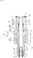
- FIG. 1 to FIG. 8 The drawings only schematically show an example of the invention. They may have a mismatch to each other due to different maginification in each direction. Each element denoted by a symbol is only an example.
- a machine tool 1 comprises a rotating unit U1, a supporting unit U2, ant a fluid supplying unit U3.
- the rotating unit U1 includes a spindle (a sub spindle 52, for example) provided with a chucking unit 60 for releasably chucking a workpiece W1.
- the supporting unit U2 rotatably supports the sub spindle 52 around a spindle axis AX1.
- the fluid supplying unit U3 is removably mounted on the supporting unit U2 to supply fluid to the chucking unit 60 via the sub spindle 52.
- the fluid supplying unit U3 has an insert P1 to be received in the rotating unit U1 in the direction of the spindle axis (the Z-axis direction).
- the rotating unit U1 has an inner circumferential surface U1i opposite an outer circumferential surface P1o of the insert P1.
- a labyrinth clearance C1 is formed between the outer circumferential surface P1o of the insert P1 and the inner circumferential surface U1i of the rotating unit U1.
- the labyrinth clearance C1 allows rotation of the rotating unit U1 and restricts leak of fluid from the sub spindle 52 when the rotating unit U1 is rotated.
- the rotating unit U1 in a state that the fluid supplying unit U3 is mounted on the supporting unit U2, the rotating unit U1 is rotatable with respect to the fluid supplying unit U3 and the labyrinth clearance C1 formed between the outer circumferential surface P1o of the insert P1 and the inner circumferential surface U1i of the rotating unit U1 to restrict leak of fluid from the sub spindle 52 when the rotating unit U1 is rotated.
- the embodiment provides a machine tool capable of facilitating a process of mounting the fluid supplying unit to the supporting unit which rotatably supports the spindle.
- the spindle is not limited to the sub spindle and may be a main spindle.
- the chucking unit comprises various chucking means for holding the workpiece such as a collet and claw.
- the fluid comprises liquid and gas such as blow oil and blow air.
- the workpiece comprises a product.
- the labyrinth clearance comprises a clearance where a labyrinth phenomenon is observed due to rotation of the rotating unit and a clearance where a seal effect is generated.
- the labyrinth clearance may be a clearance fit in accordance with ISO (International Organization for Standardization) 286-2:2010 and JIS (Japanese Industrial Standard) B0401-2:2016; "Geometrical product specifications (GPS) -- ISO code system for tolerances on linear sizes -- Part 2: Tables of standard tolerance classes and limit deviations for holes and shafts".
- ISO International Organization for Standardization
- JIS Japanese Industrial Standard
- GPS Geographical product specifications
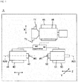
- FIG. 1 schematically shows an example of configuration of the machine tool.
- the machine tool 1 comprises an NC apparatus 80, a headstock 41 mounted on a stationary base 40, a backworking unit 51 mounted on a stationary base 50, and a tool post 46 mounted on a stationary base 45.
- the NC apparatus 80 controls the headstock 41, the backworking unit 51, and the tool post 46.
- the backworking unit 51 is movable in the Z-axis direction along the spindle axis AX1 and in a Y-axis direction perpendicular to the Z-axis direction.
- the NC apparatus 80 controls the Z-axis position and the Y-axis position of the backworking unit 51 via a not-shown driving unit thereof.
- the backworking unit 51 is provided with the sub spindle 52.
- the sub spindle 52 releasably chucks the workpiece W1 whose front face has been machined.
- the workpiece W1 is rotated by the sub spindle 52 on the spindle axis AX1.
- the sub spindle 52 is called an opposite spindle since it is opposite the main spindle 42.
- the Y-axis direction may be the horizontal direction in the embodiment but not limited thereto.
- the tool post 46 has a plurality of tools T1 for machining the workpiece W0, W1 attached thereto.
- the tool post 46 is movable in an X-axis direction perpendicular to the Z-axis direction and the Y-axis direction.
- the NC apparatus 80 controls the X-axis position of the tool post 46 via a not-shown driving unit thereof.
- the X-axis direction may be the vertical direction in the embodiment but not limited thereto.
- the tool post may be a turret tool post or a gang tool post. Various types of tool posts are available.
- the moving direction of the headstock 41, the backworking unit 51, and the tool post 46 is not limited to the direction as shown in FIG. 1 .
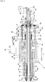
- the sub spindle 52 has a through-hole along the spindle axis AX1.
- the sub spindle 52 is rotatably attached to a body 21 of the supporting unit U2 via a bearing B1.
- the sub spindle 52 is provided with a chuck sleeve 63 and a push sleeve 65 inserted in the Z-axis direction (the direction of the spindle axis).
- a sleeve nut N1 for the product ejector 70 is removably attached to the chuck sleeve 63.
- the sleeve nut N1, the chuck sleeve 63, and the push sleeve 65 each has a through-hole along the spindle axis AX1 through which the product ejector 70 is inserted in the Z-axis direction.
- the sub spindle 52 along with the chuck sleeve 63 and the push sleeve 65 is rotated on the spindle axis AX1 around the product ejector 70.
- a built-in motor 55 is mounted around the sub spindle 52, comprising a stator 56 on the side of the supporting unit body 21 and a rotor 57 on the side of the sub spindle 52.
- the sub spindle 52 is driven by the motor 55 under control of the NC apparatus 80.
- the chucking unit 60 comprises a collet 61, a cap 62, and a collet open/close mechanism 63 to 69.
- the chucking unit 60 chucks the workpiece W1 inserted in the sub spindle 52 and releases it after the back face of the workpiece W1 is machined.
- the collet 61 is attached to the front end of the sub spindle 52 to releasably chuck the workpiece W1 supplied from the headstock 41.
- the collet 61 is rotated along with the sub spindle 52.
- the collet 61 is provided with a taper part 61a made gradually thinner toward the rear.
- the taper part 61a has a slit at a plurality of spots (three spots, for example).
- the cap 62 is attached to the front end of the sub spindle 52 to hold the collet 61.
- the collet open/close mechanism comprises the chuck sleeve 63, a coil spring 64 for opening the collet, the push sleeve 65, a claw 66, a shifter 67, a shifter lever 68, and an actuator 69 for opening/closing the collet.
- the chuck sleeve 63 is in contact with the taper part 61a of the collet 61 and slidabe in the Z-axis direction.
- the spring 64 is suspended on the collet 61 at the side of an advancing direction D2 thereof while on the inner circumferential surface of the chuck sleeve 63 at the side of a retracting direction D3 thereof.
- the spring 64 thereby urges the chuck sleeve 63 toward the retracting direction D3.
- the advancing direction D2 is a direction in which the workpiece W1 is pushed out toward the front side of the sub spindle 52 along the Z-axis direction.
- the retracting direction D3 is opposite the advancing direction D2.
- the push sleeve 65 is in contact with the rear end of the chuck sleeve 63 and slidabe in the Z-axis direction.
- the claw 66 has a distal end 66a, a base 66b, and a shaft 66c. The distal end 66a is in contact with a taper part 67a of the shifter 67.
- the claw 66 When the shifter 67 slides in the retracting direction D3 via the shifter lever 68 by the actuator 69, the claw 66 is rotated so that the distal end 66a thereof is moved away from the spindle axis AX1.
- the chuck sleeve 63 then slides in the advancing direction D2 via the push sleeve 65 by the base 66b of the claw 66.
- the collet 61 is then closed to chuck the workpiece W1.
- the shifter 67 slides in the advancing direction D2 via the shifter lever 68 by the actuator 69 the chuck sleeve 63 and the push sleeve 65 are retracted by urging force of the spring 64. Accordingly the claw 66 is rotated so that the distal end 66a thereof is moved toward the spindle axis AX1.
- the collet 61 is then opened to release the back-machined workpiece W1.
- the product ejector 70 is inserted inside the chuck sleeve 63 and the push sleeve 65 to be movable in the Z-axis direction.
- the product ejector 70 comprises a nearly cylindrical product ejecting shaft 72 and an ejection pin 74 removably attached to the front end of the ejecting shaft 72.
- the ejecting shaft 72 is provided with a through-hole 72c extended in the Z-axis direction.
- a coil spring 76 for ejecting a product (the workpiece W1) is suspended outside of the ejecting shaft 72.
- the spring 76 is compressed in the Z-axis direction to be suspended on a larger diameter portion 72b of the ejecting shaft 72 at the front end thereof while on a flange F1 of the rotating unit U1 at the rear end thereof.
- the workpiece W1 whose front face has been machined is inserted in the loosened collet 61 and chucked thereby.
- the back face of the workpiece W1 is machined and the collet 61 is opened.
- the product (the workpiece W1) is ejected toward the advancing direction D2 by urging force of the spring 76.
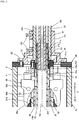
- the flange F1 is provided with a recess F1a for receiving the insert P1 of the fluid supplying unit U3.
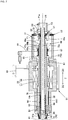
- the fluid supplying unit U3 removably attached to the rear end of the supporting unit U2 comprises a fluid pipe 31 for blow oil and blow air and an outer pipe 32 surrounding the fluid pipe 31.
- the fluid pipe 31 and the outer pipe 32 are arranged along the spindle axis AX1.
- the front end 31a of the fluid pipe 31 is inserted in the rear end of the ejecting shaft 72.
- the rear end 31b of the fluid pipe 31 is connected to an oil supplying unit 36 and a pressure air supplying unit 37 to selectively supply blow oil and blow air. Blow oil from the oil supplying unit 36 is supplied to the collet 61 via the fluid pipe 31 and the through-hole 72c of the ejecting shaft 72. Cut chips are thereby removed.
- Blow air from the pressure air supplying unit 37 is supplied to the collet 61 via the fluid pipe 31 and the through-hole 72c of the ejecting shaft 72. Cut chips are thereby removed.
- the outer periphery of the outer pipe 32 is held by a stop ring 32s in contact with the rear end of the flange F2.
- the outer pipe 32 is inserted in the flange F2 of the supporting unit U2 and fastened thereto by screws S3.
- the front end 32a of the fastened outer pipe 32 is inserted in the recess F1a of the flange F1 of the rotating unit U1. Accordingly, the front end 32a of the outer pipe 32 is an example of the insert P1 to be received in the rotating unit U1 in the Z-axis direction.
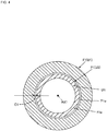
- FIG. 4 is an expanded section view of the insert P1 of the fluid supplying unit U3 and the flange F1 of the rotating unit U1. The other portions are not shown.
- the outer circumferential surface P1o of the insert P1 is circular in section shape.
- the inner circumferential surface U1i of the flange F1 is circular in section shape.
- the labyrinth clearance C1 is thereby formed between them.
- the outer circumferential surface P1o can be set at a reference value of -142 ⁇ m or more and a reference value of -80 ⁇ m or less in diameter.
- the inner circumferential surface U1i can be set at a reference value of +80 ⁇ m or more and a reference value of -142 ⁇ m or less in diameter. This is only an example.
- the labyrinth clearance C1 may be variously set as far as rotation of the rotating unit U1 is allowed and fluid leak from the sub spindle 52 is restricted when the rotating unit U1 is rotated.
- the outer circumferential surface P1o of the insert P1 and the inner circumferential surface U1i of the flange F1 are parallel to the spindle axis AX1 in a longitudinal section view along the spindle axis AX1.
- the labyrinth clearance C1 is formed along the spindle axis AX1. Accordingly, when the fluid supplying unit U3 is attached to the supporting unit U2, the labyrinth clearance C1 is formed only by inserting the insert P1 into the recess F1a of the flange F1 in the Z-axis direction, thereby eliminating the need of clearance adjustment work.
- blow oil in the through-hole 72c of the ejecting shaft 72 gradually flows in the retracting direction D3 along the outer periphery of the fluid pipe 31, flows in the advancing direction D2 between the outer periphery of the ejection shaft 72 and the inner periphery of the outer pipe 32, and finally leaks through between the flange F1 and the front end 32a of the outer pipe (including the labyrinth clearance C1). Blow air similarly flows.
- a labyrinth phenomenon is observed and a seal effect is generated at the labyrinth clearance C1. Leak of blow oil or blow air from the sub spindle 52 is thereby restricted.
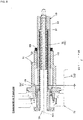
- FIG. 5 shows a longitudinal section view of the backworking unit on which the product passage pipe U4 is mounted.
- the passage pipe U4 is fastened to the flange F2 via a slit pipe U40.
- the passage pipe U4 is provided with a through-hole U4c through which the back-machined product (the workpiece W1) passes in the Z-axis direction to be ejected from the not-shown rear end thereof.
- the slit pipe U40 having a slit is outside the passage pipe U4 around the spindle axis AX1.
- the slit pipe U40 is tightened by the screws S3 of the flange F2 to fasten the passage pipe U4.
- a sleeve nut N2 for the passage pipe U4 is removably attached to the chuck sleeve 63 mounted on the front end of the sub spindle 52.
- the cap 62 is removed from the front end of the sub spindle 52.
- the collet 61, the spring 64 for opening the collet, and the chuck sleeve 63 along with the sleeve nut N2 are removed out of the through-hole along the spindle axis AX1.
- the sleeve nut N2 is removed from the chuck sleeve 63.
- the sleeve nut N1 for the product ejector is mounted on the chuck sleeve 63. Then, the flange f1 for the product ejector is fastened to the rear end of the sub spindle 52 by the screw S1.
- the spring 76 for ejecting a product and the push sleeve 65 are inserted in the through-hole of the sub spindle 52 and the flange F1 along the spindle axis AX1.
- the collet 61, the spring 64, and the chuck sleeve 63 along with the sleeve nut N1 are inserted in the through-hole of the sub spindle 52 along the spindle axis AX1.
- the cap 62 is attached to the front end of the sub spindle 52.
- the flange F2 is fastened to the supporting unit body 21 of the supporting unit U2 by the screw S2 as shown in FIG. 7 .
- the outer pipe 32 along with the fluid pipe 31 is inserted into the flange F2 in the advancing direction D2 until the stop ring 32s hits the flange F2.
- the outer pipe 32 is fastened to the flange F2 by the screws S3.
- the front end of the fluid pipe 31 is inserted into the through-hole 72c of the ejecting shaft 72 and the labyrinth clearance C1 is thereby formed between the outer circumferential surface P1o of the insert P1 and the inner circumferential surface U1i of the flange F1.
- FIG. 8 is a longitudinal section view of a comparative example of a backworking unit where a fluid supplying unit is mounted.
- an outer pipe 92 along with a fluid pipe 91 is inserted in the flange F2 in the advancing direction D2 until comes to the flange F1 of the rotating unit U1.
- the front end of the fluid pipe 91 is inserted in the through-hole 72c of the ejecting shaft 72 and the fluid supplying unit U9 comprising the fluid pipe 91 and the outer pipe 92 is mounted on the stationary flange F2.
- the clearance C9 is necessarily provided between the front end of the outer pipe 92 and the rear end of the flange F1.
- a wider clearance would leak more fluid, resulting in less oil or less air supplied to the collet and deficient removal of cut chips.
- a narrower clearance would cause an interference of the flange F1 of the rotating unit U1 with the stationary outer pipe 92 due to thermal expansion of the spindle.
- the clearance C9 is formed inside the backworking unit 51 and therefore not visually checked by using a measuring tool. Clearance is therefore provided in the following manner.
- a nut N9 engaged with the outer periphery of the outer pipe 92 is turned until comes to the flange F2. With the nut N9 pressed against the flange F2, the outer pipe 92 is turned counterclockwise by for example 1/4 round corresponding to a clearance of 0.25 mm. The nut N9 is fastened. Then the outer pipe 92 is fastened to the flange F2 by a screw S9. In this manner, the clearance C9 (0.25 mm for example) is formed between the stationary outer pipe 92 and the flange F1 of the rotating unit U1.
- the clearance C9 is not visually checked by using a measuding tool. It is difficult for an inexperienced operator to adjust the clearance C9 to a constant value. It causes an increase in parts replacement man-hours and work time. A wider clearance unintentionally adjusted would leak more blow oil and more blow air. Leak amount is varied according to operators.
- the embodiment of the invention eliminates such clearance adjustment process.
- the labyrinth clearance C1 is formed only by bringing the insert P1 into the recess F1a of the flange F1 in the Z-axis direction when the fluid supplying unit U3 is mounted on the supporting unit U2. Accordingly, the embodiment facilitates a process of mounting the fluid supplying unit to the supporting unit which rotatably supports the spindle. Further, parts replacement man-hours is reduced. Variation in leak amount due to different operators is prevented.
- the invention may be embodied in various ways.
- the invention is applied to the headstock where the fluid supplying unit is removably mounted.
- the invention provides a machine tool capable of facilitating the process of mounting the fluid supplying unit to the supporting unit for rotatably supporting the spindle.
- a fundamental effect as above described is also available from any technology only consisting of the elements of the independent claim.
- the invention covers any mutually replaced or modified configuration in the embodiments or prior art.
Landscapes
- Engineering & Computer Science (AREA)
- Mechanical Engineering (AREA)
- General Engineering & Computer Science (AREA)
- Turning (AREA)
- Gripping On Spindles (AREA)
Applications Claiming Priority (1)
| Application Number | Priority Date | Filing Date | Title |
|---|---|---|---|
| JP2017047990A JP6892594B2 (ja) | 2017-03-14 | 2017-03-14 | 工作機械 |
Publications (2)
| Publication Number | Publication Date |
|---|---|
| EP3375565A1 true EP3375565A1 (de) | 2018-09-19 |
| EP3375565B1 EP3375565B1 (de) | 2024-09-18 |
Family
ID=61074398
Family Applications (1)
| Application Number | Title | Priority Date | Filing Date |
|---|---|---|---|
| EP18153882.8A Active EP3375565B1 (de) | 2017-03-14 | 2018-01-29 | Maschinenwerkzeug |
Country Status (6)
| Country | Link |
|---|---|
| US (1) | US10226845B2 (de) |
| EP (1) | EP3375565B1 (de) |
| JP (1) | JP6892594B2 (de) |
| KR (1) | KR102431594B1 (de) |
| CN (1) | CN108568535B (de) |
| TW (1) | TWI746796B (de) |
Cited By (2)
| Publication number | Priority date | Publication date | Assignee | Title |
|---|---|---|---|---|
| EP3715027A4 (de) * | 2018-01-16 | 2021-08-25 | Star Micronics Co., Ltd. | Drehbank |
| EP3878584A4 (de) * | 2018-12-17 | 2022-08-24 | Star Micronics Co., Ltd. | Drehbank |
Families Citing this family (3)
| Publication number | Priority date | Publication date | Assignee | Title |
|---|---|---|---|---|
| US20190128421A1 (en) * | 2017-10-26 | 2019-05-02 | Royal Precision Tools Corporation | Gas-curtain protection device for aerospace precision machining spindle |
| JP7104328B2 (ja) | 2018-12-17 | 2022-07-21 | スター精密株式会社 | 旋盤 |
| JP7197781B2 (ja) * | 2018-12-17 | 2022-12-28 | スター精密株式会社 | 旋盤 |
Citations (4)
| Publication number | Priority date | Publication date | Assignee | Title |
|---|---|---|---|---|
| EP0467038A2 (de) * | 1990-07-18 | 1992-01-22 | Hellmerich Werkzeugmaschinen Ges.m.b.H. | Spindelkopfspeisung mit Sogeffekt |
| JPH04210307A (ja) * | 1990-12-13 | 1992-07-31 | Hitachi Seiko Ltd | スピンドルとチャック開閉駆動部の接続装置 |
| EP0978350A1 (de) * | 1998-01-23 | 2000-02-09 | Horkos Corp | Vorrichtung für die hauptspindel einer werkzeugmaschine und mehrspindelkopf für werkzeugmaschinen |
| JP2009172725A (ja) | 2008-01-25 | 2009-08-06 | Star Micronics Co Ltd | 工作機械 |
Family Cites Families (27)
| Publication number | Priority date | Publication date | Assignee | Title |
|---|---|---|---|---|
| US3611847A (en) * | 1959-12-07 | 1971-10-12 | Forsheda Gummifabrik Ab | Method of making a seal for relatively rotatable parts |
| US4117750A (en) * | 1977-04-19 | 1978-10-03 | Fridrikh Lvovich Kopelev | Spindle assembly for a precision machine tool |
| JPS5986901U (ja) * | 1982-11-29 | 1984-06-12 | 株式会社大隈鐵工所 | 回転継手内蔵の主軸台 |
| JPS62130265U (de) * | 1986-02-10 | 1987-08-17 | ||
| JP2521566B2 (ja) * | 1990-06-27 | 1996-08-07 | オークマ株式会社 | 主軸冷却用フアン付高速主軸頭 |
| JPH05304U (ja) * | 1991-06-19 | 1993-01-08 | 日立精機株式会社 | チヤツクにおける軸線方向位置決め装置 |
| DE4122545A1 (de) * | 1991-07-08 | 1993-01-14 | Gildemeister Ag | Werkstueckspindel einer drehmaschine |
| JPH0818220B2 (ja) * | 1991-07-12 | 1996-02-28 | オークマ株式会社 | 非接触回転シールの防水防塵方法 |
| JPH06106447A (ja) * | 1992-09-28 | 1994-04-19 | Citizen Watch Co Ltd | 工作機械の冷却方法及び工作機械 |
| US6389939B1 (en) * | 1994-08-26 | 2002-05-21 | Devlieg Bullard Ii, Inc. | Multiple-spindle bar machine |
| FR2734190B1 (fr) * | 1995-05-15 | 1997-06-20 | Kodak Pathe | Pointe tournante haute precision |
| JP3106291B2 (ja) * | 1996-01-30 | 2000-11-06 | オークマ株式会社 | 棒材切断機能付数値制御工作機械 |
| JPH11207566A (ja) * | 1998-01-23 | 1999-08-03 | Hookosu Kk | 自動工具交換装置付工作機械の主軸装置 |
| JP2000015535A (ja) * | 1998-07-01 | 2000-01-18 | Takahashi Kikai:Kk | 被加工物吸着保持装置 |
| JP2002263982A (ja) * | 2001-03-14 | 2002-09-17 | Brother Ind Ltd | 工作機械用主軸装置におけるシール装置 |
| JP2004306157A (ja) * | 2003-04-02 | 2004-11-04 | Brother Ind Ltd | 工作機械用主軸装置 |
| JP2005271177A (ja) * | 2004-03-26 | 2005-10-06 | Brother Ind Ltd | 工作機械用主軸装置 |
| DE202004017883U1 (de) * | 2004-11-18 | 2006-03-23 | Weha - Ludwig Werwein Gmbh | Buchse zur Aufnahme eines Werkzeugs |
| JP4611833B2 (ja) * | 2005-07-27 | 2011-01-12 | アイシン高丘株式会社 | 差動ケースの内面加工方法及び内面加工装置 |
| US20070169596A1 (en) * | 2006-01-20 | 2007-07-26 | Aerotech, Inc. | Collet chuck for direct drive rotary stage |
| JP4210307B2 (ja) * | 2007-01-29 | 2009-01-14 | ファナック株式会社 | 切粉排出構造を有する工作機械 |
| JP5104512B2 (ja) * | 2008-04-18 | 2012-12-19 | 株式会社ジェイテクト | 主軸装置 |
| US9592556B2 (en) * | 2012-03-30 | 2017-03-14 | Citizen Machinery Co., Ltd. | Processing machine |
| JP5801251B2 (ja) * | 2012-05-17 | 2015-10-28 | シチズンマシナリー株式会社 | 加工装置 |
| DE102013012765B4 (de) * | 2013-07-30 | 2025-07-03 | Schuster Maschinenbau Gmbh | Spindeleinheit für eine Bearbeitungseinrichtung mit einer Spindelarretierung |
| CN105108549B (zh) * | 2015-09-21 | 2017-09-29 | 江苏港星方能超声洗净科技有限公司 | 机床换刀装置 |
| TWI573944B (zh) * | 2015-12-25 | 2017-03-11 | Machining machine spindle and spindle seal |
-
2017
- 2017-03-14 JP JP2017047990A patent/JP6892594B2/ja active Active
-
2018
- 2018-01-11 US US15/869,006 patent/US10226845B2/en active Active
- 2018-01-16 KR KR1020180005545A patent/KR102431594B1/ko active Active
- 2018-01-29 EP EP18153882.8A patent/EP3375565B1/de active Active
- 2018-02-09 TW TW107104669A patent/TWI746796B/zh active
- 2018-02-09 CN CN201810135134.2A patent/CN108568535B/zh active Active
Patent Citations (4)
| Publication number | Priority date | Publication date | Assignee | Title |
|---|---|---|---|---|
| EP0467038A2 (de) * | 1990-07-18 | 1992-01-22 | Hellmerich Werkzeugmaschinen Ges.m.b.H. | Spindelkopfspeisung mit Sogeffekt |
| JPH04210307A (ja) * | 1990-12-13 | 1992-07-31 | Hitachi Seiko Ltd | スピンドルとチャック開閉駆動部の接続装置 |
| EP0978350A1 (de) * | 1998-01-23 | 2000-02-09 | Horkos Corp | Vorrichtung für die hauptspindel einer werkzeugmaschine und mehrspindelkopf für werkzeugmaschinen |
| JP2009172725A (ja) | 2008-01-25 | 2009-08-06 | Star Micronics Co Ltd | 工作機械 |
Cited By (4)
| Publication number | Priority date | Publication date | Assignee | Title |
|---|---|---|---|---|
| EP3715027A4 (de) * | 2018-01-16 | 2021-08-25 | Star Micronics Co., Ltd. | Drehbank |
| US11491555B2 (en) | 2018-01-16 | 2022-11-08 | Star Micronics Co., Ltd. | Lathe |
| EP3878584A4 (de) * | 2018-12-17 | 2022-08-24 | Star Micronics Co., Ltd. | Drehbank |
| US12257636B2 (en) | 2018-12-17 | 2025-03-25 | Star Micronics Co., Ltd. | Lathe with chuck |
Also Published As
| Publication number | Publication date |
|---|---|
| KR102431594B1 (ko) | 2022-08-10 |
| EP3375565B1 (de) | 2024-09-18 |
| US20180264610A1 (en) | 2018-09-20 |
| KR20180105059A (ko) | 2018-09-27 |
| CN108568535A (zh) | 2018-09-25 |
| CN108568535B (zh) | 2021-02-19 |
| TW201832849A (zh) | 2018-09-16 |
| JP2018149644A (ja) | 2018-09-27 |
| US10226845B2 (en) | 2019-03-12 |
| TWI746796B (zh) | 2021-11-21 |
| JP6892594B2 (ja) | 2021-06-23 |
Similar Documents
| Publication | Publication Date | Title |
|---|---|---|
| EP3375565B1 (de) | Maschinenwerkzeug | |
| EP2025439B1 (de) | Ausrichten eines Maschinenwerkzeugs mit einem Zielort auf einer Struktur | |
| EP3375563B1 (de) | Werkzeugmaschine | |
| US11919095B2 (en) | Lathe | |
| CN114630722B (zh) | 刀具夹紧装置和机床 | |
| JPH04275847A (ja) | 工作機械 | |
| EP4023376A1 (de) | Schneidwerkzeugauflage und werkzeugmaschine | |
| US20240416426A1 (en) | Tool Rest and Machine Tool | |
| GB1601010A (en) | Machine tool having a cleaning means | |
| JP6758477B2 (ja) | 工作機械の主軸装置 | |
| JP2001179512A (ja) | 筒状ワークの内径及び両端面の加工装置、筒状ワーク把持用チャック | |
| JPH08197311A (ja) | 多軸自動旋盤のクーラント供給装置 | |
| JP2005161500A (ja) | 穴加工装置 |
Legal Events
| Date | Code | Title | Description |
|---|---|---|---|
| PUAI | Public reference made under article 153(3) epc to a published international application that has entered the european phase |
Free format text: ORIGINAL CODE: 0009012 |
|
| STAA | Information on the status of an ep patent application or granted ep patent |
Free format text: STATUS: THE APPLICATION HAS BEEN PUBLISHED |
|
| AK | Designated contracting states |
Kind code of ref document: A1 Designated state(s): AL AT BE BG CH CY CZ DE DK EE ES FI FR GB GR HR HU IE IS IT LI LT LU LV MC MK MT NL NO PL PT RO RS SE SI SK SM TR |
|
| AX | Request for extension of the european patent |
Extension state: BA ME |
|
| STAA | Information on the status of an ep patent application or granted ep patent |
Free format text: STATUS: REQUEST FOR EXAMINATION WAS MADE |
|
| 17P | Request for examination filed |
Effective date: 20190319 |
|
| RBV | Designated contracting states (corrected) |
Designated state(s): AL AT BE BG CH CY CZ DE DK EE ES FI FR GB GR HR HU IE IS IT LI LT LU LV MC MK MT NL NO PL PT RO RS SE SI SK SM TR |
|
| STAA | Information on the status of an ep patent application or granted ep patent |
Free format text: STATUS: EXAMINATION IS IN PROGRESS |
|
| 17Q | First examination report despatched |
Effective date: 20211118 |
|
| REG | Reference to a national code |
Ref country code: DE Free format text: PREVIOUS MAIN CLASS: B23Q0011100000 Ref country code: DE Ref legal event code: R079 Ref document number: 602018074435 Country of ref document: DE Free format text: PREVIOUS MAIN CLASS: B23Q0011100000 Ipc: B23B0031200000 |
|
| RIC1 | Information provided on ipc code assigned before grant |
Ipc: B23B 31/20 20060101AFI20240416BHEP |
|
| GRAP | Despatch of communication of intention to grant a patent |
Free format text: ORIGINAL CODE: EPIDOSNIGR1 |
|
| STAA | Information on the status of an ep patent application or granted ep patent |
Free format text: STATUS: GRANT OF PATENT IS INTENDED |
|
| INTG | Intention to grant announced |
Effective date: 20240524 |
|
| GRAS | Grant fee paid |
Free format text: ORIGINAL CODE: EPIDOSNIGR3 |
|
| GRAA | (expected) grant |
Free format text: ORIGINAL CODE: 0009210 |
|
| STAA | Information on the status of an ep patent application or granted ep patent |
Free format text: STATUS: THE PATENT HAS BEEN GRANTED |
|
| AK | Designated contracting states |
Kind code of ref document: B1 Designated state(s): AL AT BE BG CH CY CZ DE DK EE ES FI FR GB GR HR HU IE IS IT LI LT LU LV MC MK MT NL NO PL PT RO RS SE SI SK SM TR |
|
| REG | Reference to a national code |
Ref country code: GB Ref legal event code: FG4D |
|
| REG | Reference to a national code |
Ref country code: CH Ref legal event code: EP |
|
| REG | Reference to a national code |
Ref country code: IE Ref legal event code: FG4D |
|
| REG | Reference to a national code |
Ref country code: DE Ref legal event code: R096 Ref document number: 602018074435 Country of ref document: DE |
|
| REG | Reference to a national code |
Ref country code: LT Ref legal event code: MG9D |
|
| PG25 | Lapsed in a contracting state [announced via postgrant information from national office to epo] |
Ref country code: NO Free format text: LAPSE BECAUSE OF FAILURE TO SUBMIT A TRANSLATION OF THE DESCRIPTION OR TO PAY THE FEE WITHIN THE PRESCRIBED TIME-LIMIT Effective date: 20241218 |
|
| PG25 | Lapsed in a contracting state [announced via postgrant information from national office to epo] |
Ref country code: GR Free format text: LAPSE BECAUSE OF FAILURE TO SUBMIT A TRANSLATION OF THE DESCRIPTION OR TO PAY THE FEE WITHIN THE PRESCRIBED TIME-LIMIT Effective date: 20241219 Ref country code: FI Free format text: LAPSE BECAUSE OF FAILURE TO SUBMIT A TRANSLATION OF THE DESCRIPTION OR TO PAY THE FEE WITHIN THE PRESCRIBED TIME-LIMIT Effective date: 20240918 |
|
| PG25 | Lapsed in a contracting state [announced via postgrant information from national office to epo] |
Ref country code: BG Free format text: LAPSE BECAUSE OF FAILURE TO SUBMIT A TRANSLATION OF THE DESCRIPTION OR TO PAY THE FEE WITHIN THE PRESCRIBED TIME-LIMIT Effective date: 20240918 |
|
| PG25 | Lapsed in a contracting state [announced via postgrant information from national office to epo] |
Ref country code: LV Free format text: LAPSE BECAUSE OF FAILURE TO SUBMIT A TRANSLATION OF THE DESCRIPTION OR TO PAY THE FEE WITHIN THE PRESCRIBED TIME-LIMIT Effective date: 20240918 |
|
| PG25 | Lapsed in a contracting state [announced via postgrant information from national office to epo] |
Ref country code: HR Free format text: LAPSE BECAUSE OF FAILURE TO SUBMIT A TRANSLATION OF THE DESCRIPTION OR TO PAY THE FEE WITHIN THE PRESCRIBED TIME-LIMIT Effective date: 20240918 |
|
| REG | Reference to a national code |
Ref country code: NL Ref legal event code: MP Effective date: 20240918 |
|
| PG25 | Lapsed in a contracting state [announced via postgrant information from national office to epo] |
Ref country code: RS Free format text: LAPSE BECAUSE OF FAILURE TO SUBMIT A TRANSLATION OF THE DESCRIPTION OR TO PAY THE FEE WITHIN THE PRESCRIBED TIME-LIMIT Effective date: 20241218 |
|
| PG25 | Lapsed in a contracting state [announced via postgrant information from national office to epo] |
Ref country code: RS Free format text: LAPSE BECAUSE OF FAILURE TO SUBMIT A TRANSLATION OF THE DESCRIPTION OR TO PAY THE FEE WITHIN THE PRESCRIBED TIME-LIMIT Effective date: 20241218 Ref country code: NO Free format text: LAPSE BECAUSE OF FAILURE TO SUBMIT A TRANSLATION OF THE DESCRIPTION OR TO PAY THE FEE WITHIN THE PRESCRIBED TIME-LIMIT Effective date: 20241218 Ref country code: LV Free format text: LAPSE BECAUSE OF FAILURE TO SUBMIT A TRANSLATION OF THE DESCRIPTION OR TO PAY THE FEE WITHIN THE PRESCRIBED TIME-LIMIT Effective date: 20240918 Ref country code: HR Free format text: LAPSE BECAUSE OF FAILURE TO SUBMIT A TRANSLATION OF THE DESCRIPTION OR TO PAY THE FEE WITHIN THE PRESCRIBED TIME-LIMIT Effective date: 20240918 Ref country code: GR Free format text: LAPSE BECAUSE OF FAILURE TO SUBMIT A TRANSLATION OF THE DESCRIPTION OR TO PAY THE FEE WITHIN THE PRESCRIBED TIME-LIMIT Effective date: 20241219 Ref country code: FI Free format text: LAPSE BECAUSE OF FAILURE TO SUBMIT A TRANSLATION OF THE DESCRIPTION OR TO PAY THE FEE WITHIN THE PRESCRIBED TIME-LIMIT Effective date: 20240918 Ref country code: BG Free format text: LAPSE BECAUSE OF FAILURE TO SUBMIT A TRANSLATION OF THE DESCRIPTION OR TO PAY THE FEE WITHIN THE PRESCRIBED TIME-LIMIT Effective date: 20240918 |
|
| REG | Reference to a national code |
Ref country code: AT Ref legal event code: MK05 Ref document number: 1724263 Country of ref document: AT Kind code of ref document: T Effective date: 20240918 |
|
| PG25 | Lapsed in a contracting state [announced via postgrant information from national office to epo] |
Ref country code: NL Free format text: LAPSE BECAUSE OF FAILURE TO SUBMIT A TRANSLATION OF THE DESCRIPTION OR TO PAY THE FEE WITHIN THE PRESCRIBED TIME-LIMIT Effective date: 20240918 |
|
| PG25 | Lapsed in a contracting state [announced via postgrant information from national office to epo] |
Ref country code: IS Free format text: LAPSE BECAUSE OF FAILURE TO SUBMIT A TRANSLATION OF THE DESCRIPTION OR TO PAY THE FEE WITHIN THE PRESCRIBED TIME-LIMIT Effective date: 20250118 Ref country code: PT Free format text: LAPSE BECAUSE OF FAILURE TO SUBMIT A TRANSLATION OF THE DESCRIPTION OR TO PAY THE FEE WITHIN THE PRESCRIBED TIME-LIMIT Effective date: 20250120 |
|
| PG25 | Lapsed in a contracting state [announced via postgrant information from national office to epo] |
Ref country code: RO Free format text: LAPSE BECAUSE OF FAILURE TO SUBMIT A TRANSLATION OF THE DESCRIPTION OR TO PAY THE FEE WITHIN THE PRESCRIBED TIME-LIMIT Effective date: 20240918 Ref country code: SM Free format text: LAPSE BECAUSE OF FAILURE TO SUBMIT A TRANSLATION OF THE DESCRIPTION OR TO PAY THE FEE WITHIN THE PRESCRIBED TIME-LIMIT Effective date: 20240918 |
|
| PG25 | Lapsed in a contracting state [announced via postgrant information from national office to epo] |
Ref country code: ES Free format text: LAPSE BECAUSE OF FAILURE TO SUBMIT A TRANSLATION OF THE DESCRIPTION OR TO PAY THE FEE WITHIN THE PRESCRIBED TIME-LIMIT Effective date: 20240918 |
|
| PG25 | Lapsed in a contracting state [announced via postgrant information from national office to epo] |
Ref country code: AT Free format text: LAPSE BECAUSE OF FAILURE TO SUBMIT A TRANSLATION OF THE DESCRIPTION OR TO PAY THE FEE WITHIN THE PRESCRIBED TIME-LIMIT Effective date: 20240918 Ref country code: EE Free format text: LAPSE BECAUSE OF FAILURE TO SUBMIT A TRANSLATION OF THE DESCRIPTION OR TO PAY THE FEE WITHIN THE PRESCRIBED TIME-LIMIT Effective date: 20240918 |
|
| PG25 | Lapsed in a contracting state [announced via postgrant information from national office to epo] |
Ref country code: CZ Free format text: LAPSE BECAUSE OF FAILURE TO SUBMIT A TRANSLATION OF THE DESCRIPTION OR TO PAY THE FEE WITHIN THE PRESCRIBED TIME-LIMIT Effective date: 20240918 Ref country code: PL Free format text: LAPSE BECAUSE OF FAILURE TO SUBMIT A TRANSLATION OF THE DESCRIPTION OR TO PAY THE FEE WITHIN THE PRESCRIBED TIME-LIMIT Effective date: 20240918 |
|
| PG25 | Lapsed in a contracting state [announced via postgrant information from national office to epo] |
Ref country code: SK Free format text: LAPSE BECAUSE OF FAILURE TO SUBMIT A TRANSLATION OF THE DESCRIPTION OR TO PAY THE FEE WITHIN THE PRESCRIBED TIME-LIMIT Effective date: 20240918 |
|
| REG | Reference to a national code |
Ref country code: DE Ref legal event code: R097 Ref document number: 602018074435 Country of ref document: DE |
|
| PG25 | Lapsed in a contracting state [announced via postgrant information from national office to epo] |
Ref country code: DK Free format text: LAPSE BECAUSE OF FAILURE TO SUBMIT A TRANSLATION OF THE DESCRIPTION OR TO PAY THE FEE WITHIN THE PRESCRIBED TIME-LIMIT Effective date: 20240918 |
|
| PLBE | No opposition filed within time limit |
Free format text: ORIGINAL CODE: 0009261 |
|
| STAA | Information on the status of an ep patent application or granted ep patent |
Free format text: STATUS: NO OPPOSITION FILED WITHIN TIME LIMIT |
|
| 26N | No opposition filed |
Effective date: 20250619 |
|
| PG25 | Lapsed in a contracting state [announced via postgrant information from national office to epo] |
Ref country code: SE Free format text: LAPSE BECAUSE OF FAILURE TO SUBMIT A TRANSLATION OF THE DESCRIPTION OR TO PAY THE FEE WITHIN THE PRESCRIBED TIME-LIMIT Effective date: 20240918 |
|
| PG25 | Lapsed in a contracting state [announced via postgrant information from national office to epo] |
Ref country code: MC Free format text: LAPSE BECAUSE OF FAILURE TO SUBMIT A TRANSLATION OF THE DESCRIPTION OR TO PAY THE FEE WITHIN THE PRESCRIBED TIME-LIMIT Effective date: 20240918 Ref country code: LU Free format text: LAPSE BECAUSE OF NON-PAYMENT OF DUE FEES Effective date: 20250129 |
|
| PG25 | Lapsed in a contracting state [announced via postgrant information from national office to epo] |
Ref country code: BE Free format text: LAPSE BECAUSE OF NON-PAYMENT OF DUE FEES Effective date: 20250131 |
|
| REG | Reference to a national code |
Ref country code: BE Ref legal event code: MM Effective date: 20250131 |
|
| PGFP | Annual fee paid to national office [announced via postgrant information from national office to epo] |
Ref country code: GB Payment date: 20251211 Year of fee payment: 9 |
|
| PGFP | Annual fee paid to national office [announced via postgrant information from national office to epo] |
Ref country code: FR Payment date: 20251128 Year of fee payment: 9 |
|
| PG25 | Lapsed in a contracting state [announced via postgrant information from national office to epo] |
Ref country code: IE Free format text: LAPSE BECAUSE OF NON-PAYMENT OF DUE FEES Effective date: 20250129 |
|
| REG | Reference to a national code |
Ref country code: CH Ref legal event code: U11 Free format text: ST27 STATUS EVENT CODE: U-0-0-U10-U11 (AS PROVIDED BY THE NATIONAL OFFICE) Effective date: 20260201 |
|
| PGFP | Annual fee paid to national office [announced via postgrant information from national office to epo] |
Ref country code: DE Payment date: 20251203 Year of fee payment: 9 |
|
| PGFP | Annual fee paid to national office [announced via postgrant information from national office to epo] |
Ref country code: IT Payment date: 20251219 Year of fee payment: 9 |
|
| PGFP | Annual fee paid to national office [announced via postgrant information from national office to epo] |
Ref country code: TR Payment date: 20260128 Year of fee payment: 9 |
|
| PGFP | Annual fee paid to national office [announced via postgrant information from national office to epo] |
Ref country code: CH Payment date: 20260201 Year of fee payment: 9 |