EP3377232B1 - Dispositif d'application de revêtement et procédé d'application de revêtement correspondant - Google Patents
Dispositif d'application de revêtement et procédé d'application de revêtement correspondant Download PDFInfo
- Publication number
- EP3377232B1 EP3377232B1 EP16797749.5A EP16797749A EP3377232B1 EP 3377232 B1 EP3377232 B1 EP 3377232B1 EP 16797749 A EP16797749 A EP 16797749A EP 3377232 B1 EP3377232 B1 EP 3377232B1
- Authority
- EP
- European Patent Office
- Prior art keywords
- coating agent
- coating
- jets
- intercepting device
- agent jets
- Prior art date
- Legal status (The legal status is an assumption and is not a legal conclusion. Google has not performed a legal analysis and makes no representation as to the accuracy of the status listed.)
- Active
Links
Images


Classifications
-
- B—PERFORMING OPERATIONS; TRANSPORTING
- B05—SPRAYING OR ATOMISING IN GENERAL; APPLYING FLUENT MATERIALS TO SURFACES, IN GENERAL
- B05B—SPRAYING APPARATUS; ATOMISING APPARATUS; NOZZLES
- B05B14/00—Arrangements for collecting, re-using or eliminating excess spraying material
-
- B—PERFORMING OPERATIONS; TRANSPORTING
- B05—SPRAYING OR ATOMISING IN GENERAL; APPLYING FLUENT MATERIALS TO SURFACES, IN GENERAL
- B05B—SPRAYING APPARATUS; ATOMISING APPARATUS; NOZZLES
- B05B12/00—Arrangements for controlling delivery; Arrangements for controlling the spray area
- B05B12/16—Arrangements for controlling delivery; Arrangements for controlling the spray area for controlling the spray area
- B05B12/20—Masking elements, i.e. elements defining uncoated areas on an object to be coated
- B05B12/22—Masking elements, i.e. elements defining uncoated areas on an object to be coated movable relative to the spray area
-
- B—PERFORMING OPERATIONS; TRANSPORTING
- B05—SPRAYING OR ATOMISING IN GENERAL; APPLYING FLUENT MATERIALS TO SURFACES, IN GENERAL
- B05B—SPRAYING APPARATUS; ATOMISING APPARATUS; NOZZLES
- B05B12/00—Arrangements for controlling delivery; Arrangements for controlling the spray area
- B05B12/16—Arrangements for controlling delivery; Arrangements for controlling the spray area for controlling the spray area
- B05B12/32—Shielding elements, i.e. elements preventing overspray from reaching areas other than the object to be sprayed
- B05B12/34—Shielding elements, i.e. elements preventing overspray from reaching areas other than the object to be sprayed movable relative to the spray area
-
- B—PERFORMING OPERATIONS; TRANSPORTING
- B05—SPRAYING OR ATOMISING IN GENERAL; APPLYING FLUENT MATERIALS TO SURFACES, IN GENERAL
- B05D—PROCESSES FOR APPLYING FLUENT MATERIALS TO SURFACES, IN GENERAL
- B05D1/00—Processes for applying liquids or other fluent materials
- B05D1/02—Processes for applying liquids or other fluent materials performed by spraying
-
- B—PERFORMING OPERATIONS; TRANSPORTING
- B05—SPRAYING OR ATOMISING IN GENERAL; APPLYING FLUENT MATERIALS TO SURFACES, IN GENERAL
- B05D—PROCESSES FOR APPLYING FLUENT MATERIALS TO SURFACES, IN GENERAL
- B05D1/00—Processes for applying liquids or other fluent materials
- B05D1/32—Processes for applying liquids or other fluent materials using means for protecting parts of a surface not to be coated, e.g. using stencils, resists
Definitions
- the invention relates to a coating device for coating a component with a coating agent, in particular for painting a motor vehicle body part or an aircraft component with a paint. Furthermore, the invention relates to a corresponding coating method.
- a sharp-edged coating or painting is also advantageous in particular in the case of a contrasting painting of motor vehicles if different surface areas of the motor vehicle body are to be painted with different colors.
- the sharp-edged painting with the above-mentioned application devices and methods makes it possible to dispense with masking the surface areas of the motor vehicle body that are not to be painted, as is the case with contrast painting with rotary atomizers is usually required.
- JP S57 24663 A a conventional rotary atomizer arrangement.
- the invention is therefore based on the object of creating a correspondingly improved coating device or a correspondingly improved coating method.
- the invention is based on the newly gained technical-physical Realization that the spatters on the component surface are caused by unsteady processes when the coating medium jet is switched on or off.
- the coating medium jet When the coating medium jet is switched on, it takes a certain amount of time before the coating medium jet has assumed its stationary state. Immediately after switching on, the jet of coating medium is still unsteady, which can lead to disruptive spatter when it hits the surface of the component. Similar non-stationary processes also occur when the coating medium jet is switched off, so that the coating medium jet is non-stationary immediately before the end of coating, which can again lead to an unsatisfactory coating result.
- the invention therefore includes the general technical teaching not to use the coating medium jet, which is unsteady due to switching processes, for coating the component. It is true that the unsteady processes of the coating medium jet when switching on or off cannot be prevented, since this is unavoidable. However, there is the possibility of discarding the jet of coating medium if it is still non-stationary due to switching processes. Within the scope of the invention, the coating medium jet is therefore only used for coating during stationary states, whereas the coating medium jet is not used for coating during transient processes when switching on or off.
- the coating device initially has an applicator which emits a plurality of parallel coating agent jets of the coating agent onto the component.
- the applicator can be designed and function, for example, in such a way the patent applications cited at the outset DE 10 2013 002 433 A1 , DE 10 2013 002 413 A1 , DE 10 2013 002 412 A1 and DE 10 2013 002 411 A1 is described.
- the jet of coating medium is a spatially narrowly delimited jet of droplets or a spatially delimited coherent jet.
- the coating device according to the invention is distinguished by a collecting device which, in an active position, collects the jet of coating agent between the applicator and the component, so that the jet of coating agent does not then impinge on the component.
- the collecting device thus makes it possible to collect the jet of coating agent when it is still in an unsteady state, such as when it is switched on or switched off.
- the collecting device can prevent the jet of coating medium from hitting the component in the unsteady state, since in the worst case this could lead to undesired spattering on the component surface.
- the catching device can preferably be adjusted between the already mentioned active position and an inactive position, with the catching device letting the coating medium jet through in the inactive position, so that the coating medium jet can then hit the component unhindered.
- the collecting device In the settled, stationary state of the coating medium jet, the collecting device is thus moved into the inactive position, so that the stationary coating medium jet can then hit the component surface unhindered.
- the collecting device In the non-stationary state of the coating medium jet (e.g. immediately after a switching operation), on the other hand, the collecting device is moved into the active position and then catches the non-stationary coating medium jet so that it cannot hit the component.
- the movement of the catcher between the active position and the inactive position can be a pure linear movement, for example.
- the movement of the collecting device between the active position and the inactive position is a pure rotary movement.
- the movement of the collecting device can also be a folding movement.
- the movement of the collecting device between the active position and the inactive position is a combined sliding, folding and/or rotating movement.
- the axis of rotation is preferably aligned parallel to the jet of coating agent and/or at right angles to the surface of the component to be coated.
- the collecting device is preferably mounted on a rotatable unit and can follow the rotation of the applicator.
- the folding movement takes place about a pivot axis which is preferably aligned at right angles to the coating medium jet and/or parallel to the surface of the component to be coated is.
- the coating device also comprises at least one actuator for moving the catcher between the active position and the inactive position.
- the actuator can have an electric motor, for example, in order to adjust the collecting device.
- the actuator works pneumatically or hydraulically.
- the actuator works electromagnetically.
- the invention is not limited to the examples mentioned above with regard to the drive principle of the actuator.
- the direction of movement of the collecting device can correspond to the direction of movement of the applicator and/or be opposite to it.
- the direction of movement of the collecting device can be angled at an angle of 0°-180°, in particular 30°-150°, in particular 45°-135° to the direction of movement of the applicator and/or to the direction of the at least one jet.
- the catching device can be moved as quickly as possible between the inactive position and the active position in order to achieve a rapid response behavior of the catching device.
- the maximum adjustment speed of the actuator is therefore preferably significantly greater than the exit speed of the jet of coating medium from the applicator or the flow speed in the jet of coating medium.
- the maximum adjustment speed of the The actuator can be greater by a factor of 1, 2, 5, 10, 25 or even 50 than the exit velocity or the flow velocity of the coating medium jet.
- the collecting device therefore requires a short switching time, which is relatively short in relation to the exit speed from the applicator. In addition, this switching time is also short in absolute terms.
- the switching time between the active position and the inactive position is preferably less than 500 ms, 250 ms, 100 ms, 50 ms, 25 ms, 10 ms, 5 ms, 2 ms or 1 ms.
- the collecting device preferably has at least one drain in order to discharge the collected coating agent through the drain when the collecting device is in the active position. This makes sense so that the collected coating agent does not get onto the component surface.
- This removal of the collected coating agent through the drain can be supported by at least one suction device being connected to the drain of the collecting device in order to suck off the coating agent collected by the collecting device through the drain.
- This suction device can, for example, generate a negative pressure in the drain in order to suck off the collected coating agent.
- the catcher works with at least one cutting edge, to cut off the jet of coating agent in the active position.
- the blade has a cutting edge that is transverse (e.g., perpendicular) to the jet of coating agent.
- the cutting edge is preferably movable relative to the jet of coating medium between the active position and the inactive position, in particular in a direction of displacement perpendicular to the cutting edge and perpendicular to the jet of coating medium.
- the cutting edge has a cutting edge surface facing the jet of coating medium, which encloses a specific cutting angle with the jet of coating medium, which can for example be in the range of 45°-90°, 70°-90° or 80°-90°.
- the cutting edge of the cutting edge has a wedge angle that is in the range of 45°-60°.
- the cutting edge has a blade angle that is in the range of 5°-30° (e.g. 10°-25°).
- the cutting edge can be coated with a wetting-inhibiting or wetting-promoting coating in order to allow any drops that may occur on the cutting edge during the cutting process to either bounce off in the cutting direction or to be able to absorb them on the side facing the jet in the cutting direction .
- the collecting device has at least two cutting edges, both of which can be moved between the inactive position and the active position, the cutting edges of the two cutting edges being arranged parallel to one another could be.
- the cutting edges can be arranged either on the same side or on opposite sides of the coating medium jet.
- the cutting edges can be moved independently of one another or are mechanically connected to one another, so that the cutting edges can then be moved synchronously together.
- the cutting edges with their cutting edge surface facing the coating medium jet can either shoot in the same cutting angle or different cutting angles with the coating medium jet.
- the cutting edges can optionally be movable in opposite directions or in the same direction in relation to the jet of coating medium.
- the cutting edges can be arranged either in the same axial position or in different axial positions in relation to the jet of coating medium.
- the cutting edges can optionally be attached to the collecting device so that they can be replaced or can be integrally formed on the collecting device.
- the collecting device has a collecting area in order to receive the coating agent, this collecting area preferably narrowing in a funnel shape towards the outflow.
- the collection area is preferably located on the side of the cutting edge facing away from the jet of coating medium.
- the collecting device has at least two cutting edges on the same side, there is advantageously an additional collecting area for the coating agent with a drain between the cutting edges.
- the cutting edge can have a straight (linear) shape like a razor blade, but it can also have a convex or concave or curved shape. In a special form, it is formed in the shape of a triangle.
- the cutting edge can also serve to at least partially close the collection area in the inactive position. This is advantageous if the collected coating agent is sucked out of the collecting area by a suction device, as has already been briefly described above.
- the at least partial closure of the collection area by the cutting edge increases the negative pressure used for suction, which makes the suction more effective.
- the foldable cutting edge should not completely close the collection area even in the inactive position. Rather, the foldable cutting edge should also leave a small gap open even in the inactive position, so that coating medium can then still be sucked in from the outside through the gap into the collection area can be.
- the collection device can have a fluid supply line in order to introduce a fluid into the collection device, such as a rinsing agent, a solvent or a diluent or air.
- a fluid such as a rinsing agent, a solvent or a diluent or air.
- the introduction of such a fluid can support and facilitate the removal of the collected coating agent through the drain.
- the fluid can be introduced into the collecting area via at least one nozzle, at least one slot or via a porous structure.
- the coating agent it should be mentioned that it is a paint, an adhesive, a sealant or an insulating material.
- this is preferably an applicator as in the patent applications cited at the outset DE 10 2013 002 433 A1 , DE 10 2013 002 413 A1 , DE 10 2013 002 412 A1 and DE 10 2013 002 411 A1 is described, so that the content of these patent applications of the present description is to be attributed in terms of structure and operation of the applicator in its entirety.
- the invention is particularly well suited for coating bodywork components (eg motor vehicle bodywork components), add-on parts for motor vehicles or components of the aviation industry.
- the applicator is preferably guided over the component by a multi-axis coating robot, in particular by a coating robot with serial kinematics.
- a coating robot with serial kinematics Such coating robots are known per se from the prior art and therefore do not need to be described in more detail.
- the applicator can also be guided over the component with another single or multi-axis movement device.
- the collecting device is preferably only deactivated when the transient processes after switching on the coating medium jet have subsided, so that the coating medium jet is only released from the collecting device and strikes the component surface when the transient processes after switching on have subsided are.
- the coating medium jet is switched off, the coating medium jet is preferably only switched off when the collecting device is activated, so that the unsteady shutdown processes of the coating medium jet can no longer impair the coating result.
- the Figures 1A and 1B show a coating device with an applicator 1, which emits a coherent jet of coating medium 2 onto a component 3.
- the applicator 1 can be an application device, for example, as described in the patent applications cited at the outset DE 10 2013 002 433 A1 , DE 10 2013 002 413 A1 , DE 10 2013 002 412 A1 and DE 10 2013 002 411 A1 is described, so that the content of these patent applications of the present description is to be attributed in terms of structure and operation of the applicator 1 in its entirety.
- the component 3 can be, for example, a motor vehicle body component that is to be painted with a contrasting finish, i. H. with different colors.
- the invention is not limited to automotive body components.
- the coating medium jet 2 is spatially limited here and can be switched on or off by the applicator 1, which enables sharp-edged painting.
- the coating device therefore prevents the coating medium jet 2 from impinging on the component 3 after a switching operation in the transient state. Points to this the coating device has a collecting device in order to collect the coating medium jet 2 if it still shows unsteady transitional states.
- This fall arrester is between an inactive position according to Figure 1A and according to an active position Figure 1B moveable.
- the collecting device lets the coating medium jet 2 through unhindered, so that the coating medium jet 2 can then impinge on the component 3.
- the collecting device catches the coating medium jet 2 and thereby prevents the coating medium jet 2 from being able to impinge on the component 3 .
- the collecting device has a cutting edge 4 which can be moved by an actuator 5 in the direction of the double arrow.
- the cutting edge 4 In the active position according to Figure 1B the cutting edge 4 has moved into the longitudinal axis of the coating medium jet 2 and thereby cuts off the coating medium jet 2 before it hits the component.
- the collected jet of coating medium then first reaches a funnel-shaped collecting area 6 in the collecting device and is then sucked off by a suction device 9 via a drain 7 and a discharge line 8 .
- a fluid supply 10 which is supplied with a fluid from a fluid source 12 via a fluid supply line 11 also opens into the collecting area 6 of the receiving device.
- the fluid source 12 thus conducts a fluid into the collecting area 6 via the fluid supply line 11 and the fluid supply 10, as a result of which the removal of the coating agent is facilitated by the drain 7.
- FIG. 2 shows a modification of the coating device according to FIG Figures 1A and 1B , so that, in order to avoid repetition, reference is made to the above description, the same reference numbers being used for corresponding details.
- a special feature of this coating device is that instead of the blade 4 according to the Figures 1A and 1B two cutting edges 4.1, 4.2 are provided.
- the two cutting edges 4.1, 4.2. are here arranged on the same side of the coating medium jet 2 and are moved by the actuator 5 together.
- figure 3 shows a modification of the coating device according to FIG figure 2 , so that to avoid repetition, reference is made to the above description.
- a special feature of this coating device is that the two cutting edges 4.1, 4.2 are arranged on opposite sides of the coating medium jet 2. Accordingly, two collecting areas 6.1, 6.2, two fluid feeds 10.1, 10.2, two fluid feed lines 11.1, 11.2, two drains 7.1, 7.2 and two suction lines 8.1, 8.2 are provided.
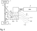
- FIG figure 4 shows a further modification of the coating device according to FIG figure 2 , so that, in order to avoid repetition, reference is made to the above description, the same reference numbers being used for corresponding details.
- a special feature of this coating device is that the cutting edge 4.1 encloses an angle of intersection ⁇ 1 with the jet of coating medium, while the other cutting edge 4.2 encloses an angle of intersection ⁇ 2 with the jet of coating medium 2.
- the two intersection angles ⁇ 1, ⁇ 2 are not shown as being the same here, but can also be the same in a further advantageous embodiment.
- Another special feature of this coating device is that the two cutters 4.1, 4.2 each feed their own separate funnel-shaped collecting area 6.1 or 6.2.
- FIG. 5 shows figure 5 a blade angle ⁇ between the side surface 13 of the cutting edge 4 facing the coating medium jet 2 and an opposite side surface 14
- Figures 5 and 6 a cutting edge 15 of the cutting edge 4, the cutting edge 15 running at right angles to the coating medium jet 2.
- figure 7 shows a modification of an applicator 1 according to the invention, which has a plurality of jets of coating medium from a plurality of nozzles 6 2 emits.
- the nozzles 16 are arranged in a line along an applicator nozzle axis rD .
- the coating agent jets 2, on the other hand, are aligned parallel to one another along a direction v B .
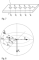
- figure 8 shows on the one hand that the applicator nozzle axis r D is aligned at right angles to the direction v B of the coating medium jets 2 .
- figure 8 shows figure 8 as vectors v A the direction of movement of blade 4 and as vector v S the direction of movement of blade 4. It can be seen from this representation that the direction of movement v A of applicator 1 is angled relative to the direction of movement v S of blade 4.
- figure 9 shows a modification of figure 8 , this modification showing a special case in which the direction of movement v S of the cutting edge 4 is aligned parallel to the direction of movement v A of the applicator 1 .
- a special feature of this example is that the cutting edge 4 can be pivoted in the direction of the double arrow about a pivot axis 17 between an active position ( Figure 10A ) and an inactive position ( Figure 10B ) is foldable.
- the pivot axis 17 is perpendicular to the coating medium jet 2 and parallel to the surface to be coated Component 3 aligned, ie the pivot axis 17 runs in Figures 10A and 10B perpendicular to the drawing plane.
- FIG 11 shows a modification of the example according to FIG Figures 10A and 10B , so that, in order to avoid repetition, reference is made to the above description, the same reference numbers being used for corresponding details.
- a special feature of this example is that the collection area 6 is connected to a suction device that can generate a negative pressure in the collection area 6 in order to be able to suck off residues of coating agent 18 .
- the collecting area is delimited on its upper side by a shutter cover 19 and on its underside by a base 20 .
- the collecting area 6 thus forms a suction channel between the shutter cover 19 and the base 20.
- the drawing shows the inactive position of the cutting edge 6 in which the jet of coating medium 2 is not caught but is allowed to pass through to the component 3 .
- the cutting edge 6 partially closes the front opening of the suction channel between the shutter cover 19 and the base 20 except for a narrow gap 21 . This advantageously increases the negative pressure in the collection area 6 when the coating agent residues 18 are sucked off.
- the gap 21 that remains free also makes it possible for residues of coating agent to be sucked into the collecting area 6 from the outside through the gap 21 that remains free.
Landscapes
- Coating Apparatus (AREA)
- Details Or Accessories Of Spraying Plant Or Apparatus (AREA)
- Application Of Or Painting With Fluid Materials (AREA)
Claims (17)
- Dispositif de revêtement pour le revêtement d'un composant (3), notamment d'un composant de carrosserie de véhicule automobile, d'une pièce rapportée pour un véhicule automobile ou d'un composant de l'industrie aéronautique, avec un produit de revêtement, notamment avec une peinture, un adhésif, un produit d'étanchéité ou une substance isolante, aveca) un applicateur (1), dans lequel l'applicateur (1) est conçu pour projeter une pluralité de jets de produit de revêtement parallèlement entre eux sur le composant (3),b) un dispositif de capture (4-12) qui est conçu pour capturer, dans une position active, les jets de produits de revêtement (2) entre l'applicateur (1) et le composant (3), de façon à ce que les jets de produit de revêtement (2) n'arrivent pas jusqu'au composant (3), dans lequel le dispositif de capture (4-12) comprend au moins un tranchant (4 ; 4.1, 4.2) afin de couper les jets de produits de revêtement (2) dans la position active, dans lequel le tranchant (4; 4.1, 4.2) présente une arête tranchante (15) qui s'étend transversalement par rapport aux jets de produit de revêtement (2),
caractérisé en ce quec) l'arête tranchante (15) du tranchant (4 ; 4.1, 4.2) présente un angle de coin (β) qui est de l'ordre de 45° à 60°, etd) le tranchant (4 ; 4.1, 4.2) présente un angle de lame (ε) qui est de l'ordre de 5° à 30°. - Dispositif de revêtement selon la revendication 1, caractérisé en ce que le dispositif de capture (4-12) est mobile entre la position active et une position inactive, dans lequel le dispositif de capture (4-12), dans la position inactive, laisse passer les jets de produit de revêtement (2), de façon à ce que les jets de produit de revêtement (2) puissent arrivent sans encombre jusqu'au composant (3).
- Dispositif de revêtement selon la revendication 2, caractérisé en ce que le dispositif de capture (4-12) peut être coulisser de manière linéaire et/ou peut être mis en rotation et/ou peut être plié entre la position active et la position inactive.
- Dispositif de revêtement selon la revendication 3,
caractérisé en ce quea) le dispositif de capture exécute, pour le déplacement entre la position active et la position inactive, un mouvement de rotation autour d'un axe de rotation qui est globalement parallèle aux jets de produit de revêtement oub) le dispositif de capture (4) exécute, pour le déplacement entre la position active et la position inactive, un mouvement de pliage autour d'un axe de pivotement (17) qui est globalement perpendiculaire aux jets de produit de revêtement (2) et/ou parallèle à la surface du composant (3) à revêtir. - Dispositif de revêtement selon l'une des revendications précédentes, caractérisé par un actionneur (5) pour le déplacement du dispositif de capture (4-12) entre la position active et la position inactive.
- Dispositif de revêtement selon la revendication 5,
caractérisé en ce quea) l'applicateur (1) est conçu de façon à ce que les jets de produit de revêtement (2) sortent de l'applicateur (1) avec une vitesse de sortie déterminée,b) l'actionneur (5) déplace le dispositif de capture (4-12) avec une vitesse de déplacement maximale déterminée etc) la vitesse de déplacement maximale de l'actionneur (5) est supérieure d'au moins un facteur 1, 2, 5, 10, 25 ou 50 à la vitesse de sortie des jets de produit de revêtement (2). - Dispositif de revêtement selon l'une des revendications précédentes, caractérisé en ce quea) le dispositif de capture (4-12) comprend une évacuation (7 ; 7.1, 7.2) afin d'évacuer le produit de revêtement capturé dans la position active du dispositif de capture (4-12) à travers l'évacuation (7 ; 7.1, 7.2) et/oub) à l'évacuation (7 ; 7.1, 7.2) du dispositif de capture (4-12) est raccordé un dispositif d'aspiration (9) afin d'aspirer le produit de revêtement capturé par le dispositif de capture (4-12) à travers l'évacuation (7 ; 7.1, 7.2).
- Dispositif de revêtement selon l'une des revendications précédentes, caractérisé en ce quea) le tranchant (4 ; 4.1, 4.2) est mobile par rapport aux jets de produit de revêtement (2) entre la position active et la position inactive, plus particulièrementa1) sous la forme d'un déplacement linéaire dans une direction de coulissement perpendiculaire à l'arête tranchante (4 ; 4.1, 4.2) t perpendiculaire aux jets de produit de revêtement (2) oua2) sous la forme d'un déplacement de pliage autour d'un axe de pivotement (17), est perpendiculaire aux jets de produit de revêtement (2) et/ou parallèle à la surface du composant (3) à revêtir, et/oub) le tranchant (4 ; 4.1, 4.2) comprend une surface tranchante (13), orientée vers les jets de produit de revêtement (2), qui forme avec les jets de produit de revêtement (2) un angle de coupe (α ; α1, α2), qui est égal à 90° maximum et de 45°, 70°, 80° minimumc) l'angle de lame (ε) est de l'ordre de 10° à 25° et/oud) le tranchant (4; 4.1, 4.2) est revêtu au moins partiellement avec un revêtement empêchant le mouillage ou favorisant le mouillage.
- Dispositif de revêtement selon l'une des revendications précédentes, caractérisé en ce quea) le dispositif de capture (4-12) comprend au moins deux tranchants (4.1, 4.2) et/oub) les tranchants (4.1, 4.2) sont mobiles par rapport aux jets de produit de revêtement (2) entre la position inactive et la position active et/ouc) les arêtes tranchantes (15) des tranchants (4.1, 4.2) sont disposées parallèlement entre elles.
- Dispositif de revêtement selon la revendication 9,
caractérisé en ce quea) les tranchants (4.1, 4.2)a1) sont disposés sur le même côté des jets de produit de revêtement (2) oua2) sont disposés sur des côtés opposés des jets de produit de revêtement (2) et/oub) les tranchants (4.1, 4.2)b1) sont reliés mécaniquement entre eux de façon à ce que les tranchants soient déplacés ensemble de manière synchrone oub2) sont mobiles indépendamment entre eux et/ouc) les tranchants (4.1, 4.2) forment, avec leur surface de tranchant (13) orientée vers les jets de produit de revêtement (2),c1) le même angle de coupe (α1, α2) avec les jets de produit de revêtement (2) ouc2) des angles de coupe (α1, α2) différents avec les jets de produit de revêtement (2)
et/oud) les tranchants (4.1, 4.2) sont mobiles, par rapport aux jets de produit de revêtement (2)d1) à contre-sens oud2) dans le même sens et/oue) les tranchants (4.1, 4.2) sont disposés, par rapport aux jets de produit de revêtement (2),e1) dans la même position axiale oue2) dans des positions axiales différentes et/ouf) le tranchant (4.1, 4.2)f1) est fixé de manière amovible au dispositif de capture (4-12) ouf2) est formé d'une seule pièce avec le dispositif de capture (4-12). - Dispositif de revêtement selon l'une des revendications précédentes, caractérisé en ce quea) le dispositif de capture (4-12) comprend une zone de capture (6 ; 6.1, 6.2) afin de loger le produit de revêtement et/oub) la zone de capture (6 ; 6.1, 6.2) se rétrécit en forme d'entonnoir en direction de l'évacuation et/ouc) la zone de capture (6 ; 6.1, 6.2) se trouve sur le côté opposé aux jets de produit de revêtement (2).
- Dispositif de revêtement selon la revendication 7 et la revendication 11, caractérisé en ce quea) le tranchant repliable (4) du dispositif de capture ferme, dans la position inactive, au moins partiellement la zone de capture (6) aspirable, afin de renforcer la dépression résultant de l'aspiration dans la zone de capture (6) et/oub) le tranchant repliable (4) du dispositif de capture ne former pas entièrement, même dans la position inactive, la zone de capture (6), mais laisse un interstice (21) ouvert afin que des résidus de produits de revêtement puissent encore être aspirés de l'extérieur vers la zone de capture (6) à travers l'interstice (21).
- Dispositif de revêtement selon la revendication 11, caractérisé en ce quea) le dispositif de capture (4-12) comprend une conduite d'alimentation en fluide (11 ; 11.1, 11.2) afin d'introduire un fluide dans le dispositif de capture (4-12), plus particulièrement un produit de rinçage, un solvant, un diluant ou de l'air et/oub) la conduite d'alimentation en fluide (11 ; 11.1, 11.2) débouche dans la zone de capture (6 ; 6.1, 6.2) et/ouc) la conduite d'alimentation en fluide (11 ; 11.1, 11.2) est alimentée à partir d'une source de fluide (12) et/oud) l'introduction du fluide dans la zone de capture a lieu par l'intermédiaire d'au moins une buse ou d'au moins une fente ou par l'intermédiaire d'une structure poreuse.
- Dispositif de revêtement selon l'une des revendications précédentes, caractérisé en ce quea) l'applicateur (1)a1) applique un jet de gouttelettes (2) du produit de revêtement oua2) applique les jets de produit de revêtement (2) sous la forme de jets de produit de revêtement cohérents (2) et/oub) l'applicateur (1) est guidé par un robot de revêtement multiaxial au-dessus du composant (3), plus particulièrement par un robot de revêtement avec une cinématique en série.
- Procédé de revêtement pour le revêtement d'un composant (3), notamment d'un composant de carrosserie de véhicule automobile, d'une pièce rapportée pour un véhicule automobile ou d'un composant de l'industrie aéronautique, avec un produit de revêtement, notamment avec une peinture, un adhésif, un produit d'étanchéité ou une substance isolante, avec l'étape suivante :a) projection d'une pluralité de jets de produit de revêtement parallèles entre eux sur le composant (3),et l'étape suivante :b) capture des jets de produit de revêtement (2) entre l'applicateur (1) et le composant (3) par un dispositif de capture (4-12), afin de que les jets de produit de revêtement (2) n'arrivent pas jusqu'au composant (3), dans lequel le dispositif de capture (4-12) comprend au moins un tranchant (4 ; 4.1, 4.2) afin de couper les jets de produit de revêtement (2) dans la position active, dans lequel le tranchant (4 ; 4.1, 4.2) comprend une arête tranchante (15) qui s'étend transversalement par rapport aux jets de produit de revêtement (2),
caractérisé en ce quec) l'arête tranchante (15) du tranchant (4 ; 4.1, 4.2) présente un angle de coin (β) qui est de l'ordre de 45° à 60° etd) le tranchant (4 ; 4.1, 4.2) présente un angle de lame (ε) qui est de l'ordre de 5° à 30°. - Procédé de revêtement selon la revendication 15, caractérisé par les étapes suivantes lors de la mise en marche du jet de produit de revêtement :a) activation du dispositif de capture (4-12) avant la mise en marche des jets de produit de revêtement (2), afin de capturer d'abord le jet de produit de revêtement (2) encore stationnaire distribué par l'applicateur (1),b) mise en marche des jets de produit de revêtement (2), dans lequel les jets de produit de revêtement (2) présentent d'abord des processus de mise en marche non stationnaires et sont donc capturés par le dispositif de capture (4-12) etc) désactivation du dispositif de capture (4-12) lorsque les processus de mise en marche non stationnaires des jets de produit de revêtement (2) sont globalement terminés et lorsque les jets de produit de revêtement (2) ont adopté un état globalement stationnaire, de façon à ce que les jets de produit de revêtement (2) puissent alors arriver jusqu'au composant (3) sans en être empêchés par le dispositif de capture (4-12).
- Procédé de revêtement selon la revendication 15 ou 16, caractérisé par les étapes suivantes lors de l'arrêt du jets de produit de revêtement :a) activation du dispositif de capture (4-12) avant l'arrêt des jets de produit de revêtement (2), de façon à ce que les jets de produit de revêtement (2) n'arrivent plus jusqu'au composant (3) etb) arrêt des jets de produit de revêtement (2) après l'activation du dispositif de capture (4-12), dans lequel les jets de produit de revêtement (2) présentent d'abord des processus d'arrêt non stationnaires.
Applications Claiming Priority (2)
| Application Number | Priority Date | Filing Date | Title |
|---|---|---|---|
| DE102015015092.8A DE102015015092A1 (de) | 2015-11-20 | 2015-11-20 | Beschichtungsvorrichtung und entsprechendes Beschichtungsverfahren |
| PCT/EP2016/001911 WO2017084753A1 (fr) | 2015-11-20 | 2016-11-16 | Dispositif d'application de revêtement et procédé d'application de revêtement correspondant |
Publications (2)
| Publication Number | Publication Date |
|---|---|
| EP3377232A1 EP3377232A1 (fr) | 2018-09-26 |
| EP3377232B1 true EP3377232B1 (fr) | 2023-07-05 |
Family
ID=57345859
Family Applications (1)
| Application Number | Title | Priority Date | Filing Date |
|---|---|---|---|
| EP16797749.5A Active EP3377232B1 (fr) | 2015-11-20 | 2016-11-16 | Dispositif d'application de revêtement et procédé d'application de revêtement correspondant |
Country Status (5)
| Country | Link |
|---|---|
| US (2) | US10695784B2 (fr) |
| EP (1) | EP3377232B1 (fr) |
| CN (1) | CN108136427B (fr) |
| DE (1) | DE102015015092A1 (fr) |
| WO (1) | WO2017084753A1 (fr) |
Families Citing this family (4)
| Publication number | Priority date | Publication date | Assignee | Title |
|---|---|---|---|---|
| US11040366B2 (en) * | 2018-09-18 | 2021-06-22 | Canon Kabushiki Kaisha | Dispenser shield with adjustable aperture to improve drop placement and residual layer thickness |
| DE102018131380A1 (de) * | 2018-12-07 | 2020-06-10 | Dürr Systems Ag | Reinigungsgerät für ein Applikationsgerät |
| DE102019003844A1 (de) * | 2019-06-03 | 2020-12-03 | Burkhard Büstgens | Drop-on-Demand Beschichtung von Flächen |
| TWI801805B (zh) * | 2021-02-02 | 2023-05-11 | 伍隆國際有限公司 | 塗裝系統及其運用方法 |
Citations (2)
| Publication number | Priority date | Publication date | Assignee | Title |
|---|---|---|---|---|
| JP2000079366A (ja) * | 1998-06-19 | 2000-03-21 | Toshiba Corp | 成膜装置及び成膜方法 |
| US20110220014A1 (en) * | 2010-03-15 | 2011-09-15 | Heidelberger Druckmaschinen Ag | Apparatus for dusting printed sheets with powder |
Family Cites Families (43)
| Publication number | Priority date | Publication date | Assignee | Title |
|---|---|---|---|---|
| US3570275A (en) * | 1965-02-08 | 1971-03-16 | Halbmond Teppiche Veb | Apparatus for the continuous dyeing of textile webs and the like |
| GB1253099A (fr) | 1969-03-26 | 1971-11-10 | ||
| GB1590383A (en) | 1976-10-05 | 1981-06-03 | Carrier Drysys Ltd | Coating apparatus |
| NZ190520A (en) * | 1978-05-29 | 1982-11-23 | Tybar Eng Pty Ltd | Patterned application of liquid to moving strip |
| US4254433A (en) | 1979-06-25 | 1981-03-03 | General Motors Corporation | Visual motion tracking system |
| JPS5724663A (en) * | 1980-07-21 | 1982-02-09 | Toshiyuki Kadowaki | Electrostatic coating device using aqueous coating material |
| US4783977A (en) * | 1984-10-29 | 1988-11-15 | Milliken Research Corporation | Apparatus for forming and interrupting fluid streams |
| US5175018A (en) | 1989-03-29 | 1992-12-29 | Robotic Vision Systems, Inc. | Automated masking device for robotic painting/coating |
| US5017408A (en) * | 1990-08-08 | 1991-05-21 | Eastman Kodak Company | Curtain coating start/finish method and apparatus |
| FR2673857A1 (fr) | 1991-03-12 | 1992-09-18 | Lignones Hubert | Procede pour pulveriser un produit liquide par l'intermediaire d'une rampe, dispositif de pulverisation pour sa mise en óoeuvre et engin mobile de pulverisation en faisant application. |
| US5213817A (en) * | 1991-12-12 | 1993-05-25 | Mcneil-Ppc, Inc. | Apparatus for intermittently applying particulate powder material to a fibrous substrate |
| US5331829A (en) * | 1992-04-30 | 1994-07-26 | Milliken Research Corporation | Method and apparatus for liquid deflection |
| US5536315A (en) * | 1994-07-01 | 1996-07-16 | Fanuc Robotics North America, Inc. | Method and system for spraying material in a spray pattern having a variable form and collecting excess material |
| US5525376A (en) * | 1995-02-02 | 1996-06-11 | Minnesota Mining And Manufacturing Company | Multiple layer coating method |
| IT1278185B1 (it) * | 1995-05-09 | 1997-11-17 | Gd Spa | Metodo per la pulizia di un gommatore a spruzzo |
| JP3621204B2 (ja) * | 1996-08-20 | 2005-02-16 | 三菱製紙株式会社 | カーテン塗布装置及び塗布方法 |
| JP3861436B2 (ja) * | 1998-01-20 | 2006-12-20 | 石川島播磨重工業株式会社 | 塗工装置 |
| DE19901245A1 (de) * | 1998-02-17 | 1999-08-19 | Heidelberger Druckmasch Ag | Vorrichtung zum Pudern bedruckter Bogen |
| FR2779750B1 (fr) * | 1998-06-16 | 2000-09-15 | Superba Sa | Procede de teinture par depot de taches de bains de teintures sur fils en mouvement, par interruption cyclique brusque dudit depot et dispositif pour la mise en oeuvre de ce procede |
| US6266835B1 (en) * | 1998-06-16 | 2001-07-31 | Superba S.A. | Process for dyeing by depositing spots of dyebath on moving filaments, by cyclic interruption of said deposit, and device for practicing this process |
| US6231917B1 (en) | 1998-06-19 | 2001-05-15 | Kabushiki Kaisha Toshiba | Method of forming liquid film |
| FI105119B (fi) * | 1998-12-21 | 2000-06-15 | Valmet Corp | Sovitelma ja menetelmä spray-suuttimesta tulevan haitallisen suihkun paperirainalle suuntautumisen estämiseksi |
| US6451117B1 (en) | 2000-08-11 | 2002-09-17 | Ford Global Tech., Inc. | Paint mask and a method for utilizing the same |
| DE10205005A1 (de) | 2002-02-07 | 2003-08-21 | Neumag Gmbh & Co Kg | Verfahren und Vorrichtung zum Benetzen eines laufenden Filamentbündels |
| DE10359676A1 (de) * | 2003-12-18 | 2005-07-14 | Voith Paper Patent Gmbh | Maschine zum einseitigen oder beidseitigen Auftragen eines flüssigen oder pastösen Auftragsmediums auf die Oberfläche einer laufenden Materialbahn und zugehöriges Betriebsverfahren |
| JP2007229606A (ja) * | 2006-02-28 | 2007-09-13 | Kubota Matsushitadenko Exterior Works Ltd | 被塗装体の部分塗装装置 |
| US7559991B2 (en) * | 2006-03-30 | 2009-07-14 | High Performance Coatings, Inc. | Apparatus for coating engine valves with protective coatings and curing the coatings using infrared radiation |
| DE102007020287A1 (de) | 2007-04-30 | 2008-11-06 | Robert Bosch Gmbh | Verfahren und Vorrichtung zum Auftragen flüssiger Farbe auf eine Auftragläche |
| DE102009004878A1 (de) | 2009-01-16 | 2010-07-29 | Bauer, Jörg R. | Verfahren zum Beschichten, insbesondere Lackieren, einer Oberfläche sowie digitales Beschichtungssystem |
| US8455054B2 (en) * | 2009-03-13 | 2013-06-04 | The Boeing Company | Automated wing painting system |
| DE102010019612A1 (de) | 2010-05-06 | 2011-11-10 | Dürr Systems GmbH | Beschichtungseinrichtung, insbesondere mit einem Applikationsgerät, und zugehöriges Beschichtungsverfahren, das einen zertropfenden Beschichtungsmittelstrahl ausgibt |
| EP2433716A1 (fr) | 2010-09-22 | 2012-03-28 | Hexagon Technology Center GmbH | Dispositif d'éclaboussure de surfaces avec un mécanisme de régulation de buse et procédé correspondant |
| DE102012005650A1 (de) | 2012-03-22 | 2013-09-26 | Burkhard Büstgens | Beschichtung von Flächen im Druckverfahren |
| DE102012006370A1 (de) | 2012-03-29 | 2013-10-02 | Heidelberger Druckmaschinen Aktiengesellschaft | System zum Bedrucken eines Objekts |
| ITPI20120062A1 (it) | 2012-05-21 | 2013-11-22 | Cmo Di Sodini Dino & C S N C | Metodo per la verniciatura di oggetti e apparecchiatura che attua tale metodo |
| US20140205744A1 (en) | 2013-01-21 | 2014-07-24 | Neal D. McNutt | Line Striper |
| DE102013002433A1 (de) | 2013-02-11 | 2014-08-14 | Dürr Systems GmbH | Lackierverfahren und Lackieranlage für Zierstreifen |
| DE102013002412A1 (de) | 2013-02-11 | 2014-08-14 | Dürr Systems GmbH | Applikationsverfahren und Applikationsanlage |
| DE102013002411A1 (de) | 2013-02-11 | 2014-08-14 | Dürr Systems GmbH | Beschichtungsvorrichtung mit Ablenkeinrichtung zum Ablenken eines Beschichtungsmittels |
| DE102013002413A1 (de) | 2013-02-11 | 2014-08-14 | Dürr Systems GmbH | Lochplatte für ein Applikationsgerät und entsprechendes Applikations- und Herstellungsverfahren |
| US9555441B2 (en) | 2013-05-03 | 2017-01-31 | Abb Schweiz Ag | Dynamic synchronized masking and coating |
| KR102054367B1 (ko) * | 2013-05-06 | 2019-12-11 | 삼성디스플레이 주식회사 | 유체 도포 장치 |
| US9956569B2 (en) * | 2016-06-08 | 2018-05-01 | Toyota Motor Engineering & Manufacturing North America, Inc. | Spray coating application system |
-
2015
- 2015-11-20 DE DE102015015092.8A patent/DE102015015092A1/de not_active Withdrawn
-
2016
- 2016-11-16 WO PCT/EP2016/001911 patent/WO2017084753A1/fr not_active Ceased
- 2016-11-16 US US15/775,037 patent/US10695784B2/en active Active
- 2016-11-16 CN CN201680061374.1A patent/CN108136427B/zh active Active
- 2016-11-16 EP EP16797749.5A patent/EP3377232B1/fr active Active
-
2020
- 2020-03-09 US US16/812,409 patent/US11278927B2/en active Active
Patent Citations (2)
| Publication number | Priority date | Publication date | Assignee | Title |
|---|---|---|---|---|
| JP2000079366A (ja) * | 1998-06-19 | 2000-03-21 | Toshiba Corp | 成膜装置及び成膜方法 |
| US20110220014A1 (en) * | 2010-03-15 | 2011-09-15 | Heidelberger Druckmaschinen Ag | Apparatus for dusting printed sheets with powder |
Also Published As
| Publication number | Publication date |
|---|---|
| US20180333733A1 (en) | 2018-11-22 |
| US20200206768A1 (en) | 2020-07-02 |
| EP3377232A1 (fr) | 2018-09-26 |
| DE102015015092A1 (de) | 2017-05-24 |
| WO2017084753A1 (fr) | 2017-05-26 |
| CN108136427A (zh) | 2018-06-08 |
| US10695784B2 (en) | 2020-06-30 |
| US11278927B2 (en) | 2022-03-22 |
| CN108136427B (zh) | 2021-10-29 |
Similar Documents
| Publication | Publication Date | Title |
|---|---|---|
| EP3804863B2 (fr) | Procédé d'application et système d'application | |
| EP3377232B1 (fr) | Dispositif d'application de revêtement et procédé d'application de revêtement correspondant | |
| EP2704850B1 (fr) | Pulvérisateur de peinture | |
| EP2461909A1 (fr) | Buse fendue | |
| EP3377231B1 (fr) | Méthode de revêtement et dispositif de revêtement correspondant | |
| EP3297766B1 (fr) | Installation de revêtement et son procédé de fonctionnement | |
| DE102021124141A1 (de) | Lackierpistole und Verfahren zum Betreiben einer Lackierpistole | |
| EP3548190B1 (fr) | Dispositif à buse destiné à la distribution de deux jets en approche d'un milieu de distribution | |
| EP3829778B1 (fr) | Jeu de buses pour un pistolet pulvérisateur, système de pistolet pulvérisateur, procédé de réalisation d'un module de buses, procédé de sélection d'un module de buses d'un jeu de buses pour un travail de peinture, système de sélection et produit-programme informatique | |
| DE102019205923A1 (de) | Außenspiegeleinheit für ein Fahrzeug | |
| DE102004049471A1 (de) | Vorrichtung zum Auftragen einer Konservierungsschicht und Verfahren zum Auftragen derselben | |
| EP3548186B1 (fr) | Dispositif à buse à configuration d'ouvertures concave et procédé de distribution d'un milieu d'application visqueux | |
| EP2143500B1 (fr) | Procédé et pulvérisateur pour le revêtement de pièces en séries | |
| DE2757522C2 (de) | Rund- oder Ringstrahldüse zum Erzeugen und Abstrahlen eines Nebels oder Aerosols zur Beschichtung von Gegenständen | |
| DE4215428C2 (de) | Sprühpistole | |
| DE69409542T2 (de) | Düse zur oberflächenbehandlung sowie vorrichtung und verfahren zur oberflächenbehandlung mit einer solchen düse | |
| EP3551401B1 (fr) | Procédé d'introduction d'un fluide d'application dans une fissure d'affaiblissement d'un élément de recouvrement ainsi que système d'application préféré | |
| CH709630A2 (de) | Verfahren und Vorrichtung zum Fokussieren eines aus einer Ausgabeöffnung einer Ausgabevorrichtung einer Jet-Vorrichtung ausgegebenen viskosen Mediums. | |
| DE10241222B4 (de) | Vorrichtung zum Auftragen eines flüssigen Beschichtungsmaterials, insbesondere einer Flüssigfolie | |
| DE1954813C3 (de) | Sprühvorrichtung, insbesondere Sprühpistole | |
| EP2578406A2 (fr) | Dispositif dýapplication de poudre sur des feuilles d'impression | |
| EP3511083A1 (fr) | Dispositif et procédé d'enroulement d'une bande métallique | |
| DE516833C (de) | Verfahren und Vorrichtung zum Spritzen | |
| DE102017116715A1 (de) | Düsenkopf für einen Rotationszerstäuber zum Aufbringen eines Beschichtungsmaterials auf einen Gegenstand | |
| EP1949969A1 (fr) | Dispositif de laquage |
Legal Events
| Date | Code | Title | Description |
|---|---|---|---|
| STAA | Information on the status of an ep patent application or granted ep patent |
Free format text: STATUS: UNKNOWN |
|
| STAA | Information on the status of an ep patent application or granted ep patent |
Free format text: STATUS: THE INTERNATIONAL PUBLICATION HAS BEEN MADE |
|
| PUAI | Public reference made under article 153(3) epc to a published international application that has entered the european phase |
Free format text: ORIGINAL CODE: 0009012 |
|
| STAA | Information on the status of an ep patent application or granted ep patent |
Free format text: STATUS: REQUEST FOR EXAMINATION WAS MADE |
|
| 17P | Request for examination filed |
Effective date: 20180309 |
|
| AK | Designated contracting states |
Kind code of ref document: A1 Designated state(s): AL AT BE BG CH CY CZ DE DK EE ES FI FR GB GR HR HU IE IS IT LI LT LU LV MC MK MT NL NO PL PT RO RS SE SI SK SM TR |
|
| AX | Request for extension of the european patent |
Extension state: BA ME |
|
| DAV | Request for validation of the european patent (deleted) | ||
| DAX | Request for extension of the european patent (deleted) | ||
| STAA | Information on the status of an ep patent application or granted ep patent |
Free format text: STATUS: EXAMINATION IS IN PROGRESS |
|
| 17Q | First examination report despatched |
Effective date: 20191220 |
|
| REG | Reference to a national code |
Ref country code: DE Ref legal event code: R079 Free format text: PREVIOUS MAIN CLASS: B05B0015040000 Ipc: B05B0014000000 Ref document number: 502016015929 Country of ref document: DE |
|
| RIC1 | Information provided on ipc code assigned before grant |
Ipc: B05B 14/00 20180101AFI20221220BHEP |
|
| GRAP | Despatch of communication of intention to grant a patent |
Free format text: ORIGINAL CODE: EPIDOSNIGR1 |
|
| STAA | Information on the status of an ep patent application or granted ep patent |
Free format text: STATUS: GRANT OF PATENT IS INTENDED |
|
| INTG | Intention to grant announced |
Effective date: 20230127 |
|
| GRAS | Grant fee paid |
Free format text: ORIGINAL CODE: EPIDOSNIGR3 |
|
| GRAA | (expected) grant |
Free format text: ORIGINAL CODE: 0009210 |
|
| STAA | Information on the status of an ep patent application or granted ep patent |
Free format text: STATUS: THE PATENT HAS BEEN GRANTED |
|
| P01 | Opt-out of the competence of the unified patent court (upc) registered |
Effective date: 20230512 |
|
| AK | Designated contracting states |
Kind code of ref document: B1 Designated state(s): AL AT BE BG CH CY CZ DE DK EE ES FI FR GB GR HR HU IE IS IT LI LT LU LV MC MK MT NL NO PL PT RO RS SE SI SK SM TR |
|
| REG | Reference to a national code |
Ref country code: CH Ref legal event code: EP |
|
| REG | Reference to a national code |
Ref country code: AT Ref legal event code: REF Ref document number: 1584336 Country of ref document: AT Kind code of ref document: T Effective date: 20230715 |
|
| REG | Reference to a national code |
Ref country code: DE Ref legal event code: R096 Ref document number: 502016015929 Country of ref document: DE |
|
| REG | Reference to a national code |
Ref country code: IE Ref legal event code: FG4D Free format text: LANGUAGE OF EP DOCUMENT: GERMAN |
|
| REG | Reference to a national code |
Ref country code: LT Ref legal event code: MG9D |
|
| REG | Reference to a national code |
Ref country code: NL Ref legal event code: MP Effective date: 20230705 |
|
| PG25 | Lapsed in a contracting state [announced via postgrant information from national office to epo] |
Ref country code: NL Free format text: LAPSE BECAUSE OF FAILURE TO SUBMIT A TRANSLATION OF THE DESCRIPTION OR TO PAY THE FEE WITHIN THE PRESCRIBED TIME-LIMIT Effective date: 20230705 |
|
| PG25 | Lapsed in a contracting state [announced via postgrant information from national office to epo] |
Ref country code: GR Free format text: LAPSE BECAUSE OF FAILURE TO SUBMIT A TRANSLATION OF THE DESCRIPTION OR TO PAY THE FEE WITHIN THE PRESCRIBED TIME-LIMIT Effective date: 20231006 |
|
| PG25 | Lapsed in a contracting state [announced via postgrant information from national office to epo] |
Ref country code: ES Free format text: LAPSE BECAUSE OF FAILURE TO SUBMIT A TRANSLATION OF THE DESCRIPTION OR TO PAY THE FEE WITHIN THE PRESCRIBED TIME-LIMIT Effective date: 20230705 |
|
| PG25 | Lapsed in a contracting state [announced via postgrant information from national office to epo] |
Ref country code: IS Free format text: LAPSE BECAUSE OF FAILURE TO SUBMIT A TRANSLATION OF THE DESCRIPTION OR TO PAY THE FEE WITHIN THE PRESCRIBED TIME-LIMIT Effective date: 20231105 |
|
| PG25 | Lapsed in a contracting state [announced via postgrant information from national office to epo] |
Ref country code: SE Free format text: LAPSE BECAUSE OF FAILURE TO SUBMIT A TRANSLATION OF THE DESCRIPTION OR TO PAY THE FEE WITHIN THE PRESCRIBED TIME-LIMIT Effective date: 20230705 Ref country code: RS Free format text: LAPSE BECAUSE OF FAILURE TO SUBMIT A TRANSLATION OF THE DESCRIPTION OR TO PAY THE FEE WITHIN THE PRESCRIBED TIME-LIMIT Effective date: 20230705 Ref country code: PT Free format text: LAPSE BECAUSE OF FAILURE TO SUBMIT A TRANSLATION OF THE DESCRIPTION OR TO PAY THE FEE WITHIN THE PRESCRIBED TIME-LIMIT Effective date: 20231106 Ref country code: NO Free format text: LAPSE BECAUSE OF FAILURE TO SUBMIT A TRANSLATION OF THE DESCRIPTION OR TO PAY THE FEE WITHIN THE PRESCRIBED TIME-LIMIT Effective date: 20231005 Ref country code: LV Free format text: LAPSE BECAUSE OF FAILURE TO SUBMIT A TRANSLATION OF THE DESCRIPTION OR TO PAY THE FEE WITHIN THE PRESCRIBED TIME-LIMIT Effective date: 20230705 Ref country code: LT Free format text: LAPSE BECAUSE OF FAILURE TO SUBMIT A TRANSLATION OF THE DESCRIPTION OR TO PAY THE FEE WITHIN THE PRESCRIBED TIME-LIMIT Effective date: 20230705 Ref country code: IS Free format text: LAPSE BECAUSE OF FAILURE TO SUBMIT A TRANSLATION OF THE DESCRIPTION OR TO PAY THE FEE WITHIN THE PRESCRIBED TIME-LIMIT Effective date: 20231105 Ref country code: HR Free format text: LAPSE BECAUSE OF FAILURE TO SUBMIT A TRANSLATION OF THE DESCRIPTION OR TO PAY THE FEE WITHIN THE PRESCRIBED TIME-LIMIT Effective date: 20230705 Ref country code: GR Free format text: LAPSE BECAUSE OF FAILURE TO SUBMIT A TRANSLATION OF THE DESCRIPTION OR TO PAY THE FEE WITHIN THE PRESCRIBED TIME-LIMIT Effective date: 20231006 Ref country code: FI Free format text: LAPSE BECAUSE OF FAILURE TO SUBMIT A TRANSLATION OF THE DESCRIPTION OR TO PAY THE FEE WITHIN THE PRESCRIBED TIME-LIMIT Effective date: 20230705 Ref country code: ES Free format text: LAPSE BECAUSE OF FAILURE TO SUBMIT A TRANSLATION OF THE DESCRIPTION OR TO PAY THE FEE WITHIN THE PRESCRIBED TIME-LIMIT Effective date: 20230705 |
|
| PG25 | Lapsed in a contracting state [announced via postgrant information from national office to epo] |
Ref country code: PL Free format text: LAPSE BECAUSE OF FAILURE TO SUBMIT A TRANSLATION OF THE DESCRIPTION OR TO PAY THE FEE WITHIN THE PRESCRIBED TIME-LIMIT Effective date: 20230705 |
|
| REG | Reference to a national code |
Ref country code: DE Ref legal event code: R097 Ref document number: 502016015929 Country of ref document: DE |
|
| PG25 | Lapsed in a contracting state [announced via postgrant information from national office to epo] |
Ref country code: SM Free format text: LAPSE BECAUSE OF FAILURE TO SUBMIT A TRANSLATION OF THE DESCRIPTION OR TO PAY THE FEE WITHIN THE PRESCRIBED TIME-LIMIT Effective date: 20230705 Ref country code: RO Free format text: LAPSE BECAUSE OF FAILURE TO SUBMIT A TRANSLATION OF THE DESCRIPTION OR TO PAY THE FEE WITHIN THE PRESCRIBED TIME-LIMIT Effective date: 20230705 Ref country code: EE Free format text: LAPSE BECAUSE OF FAILURE TO SUBMIT A TRANSLATION OF THE DESCRIPTION OR TO PAY THE FEE WITHIN THE PRESCRIBED TIME-LIMIT Effective date: 20230705 Ref country code: DK Free format text: LAPSE BECAUSE OF FAILURE TO SUBMIT A TRANSLATION OF THE DESCRIPTION OR TO PAY THE FEE WITHIN THE PRESCRIBED TIME-LIMIT Effective date: 20230705 Ref country code: CZ Free format text: LAPSE BECAUSE OF FAILURE TO SUBMIT A TRANSLATION OF THE DESCRIPTION OR TO PAY THE FEE WITHIN THE PRESCRIBED TIME-LIMIT Effective date: 20230705 Ref country code: SK Free format text: LAPSE BECAUSE OF FAILURE TO SUBMIT A TRANSLATION OF THE DESCRIPTION OR TO PAY THE FEE WITHIN THE PRESCRIBED TIME-LIMIT Effective date: 20230705 |
|
| PLBE | No opposition filed within time limit |
Free format text: ORIGINAL CODE: 0009261 |
|
| STAA | Information on the status of an ep patent application or granted ep patent |
Free format text: STATUS: NO OPPOSITION FILED WITHIN TIME LIMIT |
|
| PG25 | Lapsed in a contracting state [announced via postgrant information from national office to epo] |
Ref country code: IT Free format text: LAPSE BECAUSE OF FAILURE TO SUBMIT A TRANSLATION OF THE DESCRIPTION OR TO PAY THE FEE WITHIN THE PRESCRIBED TIME-LIMIT Effective date: 20230705 |
|
| 26N | No opposition filed |
Effective date: 20240408 |
|
| REG | Reference to a national code |
Ref country code: CH Ref legal event code: PL |
|
| PG25 | Lapsed in a contracting state [announced via postgrant information from national office to epo] |
Ref country code: MC Free format text: LAPSE BECAUSE OF FAILURE TO SUBMIT A TRANSLATION OF THE DESCRIPTION OR TO PAY THE FEE WITHIN THE PRESCRIBED TIME-LIMIT Effective date: 20230705 |
|
| PG25 | Lapsed in a contracting state [announced via postgrant information from national office to epo] |
Ref country code: LU Free format text: LAPSE BECAUSE OF NON-PAYMENT OF DUE FEES Effective date: 20231116 |
|
| PG25 | Lapsed in a contracting state [announced via postgrant information from national office to epo] |
Ref country code: CH Free format text: LAPSE BECAUSE OF NON-PAYMENT OF DUE FEES Effective date: 20231130 |
|
| GBPC | Gb: european patent ceased through non-payment of renewal fee |
Effective date: 20231116 |
|
| PG25 | Lapsed in a contracting state [announced via postgrant information from national office to epo] |
Ref country code: MC Free format text: LAPSE BECAUSE OF FAILURE TO SUBMIT A TRANSLATION OF THE DESCRIPTION OR TO PAY THE FEE WITHIN THE PRESCRIBED TIME-LIMIT Effective date: 20230705 Ref country code: LU Free format text: LAPSE BECAUSE OF NON-PAYMENT OF DUE FEES Effective date: 20231116 Ref country code: CH Free format text: LAPSE BECAUSE OF NON-PAYMENT OF DUE FEES Effective date: 20231130 Ref country code: SI Free format text: LAPSE BECAUSE OF FAILURE TO SUBMIT A TRANSLATION OF THE DESCRIPTION OR TO PAY THE FEE WITHIN THE PRESCRIBED TIME-LIMIT Effective date: 20230705 |
|
| REG | Reference to a national code |
Ref country code: BE Ref legal event code: MM Effective date: 20231130 |
|
| REG | Reference to a national code |
Ref country code: IE Ref legal event code: MM4A |
|
| PG25 | Lapsed in a contracting state [announced via postgrant information from national office to epo] |
Ref country code: IE Free format text: LAPSE BECAUSE OF NON-PAYMENT OF DUE FEES Effective date: 20231116 |
|
| PG25 | Lapsed in a contracting state [announced via postgrant information from national office to epo] |
Ref country code: GB Free format text: LAPSE BECAUSE OF NON-PAYMENT OF DUE FEES Effective date: 20231116 |
|
| PG25 | Lapsed in a contracting state [announced via postgrant information from national office to epo] |
Ref country code: BE Free format text: LAPSE BECAUSE OF NON-PAYMENT OF DUE FEES Effective date: 20231130 |
|
| PG25 | Lapsed in a contracting state [announced via postgrant information from national office to epo] |
Ref country code: IE Free format text: LAPSE BECAUSE OF NON-PAYMENT OF DUE FEES Effective date: 20231116 Ref country code: GB Free format text: LAPSE BECAUSE OF NON-PAYMENT OF DUE FEES Effective date: 20231116 Ref country code: BE Free format text: LAPSE BECAUSE OF NON-PAYMENT OF DUE FEES Effective date: 20231130 |
|
| PG25 | Lapsed in a contracting state [announced via postgrant information from national office to epo] |
Ref country code: BG Free format text: LAPSE BECAUSE OF FAILURE TO SUBMIT A TRANSLATION OF THE DESCRIPTION OR TO PAY THE FEE WITHIN THE PRESCRIBED TIME-LIMIT Effective date: 20230705 |
|
| PG25 | Lapsed in a contracting state [announced via postgrant information from national office to epo] |
Ref country code: BG Free format text: LAPSE BECAUSE OF FAILURE TO SUBMIT A TRANSLATION OF THE DESCRIPTION OR TO PAY THE FEE WITHIN THE PRESCRIBED TIME-LIMIT Effective date: 20230705 |
|
| REG | Reference to a national code |
Ref country code: AT Ref legal event code: MM01 Ref document number: 1584336 Country of ref document: AT Kind code of ref document: T Effective date: 20231116 |
|
| PG25 | Lapsed in a contracting state [announced via postgrant information from national office to epo] |
Ref country code: AT Free format text: LAPSE BECAUSE OF NON-PAYMENT OF DUE FEES Effective date: 20231116 |
|
| PG25 | Lapsed in a contracting state [announced via postgrant information from national office to epo] |
Ref country code: AT Free format text: LAPSE BECAUSE OF NON-PAYMENT OF DUE FEES Effective date: 20231116 |
|
| PG25 | Lapsed in a contracting state [announced via postgrant information from national office to epo] |
Ref country code: CY Free format text: LAPSE BECAUSE OF FAILURE TO SUBMIT A TRANSLATION OF THE DESCRIPTION OR TO PAY THE FEE WITHIN THE PRESCRIBED TIME-LIMIT; INVALID AB INITIO Effective date: 20161116 |
|
| PG25 | Lapsed in a contracting state [announced via postgrant information from national office to epo] |
Ref country code: HU Free format text: LAPSE BECAUSE OF FAILURE TO SUBMIT A TRANSLATION OF THE DESCRIPTION OR TO PAY THE FEE WITHIN THE PRESCRIBED TIME-LIMIT; INVALID AB INITIO Effective date: 20161116 |
|
| PG25 | Lapsed in a contracting state [announced via postgrant information from national office to epo] |
Ref country code: TR Free format text: LAPSE BECAUSE OF FAILURE TO SUBMIT A TRANSLATION OF THE DESCRIPTION OR TO PAY THE FEE WITHIN THE PRESCRIBED TIME-LIMIT Effective date: 20230705 |
|
| PGFP | Annual fee paid to national office [announced via postgrant information from national office to epo] |
Ref country code: DE Payment date: 20251119 Year of fee payment: 10 |
|
| PGFP | Annual fee paid to national office [announced via postgrant information from national office to epo] |
Ref country code: FR Payment date: 20251126 Year of fee payment: 10 |