EP3388324A2 - Derailleur arrière destiné au montage coaxial - Google Patents
Derailleur arrière destiné au montage coaxial Download PDFInfo
- Publication number
- EP3388324A2 EP3388324A2 EP18000255.2A EP18000255A EP3388324A2 EP 3388324 A2 EP3388324 A2 EP 3388324A2 EP 18000255 A EP18000255 A EP 18000255A EP 3388324 A2 EP3388324 A2 EP 3388324A2
- Authority
- EP
- European Patent Office
- Prior art keywords
- axle
- derailleur
- hub
- rear derailleur
- arm
- Prior art date
- Legal status (The legal status is an assumption and is not a legal conclusion. Google has not performed a legal analysis and makes no representation as to the accuracy of the status listed.)
- Granted
Links
Images


Classifications
-
- B—PERFORMING OPERATIONS; TRANSPORTING
- B62—LAND VEHICLES FOR TRAVELLING OTHERWISE THAN ON RAILS
- B62M—RIDER PROPULSION OF WHEELED VEHICLES OR SLEDGES; POWERED PROPULSION OF SLEDGES OR SINGLE-TRACK CYCLES; TRANSMISSIONS SPECIALLY ADAPTED FOR SUCH VEHICLES
- B62M9/00—Transmissions characterised by use of an endless chain, belt, or the like
- B62M9/04—Transmissions characterised by use of an endless chain, belt, or the like of changeable ratio
- B62M9/06—Transmissions characterised by use of an endless chain, belt, or the like of changeable ratio using a single chain, belt, or the like
- B62M9/10—Transmissions characterised by use of an endless chain, belt, or the like of changeable ratio using a single chain, belt, or the like involving different-sized wheels, e.g. rear sprocket chain wheels selectively engaged by the chain, belt, or the like
- B62M9/12—Transmissions characterised by use of an endless chain, belt, or the like of changeable ratio using a single chain, belt, or the like involving different-sized wheels, e.g. rear sprocket chain wheels selectively engaged by the chain, belt, or the like the chain, belt, or the like being laterally shiftable, e.g. using a rear derailleur
- B62M9/121—Rear derailleurs
- B62M9/125—Mounting the derailleur on the frame
-
- B—PERFORMING OPERATIONS; TRANSPORTING
- B62—LAND VEHICLES FOR TRAVELLING OTHERWISE THAN ON RAILS
- B62K—CYCLES; CYCLE FRAMES; CYCLE STEERING DEVICES; RIDER-OPERATED TERMINAL CONTROLS SPECIALLY ADAPTED FOR CYCLES; CYCLE AXLE SUSPENSIONS; CYCLE SIDECARS, FORECARS, OR THE LIKE
- B62K25/00—Axle suspensions
- B62K25/02—Axle suspensions for mounting axles rigidly on cycle frame or fork, e.g. adjustably
-
- B—PERFORMING OPERATIONS; TRANSPORTING
- B62—LAND VEHICLES FOR TRAVELLING OTHERWISE THAN ON RAILS
- B62M—RIDER PROPULSION OF WHEELED VEHICLES OR SLEDGES; POWERED PROPULSION OF SLEDGES OR SINGLE-TRACK CYCLES; TRANSMISSIONS SPECIALLY ADAPTED FOR SUCH VEHICLES
- B62M9/00—Transmissions characterised by use of an endless chain, belt, or the like
- B62M9/04—Transmissions characterised by use of an endless chain, belt, or the like of changeable ratio
- B62M9/06—Transmissions characterised by use of an endless chain, belt, or the like of changeable ratio using a single chain, belt, or the like
- B62M9/10—Transmissions characterised by use of an endless chain, belt, or the like of changeable ratio using a single chain, belt, or the like involving different-sized wheels, e.g. rear sprocket chain wheels selectively engaged by the chain, belt, or the like
- B62M9/12—Transmissions characterised by use of an endless chain, belt, or the like of changeable ratio using a single chain, belt, or the like involving different-sized wheels, e.g. rear sprocket chain wheels selectively engaged by the chain, belt, or the like the chain, belt, or the like being laterally shiftable, e.g. using a rear derailleur
- B62M9/121—Rear derailleurs
- B62M9/124—Mechanisms for shifting laterally
- B62M9/1242—Mechanisms for shifting laterally characterised by the linkage mechanisms
-
- B—PERFORMING OPERATIONS; TRANSPORTING
- B62—LAND VEHICLES FOR TRAVELLING OTHERWISE THAN ON RAILS
- B62M—RIDER PROPULSION OF WHEELED VEHICLES OR SLEDGES; POWERED PROPULSION OF SLEDGES OR SINGLE-TRACK CYCLES; TRANSMISSIONS SPECIALLY ADAPTED FOR SUCH VEHICLES
- B62M9/00—Transmissions characterised by use of an endless chain, belt, or the like
- B62M9/04—Transmissions characterised by use of an endless chain, belt, or the like of changeable ratio
- B62M9/06—Transmissions characterised by use of an endless chain, belt, or the like of changeable ratio using a single chain, belt, or the like
- B62M9/10—Transmissions characterised by use of an endless chain, belt, or the like of changeable ratio using a single chain, belt, or the like involving different-sized wheels, e.g. rear sprocket chain wheels selectively engaged by the chain, belt, or the like
- B62M9/12—Transmissions characterised by use of an endless chain, belt, or the like of changeable ratio using a single chain, belt, or the like involving different-sized wheels, e.g. rear sprocket chain wheels selectively engaged by the chain, belt, or the like the chain, belt, or the like being laterally shiftable, e.g. using a rear derailleur
- B62M9/121—Rear derailleurs
- B62M9/126—Chain guides; Mounting thereof
-
- B—PERFORMING OPERATIONS; TRANSPORTING
- B62—LAND VEHICLES FOR TRAVELLING OTHERWISE THAN ON RAILS
- B62M—RIDER PROPULSION OF WHEELED VEHICLES OR SLEDGES; POWERED PROPULSION OF SLEDGES OR SINGLE-TRACK CYCLES; TRANSMISSIONS SPECIALLY ADAPTED FOR SUCH VEHICLES
- B62M9/00—Transmissions characterised by use of an endless chain, belt, or the like
- B62M9/04—Transmissions characterised by use of an endless chain, belt, or the like of changeable ratio
- B62M9/06—Transmissions characterised by use of an endless chain, belt, or the like of changeable ratio using a single chain, belt, or the like
- B62M9/10—Transmissions characterised by use of an endless chain, belt, or the like of changeable ratio using a single chain, belt, or the like involving different-sized wheels, e.g. rear sprocket chain wheels selectively engaged by the chain, belt, or the like
- B62M9/12—Transmissions characterised by use of an endless chain, belt, or the like of changeable ratio using a single chain, belt, or the like involving different-sized wheels, e.g. rear sprocket chain wheels selectively engaged by the chain, belt, or the like the chain, belt, or the like being laterally shiftable, e.g. using a rear derailleur
- B62M9/121—Rear derailleurs
- B62M9/127—Mounting or guiding of cables
-
- B—PERFORMING OPERATIONS; TRANSPORTING
- B62—LAND VEHICLES FOR TRAVELLING OTHERWISE THAN ON RAILS
- B62M—RIDER PROPULSION OF WHEELED VEHICLES OR SLEDGES; POWERED PROPULSION OF SLEDGES OR SINGLE-TRACK CYCLES; TRANSMISSIONS SPECIALLY ADAPTED FOR SUCH VEHICLES
- B62M9/00—Transmissions characterised by use of an endless chain, belt, or the like
- B62M9/04—Transmissions characterised by use of an endless chain, belt, or the like of changeable ratio
- B62M9/06—Transmissions characterised by use of an endless chain, belt, or the like of changeable ratio using a single chain, belt, or the like
- B62M9/10—Transmissions characterised by use of an endless chain, belt, or the like of changeable ratio using a single chain, belt, or the like involving different-sized wheels, e.g. rear sprocket chain wheels selectively engaged by the chain, belt, or the like
- B62M9/12—Transmissions characterised by use of an endless chain, belt, or the like of changeable ratio using a single chain, belt, or the like involving different-sized wheels, e.g. rear sprocket chain wheels selectively engaged by the chain, belt, or the like the chain, belt, or the like being laterally shiftable, e.g. using a rear derailleur
- B62M9/121—Rear derailleurs
- B62M9/128—Accessories, e.g. protectors
-
- B—PERFORMING OPERATIONS; TRANSPORTING
- B62—LAND VEHICLES FOR TRAVELLING OTHERWISE THAN ON RAILS
- B62M—RIDER PROPULSION OF WHEELED VEHICLES OR SLEDGES; POWERED PROPULSION OF SLEDGES OR SINGLE-TRACK CYCLES; TRANSMISSIONS SPECIALLY ADAPTED FOR SUCH VEHICLES
- B62M9/00—Transmissions characterised by use of an endless chain, belt, or the like
- B62M9/16—Tensioning or adjusting equipment for chains, belts or the like
Definitions
- the invention relates to a rear derailleur for coaxial mounting on a rear wheel axle.
- derailleur hanger is fixed at its one end coaxial with the rear wheel axle on the frame and connected at its other end to the base element (also B-Knuckle) of the derailleur.
- the base member is rotatable relative to the derailleur hanger about the B axis.
- Deraille differ greatly depending on the manufacturer and mounting method. They may be formed integrally with the frame or be present as a separate component. Separate breaker eyes are clamped to the frame either via quick-release axles or via thru axles. Both the clamping on the frame outside, as well as on the inside frame is possible.
- break eyes especially as separate components, are susceptible to damage and often unstable.
- large sprocket sets and correspondingly large derailleur dimensions increased lever forces occur, that of a replaceable one Derailleur hanger can be received insufficiently.
- the enlarged derailleur dimensions with the extended lever ratios additionally have a negative effect on the positioning accuracy of the derailleur. The conflict is that just requires an increased number of closely spaced pinions an increased positioning accuracy.
- the rear wheel includes, among other things, a rear hub with a hollow hub axle (also called hollow axle).
- a separate thru axle or quick release axle is guided through the hub axle of the rear hub and braced with the frame.
- the known derailleur comprise a base member having a mounting end with an opening for receiving an axle.
- the attachment end is similar to a derailleur hanger attached either outside or inside the frame. For this purpose, it is clamped to the frame by means of a force-fit axle or quick-release axle.
- these known coaxial designs have shortcomings.
- the known coaxially mounted derailleurs are susceptible to faulty circuits. Due to their tilted swivel mechanism (oblique parallelogram), impacts in the vertical direction, as they occur when driving off-road, to a movement of the pivot mechanism and thus lead to unwanted switching operations (ghost shifting). Straight parallelograms are only moderately suitable for use with large cassette spreads. In order to approach the strongly differing in size pinion, the oblique parallelogram should be made even more oblique and / or the derailleur dimensions are further increased. Both would further increase the susceptibility to unwanted switching operations. An additional problem of derailleurs with Schrägparallelogrammen is that they are complicated to adjust.
- a first aspect of the invention solves the problem with a rear derailleur for coaxial assembly according to claim 1.
- the rear derailleur according to the invention is suitable for coaxial mounting on a rear wheel axle.
- the derailleur has a base element (also B-Knuckle), a pivot mechanism, a movable element (also P-Knuckle) and a chain guide assembly.
- the pivot mechanism connects the base member to the movable member.
- the chain guide assembly is rotatably connected to the movable member about a rotation axis (P axis).
- the base member includes a first terminal end which is mountable coaxially with the rear wheel axle on the bicycle frame and a second terminal end for coupling with the pivot mechanism. Wherein the first terminal end has a first arm and a second arm, which are arranged spaced apart in the axial direction.
- the two arms serve to attach the base member to the rear wheel axle.
- An advantage of this embodiment is that the two spaced-apart arms of the base member in the assembled state of the derailleur ensure a stable alignment of the derailleur parallel to the plane of rotation of the pinion and thus perpendicular to the rear wheel axle. A tilting of the derailleur from this level is effectively prevented even with larger forces.
- the two axially spaced attachment points of the base member to the rear wheel axle can absorb the forces acting on the rear derailleur significantly better than the known derailleur with only one attachment end.
- the first arm is in the mounted state of the derailleur on an axial inside of a bicycle frame and the second arm on an axial outside of the frame.
- the rear derailleur is mounted on the frame coaxial with the rear wheel axle A.
- the derailleur is mounted on the right dropout of the frame.
- the first arm has a first centering opening and the second arm has a second centering opening.
- the first arm has an adapter abutment surface on its axial outside.
- the first arm has a hub stop surface on its axial inner side.
- the two stop surfaces each provide an axial stop for the parts adjacent to the base element in the assembled state.
- an adapter from the outside, and a hub, in particular a hub end cap, abut against the base element from the inside.
- the first arm has a hub guide on its axial inner side.
- the hub guide facilitates the assembly of the rear wheel, because the hub, in particular the hub end cap, along the hub guide, in particular their converging guide surfaces, can slide into its final position.
- the inside of the arm is meant in turn the side of the arm pointing in the assembled state of the base element in the direction of the sprocket set.
- the outside of the pinion package pioneering side of the arm is meant.
- the first arm has an axle opening for the passage of an axle.
- the axle is in particular a plug-in axle or a quick-release axle.
- the diameter of the axle opening must therefore be dimensioned larger than that of the axle, so that it can be passed through.
- the centering opening on the first arm simultaneously forms the axle opening.
- the two openings could also be formed separately from each other.
- the second arm of the base member mounted on the outside of the frame may have an axle opening when the axle protrudes into the region of the second arm or beyond. For quick-release axles, this may be the case.
- the base element has a connection point for a cable deflection. Usually, a shift cable coming from the frame is guided via the shift deflection to the swivel mechanism.
- the base element has a first receptacle for a first pivot axis of the pivot mechanism and a second receptacle for a second pivot axis of the pivot mechanism.
- About the first pivot axis of the inner pivot arm of the pivot mechanism is rotatably connected to the base member.
- About the second pivot axis of the outer pivot arm of the pivot mechanism is rotatably connected to the base member.
- the pivot axes are each mounted in a receptacle on the base element.
- the axle mounts are oriented so that they are orthogonal to the rear wheel axle can accommodate oriented pivot axes.
- the receptacles or their longitudinal axes are matched to the pivot axes of the pivot mechanism and oriented exactly like the pivot axes orthogonal to the rear wheel axis.
- an orientation orthogonal to the rear wheel axle is meant that the longitudinal axes of the first and second receptacle of the base member each lie in a plane which intersects the rear wheel axis and along the rear wheel axis extending geometric axis A at a right angle. Small deviations due to the usual manufacturing tolerances are of course possible.
- This orientation of the receptacles on the base element allows the coupling with a straight swivel mechanism (straight parallelogram four-bar linkage).
- the connection point for the cable deflection can either be made in one piece with the base element, or be connected as a separate part with this. The same applies to the inner and outer axle.
- the base element itself may be formed in one piece or in several parts.
- An integrally made of metal, in particular milled aluminum base element is particularly stable and can be made very accurate. But other materials such as fiber-reinforced plastics can be used for parts or the entire base element.
- the switching mechanism has an adapter which comprises a screw connection.
- the screw is in particular formed by a bolt with an external thread and a nut with an internal thread.
- the rear derailleur can be fixed to the frame with the aid of the adapter.
- the adapter can be used in a frame opening.
- the adapter passes through the frame opening.
- the frame opening may vary depending on the axis used. Thru-axles are usually inserted into openings enclosed by the frame. On the other hand, quick-release axles are usually inserted from below into a slot-like opening.
- the adapter can be fixed to the frame by means of the screw connection.
- the adapter at its two ends outer diameter, which are dimensioned larger than the diameter of the frame opening.
- One end of the adapter is on the Inside of the frame and the other end on the outside.
- the bolt has a bolt body with a contact area and a compensation area.
- the contact area is located at the inner diameter of the frame opening.
- the compensation area for example, runs conically and has a little more clearance compared to the frame opening. Due to the increased game, the bolt and thus the entire adapter can be aligned with respect to the frame opening. Frame inaccuracies can be compensated in this way.
- the adapter can align coaxially with the rear wheel axle A, even if the frame opening axis deviates from it due to tolerances.
- the adapter has an axle opening in which an internal thread is arranged.
- the mating thread of a thru-axle is screwed.
- the bolt has the axle opening with the internal thread.
- the external thread of the bolt and the internal thread of the bolt are arranged in areas along the bolt longitudinal axis, which do not or only slightly overlap. With this arrangement, the forces transmitted to the bolt via the threads can best be absorbed.
- a first outer diameter of the adapter is matched to an inner diameter of the first centering opening of the base element.
- a second outer diameter of the adapter is tuned to an inner diameter of the second centering openings of the base member.
- the first outer diameter of a centering of the bolt is matched to the first centering opening.
- a second outer diameter of the bolt head is matched to the second centering opening.
- a clearance fit between the adapter and the centering holes of the base member allows the adapter to be inserted into the base member and thus to center the base member relative to the adapter.
- the adapter in particular the abutment surface of the bolt, rests against the adapter abutment surface of the base element in the assembled state.
- an axial movement of the adapter relative to the base element is limited inwards.
- the base element has a stop and the adapter has a counter-stop. If the adapter is rotated clockwise (UZS), it hits with its counter stop on the stop of the base element and rotates this with. The rotation of the adapter relative to the base element is limited by the stops.
- the stop on the base element is formed, in particular, by two pins on the first arm of the base element, which interact with two projections on the nut.
- a second aspect of the invention solves the problem with a rear derailleur for coaxial assembly according to claim 14.
- the rear derailleur according to the invention is suitable for coaxial mounting on a rear wheel axle.
- the derailleur comprises a base member, a pivot mechanism, a movable member, and a chain guide assembly.
- the pivot mechanism connects the base member to the movable member.
- the chain guide assembly is rotatably connected to the movable member about a rotation axis P.
- the base member strikes in a running condition axially on a hub end cap.
- the hub abutment surface of the first arm of the base member is supported on the hub end cap.
- the rear derailleur is referenced in the axial direction on the hub.
- the first arm of the base element is arranged in a running ready state between the hub end cap and the adapter.
- the first arm of the base member is fixed non-positively and rotationally fixed between the hub end cap and the adapter.
- the traction is generated by tightening an axle, in particular the thru axle.
- the base element is thereby clamped between the hub end cap and the adapter and aligned at the same time orthogonal to the hub axle.
- the usual referencing of the derailleur to the frame is eliminated, so that manufacturing tolerances of the frame no longer adversely affect the positioning and adjustment of the rear derailleur.
- the base element is positioned with play to the frame so that it does not touch it.
- the rear derailleur and the rear wheel is installed and tightened the thru axle.
- the base element is then fixed both in the axial direction, and non-rotatably mounted on the rear wheel axle.
- the base member engages around the adapter and is centered with respect to this.
- an axle nut or another comparable functional part can also be attached to the base element. It is important that this functional part allows a vertical orientation of the base member and thus the rear derailleur A rear axle.
- a third aspect of the invention solves the problem with a rear derailleur for coaxial assembly according to claim 16.
- the rear derailleur according to the invention is suitable for coaxial mounting on a rear wheel axle.
- the derailleur comprises a base member, a pivot mechanism, a movable member, and a chain guide assembly.
- the pivot mechanism connects the base member to the movable member.
- the chain guide assembly is rotatably connected to the movable member about a rotation axis P.
- the swivel mechanism comprises at least one pivot axis, which is oriented orthogonal to the rear wheel axis A. The orthogonal alignment of the pivot axes is independent of the selected relative position of the derailleur.
- the pivot axis lies in a plane which intersects the rear wheel axle or a geometric axis A extending along the rear wheel axle at a right angle. Due to manufacturing tolerances and assembly inaccuracies, this angle may vary slightly.
- the rear wheel axle, the hub axle, the rotation axis of the pinions and the assembled base member extend on the same axis A.
- the rear derailleur of the pivot mechanism is designed as a parallelogram four-bar linkage with four pivot axes. All four pivot axes are oriented orthogonal to the rear wheel axle.
- a rear derailleur with a straight parallelogram four-bar linkage is particularly easy to assemble and adjust.
- the mounting and setting will be described in detail later.
- a first pivot axis rotatably connects an inner pivot arm of the pivot mechanism with an inner receptacle on the base element.
- a second pivot axis rotatably connects an outer pivot arm of the pivot mechanism to an outer receptacle on the base member.
- the recordings are aligned axially with the pivot axes.
- the longitudinal axes of the recordings thus run exactly like the recorded pivot axes orthogonal to the rear wheel axle.
- the receptacles are arranged on the second connection end of the base element, which points in the direction of the pivot mechanism.
- the chain guide assembly comprises an upper Ketten Entrysröllchen.
- the upper Ketten Entrysröllchen is rotatably disposed at a constant upper distance from the axis of rotation P of the chain guide assembly with the movable member.
- the derailleur further comprises a lower Ketten Entrysröllchen which is rotatably arranged at a constant lower distance from the rotation axis P of the chain guide assembly with the movable member.
- the upper distance between the upper Ketten entrysröllchen and the axis of rotation P is dimensioned shorter than the lower distance between the lower Ketten Entrysröllchen and the axis of rotation P.
- the three aspects of the invention may be considered and implemented separately from one another, as well as in combination of two or three aspects.
- the embodiments shown show a combination of all three aspects.
- a rear derailleur which realizes only the first two aspects, but not the third aspect and instead of the straight uses a diagonal parallelogram mechanism.
- a derailleur which realizes only the second and / or third aspect, but not the first aspect and comprises a base element with only one instead of two arms.
- the rear derailleur in particular the movable element has a locking element.
- the locking element makes it possible to set the prestressed chain guide arrangement for adjusting the switching mechanism relative to the movable element. The adjustment method will be explained in conjunction with the figures.
- the first connection end of the base element has a first centering opening, which cooperates in the ready to drive state with a centering surface of the thru-axle.
- the direct interaction of the first centering opening of the base element and the centering surface of the plug-in axis leads to direct centering of the base element on the plug-in axis.
- the base element is referenced on the thru-axle, so that manufacturing tolerances of the frame do not affect the centering of the rear derailleur.
- a first limit stop is arranged on the movable element or on the chain guide arrangement.
- the first or inner limit stop is formed in an inner maximum position of the derailleur to cooperate with a sprocket set.
- the inner limit stop of the derailleur limits an axial movement of the rear derailleur inwards.
- In the inner maximum position of the derailleur is a chain on the innermost, so the largest pinion of the sprocket set.
- the first limit stop prevents the derailleur can be further moved in the axial direction beyond the intended inner maximum position. A collision of the rear derailleur with the bicycle spokes is excluded.
- an outer limit stop is arranged on the chain guide arrangement.
- the second or outer limit stop is formed in an outer maximum position of the derailleur to cooperate with the base member.
- the outer limit stop of the derailleur limits an axial movement of the derailleur to the outside. In the outer maximum position of the derailleur is a chain on the outermost, so smallest pinion of the sprocket set.
- the second limit stop prevents the rear derailleur can be further moved in the axial direction over the intended outer maximum position.
- the limit stops make it possible to dispense with conventional maintenance-intensive limit screws.
- the described Heidelbergsaus enclosureen allow both a radial centering of the base member on the adapter, more precisely on the Bolzenfuß of the adapter, as well as a radial centering of the base member directly on a centering surface of the thru axle.
- the rear derailleur can remain largely unchanged. Only the adapter, in particular the bolt, for attaching the derailleur to the frame must be adapted to the outer dimensions of each used through axle. Usual outer diameter for thru axles are 12 mm and 15 mm.
- This design also makes it possible to quickly and inexpensively adapt the same hub assembly to different conditions simply by replacing the thru-axle. For example, to increase the stiffness of the rear wheel axle assembly, a 12mm thru-axle can be replaced with a 15mm thru axle. Different wall thickness versions of the 15 mm thru-axle also allow adaptation to particularly light or particularly stiff rear wheel axle arrangements.
- a fourth aspect of the invention provides an alternative solution for frame tolerance independent referencing of the derailleur.
- the rear derailleur is suitable for coaxial mounting on a rear wheel axle.
- the derailleur has a base element, a Swing mechanism, a movable member and a chain guide assembly on.
- the pivot mechanism connects the base member to the movable member.
- the chain guide assembly is rotatably connected to the movable member about a rotation axis P.
- the base member includes a first terminal end for coaxial mounting on the rear wheel axle and a second terminal end for coupling with the pivot mechanism.
- the first connection end of the base element has a first centering opening for direct centering of the base element on a plug-in axis.
- the first centering opening is formed in a first arm of the base member.
- the first centering opening of the base element interacts directly with the screwed through axle, in particular a centering surface of the plug-in axle.
- the direct interaction of the first centering opening of the base element and the centering surface of the plug-in axis leads to the centering of the base element directly on the plug-in axis.
- the base element is referenced on the thru-axle, so that manufacturing tolerances of the frame do not affect the centering of the rear derailleur.
- the base element has a second arm, which is arranged in the axial direction spaced from the first arm.
- the second arm has a second centering opening.
- the first centering opening of the first arm cooperates with the centering surface of the plug-in axis and the second centering opening of the second arm cooperates with the adapter, in particular the outer diameter of the bolt head of the adapter.
- the base element is designed such that it abuts axially against a hub end cap in the ready-to-drive state.
- an axial hub abutment surface of the first arm of the base member is adapted to abut against the hub end cap.
- the pivot mechanism comprises at least one pivot axis which is oriented orthogonal to the rear wheel axle.
- a fifth aspect of the invention relates to a thru axle for screwing into a rear derailleur, in particular in a derailleur for coaxial mounting as described above.
- the thru-axle is suitable for screwing into a rear derailleur.
- the thru-axle has a first axle end and a second axle end.
- the plug-in axis has an external thread and a centering surface on an outer peripheral surface in the region of the second end.
- the centering surface serves to center the base element directly on the thru-axle. In the screwed-in state, the centering surface of the plug-in axis interacts with a first centering opening of the base element for direct centering of the base element on the plug-in axis.
- the plug-in axle is hollow.
- the plug-in axis has a greater wall thickness in the area of the external thread and / or the centering surface than in other areas.
- a sixth aspect of the invention provides a stiff enough to weight ratio for a bicycle that is sufficiently stiff yet lightweight .
- This version is especially important for MTBs and E-MTBs.
- Rear wheel axle arrangements known from the prior art tend to break the hub axle (hollow axle). Among other things, this is due to the fact that the hub axle is subject to high maximum bending stresses in comparison to the plug-in axle. It has proven to be advantageous to distribute the occurring stresses and forces as evenly as possible on the hub axle and the thru-axle and thus to prevent breakage of one of the two components. Both the hub axle and the thru axle are loaded more evenly and are no longer overloaded on one side.
- a uniform distribution is achieved in particular when the ratio of the area moment of inertia of the hub axle to the area moment of inertia of the plug-in axle is relatively balanced.
- the area inertia ratio from hub axle to thru axle lies in the range of about 0.8 to 1.5, in particular about 1.1.
- it has a positive effect that the hub axle is subjected to pressure and the thru axle to train.
- the compressive and tensile stresses interfere with the bending stresses and compensate each other in part.
- a rear wheel axle assembly for a bicycle includes a hub assembly and a thru-axle.
- the hub assembly includes a rear hub rotatable about the rear axle (also referred to as a hub shell), a hollow hub axle (also called a hollow axle) and a hub bearing.
- the hub bearing allows the rotatable mounting of the rear hub relative to the hub axle about the rear wheel axle.
- the hollow thru-axle is inserted for fixing the hub assembly to a bicycle frame in the hollow hub axle and screwed into a rear derailleur.
- the hollow thru-axle has, at least in the area of the hub bearings, a wall thickness which is at least as great as a wall thickness of the hub axle.
- thru axles with an increased outside diameter of 15 mm have a positive effect on the rigidity of the entire rear wheel axle arrangement.
- the thru axle is also a load-bearing component.
- the enlarged diameter of the thru axle contributes to a balanced area moment of inertia of the hub axle and thru axle.
- rear wheel axle assemblies have proven useful which include a hub axle having an outer diameter of about 17 mm and an inner diameter of about 15 mm combined with a thru axle having an outer diameter of about 15 mm.
- the diameter of the thru axle and the hub axle are coordinated so that the thru axle can be inserted with a clearance in the hub axle.
- the thru-axle can have, for example, a wall thickness of 1.5 mm (standard), 1 mm (lightweight) and 2 mm (e-bike). These designs lead to a balanced load of hub axle and thru axle.
- the different thru axles can be used with the same hub axle. In other words, the same hub assembly can be inexpensively and quickly adapted by replacing the thru axle (modular principle).
- the invention further relates to a bicycle drive comprising an inventive rear derailleur, a multiple-pinion assembly with eleven, twelve or more pinions, a bicycle chain and a chain ring assembly with in particular exactly one chain ring.
- the switching mechanism according to the invention can be electrically controlled.
- the derailleur can also be electrically controlled.
- a wireless control of the rear derailleur and / or the derailleur is advantageous.
- Electrically controlled deraille typically include a transmission unit and a battery. The gear unit and / or battery could save space in a cavity of the base member, for. B. between the two arms of the base member may be arranged. At this position it would be protected from external influences by the structure of the base element and immovable with respect to the frame.
- At least one pinion of the pinion arrangement may have a sequence of a thin tooth, a thick tooth and another thin tooth.
- a thick tooth in the axial direction is formed so thick that it can engage in a pair of outer plates of the chain, but not in a pair of inner plates. This has a positive effect on the chain guide.
- the sequence can be repeated several times along the circumference of a pinion.
- all the teeth can also be thin and thick in alternation.
- the axial thickening can be pronounced either on both sides of the pinion, or only on one.
- the thickening is arranged only on the back of the pinion.
- the chain skew is the strongest (see. FIG. 11 with thick and thin teeth on the largest pinion 12). Due to the improved guidance of the chain, the negative consequences of the chain skew are minimized. Also, the chain ring may have alternating thick and thin teeth, which serve the improved chain guide.
- FIG. 13 shows an example of a bicycle with a bicycle drive known from the prior art.
- the bicycle drive includes a front sprocket CR, a rear sprocket set R, and a chain K that can be moved from one sprocket to the next by means of the rear derailleur RD.
- the directions given below for right / left and front / rear refer to a bicycle in the direction of travel.
- the bicycle frame 1 has a left and a right rear dropout, between which the rear wheel is mounted.
- the rear wheel rotates together with the pinion pack R about the rear wheel axis A.
- Axially refers to the rear wheel axle A and the axis of rotation A of the multiple-pinion assembly R.
- the largest pinion is located axially further inside than the smaller pinion.
- the teeth are arranged radially on the outside of the pinions.
- the outer diameter of a pinion is the radially outer end, the inner diameter of the radially inner end of the pinion.
- the rear derailleur RD shown here is mounted in the conventional manner with a derailleur hanger on the right dropout of the frame.
- the known derailleur RD is spaced from the rear wheel axle A and not coaxially mounted therewith.
- the derailleur RD rotates about the B-axis, which is spaced from the axis A.
- the swivel mechanism of the rear derailleur is designed as a sloping parallelogram.
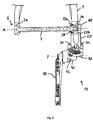
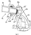
- FIG. 1 shows a perspective view of the rear axle mounted coaxially on the rear axle 6, according to the invention rear derailleur 10. For clarity, the rear wheel and the sprocket set are not shown.
- the rear hub 3 arranged between the two dropouts of the frame 1 and the rear dropout embracing the right dropout 10 are shown.
- the base element 20 is mounted on the frame 1 coaxially with the axis A by means of the adapter 60.
- FIG. 2 shows a section along the axis A of in FIG. 1 illustrated rear derailleur 10 in the rear view.
- the geometric axis A extends along the Schuradachse 6.
- the base member 20 is fixed by means of the adapter 60 at the right dropout.
- the adapter 60 passes through the right frame opening 2b.
- the thru axle 7 is inserted into the left frame opening 2a and bolted to the adapter 60.
- the adapter 60 also serves as a counter to the thru axle 7. When the thru axle 7 is tightened, it continues to screw into the adapter 60 and clamps against the frame first
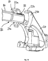
- FIG. 3 shows a side view of the invention mounted on the frame 1 rear derailleur 10 from FIG. 2
- the FIGS. 1 to 3 each show the entire rear derailleur 10 with the base member 20, the pivot mechanism 30, the movable member 40 and the chain guide assembly 50.
- On the base member 20 is a cable guide 11, arranged here in the form of a rotatably mounted at the junction 29c Seilumlenkungsrolle.
- the base member 20 is mounted at its first, upper terminal end coaxial with the rear wheel axle A on the frame 1.
- two axially spaced apart arms of the base member 20 embrace the dropout of the frame 1, so that an arm on the inside of the frame 1 and the other arm on the outside of the frame 1 is arranged.
- the base member 20 is preassembled with the adapter 60 on the frame 1. Further, the base member 20 is coupled to the pivot mechanism 30 at its second lower terminal end.
- the pivot mechanism 30 is formed as a parallelogram four-bar link with an inner pivot arm 35, an outer pivot arm 36 and four pivot axes 31, 32, 33, 34.
- the four pivot axes 31, 32, 33, 34 each extend in planes that intersect the axis A at right angles. In other words, the pivot axes 31, 32, 33, 34 lie in planes that extend parallel to the not shown rift planes (see. FIGS. 11 to 13 ).
- the first and second pivot axes 31, 32 connect the pivot mechanism 30 to the base member 20.
- the third and fourth pivot axes 33, 34 connect the pivot mechanism 30 to the movable member 40.
- Both the base member 20 and the movable member 40 each have two seats for the swivel axes.
- the longitudinal axes L1, L2 of the receptacles on the base element 20 and the longitudinal axes of the receptacles on the movable element 40 are like the pivot axes 31, 32, 33, 34th even orthogonal to the rear wheel axle 6 and the axis A aligned (see. FIGS. 4 to 9 ).
- the chain guide assembly 50 is rotatably connected to the movable member 40 about the axis P and biased in the UZS (backward), so that a not shown here, the chain guide 50 S-shaped continuous chain is tensioned.
- the chain guide assembly 50 includes an upper and a lower Ketten Entrysröllchen 51, 52, which are each rotatably mounted between two cage halves 57 a, 57 b.
- the upper Ketten Entrysröllchen 51 is rotatably disposed at an upper distance from the axis P about the upper axis of rotation 55.
- the lower Ketten Entrysröllchen 56 is rotatably disposed at a lower distance from the P axis about the lower Drehasche 56, wherein the upper Ketten Entrysröllchen 51 is arranged at a smaller distance from the P axis than the lower Ketten Entrysröllchen 52.
- the movable element 40 has a locking element 42 which allows the pretensioned chain guide arrangement 50 to be fixed relative to the movable element 40.
- the rear derailleur 20 can be mounted without the chain guide assembly 50 snaps backwards due to the bias.
- the chain guide assembly 50 When switching to a smaller pinion, the chain guide assembly 50 rotates about the axis of rotation P of the movable member 40 in the UZS backwards. Conversely, the chain guide assembly 50 rotates forward when switching to a next larger pinion about the rotation axis P against the UZS.
- the upper Ketten Entrysröllchen 51 radially on the pinion or moved away.
- the chain guide assembly 50 In the axial direction, the chain guide assembly 50 is moved by the pivot arms 35, 36 are pivoted about the pivot axes 31, 32, 33, 34.
- the upper Ketten Entrysröllchen 51 moves together with the entire chain guide assembly 50 in the axial direction inwards or outwards.
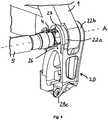
- FIG. 4 and 5 show in each case perspective partial sections of the mounted with the aid of the adapter 60 to the frame 1 base member 20 and parts of the hub assembly.
- the first arm 22 a and the second arm 22 b are respectively positioned on one side of the frame 1.
- the hub assembly here only the hollow shaft 5 is shown
- the hub guide 27 is formed as a collar with converging guide surfaces.
- the hub end cap 4 abuts radially on the hub guide 27 in its end position. In the axial direction, the hub end cap 4 abuts against the axial hub stop surface 26 on the inside of the base member 20.
- the hub end cap 4 is shown cut.
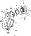
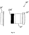
- FIG. 5 shows a section through the base member 20 with the two adapters 60 embracing arms 22a, 22b.
- the adapter 60 consists of the bolt 61 and the nut 66.
- the bolt 61 is screwed into the nut 66, so that the bolt head 62 and the nut 66 are clamped to the frame 1.
- the adapter 60 is so fixed relative to the frame 1.
- the base member 20 is centered on the adapter 60. In running order, with stuck-through axle 7, the base member 20 is clamped between the hub end cap 4 and the adapter 60 rotatably.
- the base member 20 is in the assembled state in the axial direction only on the hub end cap 4 and the adapter 60 at.
- the base member 20 is indirectly mounted to the frame 1 via the adapter 60.
- the base member 20 and thus the entire rear derailleur 10 is referenced to the hub 4 - and not as usual on the frame first
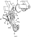
- FIG. 6 shows the enlarged partial section of the adapter 60 mounted on the frame 1 base member 20 from FIG. 5 ,
- the bolt head 62 and the nut 66 are sized larger than the frame opening 2b.
- the nut 66 has a knurled surface 69, in addition to produce a positive connection to the frame 1 and counteract a twisting of the rear derailleur 10 forward (against the UZS).
- the bolt body 63 has an abutment portion 63a which abuts against the frame hole 2b with little play and a balance portion 63b which has more clearance than the frame hole 2b.
- the compensation region 63b allows the adapter 60 to align in the frame opening 2b along the axis A.
- the bolt 61 has play in the frame opening 2b and can tilt it slightly if the frame opening is not exactly aligned with the axis A.
- FIG. 7 shows the arrangement FIG. 6 with cut adapter 60.
- the adapter 60 has two purposes: 1) The clamping on the frame 1 is determined by the Screwed between bolt 61 and nut 66 made. Alternatively, the nut could be arranged outside and the bolt inside. It is important that the adapter 60 relative to the frame 1 can be fixed and is adaptable to this in the axial direction. With a thinner frame, the screw connection is tightened further than with a thicker frame. 2) The adapter 60 is only limitedly rotated relative to the base member 20 in UZS and thus provides an anti-rotation. For this purpose, two stops 68a, 68b are arranged on the nut 66, which cooperate with two pins 24a, 24b on the base member 20.
- a rotation of the rear derailleur 10 forward (against UZS) is due to the rotation between adapter 60 and base member 20 only limited possible.
- the external thread 64 and the internal thread 65 of the bolt 61 are arranged in different areas along the bolt 61 so as to better absorb forces.
- the plug-in shaft 7 is screwed into the internal thread 65 and pulls the adapter 60, in particular the bolt head 62, against the outside of the frame 1.
- a washer between the bolt head 62 and the frame 1 is arranged.
- FIG. 8 An exploded view of the unassembled base member 20 and the adapter 60 from FIG. 7 , In this view, the internal thread 67 of the nut 66 and the external thread 64 of the bolt 61, which together form the screw connection of the adapter 60, are clearly visible. Alternatively, the bolt could also be screwed directly into a thread of the frame opening. But then frame tolerances would directly affect the rear derailleur, which should be avoided. Furthermore, the bolt foot 63c, which is matched to the first centering opening 23a, and the bolt head 62, which is matched to the second centering opening 23b, can be seen. The abutment surface 63d of the bolt 61 cooperates with the side of the first arm 22a of the base element 20 facing away from here (cf. FIG. 9a ).
- FIGS. 9a and 9b show an outside and inside perspective view of the base member 20 with the first and second centering openings 23a, 23b.
- the first Centering opening 23a is matched to the outer diameter of the bolt foot 63c of the bolt 61.
- the second centering opening 23b is matched to the outer diameter of the bolt head 61.
- the adapter stop surface 25 can be seen, which cooperates with the abutment surface 63d of the bolt 61.
- the hub abutment surface 26 is arranged.
- connection point 29c for a cable guide 11.
- first receptacle 29a for the first pivot axis 31
- second receptacle 29b for the second pivot axis 32 of the pivot mechanism not shown here 30.
- the longitudinal axes L1, L2 of the first and second receptacles 29a, 29b extend in planes which intersect the rear wheel axis A at right angles.
- the four pivot axes 31, 32, 33, 34 of the parallelogram four-bar linkage 30 are therefore aligned orthogonal to the common pinion axis A, regardless of the selected relative position of the derailleur 10.
- FIG. 10 shows a partial section through the second embodiment of the rear derailleur 10 according to the invention with an adjustment.
- the cut passes through the movable member 40 and the chain guide assembly 50.
- the adjustment aid is in the form of the locking member 42 which engages the locking aperture 58 in the outer cage half 57b.
- the UZS pre-tensioned chain guide assembly 50 is fixed relative to the movable member 40 in a predetermined rotational position.
- the predetermined rotational or angular position defines the upper Ketten Entrysröllchen 51 at an ideal distance from a reference pinion of the sprocket set, not shown here.
- To set the rear derailleur 10 this is locked by means of the adjustment. After adjustment, the lock is released so that the chain guide assembly 50 can rotate relative to the movable member 40.
- FIG. 11 and 12 show third embodiments of the rear derailleur 10 according to the invention with limit stops 59a and 59b, which make it possible to dispense with the usual limiting screws 70 (limit screws).
- limit screws 70 are in FIG. 12 still shown.
- the rear derailleur 10 in FIG. 11 is aligned with the largest pinion R12 of the sprocket set R. This position represents the inner maximum position.
- the rear derailleur 10 should not move further in the axial direction.
- the first limit stop 59a is arranged on the chain guide arrangement 50, in particular on the inside of the outer cage half 57b.
- the first limit stop 59a is formed to cooperate with the largest pinion R12.
- the inner limit stop 59a protrudes beyond the cage 57b in the region of the P axis and abuts in the inner maximum position against the outside of the cage Ritzel's R12.
- the chain guide assembly 50 can then not be moved further inward with respect to the largest pinion R12 in the axial direction.
- the outer cage half 57b of the chain guide assembly 50 radially extends in the inner maximum position of the derailleur 10 into a region of the largest pinion R12 which is within the radial outer diameter of the largest pinion R12. In the axial direction, the outer cage half 57b extends in the inner maximum position of the derailleur 10 between the largest pinion R12 and its adjacent next smaller pinion R11. In the inner maximum position of the derailleur 10, a chain, not shown here is in engagement with the largest pinion R12. If the rear derailleur 10 continues to move inwards in the axial direction beyond the inner maximum position, the outer cage half 57b or the inner limit stop 59a abuts against the largest pinion R12 and thus limits the movement of the rear derailleur 10.
- the inner limit stop 59a is here in one piece the outer cage half 57b formed. Multi-part versions of cage and limit stop are also conceivable.
- the movable element may be formed such that it acts as an inner limit stop in the intended, inner maximum position of the derailleur.
- the inner limit stop cooperates with the sprocket set, in particular a sprocket or another suitable element associated with the sprocket set, for example a chain guard.
- the derailleur 10 is aligned with the smallest pinion R1 of the sprocket set R.
- the chain guide assembly 50 is rotated much farther back (in the UZS).
- the upper Ketten Entrysröllchen 51 is approximately equidistant from the pinion R1 in the radial direction, as in FIG. 12 from the pinion R12.
- the position shown represents the outer maximum position of the rear derailleur 10.
- the rear derailleur 10 should not move further outward in the axial direction.
- the second limit stop 59b is arranged on the chain guide arrangement 50, in particular the outside of the outer cage half 57b.
- the second limit stop 59 a is designed to be connected to the base element 20 interacts.
- the outer side of the outer cage half 57b in the region of the upper chain guide roller 51 acts as a second limit stop 59b.
- the second limit stop 59b abuts in the outer maximum position against the inside of the base member 20.
- the inside of the base member 20 is also the inside of the first arm 22a. The chain guide assembly 50 can then not be moved further outwardly relative to the base member 20 in the axial direction.
- limit stops 59a, 59b An advantage of the limit stops 59a, 59b is that these fixed stops no longer need to be adjusted, but are already tuned to the sprocket package R.
- the limit screws 70 for adjusting the stops are no longer necessary.
- FIG. 14 shows a sectional view of a fourth embodiment along the axis A in the rear view.
- the frame 1, the thru-axle 70, the right hub end cap 4 and selected parts of the derailleur are shown in this illustration. All parts to be seen are shown cut.
- the base member 20 is fixed by means of the adapter 60 at the right dropout.
- the bolt 61 passes through the right frame opening 2b and is screwed to the nut 66.
- the plug-in shaft 70 is inserted with its first end 71 in the left frame opening 2a and screwed with its second end 72 in the pin 61 of the adapter 60.
- the adapter 60 or the bolt 61 serves as a counter to the plug-in axis 70.
- the outer diameter 74 of the plug-in shaft 70 is dimensioned smaller than the frame opening 2a. The gap is balanced with a bushing 71a.
- the first thru-axle end 71 has a head with a larger diameter than the frame opening 2a, and can not slip through the frame opening 2a.
- Head diameter decreases continuously from the first end 71 to the body or shaft of the through axle 70 down to the outer diameter 74.
- the transition is at a 45 degree angle.
- Other angular dimensions, in particular 90 degrees, are also conceivable.
- the inner arm 22 a of the base member 20 is fixed in the axial direction between the right hub end cap 4 and the bolt 61.
- the inner arm 22a of the base member 20 is moved radially on the centering portion of the bolt 61 (refer to details in FIG FIG. 7 and 8th ) and the outer arm 22b is centered on the bolt head 62.
- the plug-in shaft 70 shown has an outer diameter 74 of 12 mm and an inner diameter 75 of 7 mm. This results in a thru-axle thickness of 2.5 mm.
- the embodiment of the plug-in axis 70 in FIG. 14 corresponds essentially to the previous figures, but here again directly to a thru axle 80 according to FIG. 15a faced with an enlarged outer diameter 84 and a differing centering.
- FIG. 15a shows a sectional view of a fifth embodiment, which differs due to the thru-axle 80 with an enlarged outer diameter 84 in several points from the previous embodiment.
- the thru-axle 80 shown has an outer diameter 84 of 15 mm and a first inner diameter 85 of 12 mm. This leads to a first wall thickness W85 of 1.5 mm. All parts shown are cut.
- the frame 1 with its frame openings 2a and 2b, the hub assembly only partially shown here with the hub end cap 4 and the base member 20 of the derailleur are unchanged. Only the adapter 60 'must be adapted to the enlarged outer diameter 84 of the thru axle 80. In order to accommodate the thru-axle 80, the diameter of the internal thread 65 'of the bolt 61' is adapted to its outer diameter 84. In addition, the centering area (see centering area 63 c of the preceding embodiments) on the bolt 61 'falls away. As a result, the base member 20 directly contacts the outer peripheral surface of the thru-axle 80.
- the inner arm 22a of the base member 20 is centered directly on the through axle 80, and not on the adapter 60 as in the previous examples.
- the outer arm 22b of the base member is centered unaltered on the outer circumference of the bolt head 62 '.
- the referencing the base element 20 in the axial direction and in the radial direction is independent of the frame 1.
- the base member 20 between hub end cap 4 and the adapter 60 ' in particular the abutment surface 63d' of the bolt 61 '(see FIG. 19 ).
- the inner arm 22a of the base member 20 is centered directly on the through axle 80 and the outer arm 22b on the adapter 60 ', in particular on the bolt head 62'.
- the wide independence of frame tolerances allows a precise alignment of the derailleur even if the two frame openings 2a and 2b are not exactly aligned.
- the transition between the head at the first end 81 of the thru axle 80 to the thru axle body with the outer diameter 84 is rectangular here.
- the outer diameter 84 of the plug-in axis 80 corresponds approximately to the frame opening 2a.
- the thru-axle 80 is guided through the opening 2a with less play.
- the sleeve 91a has a 45 degree angle and serves to center the through-axle 80 in the frame opening 2a. This socket could also be formed at a different angle.
- FIG. 15b an external perspective view of the sectional view FIG. 15a ,
- the hub end cap 4 abuts axially against the hub abutment surface 26 of the base member 20.
- FIG. 16 is an enlarged detail view of the right dropout of the frame 1 from FIG. 15b shown.
- the second end 82 of the plug-in axis 80 is screwed into the internal thread 65 'of the bolt 61' of the adapter 60 '.
- the inner arm 22a of the base element 20 lies with its first centering opening 23a in the radial direction directly on the outer circumference of the plug-in axis 80. In the axial direction, the inner arm 22a is fixed between the hub end cap 4 and the abutment surface 63d 'of the bolt 61'.
- the nut 66 ' substantially corresponds to the previous embodiments.
- FIG. 17 corresponds to the view FIG. 16 , wherein for better clarity, the hub end cap and the adapter nut have been hidden.
- FIG. 18 shows the arrangement FIG. 17 without the bolt.
- the centering of the base member 20 on the thru-axle 80 is particularly clear.
- the second end 82 of the plug-in axis 20 passes through the inner arm 22a of the base member 20.
- the external thread 83 of the plug-in axis 80 is in the assembled state between the first and the second arm 22a, 22b of the base member 20.
- the surface 87 of the thru-axle 80 is machined at least in the contact region between the base member 20 and thru-axle 80.
- This centering surface 87 is, for example, finely turned, ground and / or coated. Due to the complex processing, the centering surface 87 is kept as narrow as possible. However, the centering surface 87 must be at least as wide as the first centering hole 23 a of the first arm 22 a of the base member 20.
- the centering surface 87 of the plug-in shaft 80 in the assembled state reaches at least into the area of the bolt 61 ', so that the bolt foot comes to rest on the centering surface 87.
- This embodiment allows a precise centering of the bolt 61 'on the thru-axle 80.
- the centering by screwing the external thread 83 of the thru-axle 80 into the internal thread 65' of the bolt 61 'alone is not precise enough due to the thread play.
- the centering surface 87 takes the game between the bolt 61 'and thru axle 80 out.
- a particularly rigid connection between the thru axle 80 and the pin 61 ' is possible.
- the centering surface 87 should have a minimum width so that tolerances depending on the depth of engagement, depending on the hub assembly and frame width, can be compensated and the base member 20 always comes to rest on the surface 87.
- An axial width of the centering surface 87 of about 2.5 mm (or more) is sufficiently wide and can be made relatively quickly and inexpensively.
- Another centering surface could be attached to the outermost second end of the thru axle, which also cooperates with the bolt and to a even stiffer connection leads.
- the outer surface of particularly high-quality thru axles could also be completely reworked.
- FIG. 19 shows an enlarged exploded view in the uncut rear view of the adapter 60 ', consisting of the bolt 61' and the nut 66 '.
- the adapter 60 ' substantially corresponds to the adapter 60 of the previous embodiment in the FIGS. 1 to 12 why only the differences are discussed here.
- the enlarged in diameter and adapted to the 15 mm thru-axle 80 internal thread is not visible in the rear view.
- the stopper 63d ' forms the inner axial end of the bolt 61'.
- the remaining outer dimensions of the bolt 61 ' are unchanged and matched to the base member 20.
- a thru-axle 80 according to the fifth embodiment is shown in an uncut rear view in FIG FIG. 20a and in a sectional view taken along the axis A in FIG FIG. 20b shown.
- the thru-axle 80 has an outer diameter 84 of 15 mm.
- the overall axial width from the first end 81 to the second end 82 varies depending on the hub standard used and the constraints. Typical hub widths from left to right hub end caps are 142 to 148 mm.
- the external thread 83 and the centering surface 87 are arranged in the region of the second axle end 82. The centering surface 87 is located axially further inwardly than the external thread 83.
- the centering surface 87 begins at a distance 88 of about 13.5 mm and ends at a distance 88 of about 16 mm from the second plug axis end 82.
- the centering surface 87 has an axial width B87 of about 2.5 mm.
- the axial width B83 of the external thread 83 measures about 10 mm.
- the thru-axle 80 has an outer diameter 84 of 15 mm. Only the first end 81 has a larger head diameter.
- a first inner diameter 85 of the plug-in axis 80 is 12 mm. This results in a first wall thickness W85 of about 1.5 mm.
- the first wall thickness W85 extends over a large part of the axial width of the plug-in axis 80.
- the second inner diameter 86 is smaller than the first inner diameter 85. From the second inner diameter 86 results in a second wall thickness W86, the larger as the first wall thickness is W85.
- the second wall thickness W86 is sized at about 2.4 mm.
- the second inner diameter 86 and the enlarged second wall thickness W86 is located just in the areas of the plug-in axis 80, which are heavily loaded. In particular, in the region of the external thread 83.
- the area of the centering surface 87 has an increased wall thickness W86, because here the base member 20 rests on the plug-in axis 80 and correspondingly larger forces act.
- the transition between the first and second inner diameter W85, W86 is continuous.
- the second inner diameter 86 extends from the outermost second axle end 82 in the axial direction over a width B86 of about 18 mm.
- first end 81 with enlarged head diameter From the first end 81 to the second end 82 of the plug-in axis 80, the following areas are lined up: first end 81 with enlarged head diameter, right-angled transition to the outer diameter 84, first inner diameter 85 with the resulting wall thickness W85, transition from the first inner diameter 85 to the second inner diameter 86 with the resulting wall thickness W86, centering surface 87, external thread 86 and second plug axis end 82nd
- FIG. 21 shows a sectional view of a Häradachsan Aunt with a thru axle 80 according to the fifth embodiment. All parts are shown cut.
- the thru axle 80 engages in the assembled state, the frame opening 2a, the hub assembly and the driver 100 and is in the rear derailleur, in particular the adapter 60 'is screwed.
- the derailleur (shown only partially here) is attached via the base member 20 and the adapter 60 'to the right dropout of the frame 1.
- the hub assembly With the thru axle 80, the hub assembly is attached to the frame 1.
- the base member 20 is braced against the hub assembly, in particular the right hub end cap 4 in the axial direction.
- the rear derailleur including adapter 60 'and base member 20 remains on the frame 1.
- the hub assembly includes, among other things, the left hub end cap 8, the hub bearing 9, the hub shell 3, the hub axle 5 and the right hub end cap 4.
- FIG. 22 shows selected parts of the Hinterradachsan Aunt FIG. 21 , For clarity, the driver and most parts of the hub assembly have been removed here. Only the hub axle 5 and the hub bearing 9, consisting of the hub bearings 9a, 9b of the hub assembly designed as roller bearings, are shown. The thru axle 80 is inserted with little play in the hub axle 5. The hub bearings 9a, 9b and the driver bearings 109a, 109b are fitted on the hub axle 5. All parts are shown cut.
- FIG. 23 shows the sectional view of Hinterradachsan Aunt FIG. 22 without the bearings.
- the thru-axle 80 with an outer diameter 84 of 15 mm is inserted into the hub axle 5 with little play.
- the inner diameter d5 of the hub axle 5 is slightly more than 15 mm.
- the outer diameter D5 of the hub axle 5 is about 17 mm.
- the wall thickness W85 of the plug-in axle 80 is greater than the wall thickness W5 of the hub axle 5.
- the wall thickness W85 of the plug-in axle 80 is approximately 1.5 mm and thus 1.5 times the hub axle 5. This leads to a relatively balanced ratio of the area moments of inertia ,
- FIG. 24a shows a partial section through selected parts of a Häradachsan Aunt with a thru axle 90 according to the sixth embodiment. Except the thru axle 90, all parts are shown cut.
- FIG. 24b shows the partial section FIG. 24a in a perspective exterior view.
- the through axle 90 passes through the left frame opening 2a, the hub end caps 8, 4 and the hub axle 5 with little play.
- the second axle end 92 is screwed with the external thread 93 in the adapter 60 'of the rear derailleur.
- the first outer diameter 94a of the plug-in axle 90 is slightly smaller than the inner diameter of the hub axle 5.
- the plug-in axle 90 has the first outer diameter 94a in the areas of increased load. These are in particular the plug-axis ends 91, 92 and the areas of the bearings 9a, 9b, 109a, 109b.
- the remaining areas of the plug-in axis 90 have a second, reduced outer diameter 94b.
- the thru-axle 90 according to the sixth embodiment is in an uncut rear view in FIG. 25a and in a sectional view taken along the axis A in FIG FIG. 25b shown.
- the thru-axle 90 differs from the thru-axle 80 primarily in that it has a reduced wall thickness W94b in large areas in order to save weight.
- the thru-axle 90 has a first outer diameter 94a of 15 mm and a first inner diameter 95 of 12 mm.
- the first outer diameter 94a of 15 mm was reduced to a second outer diameter 94b of 14 mm.
- the first inner diameter 95 remains unchanged. This results in the region of the first outer diameter 94a, a first wall thickness W94a of 1.5 mm and in the region of the reduced outer diameter 94b, a second, reduced wall thickness W94b of 1 mm.
- the thru-axle 90 only has the larger outer diameter 94a and the greater wall thickness W94b in the axial areas which are subject to a greater load.
- the plug-in axis 90 in the region of the second end 92 has a second smaller inner diameter 96, which is about 10 mm. From the second inner diameter 96 results in a third wall thickness W96, which is greater than the first and the second wall thickness W94a, W94b.
- the second inner diameter 96 or the enlarged second wall thickness W96 is arranged in the heavily loaded region of the external thread 93 and the centering surface 97.
- first end 91 with increased head diameter, right-angled transition to the first outer diameter 94a, first inner diameter 95 with the resulting wall thickness W94a in the more heavily loaded areas, between the reduced outer diameter 94b with the resulting reduced wall thickness W94b, transition from the reduced outer diameter 94b to the second inner diameter 96 with the resulting wall thickness W96, centering surface 97, external thread 96 and second axle end 92nd
- the reduced outer diameter 94b can be made particularly easily by twisting off the excess material on the outer side of the thru-axle 90.
- a reduced wall thickness could also be realized by a third, enlarged inner diameter. This material is removed or saved on the inside of the thru axle and not on the outside. The effect of weight saving would be the same.
- the thru axles 80, 90 with an enlarged outer diameter of 15 mm despite a smaller wall thickness of 1 mm to 2 mm have a much higher area moment of inertia compared to the thru axles 70 with a 12 mm outer diameter.
- the stiffness is increased and / or the weight is reduced.
- Another embodiment not shown here, as it could be used especially for e-bikes, is a thru-axle with an outer diameter of 15 mm and an inner diameter of 11 mm.
- the area moment of inertia is somewhat reduced but significantly reduced in weight.
- the more even distribution of the area moment of inertia on the through axle and hub axle leads to an overall more stable axle arrangement, because the maximum stresses on the outer skin of the hub axle are lower.
- both the stiffness and the weight can be further influenced.
- Preferred materials for the thru axle are aluminum, titanium or steel.
- the modular system allows a simple and cost-effective replacement of the axle 70, 80, 90th Depending on the type of bike and load either a stiffer or lighter thru axle can be selected. Only the adapter 60, 60 'must be adapted to the selected thru axle 70, 80, 90.
- the hub assembly, the driver 100, the base member 20 and the remaining parts of the rear derailleur can be used unchanged and are not affected by the change of the thru axle.
- the wall thicknesses of the hub and thru axles mentioned in the embodiments described above are designed for production from aluminum.
- the statements made regarding the moment of inertia are independent of material. As long as the same material is used for the thru axle and the hub axle, the aforementioned wall thickness ratios can be maintained.
- the wall thicknesses can be adjusted according to the maximum stresses.
- a thru axle made of titanium and a hub axle made of aluminum could be made. Then the thru-axle could be formed thin-walled according to the permissible yield strengths.
Landscapes
- Engineering & Computer Science (AREA)
- Mechanical Engineering (AREA)
- Chemical & Material Sciences (AREA)
- Combustion & Propulsion (AREA)
- Transportation (AREA)
- Axle Suspensions And Sidecars For Cycles (AREA)
- Devices For Conveying Motion By Means Of Endless Flexible Members (AREA)
- Transmissions By Endless Flexible Members (AREA)
- Automatic Cycles, And Cycles In General (AREA)
- Input Circuits Of Receivers And Coupling Of Receivers And Audio Equipment (AREA)
- Support Of Aerials (AREA)
- Steering Devices For Bicycles And Motorcycles (AREA)
- General Details Of Gearings (AREA)
- Steering-Linkage Mechanisms And Four-Wheel Steering (AREA)
Priority Applications (2)
| Application Number | Priority Date | Filing Date | Title |
|---|---|---|---|
| EP25225536.9A EP4707149A2 (fr) | 2017-03-20 | 2018-03-14 | Dérailleur arrière pour montage coaxial |
| EP23020162.6A EP4219281B1 (fr) | 2017-03-20 | 2018-03-14 | Dérailleur arrière pour montage coaxial |
Applications Claiming Priority (2)
| Application Number | Priority Date | Filing Date | Title |
|---|---|---|---|
| DE102017002629 | 2017-03-20 | ||
| DE102018001253.1A DE102018001253A1 (de) | 2017-03-20 | 2018-02-16 | Hinteres Schaltwerk zur koaxialen Montage |
Related Child Applications (3)
| Application Number | Title | Priority Date | Filing Date |
|---|---|---|---|
| EP23020162.6A Division-Into EP4219281B1 (fr) | 2017-03-20 | 2018-03-14 | Dérailleur arrière pour montage coaxial |
| EP23020162.6A Division EP4219281B1 (fr) | 2017-03-20 | 2018-03-14 | Dérailleur arrière pour montage coaxial |
| EP25225536.9A Division EP4707149A2 (fr) | 2017-03-20 | 2018-03-14 | Dérailleur arrière pour montage coaxial |
Publications (3)
| Publication Number | Publication Date |
|---|---|
| EP3388324A2 true EP3388324A2 (fr) | 2018-10-17 |
| EP3388324A3 EP3388324A3 (fr) | 2018-12-26 |
| EP3388324B1 EP3388324B1 (fr) | 2023-05-24 |
Family
ID=63372508
Family Applications (3)
| Application Number | Title | Priority Date | Filing Date |
|---|---|---|---|
| EP18000255.2A Active EP3388324B1 (fr) | 2017-03-20 | 2018-03-14 | Derailleur arrière destiné au montage coaxial |
| EP25225536.9A Pending EP4707149A2 (fr) | 2017-03-20 | 2018-03-14 | Dérailleur arrière pour montage coaxial |
| EP23020162.6A Active EP4219281B1 (fr) | 2017-03-20 | 2018-03-14 | Dérailleur arrière pour montage coaxial |
Family Applications After (2)
| Application Number | Title | Priority Date | Filing Date |
|---|---|---|---|
| EP25225536.9A Pending EP4707149A2 (fr) | 2017-03-20 | 2018-03-14 | Dérailleur arrière pour montage coaxial |
| EP23020162.6A Active EP4219281B1 (fr) | 2017-03-20 | 2018-03-14 | Dérailleur arrière pour montage coaxial |
Country Status (7)
| Country | Link |
|---|---|
| US (5) | US10870464B2 (fr) |
| EP (3) | EP3388324B1 (fr) |
| CN (2) | CN108622302B (fr) |
| DE (1) | DE102018001253A1 (fr) |
| ES (1) | ES2953658T3 (fr) |
| PL (1) | PL3388324T3 (fr) |
| TW (3) | TWI909661B (fr) |
Cited By (16)
| Publication number | Priority date | Publication date | Assignee | Title |
|---|---|---|---|---|
| EP3712052A1 (fr) | 2019-03-22 | 2020-09-23 | SRAM Deutschland GmbH | Raccordement coaxial de monte-et-baisse |
| EP3730394A3 (fr) * | 2019-04-25 | 2020-12-02 | SRAM Deutschland GmbH | Derailleur électromécanique destiné au montage coaxial |
| EP3782891A1 (fr) | 2019-08-23 | 2021-02-24 | SRAM Deutschland GmbH | Dérailleur de bicyclette pourvu d'affichage de réglage |
| EP3838731A2 (fr) | 2019-12-18 | 2021-06-23 | SRAM Deutschland GmbH | Dérailleur de bicyclette et raccordement d'un dérailleur à un cadre de bicyclette |
| US11230350B2 (en) | 2018-04-20 | 2022-01-25 | Sram Deutschland Gmbh | Derailleur hanger |
| EP4008622A1 (fr) | 2020-12-03 | 2022-06-08 | SRAM Deutschland GmbH | Mécanisme de commutation arrière destiné à la liaison coaxiale à un cadre de bicyclette |
| DE102021131414A1 (de) | 2020-12-03 | 2022-06-09 | Sram Deutschland Gmbh | Hinteres Schaltwerk zur koaxialen Anbindung an einem Fahrrad-Rahmen |
| EP4063252A1 (fr) | 2021-03-26 | 2022-09-28 | SRAM Deutschland GmbH | Rouleau de guide-chaîne pour dérailleurs de bicyclette, ainsi que dérailleur de bicyclette et chaîne cinématique de bicyclette |
| DE102022103284A1 (de) | 2021-03-26 | 2022-09-29 | Sram Deutschland Gmbh | Kettenführungsrolle für Fahrrad-Schaltwerk sowie Fahrrad-Schaltwerk und Fahrrad-Antriebsstrang |
| DE102022115599A1 (de) | 2021-06-29 | 2022-12-29 | Sram Deutschland Gmbh | Modulares Fahrrad-Schaltwerk |
| EP4112435A2 (fr) | 2021-06-29 | 2023-01-04 | SRAM Deutschland GmbH | Dérailleur modulaire de bicyclette |
| US11572134B2 (en) | 2019-08-23 | 2023-02-07 | Sram Deutschland Gmbh | cycle derailleur with setting indicator |
| US11713096B2 (en) | 2019-03-22 | 2023-08-01 | Sram Deutschland Gmbh | Coaxial gearshift mechanism connection |
| US20230406448A1 (en) * | 2020-09-03 | 2023-12-21 | Sram Deutschland Gmbh | Electromechanical derailleur for coaxial assembly |
| US11866127B2 (en) | 2019-04-25 | 2024-01-09 | Sram Deutschland Gmbh | Electromechanical rear derailleur for coaxial mounting |
| US11939029B2 (en) | 2019-12-18 | 2024-03-26 | Sram Deutschland Gmbh | Bicycle rear derailleur and frame connection |
Families Citing this family (33)
| Publication number | Priority date | Publication date | Assignee | Title |
|---|---|---|---|---|
| DE102018001253A1 (de) * | 2017-03-20 | 2018-09-20 | Sram Deutschland Gmbh | Hinteres Schaltwerk zur koaxialen Montage |
| US10464634B2 (en) * | 2017-07-12 | 2019-11-05 | Shimano Inc. | Bicycle rear derailleur |
| US10766301B2 (en) * | 2017-12-14 | 2020-09-08 | Shimano Inc. | Rear wheel fixing mechanism for a bicycle |
| US10981626B2 (en) * | 2018-03-20 | 2021-04-20 | Sram Deutschland Gmbh | Drive arrangement for a bicycle |
| TWM562816U (zh) * | 2018-04-03 | 2018-07-01 | 彥豪金屬工業股份有限公司 | 變速器總成 |
| DE102018214218A1 (de) * | 2018-08-22 | 2020-02-27 | Sram Deutschland Gmbh | Hinterrad-Kettenschaltwerk mit exzentrischer Seilzug-Umlenkrollenanordung mit Übersetzungsverhältnis |
| US11428279B2 (en) * | 2018-11-26 | 2022-08-30 | Fox Factory, Inc. | Suspension enhancing hub and rear derailleur assembly |
| DE102018222834A1 (de) * | 2018-12-21 | 2020-06-25 | Sram Deutschland Gmbh | Halterungselement und Fahrrad mit einem Halterungselement |
| CN109703688A (zh) * | 2019-01-08 | 2019-05-03 | 珠海迪瑞乐科技有限公司 | 自行车拨链机构及自行车拨链器 |
| TWI730290B (zh) * | 2019-02-13 | 2021-06-11 | 彥豪金屬工業股份有限公司 | 自行車後變速器的固定組件 |
| US11498643B2 (en) * | 2019-02-26 | 2022-11-15 | Shimano Inc. | Bicycle electric derailleur |
| US11608139B2 (en) * | 2019-05-13 | 2023-03-21 | Shimano Inc. | Bicycle rear derailleur |
| US11511826B2 (en) * | 2019-12-09 | 2022-11-29 | Sram, Llc | Bicycle axle assembly including a power meter |
| EP3904193B1 (fr) * | 2020-04-30 | 2024-08-28 | Fantic Motor S.p.A. | Dispositif de positionnement sélectif de pivot d'une roue |
| TWI742700B (zh) * | 2020-05-29 | 2021-10-11 | 彥豪金屬工業股份有限公司 | 自行車後變速器 |
| TWI867135B (zh) * | 2020-12-31 | 2024-12-21 | 日商島野股份有限公司 | 托架裝置 |
| TWI895327B (zh) * | 2020-12-31 | 2025-09-01 | 日商島野股份有限公司 | 後撥鏈器 |
| TWI912320B (zh) | 2021-05-24 | 2026-01-21 | 新加坡商島野(新)私人有限公司 | 人力驅動車之後變速器 |
| CN115675719A (zh) * | 2021-07-26 | 2023-02-03 | 株式会社岛野 | 后拨链器 |
| JP2023028813A (ja) | 2021-08-20 | 2023-03-03 | 株式会社シマノ | 人力駆動車用のリアディレイラ |
| TWI800929B (zh) * | 2021-09-27 | 2023-05-01 | 彥豪金屬工業股份有限公司 | 自行車後變速器 |
| JP2023057889A (ja) | 2021-10-12 | 2023-04-24 | 株式会社シマノ | 人力駆動車用のリアディレイラ |
| JP2023057891A (ja) | 2021-10-12 | 2023-04-24 | 株式会社シマノ | 人力駆動車用のリアディレイラ |
| JP2023057890A (ja) | 2021-10-12 | 2023-04-24 | 株式会社シマノ | 人力駆動車用のリアディレイラ |
| US12358592B2 (en) * | 2021-12-09 | 2025-07-15 | Sram, Llc | Bicycle derailleur |
| US12145693B2 (en) * | 2022-09-16 | 2024-11-19 | Shimano Inc. | Bicycle derailleur |
| DE102023206797A1 (de) * | 2023-07-18 | 2025-01-23 | Shimano Inc. | Schaltwerk für ein menschlich angetriebenes fahrzeug und komponente für ein menschlich angetriebenes fahrzeug |
| DE102023119709A1 (de) | 2023-07-25 | 2025-01-30 | Sram Deutschland Gmbh | Fahrradschaltwerk und Verfahren zum Montieren eines Fahrradschaltwerks |
| US12059922B1 (en) | 2023-09-05 | 2024-08-13 | Red Star Holdings, Llc | Bicycle hub system, method and device including an interchangeable hub locking mechanism |
| US12059923B1 (en) | 2023-09-05 | 2024-08-13 | Red Star Holdings, Llc | Bicycle hub system, method and device including a rear hub locking mechanism |
| US12059924B1 (en) | 2023-09-05 | 2024-08-13 | Red Star Holdings, Llc | Bicycle hub system, method and device including a front hub locking mechanism |
| US11975802B1 (en) | 2023-09-05 | 2024-05-07 | Red Star Holdings, Llc | Bicycle hub system, method and device including an interchangeable rear hub with a direct mount derailleur |
| US12552493B2 (en) * | 2024-05-02 | 2026-02-17 | Shimano Inc. | Derailleur hanger |
Family Cites Families (99)
| Publication number | Priority date | Publication date | Assignee | Title |
|---|---|---|---|---|
| US2108941A (en) * | 1936-04-14 | 1938-02-22 | Morgan Joseph Thomas | Change speed gear mechanism for cycles and the like |
| GB645791A (en) * | 1948-10-18 | 1950-11-08 | Frederick James William Markle | A foot-controlled derailleur change speed gear for cycles |
| GB660230A (en) * | 1949-02-10 | 1951-10-31 | Hercules Cycle And Motor Compa | Improvements in or relating to variable gear mechanism for cycles |
| US3111855A (en) * | 1960-05-31 | 1963-11-26 | Juy Lucien Charles Hippolyte | Change speed gear mechanism for bicycles and the like vehicles |
| US3184993A (en) * | 1963-12-11 | 1965-05-25 | Carl A Swenson | Derailleur guard |
| DE2314554C2 (de) * | 1973-03-23 | 1983-10-06 | Fichtel & Sachs Ag, 8720 Schweinfurt | Kettenschaltung mit Änderung des Anstellwinkels des Leitrades |
| FR2225327B1 (fr) * | 1973-04-16 | 1976-09-10 | Juy Lucien | |
| US3903751A (en) * | 1974-04-24 | 1975-09-09 | Beatrice Foods Co | Bicycle derailler with overload cable protection means |
| US4027542A (en) * | 1974-10-04 | 1977-06-07 | Shimano Industrial Company, Limited | Derailleur for bicycle |
| US3964330A (en) * | 1974-11-08 | 1976-06-22 | Maeda Industries, Ltd. | Chain guide connector device for use in bicycle derailleurs |
| US3979962A (en) * | 1974-12-12 | 1976-09-14 | Alex Kebsch | Bicycle gear shift derailleur |
| FR2314093A1 (fr) * | 1975-06-12 | 1977-01-07 | Huret Roger | Derailleur pour bicyclette |
| DE2654426A1 (de) * | 1975-12-02 | 1977-06-23 | Simplex Ets | Gangschaltung fuer fahrraeder oder aehnliche fahrzeuge |
| US4215872A (en) * | 1979-02-07 | 1980-08-05 | Clark Marion A | Positive shift derailleur mechanism |
| US4371064A (en) * | 1979-08-28 | 1983-02-01 | Shimano Industrial Company Limited | Drive and brake device for a bicycle |
| JPS56135391U (fr) * | 1980-03-14 | 1981-10-14 | ||
| FR2496587B1 (fr) * | 1980-12-23 | 1986-02-28 | Bridgestone Cycle Co | Changement de vitesses pour bicyclette |
| DE3113439A1 (de) * | 1981-04-03 | 1982-10-21 | Fichtel & Sachs Ag, 8720 Schweinfurt | Nabe fuer fahrraeder o.dgl. mit schnellspann-einrichtung zur befestigung der nabenachse |
| FR2508862A1 (fr) * | 1981-07-03 | 1983-01-07 | Simplex Ets | Dispositif de commande assurant des positions multiples preetablies et controlees, applicable en particulier aux changements de vitesse pour les cycles et vehicules similaires |
| JPH0671916B2 (ja) * | 1984-12-29 | 1994-09-14 | 島野工業株式会社 | 自転車用デイレ−ラ− |
| JPS63119196U (fr) * | 1987-01-28 | 1988-08-02 | ||
| JPS63195992U (fr) * | 1987-06-06 | 1988-12-16 | ||
| ES2037277T3 (es) * | 1987-07-24 | 1993-06-16 | Marelmo Di Marchigiano G., Ezzu L., Mogno G.P. S.N.C. | Descarrilador trasero para cambios de marcha de bicicletas. |
| US4789379A (en) * | 1987-10-06 | 1988-12-06 | Maeda Industries, Ltd. | Bicycle deraileur |
| US4905541A (en) * | 1988-09-29 | 1990-03-06 | Huffy Corporation | Derailleur guard |
| US5134897A (en) * | 1989-10-20 | 1992-08-04 | Campagnolo S.R.L. | Twist-grip device for operating the gears of a bicycle |
| CN2061550U (zh) * | 1990-02-14 | 1990-09-05 | 裘百占 | 自行车同轴变速器 |
| JP3375163B2 (ja) * | 1993-02-03 | 2003-02-10 | 株式会社シマノ | 自転車用リヤディレーラ |
| US5494307A (en) * | 1993-09-09 | 1996-02-27 | Anderson; Paul M. | Gear shifting apparatus |
| JP2607328Y2 (ja) * | 1993-11-12 | 2001-07-09 | 株式会社シマノ | 自転車用リヤディレーラ |
| JP3372616B2 (ja) * | 1993-11-30 | 2003-02-04 | 株式会社シマノ | 自転車用ディレーラ |
| JPH07156855A (ja) * | 1993-12-06 | 1995-06-20 | Nobuo Ozaki | 自転車用リヤディレーラおよびその取付け構造 |
| US5624334A (en) * | 1995-11-03 | 1997-04-29 | Avid Enterprises, Inc. | Low-friction derailleur cable router |
| US5961409A (en) * | 1996-12-26 | 1999-10-05 | Shimano, Inc. | Rear derailleur for a bicycle |
| US5919106A (en) * | 1997-04-30 | 1999-07-06 | Shimano, Inc. | Quick release derailleur |
| TW341218U (en) * | 1997-05-14 | 1998-09-21 | Falcon Cycle Parts Co Ltd | A bicycle multi-stage flywheel automatic shift system |
| US6015360A (en) * | 1998-06-17 | 2000-01-18 | Falcon Industrial Co., Ltd. | Automatic gearshifting device of multi-stage fly wheel of bicycle |
| US6793598B1 (en) * | 1998-08-26 | 2004-09-21 | Shimano Inc. | Rear derailleur device for a bicycle |
| US6293883B1 (en) * | 1998-09-10 | 2001-09-25 | Shimano, Inc. | Quick release derailleur |
| US6676549B1 (en) * | 1998-12-18 | 2004-01-13 | Shimano, Inc. | Motion sensor for use with a bicycle sprocket assembly |
| US6162140A (en) * | 1998-12-18 | 2000-12-19 | Shimano, Inc. | Motor driven derailleur |
| IT1307681B1 (it) * | 1999-04-13 | 2001-11-14 | Campagnolo Srl | Deragliatore posteriore di bicicletta. |
| CA2421131A1 (fr) * | 2002-03-07 | 2003-09-07 | Shimano Inc. | Derailleur arriere de bicyclette |
| US20030171176A1 (en) * | 2002-03-07 | 2003-09-11 | Shimano, Inc. | Bicycle rear derailleur |
| US20030236142A1 (en) * | 2002-06-20 | 2003-12-25 | Shimano, Inc., A Japanese Corporation | Protective device for a bicycle rear derailleur |
| JP3645872B2 (ja) * | 2002-07-29 | 2005-05-11 | 株式会社シマノ | 自転車用リアディレーラ |
| JP3746025B2 (ja) * | 2002-07-31 | 2006-02-15 | 株式会社シマノ | 自転車用リアディレーラ |
| JP3708515B2 (ja) * | 2002-10-30 | 2005-10-19 | 株式会社シマノ | 自転車用リアディレーラ |
| JP4039939B2 (ja) * | 2002-12-02 | 2008-01-30 | 株式会社シマノ | リアーディレイラー |
| JP2004189168A (ja) | 2002-12-13 | 2004-07-08 | Shimano Inc | 自転車用リアディレーラ |
| US7033294B2 (en) * | 2003-06-11 | 2006-04-25 | Specialized Bicycle Components | Bicycle rear derailleur guard |
| US7152498B2 (en) * | 2003-12-03 | 2006-12-26 | Shimano Inc. | Bicycle control cable fixing device |
| US7244203B2 (en) * | 2004-02-26 | 2007-07-17 | Shimano (Singapore) Pte., Ltd. | Bicycle derailleur |
| US20050215368A1 (en) * | 2004-03-29 | 2005-09-29 | Shimano (Singapore ) Pte., Ltd. | Bicycle derailleur |
| ITMO20040108A1 (it) * | 2004-05-06 | 2004-08-06 | L A M S R L | Cambio per bicicletta |
| US7396304B2 (en) * | 2004-09-01 | 2008-07-08 | Shimano Inc. | Bicycle rear derailleur |
| NL1027308C2 (nl) * | 2004-10-21 | 2006-04-26 | Innobike B V | Excentrische kettingspanner. |
| US20060172831A1 (en) * | 2005-01-31 | 2006-08-03 | Yi-Ling Wen | Holding device for a rear derailleur of a bicycle |
| US7666111B2 (en) * | 2005-07-19 | 2010-02-23 | Shimano Inc. | Bicycle rear derailleur |
| US8419573B2 (en) * | 2005-07-28 | 2013-04-16 | Shimano Inc. | Bicycle rear derailleur |
| DE202006003055U1 (de) | 2006-02-27 | 2006-09-28 | Klieber, Jochen | Abstützung für ein Schaltwerk, speziell für Fahrräder |
| EP1826114B1 (fr) | 2006-02-28 | 2010-06-09 | Shimano Inc. | Assemblage d'un cadre de bicyclette et un dérailleur arrière à faible encombrement |
| US8277346B2 (en) * | 2006-02-28 | 2012-10-02 | Shimano, Inc. | Low profile rear derailleur |
| CN101028855B (zh) * | 2006-02-28 | 2010-05-12 | 株式会社岛野 | 低轮廓后拨链器 |
| CN100548790C (zh) * | 2006-06-09 | 2009-10-14 | 株式会社岛野 | 低轮廓后拨链器 |
| US20080026890A1 (en) * | 2006-07-31 | 2008-01-31 | Shimano Inc. | Bicycle rear derailleur |
| US8025598B2 (en) * | 2006-10-24 | 2011-09-27 | Shimano, Inc. | Low profile rear derailleur with a chain receiving space |
| US7530645B2 (en) * | 2007-03-01 | 2009-05-12 | Shimano Inc. | Bicycle wheel securing structure |
| US7703785B2 (en) * | 2007-08-16 | 2010-04-27 | Trek Bicycle Corporation | Bicycle derailleur system |
| US7871346B2 (en) * | 2008-03-31 | 2011-01-18 | Shimano, Inc. | Bicycle derailleur |
| US7963870B2 (en) * | 2008-05-01 | 2011-06-21 | Shimano Inc. | Bicycle rear derailleur |
| US8142312B2 (en) * | 2008-07-02 | 2012-03-27 | Shimano Inc. | Bicycle rear derailleur |
| EP2210805A2 (fr) * | 2009-01-23 | 2010-07-28 | Rose Versand GmbH | Système de fixation de toit de vélo |
| NL2004338C2 (nl) * | 2010-03-04 | 2011-09-06 | Koga B V | Naaf voor een achterwiel voor een rijwiel. |
| DE102010032721A1 (de) | 2010-07-26 | 2012-01-26 | Till Rydyger | Kettenschaltung für Fahrräder |
| CN102233939A (zh) * | 2011-04-21 | 2011-11-09 | 江苏磁源动力科技有限公司 | 一种助力车三力复合动力装置 |
| DE102011107162B4 (de) * | 2011-07-13 | 2024-02-22 | Sram Deutschland Gmbh | Mehrfach-Ritzelanordnung für eine Fahrradschaltung mit kleinen Ritzeln sowie Adapter hierfür |
| DE102011118912A1 (de) * | 2011-11-18 | 2013-05-23 | Sram Deutschland Gmbh | Umwerfereinrichtung für eine Fahrradschaltung, insbesondere hintere Umwerfereinrichtung |
| US9394030B2 (en) * | 2012-09-27 | 2016-07-19 | Sram, Llc | Rear derailleur |
| ITMI20130251A1 (it) * | 2013-02-22 | 2014-08-23 | Campagnolo Srl | Cambio di bicicletta a precisione di comando migliorata |
| ITMI20130252A1 (it) * | 2013-02-22 | 2014-08-23 | Campagnolo Srl | Cambio di bicicletta a precisione di comando migliorata |
| US9005059B2 (en) * | 2013-03-27 | 2015-04-14 | Shimano Inc. | Rear derailleur |
| CN105764787B (zh) * | 2013-10-11 | 2018-08-17 | 菲戈尔有限公司 | 自行车的变速系统 |
| US9676444B2 (en) | 2013-10-23 | 2017-06-13 | Sram, Llc | Electromechanical rear derailleur |
| US9308961B2 (en) | 2013-11-27 | 2016-04-12 | Specialized Bicycle Components, Inc. | Bicycle frame with convertible dropouts |
| US20160039494A1 (en) * | 2014-08-08 | 2016-02-11 | Cycling Sports Group, Inc. | Bicycle with pivoting derailleur hanger |
| US9751590B2 (en) * | 2014-08-15 | 2017-09-05 | Sram, Llc | Bicycle rear derailleur with a damper assembly |
| CN204096023U (zh) * | 2014-08-22 | 2015-01-14 | 刘春生 | 自行车后拨链器 |
| ITMI20142069A1 (it) * | 2014-12-02 | 2016-06-02 | Campagnolo Srl | Deragliatore di un cambio di bicicletta e metodo per controllare elettronicamente un cambio di bicicletta |
| US10011325B2 (en) * | 2014-12-10 | 2018-07-03 | Yeti Cycling, Llc | Linear derailleur mechanism |
| US9598142B2 (en) * | 2014-12-12 | 2017-03-21 | Sram, Llc | Support assembly for a bicycle front derailleur |
| IT201600076517A1 (it) * | 2016-07-21 | 2018-01-21 | Campagnolo Srl | Cambio di bicicletta |
| TWM537557U (zh) * | 2016-09-19 | 2017-03-01 | J D Components Co Ltd | 自行車之電子後變速器 |
| IT201700018702A1 (it) * | 2017-02-20 | 2018-08-20 | Campagnolo Srl | Deragliatore elettrico posteriore di bicicletta |
| DE102018001253A1 (de) * | 2017-03-20 | 2018-09-20 | Sram Deutschland Gmbh | Hinteres Schaltwerk zur koaxialen Montage |
| US10793222B1 (en) * | 2017-03-21 | 2020-10-06 | Jonathan K. Harris | Bicycle derailleur having upper and lower alignment assemblies |
| US10773773B2 (en) * | 2017-06-07 | 2020-09-15 | Shimano Inc. | Electric bicycle derailleur |
| DE102017010348A1 (de) * | 2017-11-09 | 2019-05-09 | Sram Deutschland Gmbh | Elektromechanisches Schaltwerk |
| DE102018207493A1 (de) * | 2018-05-15 | 2019-11-21 | Sram Deutschland Gmbh | Stelleinrichtung für ein Fahrrad und Verfahren zur Steuerung oder Einstellung solcher Stelleinrichtungen |
-
2018
- 2018-02-16 DE DE102018001253.1A patent/DE102018001253A1/de active Pending
- 2018-03-07 TW TW113133090A patent/TWI909661B/zh active
- 2018-03-07 TW TW107107712A patent/TWI765982B/zh active
- 2018-03-07 TW TW111127022A patent/TWI857321B/zh active
- 2018-03-14 ES ES18000255T patent/ES2953658T3/es active Active
- 2018-03-14 PL PL18000255.2T patent/PL3388324T3/pl unknown
- 2018-03-14 EP EP18000255.2A patent/EP3388324B1/fr active Active
- 2018-03-14 EP EP25225536.9A patent/EP4707149A2/fr active Pending
- 2018-03-14 EP EP23020162.6A patent/EP4219281B1/fr active Active
- 2018-03-16 CN CN201810217966.9A patent/CN108622302B/zh active Active
- 2018-03-16 CN CN202110654319.6A patent/CN113173224B/zh active Active
- 2018-03-20 US US15/926,194 patent/US10870464B2/en active Active
-
2020
- 2020-11-17 US US16/950,282 patent/US11661142B2/en active Active
-
2022
- 2022-12-08 US US18/077,343 patent/US11975801B2/en active Active
-
2024
- 2024-04-02 US US18/624,303 patent/US12485996B2/en active Active
-
2025
- 2025-11-06 US US19/381,510 patent/US20260062094A1/en active Pending
Cited By (26)
| Publication number | Priority date | Publication date | Assignee | Title |
|---|---|---|---|---|
| US11230350B2 (en) | 2018-04-20 | 2022-01-25 | Sram Deutschland Gmbh | Derailleur hanger |
| EP3712052A1 (fr) | 2019-03-22 | 2020-09-23 | SRAM Deutschland GmbH | Raccordement coaxial de monte-et-baisse |
| US11713096B2 (en) | 2019-03-22 | 2023-08-01 | Sram Deutschland Gmbh | Coaxial gearshift mechanism connection |
| EP3730394A3 (fr) * | 2019-04-25 | 2020-12-02 | SRAM Deutschland GmbH | Derailleur électromécanique destiné au montage coaxial |
| US12428104B2 (en) | 2019-04-25 | 2025-09-30 | Sram Deutschland Gmbh | Electromechanical rear derailleur for coaxial mounting |
| EP4253217A3 (fr) * | 2019-04-25 | 2024-03-20 | SRAM Deutschland GmbH | Derailleur électromécanique destiné au montage coaxial |
| US11866127B2 (en) | 2019-04-25 | 2024-01-09 | Sram Deutschland Gmbh | Electromechanical rear derailleur for coaxial mounting |
| US11572134B2 (en) | 2019-08-23 | 2023-02-07 | Sram Deutschland Gmbh | cycle derailleur with setting indicator |
| EP3782891A1 (fr) | 2019-08-23 | 2021-02-24 | SRAM Deutschland GmbH | Dérailleur de bicyclette pourvu d'affichage de réglage |
| TWI859307B (zh) * | 2019-08-23 | 2024-10-21 | 德商矢倫德國股份有限公司 | 具有設定指示裝置的自行車變速器 |
| EP4393804A2 (fr) | 2019-12-18 | 2024-07-03 | SRAM Deutschland GmbH | Dérailleur de bicyclette et raccordement d'un dérailleur à un cadre de bicyclette |
| EP3838731A2 (fr) | 2019-12-18 | 2021-06-23 | SRAM Deutschland GmbH | Dérailleur de bicyclette et raccordement d'un dérailleur à un cadre de bicyclette |
| US11939029B2 (en) | 2019-12-18 | 2024-03-26 | Sram Deutschland Gmbh | Bicycle rear derailleur and frame connection |
| US12337935B2 (en) | 2019-12-18 | 2025-06-24 | Sram Deutschland Gmbh | Bicycle rear derailleur and frame connection |
| US12509182B2 (en) | 2020-09-03 | 2025-12-30 | Sram Deutschland Gmbh | Electromechanical derailleur for coaxial assembly |
| US20230406448A1 (en) * | 2020-09-03 | 2023-12-21 | Sram Deutschland Gmbh | Electromechanical derailleur for coaxial assembly |
| TWI908870B (zh) * | 2020-09-03 | 2025-12-21 | 德商矢倫德國股份有限公司 | 用於自行車換檔裝置的變速器及設定自行車傳動裝置的方法 |
| US12221191B2 (en) | 2020-12-03 | 2025-02-11 | Sram Deutschland Gmbh | Rear derailleur |
| DE102021131414A1 (de) | 2020-12-03 | 2022-06-09 | Sram Deutschland Gmbh | Hinteres Schaltwerk zur koaxialen Anbindung an einem Fahrrad-Rahmen |
| EP4008622A1 (fr) | 2020-12-03 | 2022-06-08 | SRAM Deutschland GmbH | Mécanisme de commutation arrière destiné à la liaison coaxiale à un cadre de bicyclette |
| DE102022103284A1 (de) | 2021-03-26 | 2022-09-29 | Sram Deutschland Gmbh | Kettenführungsrolle für Fahrrad-Schaltwerk sowie Fahrrad-Schaltwerk und Fahrrad-Antriebsstrang |
| US12024264B2 (en) | 2021-03-26 | 2024-07-02 | Sram Deutschland Gmbh | Bicycle derailleur pulley |
| EP4063252A1 (fr) | 2021-03-26 | 2022-09-28 | SRAM Deutschland GmbH | Rouleau de guide-chaîne pour dérailleurs de bicyclette, ainsi que dérailleur de bicyclette et chaîne cinématique de bicyclette |
| EP4112435A2 (fr) | 2021-06-29 | 2023-01-04 | SRAM Deutschland GmbH | Dérailleur modulaire de bicyclette |
| DE102022115599A1 (de) | 2021-06-29 | 2022-12-29 | Sram Deutschland Gmbh | Modulares Fahrrad-Schaltwerk |
| EP4685043A1 (fr) | 2021-06-29 | 2026-01-28 | SRAM Deutschland GmbH | Dérailleur modulaire pour bicyclette |
Also Published As
| Publication number | Publication date |
|---|---|
| TWI857321B (zh) | 2024-10-01 |
| CN113173224A (zh) | 2021-07-27 |
| EP4707149A2 (fr) | 2026-03-11 |
| EP3388324B1 (fr) | 2023-05-24 |
| EP4219281B1 (fr) | 2025-12-24 |
| ES2953658T3 (es) | 2023-11-15 |
| US11661142B2 (en) | 2023-05-30 |
| US20180265169A1 (en) | 2018-09-20 |
| EP4219281A3 (fr) | 2023-11-15 |
| TW202523559A (zh) | 2025-06-16 |
| DE102018001253A1 (de) | 2018-09-20 |
| EP3388324A3 (fr) | 2018-12-26 |
| US20210070395A1 (en) | 2021-03-11 |
| TW201834921A (zh) | 2018-10-01 |
| EP4219281C0 (fr) | 2025-12-24 |
| TWI765982B (zh) | 2022-06-01 |
| TW202321096A (zh) | 2023-06-01 |
| PL3388324T3 (pl) | 2023-11-13 |
| TWI909661B (zh) | 2025-12-21 |
| US20230106097A1 (en) | 2023-04-06 |
| CN108622302B (zh) | 2021-06-01 |
| CN113173224B (zh) | 2023-05-12 |
| US12485996B2 (en) | 2025-12-02 |
| US11975801B2 (en) | 2024-05-07 |
| EP4219281A2 (fr) | 2023-08-02 |
| CN108622302A (zh) | 2018-10-09 |
| US10870464B2 (en) | 2020-12-22 |
| US20240246634A1 (en) | 2024-07-25 |
| US20260062094A1 (en) | 2026-03-05 |
Similar Documents
| Publication | Publication Date | Title |
|---|---|---|
| EP3388324B1 (fr) | Derailleur arrière destiné au montage coaxial | |
| EP3556643B1 (fr) | Patte de dérailleur destiné au montage d'un mécanisme de commutation arrière à un cadre de bicyclette et ensemble de composants destiné au montage sélectif de mécanismes alternatifs de commutation arrière au cadre de bicyclette | |
| EP3670315B1 (fr) | Élément de retenue et bicyclette dotée d'un élément de retenue | |
| DE102020201229A1 (de) | Koaxiale Schaltwerksanbindung | |
| EP0490120B1 (fr) | Bicyclette avec une fourche avant d'un matériel composite | |
| EP4008622B1 (fr) | Mécanisme de commutation arrière destiné à la liaison coaxiale à un cadre de bicyclette | |
| DE102008043354B4 (de) | Fahrradbauteil-Befestigungsstruktur | |
| EP2530007B1 (fr) | Agencement de pignon multiple pour un changeur de vitesses de vélo ainsi qu'agencement d'axe de roue arrière équipé d'un agencement de pignon multiple de ce type | |
| EP3712052B1 (fr) | Raccordement coaxial de monte-et-baisse | |
| DE102010010317B4 (de) | Fahrradrahmen mit gelenkiger Gestänge-Befestigungsanordnung | |
| EP4393804A2 (fr) | Dérailleur de bicyclette et raccordement d'un dérailleur à un cadre de bicyclette | |
| DE102020000827A1 (de) | Elektromechanisches Schaltwerk zur koaxialen Montage | |
| DE102008011437B4 (de) | Hinterradaufhängung für einen Motorrad- und Schwenkarm-Anbringungsaufbau für ein Motorrad | |
| DE4327304C2 (de) | Aufhängungssystem für ein Kraftfahrzeug | |
| DE69414888T2 (de) | Hintere Gangschaltung für Fahrrad | |
| EP3838731B1 (fr) | Dérailleur de bicyclette et raccordement d'un dérailleur à un cadre de bicyclette | |
| DE102012218171B4 (de) | Fahrradkurbelarm | |
| DE102014105691B4 (de) | Fahrradpedal | |
| EP3730394B1 (fr) | Derailleur électromécanique destiné au montage coaxial | |
| DE1405837C3 (de) | Anordnung zum Befestigen eines Gegengewichtes an einem Hublader | |
| WO1996003307A1 (fr) | Fourche a ressort d'un palier de roue pour deux-roues | |
| DE69118666T2 (de) | Motorradanordnung mit Vorderradlenkung und -aufhängung | |
| EP3383732A1 (fr) | Ensemble guidon à intégration de fonctions pour une motocyclette | |
| DE3120552A1 (de) | Fahrrad | |
| DE102021131414A1 (de) | Hinteres Schaltwerk zur koaxialen Anbindung an einem Fahrrad-Rahmen |
Legal Events
| Date | Code | Title | Description |
|---|---|---|---|
| PUAI | Public reference made under article 153(3) epc to a published international application that has entered the european phase |
Free format text: ORIGINAL CODE: 0009012 |
|
| STAA | Information on the status of an ep patent application or granted ep patent |
Free format text: STATUS: THE APPLICATION HAS BEEN PUBLISHED |
|
| AK | Designated contracting states |
Kind code of ref document: A2 Designated state(s): AL AT BE BG CH CY CZ DE DK EE ES FI FR GB GR HR HU IE IS IT LI LT LU LV MC MK MT NL NO PL PT RO RS SE SI SK SM TR |
|
| AX | Request for extension of the european patent |
Extension state: BA ME |
|
| PUAL | Search report despatched |
Free format text: ORIGINAL CODE: 0009013 |
|
| AK | Designated contracting states |
Kind code of ref document: A3 Designated state(s): AL AT BE BG CH CY CZ DE DK EE ES FI FR GB GR HR HU IE IS IT LI LT LU LV MC MK MT NL NO PL PT RO RS SE SI SK SM TR |
|
| AX | Request for extension of the european patent |
Extension state: BA ME |
|
| RIC1 | Information provided on ipc code assigned before grant |
Ipc: B62M 9/16 20060101ALN20181119BHEP Ipc: B62M 9/125 20100101AFI20181119BHEP Ipc: B62K 25/02 20060101ALI20181119BHEP Ipc: B60B 27/02 20060101ALI20181119BHEP |
|
| STAA | Information on the status of an ep patent application or granted ep patent |
Free format text: STATUS: REQUEST FOR EXAMINATION WAS MADE |
|
| 17P | Request for examination filed |
Effective date: 20190617 |
|
| STAA | Information on the status of an ep patent application or granted ep patent |
Free format text: STATUS: EXAMINATION IS IN PROGRESS |
|
| 17Q | First examination report despatched |
Effective date: 20200130 |
|
| RIC1 | Information provided on ipc code assigned before grant |
Ipc: B62M 9/16 20060101ALN20221117BHEP Ipc: B62M 9/1242 20100101ALI20221117BHEP Ipc: B62M 9/126 20100101ALI20221117BHEP Ipc: B62K 25/02 20060101ALI20221117BHEP Ipc: B60B 27/02 20060101ALI20221117BHEP Ipc: B62M 9/125 20100101AFI20221117BHEP |
|
| RIC1 | Information provided on ipc code assigned before grant |
Ipc: B62M 9/16 20060101ALN20221121BHEP Ipc: B62M 9/1242 20100101ALI20221121BHEP Ipc: B62M 9/126 20100101ALI20221121BHEP Ipc: B62K 25/02 20060101ALI20221121BHEP Ipc: B60B 27/02 20060101ALI20221121BHEP Ipc: B62M 9/125 20100101AFI20221121BHEP |
|
| GRAP | Despatch of communication of intention to grant a patent |
Free format text: ORIGINAL CODE: EPIDOSNIGR1 |
|
| STAA | Information on the status of an ep patent application or granted ep patent |
Free format text: STATUS: GRANT OF PATENT IS INTENDED |
|
| RIC1 | Information provided on ipc code assigned before grant |
Ipc: B62M 9/16 20060101ALN20221212BHEP Ipc: B62M 9/1242 20100101ALI20221212BHEP Ipc: B62M 9/126 20100101ALI20221212BHEP Ipc: B62K 25/02 20060101ALI20221212BHEP Ipc: B60B 27/02 20060101ALI20221212BHEP Ipc: B62M 9/125 20100101AFI20221212BHEP |
|
| INTG | Intention to grant announced |
Effective date: 20230102 |
|
| GRAS | Grant fee paid |
Free format text: ORIGINAL CODE: EPIDOSNIGR3 |
|
| GRAA | (expected) grant |
Free format text: ORIGINAL CODE: 0009210 |
|
| STAA | Information on the status of an ep patent application or granted ep patent |
Free format text: STATUS: THE PATENT HAS BEEN GRANTED |
|
| AK | Designated contracting states |
Kind code of ref document: B1 Designated state(s): AL AT BE BG CH CY CZ DE DK EE ES FI FR GB GR HR HU IE IS IT LI LT LU LV MC MK MT NL NO PL PT RO RS SE SI SK SM TR |
|
| REG | Reference to a national code |
Ref country code: GB Ref legal event code: FG4D Free format text: NOT ENGLISH |
|
| REG | Reference to a national code |
Ref country code: CH Ref legal event code: EP |
|
| REG | Reference to a national code |
Ref country code: DE Ref legal event code: R096 Ref document number: 502018012165 Country of ref document: DE |
|
| REG | Reference to a national code |
Ref country code: AT Ref legal event code: REF Ref document number: 1569356 Country of ref document: AT Kind code of ref document: T Effective date: 20230615 |
|
| P01 | Opt-out of the competence of the unified patent court (upc) registered |
Effective date: 20230517 |
|
| REG | Reference to a national code |
Ref country code: IE Ref legal event code: FG4D Free format text: LANGUAGE OF EP DOCUMENT: GERMAN |
|
| REG | Reference to a national code |
Ref country code: NL Ref legal event code: FP |
|
| REG | Reference to a national code |
Ref country code: LT Ref legal event code: MG9D |
|
| PG25 | Lapsed in a contracting state [announced via postgrant information from national office to epo] |
Ref country code: SE Free format text: LAPSE BECAUSE OF FAILURE TO SUBMIT A TRANSLATION OF THE DESCRIPTION OR TO PAY THE FEE WITHIN THE PRESCRIBED TIME-LIMIT Effective date: 20230524 Ref country code: PT Free format text: LAPSE BECAUSE OF FAILURE TO SUBMIT A TRANSLATION OF THE DESCRIPTION OR TO PAY THE FEE WITHIN THE PRESCRIBED TIME-LIMIT Effective date: 20230925 Ref country code: NO Free format text: LAPSE BECAUSE OF FAILURE TO SUBMIT A TRANSLATION OF THE DESCRIPTION OR TO PAY THE FEE WITHIN THE PRESCRIBED TIME-LIMIT Effective date: 20230824 |
|
| REG | Reference to a national code |
Ref country code: ES Ref legal event code: FG2A Ref document number: 2953658 Country of ref document: ES Kind code of ref document: T3 Effective date: 20231115 |
|
| PG25 | Lapsed in a contracting state [announced via postgrant information from national office to epo] |
Ref country code: RS Free format text: LAPSE BECAUSE OF FAILURE TO SUBMIT A TRANSLATION OF THE DESCRIPTION OR TO PAY THE FEE WITHIN THE PRESCRIBED TIME-LIMIT Effective date: 20230524 Ref country code: LV Free format text: LAPSE BECAUSE OF FAILURE TO SUBMIT A TRANSLATION OF THE DESCRIPTION OR TO PAY THE FEE WITHIN THE PRESCRIBED TIME-LIMIT Effective date: 20230524 Ref country code: LT Free format text: LAPSE BECAUSE OF FAILURE TO SUBMIT A TRANSLATION OF THE DESCRIPTION OR TO PAY THE FEE WITHIN THE PRESCRIBED TIME-LIMIT Effective date: 20230524 Ref country code: IS Free format text: LAPSE BECAUSE OF FAILURE TO SUBMIT A TRANSLATION OF THE DESCRIPTION OR TO PAY THE FEE WITHIN THE PRESCRIBED TIME-LIMIT Effective date: 20230924 Ref country code: HR Free format text: LAPSE BECAUSE OF FAILURE TO SUBMIT A TRANSLATION OF THE DESCRIPTION OR TO PAY THE FEE WITHIN THE PRESCRIBED TIME-LIMIT Effective date: 20230524 Ref country code: GR Free format text: LAPSE BECAUSE OF FAILURE TO SUBMIT A TRANSLATION OF THE DESCRIPTION OR TO PAY THE FEE WITHIN THE PRESCRIBED TIME-LIMIT Effective date: 20230825 |
|
| PG25 | Lapsed in a contracting state [announced via postgrant information from national office to epo] |
Ref country code: FI Free format text: LAPSE BECAUSE OF FAILURE TO SUBMIT A TRANSLATION OF THE DESCRIPTION OR TO PAY THE FEE WITHIN THE PRESCRIBED TIME-LIMIT Effective date: 20230524 |
|
| PG25 | Lapsed in a contracting state [announced via postgrant information from national office to epo] |
Ref country code: SK Free format text: LAPSE BECAUSE OF FAILURE TO SUBMIT A TRANSLATION OF THE DESCRIPTION OR TO PAY THE FEE WITHIN THE PRESCRIBED TIME-LIMIT Effective date: 20230524 |
|
| PG25 | Lapsed in a contracting state [announced via postgrant information from national office to epo] |
Ref country code: SM Free format text: LAPSE BECAUSE OF FAILURE TO SUBMIT A TRANSLATION OF THE DESCRIPTION OR TO PAY THE FEE WITHIN THE PRESCRIBED TIME-LIMIT Effective date: 20230524 Ref country code: SK Free format text: LAPSE BECAUSE OF FAILURE TO SUBMIT A TRANSLATION OF THE DESCRIPTION OR TO PAY THE FEE WITHIN THE PRESCRIBED TIME-LIMIT Effective date: 20230524 Ref country code: RO Free format text: LAPSE BECAUSE OF FAILURE TO SUBMIT A TRANSLATION OF THE DESCRIPTION OR TO PAY THE FEE WITHIN THE PRESCRIBED TIME-LIMIT Effective date: 20230524 Ref country code: EE Free format text: LAPSE BECAUSE OF FAILURE TO SUBMIT A TRANSLATION OF THE DESCRIPTION OR TO PAY THE FEE WITHIN THE PRESCRIBED TIME-LIMIT Effective date: 20230524 Ref country code: DK Free format text: LAPSE BECAUSE OF FAILURE TO SUBMIT A TRANSLATION OF THE DESCRIPTION OR TO PAY THE FEE WITHIN THE PRESCRIBED TIME-LIMIT Effective date: 20230524 Ref country code: CZ Free format text: LAPSE BECAUSE OF FAILURE TO SUBMIT A TRANSLATION OF THE DESCRIPTION OR TO PAY THE FEE WITHIN THE PRESCRIBED TIME-LIMIT Effective date: 20230524 |
|
| REG | Reference to a national code |
Ref country code: DE Ref legal event code: R097 Ref document number: 502018012165 Country of ref document: DE |
|
| PLBE | No opposition filed within time limit |
Free format text: ORIGINAL CODE: 0009261 |
|
| STAA | Information on the status of an ep patent application or granted ep patent |
Free format text: STATUS: NO OPPOSITION FILED WITHIN TIME LIMIT |
|
| 26N | No opposition filed |
Effective date: 20240227 |
|
| PG25 | Lapsed in a contracting state [announced via postgrant information from national office to epo] |
Ref country code: SI Free format text: LAPSE BECAUSE OF FAILURE TO SUBMIT A TRANSLATION OF THE DESCRIPTION OR TO PAY THE FEE WITHIN THE PRESCRIBED TIME-LIMIT Effective date: 20230524 |
|
| PG25 | Lapsed in a contracting state [announced via postgrant information from national office to epo] |
Ref country code: SI Free format text: LAPSE BECAUSE OF FAILURE TO SUBMIT A TRANSLATION OF THE DESCRIPTION OR TO PAY THE FEE WITHIN THE PRESCRIBED TIME-LIMIT Effective date: 20230524 Ref country code: IT Free format text: LAPSE BECAUSE OF FAILURE TO SUBMIT A TRANSLATION OF THE DESCRIPTION OR TO PAY THE FEE WITHIN THE PRESCRIBED TIME-LIMIT Effective date: 20230524 |
|
| REG | Reference to a national code |
Ref country code: CH Ref legal event code: PL |
|
| PG25 | Lapsed in a contracting state [announced via postgrant information from national office to epo] |
Ref country code: BG Free format text: LAPSE BECAUSE OF FAILURE TO SUBMIT A TRANSLATION OF THE DESCRIPTION OR TO PAY THE FEE WITHIN THE PRESCRIBED TIME-LIMIT Effective date: 20230524 |
|
| PG25 | Lapsed in a contracting state [announced via postgrant information from national office to epo] |
Ref country code: LU Free format text: LAPSE BECAUSE OF NON-PAYMENT OF DUE FEES Effective date: 20240314 |
|
| PG25 | Lapsed in a contracting state [announced via postgrant information from national office to epo] |
Ref country code: MC Free format text: LAPSE BECAUSE OF FAILURE TO SUBMIT A TRANSLATION OF THE DESCRIPTION OR TO PAY THE FEE WITHIN THE PRESCRIBED TIME-LIMIT Effective date: 20230524 |
|
| PG25 | Lapsed in a contracting state [announced via postgrant information from national office to epo] |
Ref country code: MC Free format text: LAPSE BECAUSE OF FAILURE TO SUBMIT A TRANSLATION OF THE DESCRIPTION OR TO PAY THE FEE WITHIN THE PRESCRIBED TIME-LIMIT Effective date: 20230524 Ref country code: LU Free format text: LAPSE BECAUSE OF NON-PAYMENT OF DUE FEES Effective date: 20240314 Ref country code: BG Free format text: LAPSE BECAUSE OF FAILURE TO SUBMIT A TRANSLATION OF THE DESCRIPTION OR TO PAY THE FEE WITHIN THE PRESCRIBED TIME-LIMIT Effective date: 20230524 |
|
| REG | Reference to a national code |
Ref country code: BE Ref legal event code: MM Effective date: 20240331 |
|
| PG25 | Lapsed in a contracting state [announced via postgrant information from national office to epo] |
Ref country code: BE Free format text: LAPSE BECAUSE OF NON-PAYMENT OF DUE FEES Effective date: 20240331 |
|
| PG25 | Lapsed in a contracting state [announced via postgrant information from national office to epo] |
Ref country code: IE Free format text: LAPSE BECAUSE OF NON-PAYMENT OF DUE FEES Effective date: 20240314 |
|
| PG25 | Lapsed in a contracting state [announced via postgrant information from national office to epo] |
Ref country code: IE Free format text: LAPSE BECAUSE OF NON-PAYMENT OF DUE FEES Effective date: 20240314 Ref country code: BE Free format text: LAPSE BECAUSE OF NON-PAYMENT OF DUE FEES Effective date: 20240331 Ref country code: CH Free format text: LAPSE BECAUSE OF NON-PAYMENT OF DUE FEES Effective date: 20240331 |
|
| REG | Reference to a national code |
Ref country code: AT Ref legal event code: MM01 Ref document number: 1569356 Country of ref document: AT Kind code of ref document: T Effective date: 20240314 |
|
| PGFP | Annual fee paid to national office [announced via postgrant information from national office to epo] |
Ref country code: ES Payment date: 20250429 Year of fee payment: 8 |
|
| PG25 | Lapsed in a contracting state [announced via postgrant information from national office to epo] |
Ref country code: AT Free format text: LAPSE BECAUSE OF NON-PAYMENT OF DUE FEES Effective date: 20240314 |
|
| PG25 | Lapsed in a contracting state [announced via postgrant information from national office to epo] |
Ref country code: CY Free format text: LAPSE BECAUSE OF FAILURE TO SUBMIT A TRANSLATION OF THE DESCRIPTION OR TO PAY THE FEE WITHIN THE PRESCRIBED TIME-LIMIT; INVALID AB INITIO Effective date: 20180314 |
|
| PG25 | Lapsed in a contracting state [announced via postgrant information from national office to epo] |
Ref country code: HU Free format text: LAPSE BECAUSE OF FAILURE TO SUBMIT A TRANSLATION OF THE DESCRIPTION OR TO PAY THE FEE WITHIN THE PRESCRIBED TIME-LIMIT; INVALID AB INITIO Effective date: 20180314 |
|
| PG25 | Lapsed in a contracting state [announced via postgrant information from national office to epo] |
Ref country code: TR Free format text: LAPSE BECAUSE OF FAILURE TO SUBMIT A TRANSLATION OF THE DESCRIPTION OR TO PAY THE FEE WITHIN THE PRESCRIBED TIME-LIMIT Effective date: 20230524 |
|
| PGFP | Annual fee paid to national office [announced via postgrant information from national office to epo] |
Ref country code: GB Payment date: 20260324 Year of fee payment: 9 |
|
| PGFP | Annual fee paid to national office [announced via postgrant information from national office to epo] |
Ref country code: DE Payment date: 20260326 Year of fee payment: 9 |
|
| PGFP | Annual fee paid to national office [announced via postgrant information from national office to epo] |
Ref country code: NL Payment date: 20260319 Year of fee payment: 9 |
|
| PGFP | Annual fee paid to national office [announced via postgrant information from national office to epo] |
Ref country code: FR Payment date: 20260320 Year of fee payment: 9 |
|
| PGFP | Annual fee paid to national office [announced via postgrant information from national office to epo] |
Ref country code: PL Payment date: 20260310 Year of fee payment: 9 |