EP3404394B1 - Schwingungsanwendungsvorrichtung - Google Patents
Schwingungsanwendungsvorrichtung Download PDFInfo
- Publication number
- EP3404394B1 EP3404394B1 EP17738522.6A EP17738522A EP3404394B1 EP 3404394 B1 EP3404394 B1 EP 3404394B1 EP 17738522 A EP17738522 A EP 17738522A EP 3404394 B1 EP3404394 B1 EP 3404394B1
- Authority
- EP
- European Patent Office
- Prior art keywords
- axis
- vibrating table
- axis direction
- oscillating
- slider
- Prior art date
- Legal status (The legal status is an assumption and is not a legal conclusion. Google has not performed a legal analysis and makes no representation as to the accuracy of the status listed.)
- Active
Links
Images













Classifications
-
- G—PHYSICS
- G01—MEASURING; TESTING
- G01M—TESTING STATIC OR DYNAMIC BALANCE OF MACHINES OR STRUCTURES; TESTING OF STRUCTURES OR APPARATUS, NOT OTHERWISE PROVIDED FOR
- G01M7/00—Vibration-testing of structures; Shock-testing of structures
- G01M7/02—Vibration-testing by means of a shake table
- G01M7/022—Vibration control arrangements, e.g. for generating random vibrations
-
- B—PERFORMING OPERATIONS; TRANSPORTING
- B06—GENERATING OR TRANSMITTING MECHANICAL VIBRATIONS IN GENERAL
- B06B—METHODS OR APPARATUS FOR GENERATING OR TRANSMITTING MECHANICAL VIBRATIONS OF INFRASONIC, SONIC, OR ULTRASONIC FREQUENCY, e.g. FOR PERFORMING MECHANICAL WORK IN GENERAL
- B06B1/00—Methods or apparatus for generating mechanical vibrations of infrasonic, sonic, or ultrasonic frequency
- B06B1/02—Methods or apparatus for generating mechanical vibrations of infrasonic, sonic, or ultrasonic frequency making use of electrical energy
- B06B1/04—Methods or apparatus for generating mechanical vibrations of infrasonic, sonic, or ultrasonic frequency making use of electrical energy operating with electromagnetism
-
- B—PERFORMING OPERATIONS; TRANSPORTING
- B06—GENERATING OR TRANSMITTING MECHANICAL VIBRATIONS IN GENERAL
- B06B—METHODS OR APPARATUS FOR GENERATING OR TRANSMITTING MECHANICAL VIBRATIONS OF INFRASONIC, SONIC, OR ULTRASONIC FREQUENCY, e.g. FOR PERFORMING MECHANICAL WORK IN GENERAL
- B06B1/00—Methods or apparatus for generating mechanical vibrations of infrasonic, sonic, or ultrasonic frequency
- B06B1/02—Methods or apparatus for generating mechanical vibrations of infrasonic, sonic, or ultrasonic frequency making use of electrical energy
- B06B1/04—Methods or apparatus for generating mechanical vibrations of infrasonic, sonic, or ultrasonic frequency making use of electrical energy operating with electromagnetism
- B06B1/045—Methods or apparatus for generating mechanical vibrations of infrasonic, sonic, or ultrasonic frequency making use of electrical energy operating with electromagnetism using vibrating magnet, armature or coil system
-
- G—PHYSICS
- G01—MEASURING; TESTING
- G01M—TESTING STATIC OR DYNAMIC BALANCE OF MACHINES OR STRUCTURES; TESTING OF STRUCTURES OR APPARATUS, NOT OTHERWISE PROVIDED FOR
- G01M7/00—Vibration-testing of structures; Shock-testing of structures
- G01M7/02—Vibration-testing by means of a shake table
- G01M7/027—Specimen mounting arrangements, e.g. table head adapters
-
- G—PHYSICS
- G01—MEASURING; TESTING
- G01M—TESTING STATIC OR DYNAMIC BALANCE OF MACHINES OR STRUCTURES; TESTING OF STRUCTURES OR APPARATUS, NOT OTHERWISE PROVIDED FOR
- G01M7/00—Vibration-testing of structures; Shock-testing of structures
- G01M7/02—Vibration-testing by means of a shake table
- G01M7/06—Multidirectional test stands
Definitions
- the present invention relates to oscillating devices for vibration tests and the like.
- a triaxial simultaneous oscillating device that oscillates a vibrating table, on which an oscillated object (e.g., a specimen for a vibration test) is fixed, simultaneously in three orthogonal axis directions (X-axis direction, Y-axis direction and Z-axis direction) is known.
- an oscillated object e.g., a specimen for a vibration test
- three orthogonal axis directions X-axis direction, Y-axis direction and Z-axis direction
- the vibrating table and a Z-axis actuator for oscillating the vibrating table in the Z-axis direction need to be coupled slidably in the X-axis direction and the Y-axis direction with a biaxial slider (XY slider).
- Patent Document 1 discloses an oscillating device that enabled triaxial simultaneous oscillation at a frequency range ranging up to several hundred Hz by such as the use of a rolling guide type linear guideway (Hereinafter simply referred to as “linear guide.”) as the biaxial slider.
- linear guide a rolling guide type linear guideway
- Patent Document 2 discloses an oscillating device that enabled triaxial simultaneous oscillation at a frequency range exceeding 1 kHz by such as the use of rollers as rolling bodies to improve a rigidity of the linear guide.
- the triaxial simultaneous vibration test at a high frequency range of equal to or more than 2 kHz is desired, but no oscillating device that enables the triaxial simultaneous vibration test at frequencies of equal to or more than 2 kHz had been realized until now.
- a rigidity and a motion accuracy (rectilinearity) of the linear guide needs to be further improved to further reduce vibration noises in order to realize the triaxial simultaneous vibration test at frequencies of equal to or more than 2 kHz.
- the present invention is made in view of the above situation, and the object of the present invention is to reduce vibration noises by improving the rigidity and the motion accuracy of the linear guide.
- a known oscillating device is described in the pre-characterizing portion of claim 1 and is known from CN 102 865 986 which describes an oscillating device for vibration testing.
- the device has a vibrating table that is oscillated by an actuator.
- a slide coupling mechanism has a sliding shoe fixed to the vibrating table and a sliding seat fixed to the actuator so actuator vibrations are transmitted to the vibrating table and slidable movement of the vibration table relative to the actuator is enabled.
- a counterweight is fixed to the side of the vibrating table opposite to the slide coupling mechanism to reduce distortion in the test vibration waveform resulting from a change in balance due to the connection of the slide coupling mechanism.
- the present invention is distinguished from the prior art by the features of the characterizing portion of claim 1.
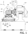
- Fig. 1 is a front view of a mechanism part 10 of an electrodynamic triaxial oscillating device 1 (Hereinafter abbreviated to "oscillating device 1.") embodying the present invention.
- a left right direction in Fig. 1 is referred to as X-axis direction (with the left direction as X-axis positive direction)
- an up-down direction in Fig. 1 is referred to as Z-axis direction (with the upward direction as Z-axis positive direction)
- a direction perpendicular to the paper in Fig. 1 is referred to as Y-axis direction (with a direction going from the backside to the front side of the paper as Y-axis positive direction).
- the Z-axis direction is a vertical direction
- the X-axis direction and the Y-axis direction are horizontal directions.
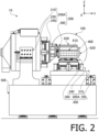
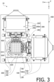
- Fig. 2 and Fig. 3 are a left side view and a plan view of the mechanism part 10 of the oscillating device 1, respectively.
- the mechanism part 10 of the oscillating device 1 includes a substantially box-like vibrating table 400 to which a specimen (not shown) is to be fixed in a state where the specimen is housed inside the vibrating table 400, three oscillating units (X-axis oscillating unit 100, Y-axis oscillating unit 200 and Z-axis oscillating unit 300) which oscillate the vibrating table 400 in the X-axis direction, the Y-axis direction and the Z-axis direction, respectively, and a device base 500 to which the oscillating units 100, 200 and 300 are attached.
- X-axis oscillating unit 100, Y-axis oscillating unit 200 and Z-axis oscillating unit 300 which oscillate the vibrating table 400 in the X-axis direction, the Y-axis direction and the Z-axis direction, respectively.
- the oscillating units 100, 200 and 300 are linear motion oscillating units each including an electrodynamic actuator (voice coil motor).
- the X-axis oscillating unit 100 is coupled to the vibrating table 400 via a biaxial slider (YZ slider 160) being a slide coupling mechanism.
- the YZ slider 160 is configured to be able to accurately transmit vibration of the X-axis oscillating unit 100 to the vibrating table 400 while permitting relative movement (sliding) between the X-axis oscillating unit 100 and the vibrating table 400 in two directions (Y-axis direction and Z-axis direction) orthogonal to an oscillating direction (X-axis direction) of the X-axis oscillating unit 100.
- the Y-axis oscillating unit 200 and the Z-axis oscillating unit 300 are coupled to the vibrating table 400 via a ZX slider 260 and an XY slider 360 being biaxial sliders, respectively.
- the oscillating device 1 is capable of oscillating the vibrating table 400 and the specimen fixed to the vibrating table 400 in the three orthogonal axis directions simultaneously and independently using the oscillating units 100, 200 and 300.
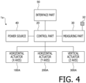
- Fig. 4 is a block diagram showing a brief configuration of a drive control system 1a of the oscillating device 1.
- the drive control system 1a includes a control part 20 configured to control operations of the whole device, a measuring part 30 configured to measure vibration of the vibrating table 400, a power source 40 configured to supply electrical power to each part of the oscillating device 1, and an interface part 50 configured to perform input from and output to the outside.
- the interface part 50 includes, for example, one or more of a user interface for performing input from and output to a user, a network interface for connecting with every kind of networks such as a LAN (Local Area Network), and every kind of communication interfaces such as a USB (Universal Serial Bus) or a GPIB (General Purpose Interface Bus) for connecting with outside devices.
- the user interface includes, for example, one or more of every kind of manipulation switches, indicators, every kind of display devices such as an LCD (Liquid Crystal Display), every kinds of pointing devices such as a mouse or a touch-pad, and every kind of input and output devices such as touch screens, video cameras, printers, scanners, buzzers, speakers, microphones and memory card readers and writers.
- the measuring part 30 includes a triaxial vibration sensor (triaxial vibration pickup) 32 attached to the vibrating table 400, and performs amplification and digital conversion to signals outputted by the triaxial vibration sensor 32 (e.g., acceleration signals or velocity signals) and sends them to the control part 20. It is noted that the triaxial vibration sensor 32 detects vibrations in the X-axis direction, the Y-axis direction and the Z axis direction independently.
- a triaxial vibration sensor triaxial vibration pickup
- the measuring part 30 calculates every kind of parameters indicating a vibrating state of the vibrating table 400 (e.g., including one or more of velocity, acceleration, jerk, acceleration level (vibration level), amplitude, power spectral density and the like) on the basis of the signals from the triaxial vibration sensor 32 and sends them to the control part 20.
- the control part 20 can oscillate the vibrating table 400 in desired amplitudes and frequencies by controlling magnitudes and frequencies of alternating currents to be inputted to a drive coil of each of the oscillating units 100, 200 and 300 (which will be described later) on the basis of oscillation waveforms input via the interface part 50 and/or data input from the measuring part 30.
- the X-axis oscillating unit 100 and the Y-axis oscillating unit 200 includes horizontal drive electrodynamic actuators (Hereinafter simply referred to as “horizontal actuator.") 100A and 200A, respectively.
- the Z-axis oscillating unit 300 includes a vertical drive electrodynamic actuator (Hereinafter simply referred to as “vertical actuator.”) 300A.
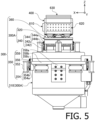
- Figs. 5 , 6 and 7 are a front view, left side view and plan view of the Z-axis oscillating unit 300 (and the vibrating table 400), respectively.
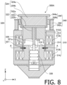
- the vertical actuator 300A includes an air spring 330 ( Fig. 8 ) for supporting weights (static loads) of the specimen and the vibration table.
- the horizontal actuators 100A and 200A include neutral spring mechanisms 130 ( Fig. 11 ) and 230 (not shown), respectively, that apply restoring forces for bringing the vibrating table back to a neutral position (origin, reference position). Since the configurations of the horizontal actuators 100A and 200A are identical to the vertical actuator 300A apart from the neutral spring mechanisms 130 and 230 being provided instead of the air spring 330 and specific structures of a supporting unit 350 and supporting units 150, 250, which will be described later, differing from each other, the detailed configuration of the vertical actuator 300A will be described on behalf of each of the actuators.
- the vertical actuator 300A includes a fixing part 310 having a tubular body 312 and a movable part 320 of which a lower portion thereof is accommodated inside the tube of the fixing part 310.
- the movable part 320 can move in the vertical direction (Z-axis direction) with respect to the fixing part 310.
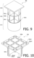
- Fig. 9 is an external view showing a brief configuration of the movable part 320.
- the movable part 320 includes a main frame 322 having a substantially cylindrical shape, a drive coil 321 coaxially attached to a lower end portion of the main frame 322, and a rod 326 ( Fig. 8 ) extending downward from the center of a lower surface of the main frame. Also, an expansion frame 324 having a diameter substantially equal to a diameter of the main frame 322 is coaxially attached to an upper end portion of the main frame 322.
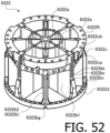
- the main frame 322 includes a substantially disk-shaped top plate 322a arranged perpendicularly to the drive direction (Z-axis direction), a tubular main column 322c extending perpendicularly (in the drive direction) from the center of a lower surface of the top plate 322a, and eight ribs 322b, each having a substantially rectangular flat plate shape, radially attached to an outer periphery of the main column 322c.
- the eight ribs 322b are arranged around the main column 322c at regular intervals in a circumferential direction.
- top plate 322a and the main column 322c By coupling the top plate 322a and the main column 322c with the eight ribs 322b arranged as described above, sufficient rigidity is given to the main frame 322.
- the top plate 322a, the ribs 322b and the main column 322c are integrally coupled to each other by welding or the like.
- each of the ribs 322b protrudes downwardly and forms a coil attaching part 322d.
- the coil attaching parts 322d of the eight ribs 322b are inserted into an upper end portion of the drive coil 321, and the drive coil 321 is attached to the main frame 322.
- the rod 326 is fitted from below. A lower portion of the rod 326 protrudes downwardly from the main column 322c. Also, to the top plate 322b, the expansion frame 324 is attached.
- Fig. 10 is an external view of the expansion frame 324.
- the expansion frame 324 includes a torso portion 324a having a diameter substantially equal to the diameter of the main frame 322, and a top plate 324b attached horizontally on an upper end of the torso portion 324a.
- the top plate 324b is a member having a substantially rectangular flat plate shape with a width (dimension in the X-axis direction) and a depth (dimension in the Y-axis direction) equal to or larger than the outer diameter of the torso portion 324a.
- the top plate 324b of the expansion frame 324 On an upper surface of the top plate 324b of the expansion frame 324, six streaks of grooves (pairs of perpendicular level differences 324b1) extending in a lattice in the X-axis direction and the Y-axis direction are formed.
- rails 364a of as many as one half the number of the XY sliders 360 (in the present embodiment, nine rails), which will be described later, are arranged. That is, the level differences 324b1 are positioning structures for attaching the rails 364a at accurate positions on the top plate 324b.
- the expansion frame 324 is fixed to the main frame 322 with bolts in a state where the top plate 322a of the main frame 322 is fitted in this recess 324a3.
- a substantially tubular shaped inner magnetic pole 316 arranged coaxially with the tubular body 312 is fixed inside the tubular body 312 of the fixing part 310.
- the tubular body 312 and the inner magnetic pole 316 are both formed of magnetic substances.
- An outer diameter of the inner magnetic pole 316 is smaller than an inner diameter of the drive coil 321, and the drive coil 321 is arranged in a gap between an outer peripheral surface of the inner magnetic pole 316 and an inner peripheral surface of the tubular body 312.
- a bearing 318 configured to support the rod 326 movably only in the Z-axis direction is fixed.
- a plurality of recesses 312b are formed on the inner peripheral surface 312a of the tubular body 312, and an excitation coil 314 is accommodated in each of the recesses 312b.
- direct current exciting current
- magnetic fields in radial directions of the tubular body 312 such as shown in arrows A are generated at positions where the inner peripheral surface 312a of the tubular body 312 and the outer peripheral surface of the inner magnetic pole 316 are closely opposing to each other.
- a drive current is supplied to the drive coil 321 in this state, Lorentz force acting in the axial direction of the drive coil 321, that is, in the Z-axis direction, is generated and the movable part 320 is driven in the Z-axis direction.
- the air spring 330 is accommodated in the tube of the inner magnetic pole 316. A lower end of the air spring 330 is fixed to the tubular body 312. Also, a flange portion formed on the rod 326 is placed on and upper surface of the air spring 330. That is, the air spring 330 supports the main frame 322 from below via the rod 326. More specifically, weights (static loads) of the movable part 320 and the XY slider 360, the vibrating table 400, an X-axis counter balancer 610, a Y-axis counter balancer part 620 and a Z-axis counter balancer 630 which will be described later, and the specimen supported by the movable part 320 are supported by the air spring 330.
- the need to support the weights (static loads) of the movable parts 320, the vibrating table 400 and the like by the drive force (Lorentz force) of the Z-axis oscillating unit 300 is eliminated by providing the air spring 330 to the Z-axis oscillating unit 300 and only dynamic load for oscillating the movable part 320 and the like needs to be supplied, and thus drive current to be supplied to the Z-axis oscillating unit 300 (i.e., power consumption) is reduced.
- the drive coil 321 can be downsized due to the reduction of the necessary drive force, the weight of the movable part 320 can be reduced and thus the Z-axis oscillating unit 300 can be driven in a higher frequency.
- the power source 40 since the need to supply a large direct current component for supporting the weights of the movable part 320, the vibrating table 400 and the like to the drive coil 321 is eliminated, a power source having a smaller and simpler configuration can be adopted as the power source 40.
- the fixing part 310 when the movable part 320 of the Z-axis oscillating unit 300 is driven, the fixing part 310 also receives a strong reaction force (oscillating force) in the drive axis (Z-axis) direction.
- the oscillating force transmitted from the movable part 320 to the fixing part 310 is alleviated by providing the air spring 330 between the movable part 320 and the fixing part 310. Therefore, for instance, vibration of the movable part 320 is prevented from being transmitted to the vibrating table 400 via the fixing part 310, the device base 500 and the oscillating units 100 and 200 as noise components.
- the horizontal actuator 100A differs from the vertical actuator 300A in that the horizontal actuator 100A includes the neutral spring mechanism 130 ( Fig. 11 ) instead of the air spring 330 ( Fig. 8 ) and in the specific structures of the supporting unit 150, but other basic configurations are in common.
- the neutral spring mechanism 130 is a cushioning device that elastically couples a fixing part 110 and a movable part 120 of the horizontal actuator 100A.
- the horizontal actuator 200A has the same configuration as the horizontal actuator 100A described below.
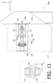
- Fig. 11 is an enlarged longitudinal section view around the neutral spring mechanism 130 of the horizontal actuator 100A. Inside a broken line frame is a back view of the neutral spring mechanism 130 viewed toward the X-axis positive direction.
- the neutral spring mechanism 130 includes an U-shaped stay 131, a rod 132, a nut 133 and a pair of compression coil springs 134 and 135 (elastic component).
- the U-shaped stay 131 is fixed to the bottom portion of the fixing part 110 (right end portion in Fig. 11 ) at flange portions 131a formed at both ends of the U-shape. Also, at the center of a bottom portion 131b of the U-shaped stay 131 (left end portion in Fig. 11 ), a through hole 131b1 through which the rod 132 extending in the X-axis direction is inserted is provided.
- a flange portion 132b is provided at an end (left end in Fig. 11 ) of the rod 132, and the rod 132 is coupled to a tip (right end in Fig. 11 ) of a rod 122a of the movable part 120 via the flange portion 132b. Also, a male screw portion 132a that engages with the nut 133 is formed on the other end portion (right end portion in Fig. 11 ) of the rod 132.
- the pair of the coil springs 134 and 135 are put on the rod 132.
- One coil spring 134 is retained by being nipped between a flange portion of the nut 133 and the bottom portion 131b (elastic component supporting plate) of the U-shaped stay 131.
- the other coil spring 135 is retained by being nipped between the bottom portion 131b of the U-shaped stay 131 and the flange portion 132b of the rod 132.
- a preload is applied to the pair of the coil springs 134 and 135 by the tightening of the nut 133.
- a position where restoring forces of the pair of the coil springs 134 and 135 balance is a neutral position (or origin or reference position) of the movable part 120 of the horizontal actuator 100A in the movable direction (X-axis direction).
- a neutral position or origin or reference position
- a restoring force that moves the movable part 120 back to the neutral position acts on the movable part 120 by the neutral spring mechanism 130 (directly by the pair of the coil springs 134 and 135). Accordingly, it becomes possible to reciprocally drive the movable part 120 in the X-axis direction with the neutral position always as the reference position of the reciprocation, and thus a problem that a position of the movable part 120 sways while driving is overcome.
- the movable part 320 of the vertical actuator 300A is supported from the sides thereof movably only in the drive direction (Z-axis direction) by four movable part support mechanisms 340 arranged at regular intervals around the movable part 320.
- the movable part support mechanism 340 includes an angle plate 342 and a Z-axis linear guide 344.
- the Z-axis linear guide 344 includes the Z-axis rail 344a and a Z-axis carriage 344b.
- a linear guide having a configuration identical to an A-type linear guide 364A ( Figs. 14-19 ) which will be described later is used.
- a linear guide is a mechanism that guides a linear motion, and the Z-axis linear guide 344 guides a linear motion in the Z-axis direction.
- two pairs of the movable part support mechanisms 340 are arranged to respectively oppose to each other in horizontal directions forming an angle of 45 degrees with respect to the X-axis direction and the Y-axis direction, but for convenience of explanation, in other drawings, the two pairs of the movable part support mechanisms 340 are shown to oppose in the X-axis direction and the Y-axis direction, respectively. Also, the number and arrangement of the movable part support mechanisms 340 are not limited to those described, but, for example, configurations in which the movable part 320 is supported by three or more sets of the movable part support mechanisms 340 arranged substantially at regular intervals around the movable part 320 are preferable.
- the angle plate 342 is a fixing member having an U-shaped (or L-shaped) cross-section and reinforced with a rib. To a vertical portion 342u of each of the angle plates 342, the Z-axis carriage 344b that engages with the Z-axis rail 344a is fixed.
- the Z-axis carriage 344b has a plurality of balls RE (which will be described later) as rolling bodies and configures the Z-axis linear guide 344, being a rolling guide, together with the Z-axis rail 344a. That is, the movable part 320 is supported slidably only in the Z-axis direction, at the upper portion of the expansion frame 324, from its sides by four sets of supporting structures (movable part support mechanisms 340) each constituted of the angle plate 342 and the Z-axis linear guide 344 and is configured not to move in the X-axis direction and the Y-axis direction. Therefore, cross talks that occur due to vibrations of the movable part 320 in the X-axis direction and the Y-axis direction are prevented.
- balls RE which will be described later
- the movable part 320 can move smoothly in the Z-axis direction by the use of the Z-axis linear guide 344 (rolling guide). Furthermore, since, as described above, the movable part 320 is also supported, at its lower portion, by the bearing 318 movably only in the Z-axis direction, rotations about the X axis, the Y axis and the Z axis are also restricted, and thus unnecessary vibrations (vibrations other than the controlled translation in the Z-axis direction) hardly occur.
- the rail is attached to the fixed side, and the carriage is attached to the movable side.
- the Z-axis rail 344a is attached to the movable part 320 and the Z-axis carriage 344b is attached to the angle plate 342. Unnecessary vibrations are suppressed by adopting such an anomalous attachment structure.
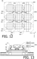
- Fig. 12 is a plan view illustrating the configuration of the XY slider 360.
- the XY slider 360 consists of nine cross guides 364 (364L1-L3, 364M1-M3, 364R1-R3) arranged at regular intervals in the X-axis direction and the Y-axis direction.
- Each of these nine cross guides 364 couples the Z-axis oscillating unit 300 (specifically, the movable part 320 of the vertical actuator 300A) and the vibrating table 400 slidably in the X-axis direction and the Y-axis direction with low resistance.
- Fig. 13 is a side view of the cross guide 364.
- the cross guide 364 is a cross guide in which top faces of carriages of an A-type linear guide 364A and a B-type linear guide 364B are superimposed and fixed together such that their movable directions bisect at right angles.
- a mass distribution in a length (L) direction and a mass distribution in a width (W) direction differ from each other, and this may become a factor that causes a directionality in oscillating performance of the oscillating device 1.
- the carriages of the A-type linear guide 364A and the B-type linear guide 364B are directly fixed together while orienting the length direction of one of the two in the width direction of the other to form a cross carriage (a carriage of the cross guide 364). Due to this configuration, the mass distribution directionalities of the A-type linear guide 364A and the B-type linear guide 364B are offset to respectable degrees and thereby a cross carriage with small mass distribution directionality can be obtained. The directionality in the oscillating performance of the oscillating device 1 is alleviated by using such cross carriages. Details of the A-type linear guide 364A and the B-type linear guide 364B will be described later.
- Fig. 12 among a pair of linear guides (an X-axis linear guide 364X slidable in the X-axis direction and a Y-axis linear guide 364Y slidable in the Y-axis direction) configuring each cross guide 364, the one arranged on the vibrating table 400 side is indicated with solid lines, and the one arranged on the Z-axis oscillating unit 300 side is indicated with broken lines.
- first orientation cross guides 364P cross guides 364M1, 364L2, 364R2, 364M3 of which the X-axis linear guides 364X are attached to the vibrating table 400
- second orientation cross guides 364 cross guides 364L1, 364R1, 364M2, 364L3, 364R3 of which the Y-axis linear guides 364Y are attached to the vibrating table 400 are mixed. Furthermore, in each of the X-axis direction and the Y-axis direction, orientations of adjacent cross guides 364 are made to alternate.
- first orientation cross guides 364P and the second orientation cross guides 364 are alternately arranged in each of the X-axis direction and the Y-axis direction.
- the mass distribution directionalities of the cross guides 364 are averaged and thereby the oscillating performance with smaller directionality is realized.
- Fig. 14, Fig. 15 and Fig. 16 are a plan view, a side view and a front view of the A-type linear guide 364A (B-type linear guide 364B), respectively.
- the A-type linear guide 364A (B-type linear guide 364B) includes a rail 364a and an A-type carriage 364b/A (B-type carriage 364b/B).
- the A-type carriage 364b/A (B-type carriage 364b/B) is provided with four attachment holes HA (attachment holes HB), being tapped holes (drilled holes) for fixing bolts, at four corners of a top face of the carriage. Structures of the A-type carriage 364b/A and the B-type carriage 364b/B are identical except for types of the attachment holes HA, HB.
- the four attachment holes HA, HB are formed such that their center lines touch respective corners of a square Sq (shown in a chain line in Fig. 14 ) on the top face of the carriage. That is, intervals (lengths of sides of the square Sq) at which the attachment holes HA of the A-type carriage 364b/A are formed coincide with intervals at which the attachment holes HB of the B-type carriage 364b/B are formed, and the arrangements of the attachment holes HA, HB each have four times rotation symmetry.
- the A-type linear guide 364b/A and the B-type linear guide 364b/B are configured such that, even if the A-type linear guide 364b/A and the B-type linear guide 364b/B are superimposed while shifting their moving directions to each other by 90 degrees, the four attachment holes HA and the four attachment holes HB respectively communicate, thereby making it possible to couple the A-type carriage 364b/A and the B-type carriage 364b/B by 4 bolts.
- the attachment holes HA of the A-type carriage 364b/A are formed as tapped holes and the attachment holes HB of the B-type carriage 364b/B are formed as drilled holes, the A-type carriage 364b/A and the B-type carriage 364b/B can be coupled directly with each other without using a coupling plate.
- a rigidity of the cross guide 364 increases (i.e., eigenfrequency of the cross guide 364 increases) and thereby the oscillating performance of the oscillating device 1 improves. Specifically, it becomes possible to oscillate up to a higher frequency with less vibration noises.
- electrical power needed to oscillate the cross guide 364 i.e., to drive the mechanism part 10.
- An L-shaped notch C1 is formed at each of the four corners of the top face of the carriage of the A-type carriage 364b/A (B-type carriage 364b/B). Furthermore, a pair of L-shaped notches C2 extending in the moving direction are formed at lower portions of both sides in a width direction (up-down direction in Fig. 14 ) of the A-type carriage 364b/A (B-type carriage 364b/B). That is, apart from flange portions F overhanging from both sides in the width direction where the attachment holes HA (attachment holes HB) are formed, both side edges of the A-type carriage 364b/A (B-type carriage 364b/B) in the width direction are cut off. By these configurations, weight reduction of the A-type carriage 364b/A (B-type carriage 364b/B) is realized.
- the cross guide 364 consists only of the A-type linear guide 364A and B-type linear guide 364B for cross guides and four bolts for coupling the A-type linear guide 364A and B-type linear guide 364B, the cross guide 364 is small, lightweight and have a high rigidity. Therefore, a resonance frequency of the cross guide 364 is high, making it possible to realize an XY slider (slide coupling mechanism) with less vibration noises.
- the A-type carriage 364b/A and the B-type carriage 364b/B have the same structure. Therefore, by coupling the A-type linear guide 364A and the B-type linear guide 364B while shifting their moving directions to each other by 90 degrees, the mass distribution directionalities of each of the linear guides in the length (L) direction and in the width (W) direction are offset, and thereby a cross guide 364 with small mass distribution directionality is realized.
- each of the carriage 364b/A and 364b/B has substantially two times rotation symmetry around an axis in an up-down direction (direction perpendicular to the paper in Fig. 14 ) but does not have four times rotation symmetry. Therefore, response characteristics of each of the carriages 364b/A, 364b/B to external forces in the moveable direction (left-right direction in Fig. 14 ) and in a lateral direction (up-down direction in Fig. 14 ) are different.
- the vibrating table 400 is coupled to the movable part 320 of the Z-axis oscillating unit 300 slidably in the X-axis direction and the Y-axis direction.
- Fig. 17 is a cross sectional view of the A-type linear guide 364A.
- Fig. 18 is a diagram showing of a section I-I of Fig. 17 .
- the A-type linear guide 364A is a linear guide of which the number of balls RE (the number of effective balls) being rolling bodies interposed between the rail and the carriage is increased to equal to or more than twice the ordinary number of balls by decreasing an outer diameter of the ball RE to about a half the ordinary outer diameter and by setting the number of load paths for the rolling bodies to eight streaks which is twice the ordinary number of load paths.
- the A-type carriage 364b/A includes a main block 364b1/A, a pair of end blocks 364b2 attached on both sides of the main block 364b 1/A in the moving direction, and four rod members R1, R2, R3, R4 respectively inserted in four cylindrical through holes h1, h2, h3, h4 penetrating through the main block 364b1/A in the moving direction.
- the rod members R1, R2, R3, R4 are members having the same configuration.
- the main block 364b1/A is a metal member (e.g., stainless steel), and the end blocks 364b2 and the rod members R1, R2, R3, R4 are resin members. It is noted that materials of each of the members configuring the A-type carriage 364b/A is not limited to those described, and can be properly selected from metals, resins, ceramics or every types of composite materials (e.g., fiber reinforced plastic).
- a load path refers to a portion among a path of the rolling bodies where a load acts on the rolling bodies.
- the load paths P1a and P1b are formed close to each other between the right side face SR of the rail 364a and the main block 364b 1/A.
- the load paths P2a and P2b are formed close to each other between the right top face TR of the rail 364a and the main block 364b1/A.
- the load paths P3a and P3b are formed close to each other between the left top face TL of the rail 364a and the main block 364b1/A.
- the load paths P4a and P4b (load path pair P4) are formed close to each other between the left side face SL of the rail 364a and the main block 364b1/A.
- the pair of paths for the rolling bodies that are formed in parallel and close to each other as described above will be hereinafter referred to as a "path pair.”
- gapsP1c, P2c, P3c, P4c are respectively formed between the right side face SR, right top face TR, left top face TL and left side face SL of the rail 364a and the main block 364b1/A.
- the load path pairs P1, P2, P3, P4 are respectively formed in the gaps P1c, P2c, P3c, P4c.
- the four through holes h1, h2, h3, h4 are formed in parallel with and at positions opposing the respective four load path pairs P1, P2, P3, P4.
- Through holes Qc (Q1c, Q2c, Q3c, Q4c) having substantially rectangular cross sectional shapes pass through the rod members R1, R2, R3, R4 in the length directions, respectively.
- no-load paths Qa QIa, Q2a, Q3a, Q4a
- Qb Q1b, Q2b, Q3b, Q4b
- Gd Reference signs are indicated only to the through hole Q2c.
- recessed parts D1, D2, D3, D4 On the end block 364b2, four recessed parts D1, D2, D3, D4 (Only the recessed part D3 is shown in the drawings.) configured to accommodate respective protruding parts Rp (R1p, R2p, R3p, R4p) are formed.
- recessed part D3 On the recessed part D3, a pair of grooves Gd respectively opposing the pair of grooves Gc formed on the protruding part R3p is formed.
- Two U-shaped turning paths U3a, U3b (Only the path U3a is shown in the drawings.) are formed.
- a pair of the grooves Gd is formed on each of the other three recessed parts D1, D2, D4 as well, and a pair of turning paths U1a and U1b, a pair of turning paths U2a and U2b, and a pair of turning paths U4a and U4b are formed between respective pairs of grooves Gc formed on the protruding parts R1p, R2p, R4p.
- each of the turning paths Ua, Ub is connected to the load path Pa, Pb, and the other end is connected to the no-load path Qa, Qb, respectively. That is, eight streaks of the load paths P1a, P1b, P2a, P2b, P3a, P3b, P4a, P4b and eight streaks of the no-load paths Q1a, Q1b, Q2a, Q2b, Q3a, Q3b, Q4a, Q4b are connected to form loops by the eight turning paths U1a, U1b, U2a, U2b, U3a, U3b, U4a, U4b, thereby forming eight circulating passages.
- the gaps Pc (P1c, P2c, P3c, P4c) and the through holes Qc (Q1c, Q2c, Q3c, Q4c) are connected to form loops by the pairs of U-shaped gaps Gu (Gu1, Gu2, Gu3, Gu4), thereby forming four annular gaps CG.
- the above described four pairs (eight streaks) of circulating passages CP are respectively formed.
- a plurality of balls RE made of stainless steel are accommodated while aligned in a line. Also, a retainer RT in the form of one endless belt is inserted in each of the four annular gaps CG.
- Fig. 19 is a perspective view showing a portion of the retainer RT.
- the retainer RT is a flexible resin member, and a plurality of through holes RTh are formed at regular intervals in two rows in the length direction. An interval between the two rows of the through holes RTh is the same as an interval between the two streaks of circulating passages CP (passage pair) provided in each annular gap CG.
- each of a plurality of the balls RE arranged in the passage pair within the same annular gap CG is rotatably fitted. Then, the retainer RT circulates within the annular gap CG together with a plurality of the balls RE.
- the retainer RT prevents the balls RE from contacting with each other and thereby reduces vibration noises caused by frictions between the balls RE and abrasion of the balls RE.
- a length L of the A-type carriage 364b/A (and B-type carriage 364b/B) is set to be equal to or less than 125 mm (about 120 mm) and thereby an aspect ratio (a ratio L/W of the length L and a width W) is suppressed to be equal to or less than 1.35 (about 1.32).
- the length L of the eight-streak type carriage to be used in the oscillating device is within the range of 70 - 160 mm (more preferably, within the range of 90 - 140 mm, and further preferably, within the range of 110 - 130 mm).
- the aspect ratio L/W is better to be near 1 so that the oscillating performances becomes uniform in every axis directions.
- the aspect ratio L/W of the eight-streak type carriage is within the range of 0.65 - 1.5 (more preferably, within the range of 0.7 - 1.4, and further preferably, within the range of 0.75 - 1.35).
- the number of streaks of the circulating passages CP is set to eight which is twice the ordinary number of streaks by decreasing the outer diameter of the ball RE to about a half the ordinary outer diameter. Furthermore, the number of balls RE arranged in the load paths is also increased to nearly twice the ordinary number of balls RE. As a result, the A-type carriage 364b/A is more dispersedly supported by equal to or more than twice (nearly four times) the conventional number of balls RE. As a result, improvement in the rigidity and improvement in the motion accuracy (lowering of waving) are realized.
- A-type linear guide 364A Since the use of eight-streak type linear guides such as the A-type linear guide 364A had been limited to the use for the purpose of improving positional accuracies in machine tools or the like, conventional eight-streak type linear guides have large carriage lengths L of equal to or more than 180 mm, and their aspect ratios are equal to or more than 2.3 indicating that they have bad weight balances. As a result, the conventional eight-streak type linear guides had not been suitable for mechanisms such as oscillating devices which are driven at high speeds.
- the A-type linear guide 364A (B-type linear guide 364B) is made such that the eight-streak type linear guide becomes applicable to oscillating devices by making the carriage length L and the aspect ratio smaller. Also, oscillations with frequencies over 2 kHz, which were conventionally difficult, have become possible by the use of the A-type linear guide 364A.
- Fig. 20 is a side view of the X-axis oscillating unit 100 and the vibrating table 400.
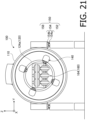
- Fig. 21 is a front view of the X-axis oscillating unit 100.
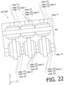
- Fig. 22 is a front view of the YZ slider 160.
- Fig. 23 is a plan view around the vibrating table 400.
- the YZ slider 160 includes a coupling arm 162 fixed to a tip face of the movable part 120 (expansion frame 124) of the X-axis oscillating unit 100, and a cross guide part 164 coupling the coupling arm 162 and the vibrating table 400 slidably in the y-axis direction and the Z-axis direction.
- the cross guide part 164 includes two Y-axis rails 164a/Y (164alY1, 164a/Y4), six Z-axis rails 164a/Z (164alZ1, 164a/Z2, 164a/Z3, 164a/Z4, 164a/Z5, 164a/Z6), and six cross carriages 164b (164b/1, 164b/2, 164b/3, 164b/4, 164b/5, 164b/6) which couple the Y-axis rails 164a/Y and the Z-axis rails 164a/Z slidably in the Y-axis direction and the Z-axis direction.
- the six cross carriages 164b are arranged in a lattice (Y-axis direction: three rows, Z-axis direction: two rows).
- Three Z-axis rails 164alZ1, 164a/Z2, 164a/Z3 on the upper row and one Y-axis rail 164a/Y4 on the lower row are fixed to the tip face of the coupling arm 162. Also, the remaining three Z-axis rails 164a/Z4, /Z5, /Z6 on the lower row and one Y-axis rail 164a/Y1 on the upper row are fixed to a side face of the vibrating table 400.
- the cross carriage 164b/1 is a cross carriage in which the Y-axis carriage 164b/Y1 which engages with the Y-axis rail 164alY1 and a Z-axis carriage 164b/Z1 which engages with the Z-axis rail 164alZ1 are superimposed back to back (i.e., the top faces of the carriages are superimposed with each other) and fixed.
- One of the Y-axis carriage 164b/Y1 and the Z-axis carriage 164b/Z1 has the same configuration as the above-described A-type carriage 364b/A, and the other has the same configuration as the above-described B-type carriage 364b/B.
- the Y-axis carriage 164b/Y1 and the Z-axis carriage 164b/Z 1 are directly fixed together only with four bolts without using an attaching plate.
- All the three cross carriages 164b/1, 164b/2, 164b/3 on the upper row engage with one Y-axis rail 164alY1 on the upper row, and engage with three Z-axis rails 164alZ1, 164a/Z2, 164a/Z3 on the upper row, respectively.
- all the three cross carriages 164b/4, 164b/5, 164b/6 on the lower row engage with one Y-axis rail 164a/Y4 on the lower row, and engage with three Z-axis rails 164a/Z4, 164a/Z5, 164a/Z6 on the lower row, respectively.
- the vibrating table 400 is coupled to the movable part 120 of the X-axis oscillating unit 100 slidably in the Y-axis direction and the Z-axis direction by the configuration of the YZ slider 160 described above.
- the ZX slider 260 which couples the Y-axis oscillating unit 200 and the vibrating table 400 also has the same configuration as the YZ slider 160, and the vibrating table 400 is coupled to the movable part 220 of the Y-axis oscillating unit 200 slidably in the Z-axis direction and the X-axis direction. Therefore, vibration components of the vibrating table 400 in the Z-axis direction and the X-axis direction will not be transmitted to the Y-axis oscillating unit 200 even if the vibrating table 400 is vibrated in the Z-axis direction and the X-axis direction by the Z-axis oscillating unit 300 and the X-axis oscillating unit 100, respectively.
- the oscillating units 100, 200, 300 can accurately oscillate the vibrating table 400 in respective driving directions without interfering with each other. Also, since the movable part of each of the oscillating units 100, 200, 300 is supported movably only in the driving direction by the movable part support mechanism, the oscillating units 100, 200, 300 hardly vibrate in the non-driving directions. Therefore, uncontrolled vibrations in the non-driving directions do not act on the vibrating table 400 from the oscillating units 100, 200, 300. Accordingly, vibration of the vibrating table 400 in each axis direction is accurately controlled by the driving of the corresponding one of the oscillating units 100, 200, 300.
- the vibrating table 400 is configured such that its center of gravity substantially coincides with the center of its outer dimension so as to suppress occurrence of unnecessary rotational motion (rotational vibration).
- the biaxial sliders YZ slider 160, ZX slider 260, XY slider 360
- portions of the biaxial sliders are fixed to the vibrating table 400 (more precisely, portions of the biaxial sliders are restrained by the vibrating table 400 and move along with the vibrating table 400)
- the center of gravity of the oscillated portion shifts from the center of the vibrating table 400.
- This bias in the center of gravity of the oscillated portion causes rotational vibration of the vibrating table 400 and, as a result, causes variations in vibrating states (e.g., acceleration) according to positions on the vibrating table 400.
- counter balancers which compensate the imbalance caused by the biaxial sliders are provided to the vibrating table 400 on the opposite sides of the biaxial sliders such that the center of gravity of the oscillated portion (the vibration table 400, the counter balancers and the portions of the biaxial sliders) substantially coincides with the center of the vibrating table 400.
- an X-axis counter balancer 610 (first counter balancer) is provided on a side face of the vibrating table 400 opposite to the side face on which the YZ slider 160 is attached (i.e., the side face on the X-axis positive direction side).
- a Y-axis counter balancer 620 (second counter balancer) is provided on a side face of the vibrating table 400 opposite to the side face on which the ZX slider 260 is attached (i.e., the side face on the Y-axis positive direction side). It is noted that the Y-axis counter balancer 620 of the present embodiment has the same configuration as the X-axis counter balancer 610.
- a Z-axis counter balancer 630 (third counter balancer) is provided.
- Fig .25 is a sectional view of the X-axis counter balancer 610 (and the Y-axis counter balancer 620). It is noted that the X-axis counter balancer 610 includes a cushioning layer 611 (cushioning part) and a weight plate 612 (weight part). The cushioning layer 611 is pinched between the weight plate 612 and the side face of the vibrating table 400 and fastened.
- the weight plate 612 is a member for providing a mass for compensating an imbalance of the oscillated portion caused by the attachment of the biaxial slider to the vibrating table 400.
- a thickness of the weight plate 612 of the present embodiment is 20 mm.
- the cushioning layer 611 blocks transmission of vibration noises with frequencies higher than an oscillating frequency between the weight plate 612 and the vibrating table 400. Also, the cushioning layer 611 prevents occurrence of chattering between the vibrating table 400 and the weight plate 612.
- the weight plate 612 and the cushioning layer 611 are attached to the side face of the vibrating table 400 with a plurality of bolts 613. Tapped holes 400h are formed on the side face of the vibrating table 400, and through holes 612c are formed on the weight plate 612.
- the weight plate 612 and the cushioning layer 611 are fastened to the side face of the vibrating table 400 by inserting the bolts 613 in the through holes 612c and screwing them in the tapped holes 400h. It is noted that through holes communicating with the through holes 612c and the screw holes 400h are formed on the cushioning layer 611 as well.
- a plurality of through holes 612c are formed in a lattice point in two orthogonal directions (Y-axis direction and Z-axis direction) at regular intervals P.
- the intervals P between the through holes 612c are 50 mm.
- the occurrence of the chattering can be effectively suppressed by shortening the intervals P between the through holes 612c (by setting the intervals P preferably to equal to or less than 100 mm, and more preferably to equal to or less than 50 mm).
- Fig. 26 is a sectional view of the Z-axis counter balancer 630.
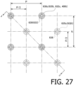
- Fig. 27 is an enlarged plan view showing bolt fixing positions of the Z-axis counter balancer 630. It is noted that Fig. 26 a sectional view in J-J of Fig. 27 .
- the Z-axis counter balancer 630 includes a first cushioning layer 631 (first cushioning part), a first weight plate 632 (first weight part), a second cushioning layer 634 (second cushioning part), a second weight plate 635 (second weight part), a third cushioning layer 637 (third cushioning part), and a third weight plate 638 (third weight part).
- the first cushioning layer 631, the first weight plate 632, the second cushioning layer 634, the second weight plate 635, the third cushioning layer 637 and the third weight plate 638 are stacked on the top face of the vibrating table 400 in this order.
- the first weight plate 632, the second weight plate 635 and the third weight plate 638 are members for providing masses for compensating the imbalance of the oscillated portion caused by the attachment of the biaxial slider to the vibrating table 400 and, in the present embodiment, they are plate members made of aluminum alloy. In the present embodiment, thicknesses of the first weight plate 632, the second weight plate 635 and the third weight plate 638 are 30 mm, 20 mm and 10 mm, respectively. It is noted that a width (X-axis direction) and a depth (Y-axis direction) of the vibrating table 400 of the present embodiment are 500 mm, and a width and a depth of the Z-axis counter balancer 630 are 400 mm.
- the first cushioning layer 631, the second cushioning layer 634 and the third cushioning layer 637 lower transmission of vibration noises with frequencies higher than an oscillating frequency between the first weight plate 632 and the vibrating table 400 or between adjacent weight plates 632, 635, 638, respectively. Also, the first cushioning layer 631, the second cushioning layer 634 and the third cushioning layer 637 prevent occurrence of chattering between the vibrating table 400 and the first weight plate 632 or between adjacent weight plates 632, 635, 638.
- a plurality of through holes 632c and a plurality of tapped holes 632t are respectively formed in lattice points in two orthogonal directions (X-axis direction and Y-axis direction) at regular intervals (in the present embodiment, at intervals P which are the same as those for the through holes 612c of the X-axis counter balancer 610). It is noted that, as shown in Fig. 27 , positions of the through holes 632c and the tapped holes 632t are shifted by P/2 in each arranging direction. That is, in the plan view, the tapped hole 632t is formed at an intermediate position of four through holes 632c.
- the first weight plate 632 and the first cushioning layer 631 are fastened to the top face of the vibrating table 400 by inserting bolts 633 in the through holes 632c and screwing them in tapped holes 400h formed on the top face of the vibrating table 400.
- a plurality of through holes 635c and a plurality of tapped holes 635t are respectively formed in lattice points in two orthogonal directions (X-axis direction and Y-axis direction) at regular intervals P as well. Positions of the through holes 635c and the tapped holes 635t are shifted by P/2 in each arranging direction.
- the second weight plate 635 and the second cushioning layer 634 are fastened to a top face of the first weight plate 632 by inserting bolts 636 in the through holes 635c and screwing them in the tapped holes 632t formed on the top face of the first weight plate 632.
- the third weight plate 638 and the third cushioning layer 637 are fastened to a top face of the second weight plate 635 by inserting bolts 639 in the through holes 638c and screwing them in the tapped holes 635t formed on the top face of the second weight plate 635.
- the Z-axis counter balancer 630 is made capable of effectively suppressing vibration noises even if a specimen, being a heavy load, are put on the Z-axis counter balancer 630.
- each of the weight plates 612, 632, 635, 638 is not limited to the rectangular flat plate shape, but can be formed in various shapes. For example, by making the shape to correspond to the shape (mass distribution) of the biaxial sliders, it becomes possible to compensate the imbalance with high accuracy.
- each of the weight plates 632, 635, 638 may be changed in accordance with a mass of the specimen, oscillating conditions or the like.
- the thicknesses of all the weight plates 632, 635, 638 may be made the same.
- the thicknesses of the weight plates may be made thicker as the layer goes up, or the intermediate weight plate 635 may be made the thickest.
- each of the weight plates 612, 632, 635, 638 besides typical structure materials such as aluminum alloys or steel, lead, copper, metal foams, resins (including plastics and rubbers), fiber reinforced plastics or the like having vibration absorbing property may be used.
- typical structure materials such as aluminum alloys or steel, lead, copper, metal foams, resins (including plastics and rubbers), fiber reinforced plastics or the like having vibration absorbing property may be used.
- each of the cushioning layers 611, 631, 634, 637 is decided within the range of 0.5 mm to 2 mm in accordance with masses of the weight plates, materials and characteristics of the cushioning layers, a size of the oscillating device 1, test conditions or the like. If the cushioning layers are made too thick, the weight plates become prone to resonate and oscillating performances at low frequency ranges degrade. Furthermore, if the cushioning layers are made too thin, enough vibration noise suppressing effect cannot be obtained.
- sheets of various materials such as various synthetic resins (e.g., plastics such as polyolefin, polyvinyl chloride, polyamide, PEEK (polyether ether ketone), polycarbonate and polytetrafluoroethylene), various elastomers (vulcanized rubbers such as natural rubbers and various synthetic rubbers, thermosetting elastomers such as urethane rubbers and silicone rubbers, and thermoplastic elastomers), silicone gel (low crosslinking density silicone resins), various polymer alloys, fiber reinforced plastics, resin foams, soft metals such as lead, and metal foams or felt (nonwoven fabrics) may be used.
- various synthetic resins e.g., plastics such as polyolefin, polyvinyl chloride, polyamide, PEEK (polyether ether ketone), polycarbonate and polytetrafluoroethylene
- various elastomers vulcanized rubbers such as natural rubbers and various synthetic rubbers, thermosetting elastomers such
- the cushioning layers may be formed by providing gaps between the vibrating table 400 and the weight plates 612, 632 (or between adjacent weight plates 632, 635, 638) and filling the gaps with adhesives or caking materials and curing them.
- the Z-axis counter balancer 630 of the present embodiment has the configuration in which three layers of the cushioning layers and the weight plates are alternately laminated, but may have a configuration in which two layers or four or more layers are laminated. Furthermore, the materials and/or the thicknesses of the cushioning layers and/or the weight plates may be changed for each layer.
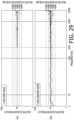
- Figs. 28-30 are graphs showing relative acceleration spectrum characteristics measured at four points on the vibrating table 400 (more precisely, on the Z-axis counter balancer 630). Also, Fig. 31 is a diagram showing monitoring points (acceleration measurement points) on the Z-axis counter balancer 630.
- the oscillating device 1 is designed such that a reference point MP0, which is at the center of the top face of the Z-axis counter balancer 630, vibrates in the same acceleration as the indicated value (i.e., a single-point control is executed on the basis of a measured acceleration value at the reference point MP0). It is noted that an oscillating device may be configured to execute a multi-point control in which vibration is controlled on the basis of measurement results of parameters indicating vibration states, such as acceleration, at two or more points among five monitoring points including the reference point MP0 (e.g., on the basis of an average of measured values at a plurality of monitoring points).
- the oscillation uniformity of the oscillating device 1 was evaluated by measuring relative acceleration levels La in areas at four corners of the Z-axis counter balancer 630 (monitoring points MP1, MP2, MP3, MP4) where it is thought that differences in accelerations from an acceleration at the reference point MP0 are the largest. It is noted that the relative acceleration level La is a relative acceleration level at each of the monitoring points MP1-MP4 relative to the acceleration at the reference point MP0, and is defined by the following Equation 1.
- La 20 log a a 0 dB
- the monitoring points MP1, MP2, MP3, MP4 are set at the centers of four areas at four corners among 16 areas obtained by dividing the top face of the Z-axis counter balancer 630 in a lattice of 4 ⁇ 4.
- the evaluation of the oscillation uniformity was carried out in every oscillating directions (X-axis direction, Y-axis direction, Z-axis direction) for each of the case where oscillation is performed using a sine wave and a case where oscillation is performed using a random wave.
- Fig. 28 , Fig. 29 and Fig. 30 are graphs showing measurement results of X-axis direction, Y-axis direction and Z-axis direction, respectively.
- an upper graph (a) is a measurement result for the case where oscillation was performed using the sine wave
- a lower graph (b) is a measurement result for the case where oscillation was performed using the random wave. It is noted that the measurement with the sine wave was carried out within the frequency range of 200-2000Hz, and the measurement with the random wave was carried out within the frequency range of 5-2000Hz.
- the relative acceleration levels were suppressed to less than ⁇ 3 dB. Also, in a frequency range equal to or less than 2kHz, the relative acceleration levels were suppressed to less than ⁇ 6 dB apart from those for some measurement conditions, and the relative acceleration levels were suppressed to less than ⁇ 10 dB for all measurement conditions. In a state where the counter balancers are not attached, in a frequency range equal to or less than 2kHz, the relative acceleration levels exceeded ⁇ 10 dB for all measurement conditions, and thus a remarkable improvement in the oscillation uniformity by the attachment of the counter balancers was confirmed.
- Fig. 32 is a sectional view of the first variation 610A of the X-axis counter balancer 610.
- spacers 611a e.g., flat washers
- a gap is provided between the weight plate 612 and the vibrating table 400 and thereby the weight plate 612 is held on the vibrating table 400 in a contactless manner. Therefore, it is made difficult for the vibration to be transmitted between the vibrating table 400 and the weight plate 612. Furthermore, the occurrence of chattering between the vibrating table 400 and the weight plate 612 is also prevented.
- the spacer 611a in addition to various steels such as stainless steel and various nonferrous metals such as aluminum alloys, copper alloys such as brass, and titanium alloys, the above-mentioned materials that can be used for the cushioning layer 611 can be used.
- the spacers 611a may be formed integrally with the vibrating table 400 or the weight plate 612 as protruding portions in the form of bosses.
- a filler e.g., silicone resin
- silicone resin may be filled in the gap between the vibrating table 400 and the weight plate 612.
- one or more of the cushioning layers 631, 634, 637 of the Z-axis counter balancer 630 may be changed to the spacers 611a.
- Fig. 33 is an external view of the X-axis counter balancer.
- (a) shows the X-axis counter balancer 610 of the present embodiment
- (b) and (c) show the second variation 610B and the third variation 610C, respectively.
- the X-axis counter balancer 610 of the present embodiment is integrally formed from one weight plate 612 (and one cushioning layer 611).
- the weight plate 612 and the cushioning layer 611 are divided into four pieces in the length direction (right-left direction in the drawing).
- the weight plate 612 and the cushioning layer 611 are further dived into two pieces in the width direction (up-down direction in the drawing) and thus are divided into 8 pieces in total.
- the resonance frequency increases and thereby the occurrence of vibration noises in the test frequency range is reduced.
- the configuration of the first variation 610A may be applied to the second variation 610B and the third variation 610C.
- the X-axis counter balancer 610, the Y-axis counter balancer 620 and the Z-axis counter balancer 630 are all attached to the outer surface of the vibrating table 400, but one or more of them may be attached to the inside of the vibrating table 400.
- the vibrating table 400 itself does not have imbalance, but an initial imbalance may be provided to the vibrating table 400 in advance such that the vibrating table 400 is balanced in the state where the biaxial sliders are attached (i.e., the center of gravity of the oscillated portion coincides with the center of the outer shape of the vibrating table).
- the initial imbalance can be provided by, for example, making thicknesses of the box-shaped vibrating table and/or arrangements of reinforcing ribs inside the vibrating table uneven.
- the fixing part 310 of the Z-axis oscillating unit 300 is attached to a top face of the device base 500 via a pair of supporting units 350 (also referred to as fixing part support mechanisms, floating mechanisms or elastic support mechanisms) arranged on both sides of the Z-axis oscillating unit 300 in the Y-axis direction.
- a pair of supporting units 350 also referred to as fixing part support mechanisms, floating mechanisms or elastic support mechanisms
- each supporting unit 350 includes a movable block 358, a pair of angle plates (fixing blocks) 352 and a pair of linear guides 354.
- the movable block 358 is a supporting member fixed on a side face of the fixing part 310 of the Z-axis oscillating unit 300.
- the angle plates 352 of the pair are arranged to respectively oppose both end faces of the movable block 358 in the X-axis direction, and are fixed on the top face of the device base 500. Both ends of the movable block 358 in the X-axis direction and the respective angle plates 352 are respectively coupled slidably in the Z-axis direction by the linear guides 354.
- the linear guide 354 includes a rail 354a and a carriage 354b which engages with the rail 354a. On each of both end faces of the movable block 358 in the X-axis direction, the rail 354a is attached. Also, to the angle plate 352, the carriage 354b which engages with the opposing rail 354a is attached. Furthermore, between the movable block 358 and the device base 500, a pair of air springs 356 is placed while being arranged in the X-axis direction, and the movable block 358 is supported by the device base 500 via the pair of air springs 356.
- the fixing part 310 of the Z-axis oscillating unit 300 is elastically supported with respect to the device base 500 in the driving direction (Z-axis direction) by the supporting unit 350 including the linear guides 354 and the air springs 356, strong reaction forces (oscillating forces) acting on the fixing part 310 in the Z-axis direction during the driving of the Z-axis oscillating unit 300 are not directly transmitted to the device base 500, but high frequency components are especially largely attenuated by the air springs 356. Therefore, vibration noises transmitted to the vibrating table 400 from the Z-axis oscillating unit 300 via the device base 500 and the other oscillating units 100, 200 are largely reduced.
- the fixing part 110 of the horizontal actuator 100A is attached on the top face of the device base 500 via a pair of supporting units 150 arranged at both sides of the X-axis oscillating unit 100 in the Y-axis direction.
- Each of the supporting units 150 includes an inverse T-shaped fixing block 152 fixed on the top face of the device base 500, a substantially rectangular movable block 158 attached to a side face of the fixing part 110 of the X-axis oscillating unit 100, a linear guide 154 that couples the fixing block 152 and the movable block 158 slidably in the X-axis direction, and a spring mechanism 156 that elastically couples the movable block 158 and the fixing block 152.
- the linear guide 154 includes a rail 154a extending in the X-axis direction and attached on a top face of the fixing block152, and a pair of carriages 154b attached on a lower face of the movable block 158 and that engage with the rail 154a. Also, on a side face of the fixing block 152 in the X-axis negative direction side, an L-shaped arm 155 extending upwardly is fixed. The movable block 158 and the arm 155 are coupled by the spring mechanism 156.
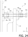
- Fig. 24 is an enlarged side view around the spring mechanism 156 of the supporting unit 150.
- the spring mechanism 156 includes a bolt 156a, a fixing plate 156b, a ring 156c, a nut 156d, an anti-vibration spring 156e, a cushion plate 156f, a washer 156g and nuts 156h.
- On a top portion of the arm 155 a through hole 155h extending in the X-axis direction is provided, and the bolt 156a is inserted in this through hole 155h.
- a tip of the bolt 156a is fixed to the movable block 158 via the fixing plate 156b. Also, a tip portion of the bolt 156a runs through the tubular ring 156c.
- the ring 156c is fixed by nipping between the nut 156d, screwed to the bolt 156a, and the fixing plate 156b. Also, a tip side of the bolt 156a is inserted in a hollow part of the tubular anti-vibration spring 156e. The anti-vibration spring 156e is retained by being nipped between the fixing plate 156b and the arm 155. Also, the ring 156c is fitted at an end side of the hollow part of the anti-vibration spring 156e.
- the anti-vibration spring 156e is a tubular member in which a compression coil spring made of steel is embedded in a viscoelastic body (damper) such as acrylic resins.
- a simple coil spring may be used in place of the anti-vibration spring 156e.
- a separate damper e.g., anti-vibration rubber or oil damper may be provided serially or parallel with the coil spring.
- the cushion plate 156f is, for example, formed of anti-vibration rubbers or resins such as polyurethane (i.e., rubbery elastic bodies and/or viscoelastic bodies).
- a preload (a compressing load in the X-axis direction) is applied to the anti-vibration spring 156e and the cushion plate 156f by the tightening of the bolt 156a, and the horizontal actuator 100A fixed to the movable block 158 is retained at a neutral position where restoring forces of the anti-vibration spring 156e and the cushion plate 156f balance. That is, the spring mechanism 156 functions as a neutral spring mechanism as well.
- a reaction force is transmitted to the movable blocks 158 of the supporting units 150, and is further transmitted to the fixing blocks 152 via the spring mechanisms 156 (anti-vibration springs 156e, cushion plates 156f) and the arms 155. Since the anti-vibration springs 156e and the cushion plates 156f attenuate vibrations with frequencies higher than their low resonance frequencies, transmission of vibration noises from the X-axis oscillating unit 100 to the device base 500 is suppressed by the supporting units 150.
- a reaction force acting on the supporting unit 150 in the X-axis positive direction is smaller than a reaction force in the X-axis negative direction. Therefore, a small and inexpensive cushion plate 156f is used as an elastic component that receives the reaction force in the X-axis positive direction. If the reaction force in the X-axis positive direction becomes large, an anti-vibration spring or a coil spring may be used in place of the cushion plate 156f. Also, if the reaction forces in both directions are small, a cushion plate may be used in place of the anti-vibration spring 156e.
- the fixing part 110 of the X-axis oscillating unit is supported softly and elastically with respect to the device base 500 in the driving direction (X-axis direction) by the supporting units 150 each including the linear guide 154 and the spring mechanism 156, and thus strong reaction forces (oscillating forces) in the X-axis direction that acts on the fixing part 110 during the driving of the X-axis oscillating unit 100 are not transmitted directly to the device base 500 but especially high frequency components of the reaction forces are attenuated by the spring mechanisms 156, and the reaction forces are then transmitted to the device base 500. Therefore, vibration noises that are transmitted from the X-axis oscillating unit 100 to the vibrating table 400 are reduced.
- the Y-axis oscillating unit 200 also includes the horizontal actuator 200A that has the same configuration as the horizontal actuator 100A.
- the fixing part 210 of the horizontal actuator 200A is also supported elastically on the device base 500 in the Y-axis direction by a pair of supporting units 250 ( Fig. 2 ). Since the supporting unit 250 has the same configuration as the supporting unit 150 of the X-axis oscillating unit 100, redundant detailed descriptions thereof are herein omitted.
- the rotational vibration of the vibrating table 400 is suppressed by the use of the low waving eight-streak linear guide as the biaxial sliders (YZ slider 160, ZX slider 260, XY slider 360) which greatly affect the oscillating performance, and, as a result, uniformity of the vibrating state (acceleration) on the vibrating table 400 is remarkably improved.
- oscillating performance specifications could only be prescribed at the reference point (the center of the top face of the vibrating table).
- due to this improvement in the uniformity it is made possible to prescribe the oscillating performance specifications within a wide area on the vibrating table.
- the center of gravity of the oscillated portion including the vibrating table and portions of the biaxial sliders
- the counter balancers or by creating a predetermined imbalance on the vibrating table in advance
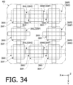
- Fig. 34 is a plan view illustrating a configuration of a variation 360A of the XY slider.
- the present variation is an XY slider in which the second orientation cross guide 364M2 arranged at the center is removed from the XY slider 360 of the above-described embodiment ( Fig. 12 ).
- the number of the first orientation cross guides 364P cross guides 364M1, 364L2, 364R2, 364M3 of which the X-axis linear guides 364X are attached to the vibrating table 400 and the number of the second orientation cross guides 364S (cross guides 364L1, 364R1, 364L3, 364R3) of which the Y-axis linear guides 364Y are attached to the vibrating table 400 are the same.
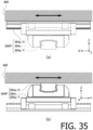
- Fig. 35(a) is a front view of the first orientation cross guide 364P, and (b) is a left side view thereof.
- the second orientation cross guide 364S of which the Y-axis linear guide 364Y (Y-axis rail 364a/Y) is attached to the vibrating table 400 contrary to the first orientation cross guide 364P described above, when the vibrating table 400 is oscillated in the X-axis direction, the Y-axis rail 364alY and the cross carriage 364c (solid lines) are oscillated in the X-axis direction along with the vibrating table 400, and only the X-axis rail 364a/X (broken lines) is not oscillated in the X-axis direction.
- Table 1 is a table in which relationships between the attaching orientations of the cross guide 364, the oscillating directions of the vibrating table, and oscillated parts of the cross guide 364 (components of the cross guide 364 which are oscillated along with the vibrating table 400) described above are organized.
- Table 1 cross guide oscillated parts of cross guide attaching orientation X-axis direction oscillation Y-axis direction oscillation first orientation X-axis rail X-axis rail cross guide Cross carriage second orientation Y-axis rail Y-axis rail cross guide cross carriage
- portions of the cross guide 364 which are oscillated along with the vibrating table 400 differ depending on the oscillating direction and the attaching orientation.
- the vibrating table 400 is oscillated in the X-axis direction
- the first orientation cross guide 364P only the X-axis rail 364a/X is oscillated in the X-axis direction
- the second orientation cross guide 364S the Y-axis rail 364alY and the cross carriage 364c are oscillated in the X-axis direction.
- the relationships between the oscillating direction and the number of components of the oscillated parts of the cross guide 364 (i.e., masses of the oscillated parts) for the first orientation cross guide 364P and for the second orientation cross guide 364S are opposite.
- the XY slider is configured only with the cross guide 364 of one of the attaching orientations (e.g., the first orientation cross guide 364P), the masses of the oscillated parts of the cross guide 364 change depending on whether the vibrating table 400 is oscillated in the X-axis direction or in the Y-axis direction. Due to this configuration, directionality occurs in the oscillating performance of the oscillating device 1.
- the sum of the masses of the oscillated parts of the cross guide 364 becomes constant regardless of whether the vibrating table 400 is oscillated in the X-axis direction or the Y-axis direction, and therefore the directionality in the oscillating performance can be reduced.
- the XY slider 360A of the present variation which is configured with four pairs of the first orientation cross guide 364P and the second orientation cross guide 364S has less directionality as compared to the XY slider 360 of the above embodiment in which the number of the second orientation cross guide 364S is greater than the number of the first orientation cross guide 364P by one, and thereby enables uniform oscillation.
- the oscillated portion is reduced in weight, thereby making it possible to oscillate with higher frequencies.
- substantially the entire surface of the side face of the vibrating table 400 on the X-axis negative direction side is substantially evenly supported by the slide coupling mechanism 160 (specifically, a plurality of the linear guideways in which the slide coupling mechanism 160 includes) and the movable part 120 of the X-axis oscillating unit 100.
- the slide coupling mechanism 160 specifically, a plurality of the linear guideways in which the slide coupling mechanism 160 includes
- the movable part 120 of the X-axis oscillating unit 100 By this configuration, it is configured such that the entire side face of the vibrating table 400 on the X-axis negative direction side can receive substantially even oscillating force from the X-axis oscillating unit 100.
- substantially the entire surface of the side face of the vibrating table 400 on the Y-axis negative direction side is substantially evenly supported by the slide coupling mechanism 260 and the movable part 220 of the Y-axis oscillating unit 200.
- it is configured such that the entire side face of the vibrating table 400 on the Y-axis negative direction side can receive substantially even oscillating force from the Y-axis oscillating unit 200.
- substantially the entire surface of the lower face of the vibrating table 400 is substantially evenly supported by the slide coupling mechanism 360 (specifically, a plurality of the linear guideways which the slide coupling mechanism 360 include) and the movable part 320 of the Z-axis oscillating unit 300.
- the slide coupling mechanism 360 specifically, a plurality of the linear guideways which the slide coupling mechanism 360 include
- the movable part 320 of the Z-axis oscillating unit 300 By this configuration, it is configured such that the entire lower face of the vibrating table 400 can receive substantially even oscillating force from the Z-axis oscillating unit 300.
- the entire oscillated portion (the oscillated object and portions of the oscillating device 1, such as the vibrating table 400, which are oscillated along with the oscillated object) is inside the vibrating table 400, the entire oscillated portion can be oscillated without applying moments of forces of high magnitudes to the entire oscillated portion. Due to this configuration, occurrence of unnecessary vibration components (vibration noises) caused by moments of forces applied to the entire oscillated portion are reduced, thereby making it possible to oscillate with higher accuracy.
- Fig. 36, Fig. 37 and Fig. 38 are a plan view, a front view and a left side view, respectively, of the vibrating table 400 in a state where an oscillated object T1 is attached.
- the vibrating table 400 is configured such that an oscillation of an oscillated object can be performed in a state where the oscillated object is accommodated inside the vibrating table 400.
- the vibrating table 400 includes a box part 400a having an opening on its top face, and a lid part 400b which closes the opening of the box part 400a.
- Fig. 36 shows a state where the lid part 400b is removed.
- the lid part 400b is detachably attached to the box part 400a by bolts (not shown) which fit female screws 421 provided on a top face of the box part 400a (more specifically, a frame part 420 which will be described later).
- the vibrating table 400 is configured such that its center of gravity is positioned substantially at the center of its outer shape.
- the box part 400a has a bottom plate 450, and a frame part (wall part) 420 which vertically protrudes upward from a peripheral edge of the bottom plate 450.
- the bottom plate 450 is formed in a shape in which four corners of a square are cut off.
- a plurality of intermediate plates 430, 440 parallel to respective wall surfaces of the frame part 420 (apart from the cut off portions) are provided in a lattice.
- the intermediate plates 430 extend in the Y-axis direction (right-left direction in Fig. 36 ), and the intermediate plates 440 extend in the X-axis direction (up-down direction in Fig. 36 ).
- the intermediate plates 430, 440 are joint to the bottom plate 450 and the frame part 420 at one end (or both ends) thereof.
- an accommodating space S which is a hollow part in which no intermediate plate (wall part) 430, 440 is formed. An oscillated object is accommodated in this accommodating space S.
- the oscillated object T1 is placed substantially at the center of the accommodating space S. Therefore, the center of gravity of the oscillated object T1 is positioned near the center of the vibrating table 400.
- the vibrating table 400 is configured to be able to oscillate an oscillated object having a rotating shaft (e.g., power transmission devices such as engines, motors and differential gears) in a state where the rotating shaft is rotated.
- the oscillated object T1 (and an oscillated object T2 which will be described later) is a generator for hybrid cars.
- an opening 422 for inserting a drive belt DB for transmitting power is formed on the left side face of the frame part 420.
- an opening 443 for inserting the drive belt DB is formed at a position opposing the opening 422.
- the drive belt DB is wound around a drive pulley (not shown) of an external driving device and a driven pulley FP attached to the oscillated object T1, and thus it is made possible to oscillate the oscillated object T1 while rotating the oscillated object T1 by applying a driving force to the oscillated object T1 inside the vibrating table 400 from outside during oscillation.
- one or more long objects of other types for connecting the oscillated object T1 with one or more external devices such as pipes for supplying hydraulic pressure or air pressure to the oscillated object T1, electrical power cables for supplying electrical power, and communication cables for communicably connecting an external information processing device and the oscillated object (or sensors or measuring devices attached to the oscillated object), can be inserted in the openings 422, 443.
- one or more openings for inserting these pipes and/or cables may be provided to the vibrating table 400 in addition to the openings 422, 443.
- the oscillated object is an engine
- the oscillated object and an external measuring device can be coupled by the drive belt DB, and power that the oscillated object generates can be measured while oscillating the oscillated object.
- a plurality of female screws 451 for fixing the oscillated object are provided.
- Fig. 39 is a left side view of the vibrating table 400 in a state where an oscillated object T2, having through holes for fixing at the bottom portion, is attached.
- the oscillated object T2 is fixed to the bottom plate 450 of the vibrating table 400 by screwing bolts B, inserted in the through holes for fixing of the oscillated object T2, in the female screws 451.
- the oscillated object T2 is attached substantially at the center of the accommodating space S, too. Therefore, the center of gravity of the oscillated object T2 is positioned near the center of the vibrating table 400. It is noted that, although, in Fig. 39 , the oscillated object T2 is directly fixed to the bottom plate 450 of the vibrating table 400, if the center of gravity of the oscillated object T2 is low, the oscillated object T2 may be fixed to the bottom plate 450 via a spacer or the like so as to position the center of gravity of the oscillated object T2 at the center of the vibrating table 400. Also, if the center of gravity of the oscillated object T2 is high, the oscillated object T2 may be, for example, fixed to the lid part 400b and attached to the vibrating table 400 upside down.
- an oscillated object and the vibrating table 400 are oscillated in a state where the oscillated object is accommodated inside the vibrating table 400. Since the center of gravity of the entire oscillated portion is surely positioned within the vibrating table 400 by accommodating the oscillated object inside the vibrating table 400, it becomes possible to surely reduce the occurrence of moments of forces on the entire oscillated portion.
- the vibrating table 400 of the above-described embodiment is configured to have a box shape with a lid
- the vibrating table 400 only needs to be configured such that, when an oscillated object is attached, the center of gravity of the entire oscillated portion is positioned within the vibrating table 400 (more precisely, within an area where a space formed by extending the movable part 320 (slide coupling mechanism 360) of the Z-axis oscillating unit 300 in the Z-axis direction and a space formed by extending the movable part 120 (slide coupling mechanism 160) of the X-axis oscillating unit 100 in the X-axis direction intersect).
- the vibrating table 400 only needs to be configured such that a projection of the center of gravity of the entire oscillated portion to the XY plane perpendicular to the Z-axis is included in a projection of the movable part 320 (slide coupling mechanism 360) of the Z-axis oscillating unit 300 to the XY plane, and a projection of the center of gravity of the entire oscillated portion to the YZ plane perpendicular to the X-axis is included in a projection of the movable part 120 (slide coupling mechanism 160) of the X-axis oscillating unit 100 to the YZ plane.
- the vibrating table 400 may have a configuration that only has a face of the frame part 420 to which the slide coupling mechanism 160 is attached and a bottom plate 450 to which the Z-axis oscillating unit 300 is attached.
- the present embodiment it is made possible to more surely approach the center of gravity the oscillated object toward the center of the vibrating table 400 by providing the accommodating space S (the intermediate plates 430a, 440a which separate the accommodating space S) at the center of the vibrating table 400.
- the present variation differs from the above embodiment only in the configurations of the biaxial sliders (slide coupling mechanisms).
- differences from the above embodiment will mainly be described, and descriptions of configurations that are common to those of the above embodiment are herein omitted.
- Fig. 40 is an enlarged perspective view (partially transparent view) around a vibrating table 2400 of an oscillating device 2000. It is noted that, in Fig. 40 , only an outline of the vibrating table 2400 is shown by two-dot lines. Also, illustrations of the counter balancers are omitted.
- each of biaxial sliders (YZ slider 2160, ZX slider 2260, XY slider 2360) of the present variation is configured with nine cross guides 2164, 2264, 2364 arranged at regular intervals in a lattice (three rows ⁇ three columns).
- the cross guides 2164, 2264, 2364 have the same configuration as the cross guide 364 of the XY slider 360.
- the XY slider 2360 has the same configuration as the XY slider 360 ( Fig. 12 ). That is, two arbitrary cross guides 2364 adjacent to each other in the X-axis direction or in the Y-axis direction are arranged mutually reversely in the up-down direction (in the Z-axis direction). That is, an X-axis rail 2364alX of one of the two arbitrary cross guides 2364 adjacent to each other in the X-axis direction or in the Y-axis direction is fixed to a tip face (top plate 2324b) of a movable part 2320, and the X-axis rail 2364alX of the other one is fixed to a lower face of the vibrating table 2400.
- directionalities in mass distribution and/or motion characteristic that each of the cross guides 2364 has are averaged, and thereby the oscillating performance with small directionality (or unevenness in directionalities) is obtained.
- the same arrangement configuration of the cross guides 364 (first orientation cross guides 364P, second orientation cross guides 364S) as the above embodiment is adopted to the arrangement of the cross guides 2164 for the YZ slider 2160 and the arrangement of the cross guides 2264 for the ZX slider 2260.
- a Y-axis rail 2164a/Y of one of two arbitrary cross guides 2164 adjacent to each other in the Y-axis direction or in the Z-axis direction is fixed to a tip face (top plate 2124b) of a movable part 2120, and the Y-axis rail 2164a/Y of the other one is fixed to a side face of the vibrating table 2400.
- an X-axis rail 2264a/X of one of two arbitrary cross guides 2264 adjacent to each other in the Z-axis direction or in the X-axis direction is fixed to a tip face (top plate 2224b) of a movable part 2220, and the X-axis rail 2264a/X of the other one is fixed to a side face of the vibrating table 2400.
- each face of the vibrating table 2400 is uniformly oscillated in three orthogonal directions by the same configuration as the above-described XY slider 2360. Therefore, uniform oscillation with less unevenness in vibrating states throughout the entire vibrating table 2400 becomes possible. Furthermore, since the vibrating table 2400 is oscillated in three orthogonal directions via the biaxial sliders (YZ slider 2160, ZX slider 2260, XY slider 2360) that have the same configuration, oscillation with lesser directionalities becomes possible.
- the YZ slider 2160 and the ZX slider 2260 may be configured with six cross guides 2164, 2264 arranged in two rows ⁇ three columns, obtained by removing three cross guides on the upper row or the lower row, among the nine cross guides 2164, 2264 arranged in three rows ⁇ three columns.
- the same number of the first orientation cross guides and the second orientation cross guides are alternately arranged in two orthogonal directions, directionalities in the oscillating performance are reduced and it becomes possible to further uniformly oscillate each part of the vibrating table 2400.
- Fig. 41 is an enlarged perspective view (partially transparent view) around a vibrating table 3400 of an oscillating device 3000. It is noted that, in Fig. 41 , only an outline of the vibrating table 3400 is shown by two-dot lines. Also, illustrations of the counter balancers are omitted.
- the arrangement configuration of the cross guides 364 (first orientation cross guides 364P, second orientation cross guides 364S) of the above-described variation 360A ( Fig. 34 ) of the XY slider is applied to each biaxial slider (YZ slider 3160, ZX slider 3260, XY slider 3360).
- the YZ slider 3160 and the ZX slider 3260 couple the vibrating table 3400 to respective horizontal actuators 3100A and 3200A by a larger number of cross guides 3164 and 3264 than the YZ slider 160 and the ZX slider 260 of the above embodiment, it is possible to further uniformly oscillate the vibrating table 3400. Furthermore, since, similarly to the variation 360A ( Fig. 34 ), the YZ slider 3160 and the ZX slider 3260 have configurations in which the same number of the first orientation cross guides and the second orientation cross guides are alternately arranged, directionalities in the oscillating performance are reduced and it becomes possible to further uniformly oscillate each part of the vibrating table 3400.
- the present variation differs from the above-described embodiment only in the configurations of the biaxial sliders (slide coupling mechanisms).
- differences from the above embodiment will mainly be described, and descriptions of configurations that are common to those of the above embodiment are herein omitted.
- Fig. 42 , Fig. 43 and Fig. 44 are an enlarged front view, an enlarged side view and an enlarged plan view around a vibrating table 4400 of an oscillating device 4000.
- the present variation differs from the configuration of the above embodiment in that, in cross guide parts 4164, 4264, 4364 of biaxial sliders (YZ slider 4160, ZX slider 4260, XY slider 4360), coupling plates 4164c, 4264c, 4364c are used to couple the linear guides to improve rigidities of the cross carriage parts.
- the YZ slider 4160 includes three Y-axis linear guides 4164/Y (Y-axis rails 4164a/Y and Y-axis carriages 4164b/Y), five Z-axis linear guides 4164/Z (Z-axis rails 4164a/Z and Z-axis carriages 4164b/Z), and a coupling plate 4164c that couples all the Y-axis linear guides 4164/Y and the Z-axis linear guides 4164/Z.
- the Y-axis carriage 4164b/Y and the Z-axis carriage 4164b/Z are eight-streak type carriages, but unlike the A-type carriage 364b/A, lowering of aspect ratios (shortening) and weight reductions by forming the notches C1, C2 are not made. It is noted that the A-type carriage 364b/A may be used as the Y-axis carriage 4164b/Y and the Z-axis carriage 4164b/Z. Also, the same carriage as the Y-axis carriage 4164b/Y (Z-axis carriage 4164b/Z) may be used in place of the A-type carriage 364b/A of other variations.
- the Y-axis linear guide 4164/Y is configured with one Y-axis rail 4164alY and two Y-axis carriages 4164b/Y.
- the Y-axis carriages 4164b/Y of three Y-axis linear guides 4164/Y are arranged in the Z-axis direction with substantially no gap therebetween, and are fixed to a tip face of a coupling arm 4162. Also, the Y-axis rails 4164alY are fixed to one face of the coupling plate 4164c. It is noted that the three Y-axis linear guides 4164/Y may be arranged in the Z-axis direction with intervals therebetween.
- the intervals between the Y-axis linear guides 4164/Y are made narrower than a width (a size in the Z-axis direction) of the Y-axis carriage 4164b/Y.
- the oscillating performance is improved by attaching the Y-axis carriage 4164b/Y, having large mass, not to the coupling plate 4164c which is oscillated in two axial directions (X-axis direction, Y-axis direction) but to the coupling arm 4162 which is oscillated only in the X-axis direction.
- the Y-axis rail 4164alY has uniform mass distribution in the Y-axis direction, occurrence of vibration due to weight distribution changes when oscillated in the Y-axis direction is low. Therefore, occurrence of vibration noises is reduced by attaching the Y-axis rails 4164a/Y to the coupling plate 4164c which is oscillated in the Y-axis direction.
- the Z-axis linear guide 4164/Z is configured with one Z-axis rail 4164a/Z and one Z-axis carriage 4164b/Z.
- the Z-axis carriages 4164b/Z of five Z-axis linear guides 4164/Z are arranged in the Y-axis direction with substantially no gap therebetween, and are fixed to the other face of the coupling plate 4164c. Also, the Z-axis rails 4164a/Z are fixed to a side face of the vibrating table 4400. It is noted that the five Z-axis linear guides 4164/Z may be arranged in the Y-axis direction with intervals therebetween.
- the intervals between the Z-axis linear guides 4164/Z are made narrower than a width (a size in the Y-axis direction) of the Z-axis carriage 4164b/Z.
- the three Y-axis linear guides 4164/Y are arranged in the Z-axis direction with no gap therebetween.
- the five Z-axis linear guides 4164/Z are arranged in the Y-axis direction with no gap therebetween.
- all the Y-axis rails 4164alY and the Z-axis carriages 4164b/Z are directly fixed to the coupling plate 4164c which has sufficiently high rigidity.
- the oscillating performance is improved by attaching the Z-axis carriage 4164b/Z, having large mass, not to the vibrating table 4400 which is oscillated in three axial directions (X-axis direction, Y-axis direction, Z-axis direction) but to the coupling plate 4164c which is oscillated only in two axial directions (X-axis direction, Y-axis direction).
- occurrence of vibration noises is reduced by attaching the Z-axis rails 4164a/Z to the vibrating table 4400 which is oscillated in the Z-axis direction.
- a plurality of the Y-axis rails 4164alY are spread substantially all over the surface, and the coupling plate 4164c is oscillated in the X-axis direction via a plurality of the Y-axis rails 4164a/Y that evenly cover one face of the coupling plate 4164c. Therefore, the entire coupling plate 4164c is uniformly oscillated in the X-axis direction. Furthermore, oscillating forces transmitted from the Y-axis linear guides 4164/Y are averaged by the coupling plate 4164c having a high rigidity, and are transmitted to the vibrating table 4400 via the Z-axis linear guides 4164/Z as a more uniform oscillating force.
- a plurality of the Z-axis rails 4164a/Z are spread substantially all over the surface, and the vibrating table 4400 is oscillated in the X-axis direction via a plurality of the Z-axis rails 4164a/Z that evenly cover this side face. Therefore, the entire vibrating table 4400 is uniformly oscillated in the X-axis direction, and uniform oscillation with less unevenness in accelerations and jerk inside the vibrating table 4400 becomes possible.
- the ZX slider 4260 has the same configuration as the above-described YZ slider 4160, detailed description thereof is omitted.
- the XY slider 4360 includes three X-axis linear guides 4364/X (X-axis rails 4364a/X and X-axis carriages 4364b/X), three Y-axis linear guides 4364/Y (Y-axis rails 4364a/Y and Y-axis carriages 4364b/Y), and a coupling plate 4364c that couples all the X-axis linear guides 4364/X and the Y-axis linear guides 4364/Y.
- the X-axis carriage 4364b/X and the Y-axis carriage 4364b/Y have the same configurations as the Y-axis carriage 4164b/Y and the Z-axis carriage 4164b/Z.
- the X-axis linear guide 4364/X is configured with one X-axis rail 4364alX and two X-axis carriages 4364b/X.
- the X-axis rails 4364alX of the three X-axis linear guides 4364/X are arranged in the Y-axis direction at regular intervals, and are fixed to a tip face of the movable part 320 of the Z-axis oscillating unit 300.
- the X-axis carriages 4364b/X are fixed to a lower face of the coupling plate 4364c.
- the Y-axis linear guide 4364/Y is also configured with one Y-axis rail 4364a/Y and two Y-axis carriages 4364b/Y.
- the Y-axis rails 4364alY of the three Y-axis linear guides 4364/Y are arranged in the X-axis direction at regular intervals, and are fixed to a top face of the coupling plate 4364c.
- the Y-axis carriages 4364a/Y are fixed to a lower face of the vibrating table 4400.
- the three X-axis linear guides 4364/X are arranged at intervals narrower than a width (a size in the Y-axis direction) of the X-axis carriage 4364b/X.
- the three Y-axis linear guides 4364/Y are arranged at intervals narrower than a width (a size in the X-axis direction) of the Y-axis carriage 4364b/Y.
- all the X-axis carriages 4364b/X and the Y-axis rails 4364alY are directly fixed to the coupling plate 4364c which has sufficiently high rigidity.
- a rigidity of the XY slider 4360 improves, and thereby makes the resonance frequency higher.
- the X-axis linear guides 4364/X and the Y-axis linear guides 4364/Y of the XY slider 4360 are arranged with intervals therebetween, similarly to the Y-axis linear guides 4164/Y and the Z-axis linear guides 4164/Z of the YZ slider 4160, the X-axis linear guides 4364/X and the Y-axis linear guides 4364/Y may be arranged with substantially no gap therebetween.
- the coupling plates 4164c, 4264c, 4364c are formed of stainless steel, if the oscillating performance of higher frequency is required, lighter structure materials such as aluminum alloys such as duralumin, magnesium alloys, carbon fiber composite materials or the like may be used to reduce inertia of the biaxial sliders.
- Fig. 45 is an external view of an oscillating device 5000.
- the present variation differs from the above embodiment in the configurations of the linear guides which are used in the biaxial sliders (slide coupling mechanisms), the movable part support mechanisms and the fixing part support mechanisms, and in the configurations of the biaxial sliders.
- differences from the above embodiment will mainly be described, and descriptions of configurations that are common to those of the above embodiment are herein omitted.
- Fig. 46 is a diagram showing a distal end of the Y-axis oscillating unit 5200 to which the ZX slider 5260 is attached.
- the ZX slider 5260 includes two Z-axis rails 5264a/Z, four Z-axis carriages 5264b/Z, four X-axis carriages 5264b/X, two X-axis rails 5264a/X and a coupling arm 5262.
- the coupling arm 5262 is a supporting member which is fixed to a top plate 5224b of an extension frame 5224.
- the two Z-axis rails 5264a/Z extending in the Z-axis direction are arranged in the X-axis direction with a predetermined interval therebetween, and are fixed to the coupling arm 5262.
- To each Z-axis rail 5264a/Z two Z-axis carriages 5264b/Z which slidably engage with the Z-axis rail 5264alZ are mounted.
- the two X-axis rails 5264a/X extending in the X-axis direction are arranged in the Z-axis direction with a predetermined interval therebetween, and are attached to a side face of the vibrating table 5400 ( Fig. 45 ) opposing the Y-axis oscillating unit 5200.
- To each X-axis rail 5264a/X two X-axis carriages 5264b/X which slidably engage with the X-axis rail 5264alX are mounted.
- Each Z-axis carriage 5264b/Z is integrally fixed to one of the X-axis carriages 5264b/X by bolts in a state where top faces of their carriages are superimposed with each other, thereby forming a cross carriage 5264.
- a pair of the Z-axis rails 5264a/Z and a pair of the X-axis rails 5264a/X are arranged in a curb shape, and are coupled by the cross carriages 5264 at positions where they intersect each other.
- a movable part 5220 of the Y-axis oscillating unit 5200 and the vibrating table 5400 are coupled slidably in both the X-axis direction and the Z-axis direction.
- the ZX slider 5260 includes a pair of the Z-axis rails 5264a/Z and a pair of the X-axis rails 5264alX each arranged in their width directions (regarding the Z-axis rails 5264a/Z, in the X-axis direction, and regarding the X-axis rails 5264alX, in the Z-axis direction) with intervals therebetween.
- rigidities of the ZX slider 5260 against moments of forces about longitudinal axes of respective rails improve, thereby making it possible to oscillate with higher frequencies.
- the interval for the X-axis rails 5264a/X is limited by a height of the vibrating table 5400. Therefore, one X-axis rail 5264a/X is attached at an upper end part of the side face of the vibrating table 5400, and the other X-axis rail 5264alX is attached to a lower end part of the side face of the vibrating table 5400. Also, the arrangement interval for the Z-axis rails 5264a/Z is limited by a diameter of the movable part 5220 (top plate 5224b) of the Y-axis oscillating unit 5200. Therefore, as shown in Fig.
- the interval for a pair of the Z-axis rail 5264a/Z is a maximum interval within a range in which each Z-axis rail 5264a/Z does not protrude outside a cylindrical surface formed by extending an outer peripheral surface of the movable part 5220 in the Y-axis direction.
- Fig. 48 is a longitudinal section view of the Z-axis rail 5264a/Z and the Z-axis carriage 5264b/Z of the ZX slider 5260 cut along a plane perpendicular to a longitudinal axis of the Z-axis rail 5264a/Z (i.e., XY plane).
- Fig. 49 is a figure viewing from the arrow direction of I-I line of Fig. 48 .
- the Z-axis linear guide 5264/Z is a linear guide in which rollers are used as the rolling bodies. By using rollers as the rolling bodies, high positional accuracies and rigidities can be obtained. It is noted that balls or linear guides can be used as the rolling bodies.
- a groove GR having a trapezoidal sectional shape and extending in the Z-axis direction is formed on each of both side faces in the Y-axis direction of the Z-axis rail 5264alZ shown in Fig. 48 . Also, as shown in Fig. 48 and Fig. 49 , to the Z-axis carriage 5264b/Z, the groove GR extending in the Z-axis direction is formed such that the groove GR surrounds the Z-axis rail 5264alZ. To each side wall of the groove GR, a protruding part PR extending along the groove GR of the Z-axis rail 5264alZ is formed.
- a pair of inclined faces To the protruding part PR, a pair of inclined faces, the inclined faces of the pair being parallel to respective inclined faces of the trapezoidal groove GR of the Z-axis rail 5264a/Z, is formed. Between the four inclined faces of a pair of the grooves GR and the opposing inclined faces of the protruding part PR, respective gaps are formed. In each of these four gaps, a plurality of rollers RE' (RE'h, RE'i, RE'j, RE'k) made of stainless steel and a retainer RT' made of resin and configured to rotatably retain and couple the rollers are accommodated. Each of the rollers RE' is retained by being nipped between the inclined face of the groove GR and the inclined face of the protruding part PR.
- no-load paths (roller escape passages) Q' (Q'a, Q'b, Q'c, Q'd), being parallel to four respective gaps described above, are formed.
- the no-load paths Q'a, Q'b, Q'c, Q'd communicate with respective gaps at both ends thereof. Thereby, circulating passages for allowing the rollers RE' (RE'h, RE'i, RE'j, RE'k) and the retainer RT' to circulate are formed.
- a plurality of rollers RE'h, RE'i, RE'j, RE'k circulate in respective circulating passages CP'a, CP'b, CP'c, CP'd along with the retainer RT'.
- the carriage can be supported by a plurality of rollers and a resistance in the Z-axis direction is maintained low by the rolling of the rollers RE' (RE'h, RE'i, RE'j, RE'k), and thus the Z-axis carriage 5264b/Z can be moved smoothly with respect to the Z-axis rail 5264alZ.
- the retainer RT' that couples a plurality of rollers has a plurality of spacer parts RT's positioned between the rollers RE'k and a pair of bands RT'b that couples a plurality of the spacer parts RT's. Both ends of each spacer part RT's are fixed to respective bands RT'b of the pair to form the ladder-like retainer RT'.
- Each roller RE'k is retained in a space surrounded by a pair of adjacent spacer parts RT's and the pair of bands RT'b.
- the YZ slider 5160 which couples the X-axis oscillating unit 5100 and the vibrating table 5400 also has the same configuration as the ZX slider 5260, and the vibrating table 5400 is coupled to the movable part of the X-axis oscillating unit 5100 slidably in the Y-axis direction and the Z-axis direction. Therefore, vibration components of the vibrating table 5400 in the Y-axis direction and the Z-axis direction will not be transmitted to the X-axis oscillating unit 5100 even if the vibrating table 5400 is vibrated in the Y-axis direction and the Z-axis direction by the Y-axis oscillating unit 5200 and the Z-axis oscillating unit 5300, respectively. Also, since the vibrating table 5400 hardly receives forces in the Y-axis direction and the Z-axis direction by the driving of the X-axis oscillating unit 5100, oscillation with less crosstalk becomes possible.
- Fig. 47 is a side view around the XY slider 5360.
- Fig. 50 is a diagram illustrating arrangements of rails of the XY slider 5360 to be attached to a top plate 5362 of a movable part 5320 of the Z-axis oscillating unit 5300.
- the XY slider 5360 includes four cross guides 5364.
- the cross guide 5364 (5364P, 5364S) includes one X-axis linear guide 5364/X (5364/XL, 5364/XH) and one Y-axis linear guide 5364/Y (5364/YH, 5364/YL).
- the X-axis linear guide 5364/X is configured with one X-axis rail 5364alX (5364a/XL, 5364a/XH) and one X-axis carriage 5364b/X (5364b/XL, 5364b/XH), and the Y-axis linear guide 5364/Y is configured with one Y-axis rail 5364a/Y (5364a/YH, 5364a/YL) and one Y-axis carriage 5364b/Y (5364b/YH, 5364b/YL).
- the X-axis carriage 5364b/X and the Y-axis carriage 5364b/Y are integrally fixed by bolts in a state where top faces of the carriages are superimposed with each other, thereby forming a cross carriage.
- This cross carriage has the same configuration as the cross carriage 5264 of the ZX slider 5260 described above.
- the cross guide 5364 includes the first orientation cross guide 5364P of which the X-axis linear guide 5364/X is attached to the vibrating table 5400, and the second orientation cross guide 5364S of which the Y-axis linear guide 5364/Y is attached to the vibrating table 5400.
- the X-axis rail 5364a/XL of the cross guide 5364P is attached to the top face of the top plate 5362, and the Y-axis rail 5364a/YH is attached to a lower face of the vibrating table 5400.
- each cross guide 5364 couples the movable part 5320 of the Z-axis oscillating unit 5300 and the vibrating table 5400 slidably in the X-axis direction and in the Y-axis direction.
- the X-axis linear guide 5364/X and the Y-axis linear guide 5364/Y attached to the top plate 5362 will be referred to as a lower X-axis linear guide 5364/XL (lower X-axis rail 5364a/XL, lower X-axis carriage 5364b/XL) and a lower Y-axis linear guide 5364/YL (lower Y-axis rail 5364a/YL, lower Y-axis carriage 5364b/YL), respectively.
- the X-axis linear guide 5364/X and the Y-axis linear guide 5364/Y attached to the vibrating table 5400 will be referred to as an upper X-axis linear guide 5364/XH (upper X-axis rail 5364a/XH, upper X-axis carriage 5364b/XH) and an upper Y-axis linear guide 5364/YH (upper Y-axis rail 5364a/YH, upper Y-axis carriage 5364b/YH), respectively.
- the four cross guides 5364 are attached at four corners of the top face of the substantially square shaped top plate 5362.
- the cross guides 5364P and 5364S are alternately arranged around a central axis Ax of the Z-axis oscillating unit 5300. That is, the arrangement of the cross guides 5364P and 5364S have four times rotation symmetry about the central axis Ax.
- the mass distribution of the XY slider 5360 about the central axis Ax is levelized. As a result, response characteristics of the XY slider 5360 to vibrations in the X-axis direction and the Y-axis direction are made more homogenous.
- the X-axis carriage 5364b/X and the Y-axis carriage 5364b/Y have the same structures apart from the types of the attachment holes (Four through holes are formed on the X-axis carriage 5364b/X, and four screw holes are formed on the Y-axis carriage 5364b/Y). Furthermore, the X-axis rail 5364alX and the Y-axis rail 5364a/Y are the same.
- Each linear guide (X-axis linear guide 5364/X, Y-axis linear guide 5364/Y) has different mass distributions in the X-axis direction and in the Y-axis direction.
- the mass distributions in the X-axis direction and in the Y-axis direction are levelized by coupling the two linear guides to form the cross guide 5364.
- the response characteristics of the XY slider 5360 to vibrations in the X-axis direction and the Y-axis direction are made more homogenous by this configuration as well.
- each oscillating unit (X-axis oscillating unit 5100, Y-axis oscillating unit 5200, Z-axis oscillating unit 5300) is attached to a device base 5500 via a pair of supporting units 5150, 5250, 5350 (fixing part support mechanism).
- the supporting unit 5150, 5250, 5350 is a cushioning device including elastic components (coil springs or air springs) that elastically support each oscillating unit 5100, 5200, 5300, and suppress transmission of vibration (especially the high frequency components) of each oscillating unit in the oscillating direction to the device base 5500.
- each oscillating unit 5100, 5200, 5300 By attaching each oscillating unit 5100, 5200, 5300 to the device base 5500 via the supporting unit 5150, 5250, 5350, transmission of vibrations between the oscillating units 5100, 5200, 5300 are suppressed, and triaxial oscillation with less crosstalk and higher accuracy becomes possible.
- a variation of the above embodiment differs from the above embodiment in the frame structures of the movable parts of respective electrodynamic actuators (horizontal actuators in the X-axis direction and the Y-axis direction, and a vertical actuator 6300A).
- respective electrodynamic actuators horizontal actuators in the X-axis direction and the Y-axis direction, and a vertical actuator 6300A.
- Fig. 51 is a front view of an electrodynamic triaxial oscillating device 6000 (only a Z-axis oscillating unit 6300, the vibrating table 400, the X-axis counter balancer 610, the Y-axis counter balancer 620 and the Z-axis counter balancer 630 are shown).
- the movable part 6320 of the vertical actuator 6300A includes a frame 6322.
- Fig. 52 and Fig. 53 are perspective views showing an outer appearance of the frame 6322.
- Fig. 52 is a diagram showing the frame 6322 viewed from the front side (vibrating table 400 side), and
- Fig. 53 a diagram showing the frame 6322 viewed from the back side.
- the frame 6322 as a whole is formed to have a substantially cylindrical shape of which the central axis extends in the driving direction (Z-axis direction).
- the frame 6322 is formed by the casting and cutting of aluminum alloys, but materials and processing methods for the frame 6322 are not limited to the above.
- the frame 6322 may be made of other metallic materials such as stainless steels, titanium alloys or magnesium alloys, or resin materials such as glass fiber reinforced plastics (GFRP) or carbon fiber reinforced plastics (CFRP).
- GFRP glass fiber reinforced plastics
- CFRP carbon fiber reinforced plastics
- the frame 6322 may be integrally formed by welding, adhesion, bonding, injection molding, three-dimensional modeling (3D printer) or the like.
- the frame 6322 includes a substantially tubular main column 6322a extending in the drive direction, eight plate-like ribs 6322b (6322b1, 6322b2) radially extending from an outer peripheral surface of the main column 6322a, a substantially circular front side peripheral edge part 6322c which couples distal ends of the eight ribs 6322b at the front side, a substantially circular back side peripheral edge part 6322d which couples distal ends of the eight ribs 6322b at the back side, and a tubular intermediate coupling part 6322e which couples intermediate portions in the radial direction (radiation direction) of the eight ribs 6322b at the front side. It is noted that, in the main column 6322a, the rod 326 (see Fig. 8 ) fits from below.
- the eight ribs 6322b are circularly coupled by the front side peripheral edge part 6322c, the back side peripheral edge part 6322d and the intermediate coupling part 6322e, it is made possible to satisfy both high rigidity and weight saving of the frame 6322. Also, by providing the intermediate coupling part 6322e, it is made possible to more evenly support a base plate 6362 (to support the base plate 6362 with a face).
- a plurality of tapped holes 6322ft for attaching the base plate 6362 are formed on a front side of the frame 6322 (specifically, the ribs 6322b, the front side peripheral edge part 6322c and the intermediate coupling part 6322e). Also, on a back side of the frame 6322 (specifically, the back side peripheral edge part 6322d), a plurality of screw holes 6322rt for attaching the drive coil 321 are formed.
- a row of screw holes 6322bt for attaching the Z-axis rails 344a of the movable part support mechanism 340 is formed on each of end faces (outer peripheral surfaces) of four ribs 6322b1 out of the eight ribs 6322b. Also, on end faces of the remaining four ribs 6322b2, fitting grooves 6322bg which fit with the coil attaching parts 322d are formed.
- the ribs 6322b1 and the ribs 6322b2 are alternately arranged in a circumferential direction.
- recessed parts 6322ca are formed near the ribs 6322b so as not to interfere with the Z-axis carriages 344b of the movable part support mechanism 340.
- a level difference 6322cb for positioning the Z-axis rail 344a in the horizontal direction is formed along the row of the holes 6322bt.
- An end face of the rib 6322b 1 on a front side on which the Z-axis rail 344a is to be attached is also offset toward the main column 6322a up to the same depth as the bottom of the recessed part 6322ca, thereby forming a rail attaching surface 6322br. Also, on the end face of the rib 6322b 1, a level difference 6322bs for positioning the Z-axis rail 344a in the vertical direction is formed at a boundary of the rail attaching surface 6322br.
- the movable part 320 of the above embodiment includes a split type (two-piece) frame in which an extension frame 324 is coupled to the main frame 322 with bolts.
- a split type frame structure By adopting the split type frame structure, it is made possible to additionally equip a standard electrodynamic actuator, having the main frame 322 only, with the movable part support mechanism 340.
- the split type frame structure requires a structure for coupling the two parts (the main frame 322 and the extension frame 324), and furthermore, the structure of the entire frame cannot be optimized (i.e., there is no choice but to design for the existing main frame 322), the split type frame structure causes the weight of the frame to increase, and thereby causes weight imbalance. Therefore, the split type frame structure is one of the causes that restrict the oscillating performance of the electrodynamic actuator. Furthermore, since the split type frame requires a process for coupling the two parts, more man-hour is necessary to assemble.
- the integrated (one-piece) frame 6322 is used in place of the main frame 322 and the expansion frame 324 of the above embodiment.
- the frame 6322 that is lighter, that has higher rigidity, that has better weight balance, and that can be assembled with less man-hour can be realized.
- the top plate 322b (corresponding to the base plate 6362 of the present variation) for attaching the XY slider 360 is formed integrally with the expansion frame 324, but in the present variation, the frame 6322 and the base plate 6362 are separate members. By this configuration, it becomes unnecessary to change the design of the frame 6322 in accordance with the design of the XY slider 360, and thus designing and production management of the frame 6322 becomes easier. Furthermore, as with the above embodiment, the frame 6322 and the base plate 6362 may be integrated.
- the present invention is applied to an electrodynamic oscillating device, but the present invention is not limited to this configuration and can be applied to oscillating devices which use other types of oscillating units (e.g., a linear motion oscillating unit in which a rotary electric motor or a hydraulic rotary motor and a rotation/linear motion conversion mechanism such as a feed screw mechanism are combined, a linear motor and the like) as well.
- a linear motion oscillating unit in which a rotary electric motor or a hydraulic rotary motor and a rotation/linear motion conversion mechanism such as a feed screw mechanism are combined, a linear motor and the like
- the present invention can be applied to an oscillating unit disclosed in International Publication No. 2009/011433 (Patent Document 1) in which a servo motor and a ball screw mechanism are used.
- each of the above described embodiments is an example in which the present invention is applied to an electrodynamic triaxial simultaneous oscillating device, but the present invention can of course be applied to uniaxial and biaxial oscillating devices as well.
- an air spring is used as a cushioning means for attenuating vibration of the supporting unit 350 (fixing part support mechanism), but configurations that use other types of springs that have vibration prevention effects (e.g., a coil spring made of steel) or elastic bodies (such as a vibration prevention rubber) are also possible.
- the number of linear guides (one, two, three, four, or five or more) for each axis and their arrangements in the slide coupling mechanism may be selected accordingly in accordance with a size of a vibrating table, a size and weight distribution of a specimen, test conditions (frequency and amplitude) and the like.
- the number of cross guides the XY slider 360 of the above embodiment and the YZ slider 2160, the ZX slider 2260 and the XY slider 2360 include is not limited to nine, but may be set to an arbitrary number of equal to or more than three in accordance with a size of a vibrating table, a weight of a specimen, test conditions and the like.
- the balls RE are used as rolling bodies of the linear guide, but rollers (skids) may be used as the rolling bodies.
- each of the above eight streaks of load paths are formed to the linear guide, but a plurality of load paths of five streaks, six streaks, seven streaks, or nine or more streaks may be provided. Also, in the linear guide of each of the above, a plurality of adjacently formed path pairs are provided, but the load paths need not be provided with the path pair as a fundamental unit. A plurality of load paths may be provided at uniform intervals, or may be provided at completely non-uniform intervals. It is noted that it is also possible to use the conventional four-streak type linear guide having four streaks of load paths.
- each oscillating direction is in the horizontal direction or the vertical direction, but the oscillating device may be arranged such that two or more axes of the three oscillating directions are in the non-vertical and non-horizontal directions.
- the cross guides are arranged in a square lattice in two orthogonal directions at regular intervals, but the cross guides may be arranged in a hexagonal lattice (equilateral triangle pattern).
- the XY slider can be made to have a configuration in which the first orientation cross guide is arranged at the center of gravity of a equilateral triangle shaped periodic structure (unit lattice) on the XY plane, and the second orientation cross guide is arranged at each apex of the equilateral triangle.
- the opening for putting the oscillated object in and out of the vibrating table 400 is formed on the top face of the box part 400a, but this opening may be provided on a side face of the box part.
- the female screws 421 and the through holes 432, 442 for attaching the oscillated object are provided on the vibrating table 400, but other types of attaching mechanisms (e.g., fixing bands, clamps, electromagnets or the like) for attaching the oscillated object may be provided on the vibrating table 400.
- the embodiment described above is an example in which the present invention is applied to an electrodynamic oscillating device, but the present invention is not limited to this configuration and can be applied to oscillating devices which use other types of oscillating units (e.g., a linear motion oscillating unit in which a rotary electric motor or a hydraulic rotary motor and a rotation/linear motion conversion mechanism such as a feed screw mechanism are combined, a linear motor, a hydraulic cylinder and the like) as well.
- oscillating units e.g., a linear motion oscillating unit in which a rotary electric motor or a hydraulic rotary motor and a rotation/linear motion conversion mechanism such as a feed screw mechanism are combined, a linear motor, a hydraulic cylinder and the like
- the oscillating device 1 of the embodiment described above is an example in which the present invention is applied to a biaxial oscillating device, but the present invention can be applied to uniaxial and triaxial oscillating devices as well.
- the present invention is applied to an electrodynamic oscillating device, but the present invention is not limited to this configuration and can be applied to oscillating devices which use other types of oscillating units (e.g., a linear motion oscillating unit in which a rotary electric motor or a hydraulic rotary motor and a rotation/linear motion conversion mechanism such as a feed screw mechanism are combined, a linear motor and the like) as well.
- a linear motion oscillating unit in which a rotary electric motor or a hydraulic rotary motor and a rotation/linear motion conversion mechanism such as a feed screw mechanism are combined, a linear motor and the like
- the present invention can be applied to an oscillating unit disclosed in International Publication No. 2009/011433 (Patent Document 1) in which a servo motor and a ball screw mechanism are used.
- the above described embodiment is an example in which the present invention is applied to an electrodynamic triaxial simultaneous oscillating device, but the present invention can of course be applied to uniaxial and biaxial oscillating devices as well.
- an air spring is used as a cushioning means for attenuating vibration of the supporting unit 350 (fixing part support mechanism), but configurations that use other types of springs that have vibration prevention effects (e.g., a coil spring made of steel) or elastic bodies (such as a vibration prevention rubber) are also possible.
- the number of linear guides (one, two, three, four, or five or more) for each axis and their arrangements in the slide coupling mechanism may be selected accordingly in accordance with a size of a vibrating table, a size and weight distribution of a specimen, test conditions (frequency and amplitude) and the like.
- the number of cross guides the XY slider 360 of the above embodiment and the YZ slider 2160, the ZX slider 2260 and the XY slider 2360 include is not limited to nine, but may be set to an arbitrary number of equal to or more than three in accordance with a size of a vibrating table, a weight of a specimen, test conditions and the like.
- the balls RE are used as rolling bodies of the linear guide, but rollers (skids) may be used as the rolling bodies.
- a triaxial oscillating device that oscillates a sample fixed to a vibrating table in three orthogonal axis directions is known.
- the vibrating table and an X-axis actuator for oscillating the vibrating table in the X-axis direction need to be coupled slidably in two directions orthogonal to the X-axis (Y-axis direction and Z-axis direction) with a biaxial slider.
- Japanese patent provisional publication No. 2012-237736 discloses an oscillating device that enabled triaxial oscillation at a high frequency range by adopting biaxial sliders which use roller bearing type linear guideways (Hereinafter simply referred to as "linear guide.”) that includes rolling bodies.
- slide coupling mechanisms for horizontal driving that couple the vibrating table to actuators which drive in horizontal directions (X-axis actuator, Y-axis actuator) are connected to the vibrating table via one Y-axis or X-axis rail.
- the oscillating device disclosed in Japanese patent provisional publication No. 2012-237736 is configured to receive moments of forces about the Y-axis (or X-axis) that act on the slide coupling mechanism for horizontal driving only with one thin Y-axis rail (or X-axis rail), a rigidity against the moments of forces about the Y-axis (or X-axis) is lower than a rigidity against moments of forces about the Z-axis. This was one of the causes that block improvement in an accuracy of the oscillating device (especially the improvement.in the oscillating performance at high frequency ranges).
- An aspect of the present invention is made in view of the above situation, and the object of the present invention is to improve the oscillating performance by improving the rigidity of the slide coupling mechanism.
Landscapes
- Physics & Mathematics (AREA)
- General Physics & Mathematics (AREA)
- Electromagnetism (AREA)
- Engineering & Computer Science (AREA)
- Mechanical Engineering (AREA)
- Apparatuses For Generation Of Mechanical Vibrations (AREA)
- Bearings For Parts Moving Linearly (AREA)
- Reciprocating, Oscillating Or Vibrating Motors (AREA)
- Machine Tool Units (AREA)
- Vibration Prevention Devices (AREA)
- Exposure And Positioning Against Photoresist Photosensitive Materials (AREA)
Claims (12)
- Schwingungsvorrichtung (1) umfassend:-einen Rütteltisch (400) für Schwingprüfungen;einen Aktuator (100, 200, 300) für das Oszillieren in eine erste Richtung;einen Schiebekupplungsmechanismus (160,260,360), der an einer Seite des Rütteltischs (400) zwischen dem Aktuator (100, 200, 300) und dem Rütteltisch (400) befestigt und für eine verschiebbare Bewegung im Verhältnis zu dem Aktuator (100, 200, 300) in eine zweite Richtung rechtwinklig zu der ersten Richtung konfiguriert ist;ein Gegengewicht (610, 620, 630), das ein Gewicht (612) umfasst, das an einer Seite des Rütteltischs (400) an einer gegenüberliegenden Seite des Schiebekupplungsmechanismus (160, 260, 360) befestigt ist, das Gegengewicht (610, 620, 630) ist so konfiguriert, dass es ein erstes Ungleichgewicht eines oszillierten Abschnitts ausgleicht, der mindestens den Rütteltisch (400) einschließt, das erste Ungleichgewicht wird verursacht durch das Befestigen des Schiebekupplungsmechanismus (160, 260, 360) an dem Rütteltisch (400);gekennzeichnet durch ein Dämpfungsteil (611), das zwischen dem Gewicht (612) und dem Rütteltisch (400) angebracht ist, wenn das Gewicht (612) am Rütteltisch (400) befestigt ist.
- Schwingungsvorrichtung (1) nach Anspruch 1, wobei das Gewicht (612, 632, 635, 638) in einer flachen Plattenform geformt ist.
- Schwingungsvorrichtung (1) nach Anspruch 1 oder 2, wobei das Dämpfungsteil (611, 631, 634, 637) in einer Scheibenform geformt ist.
- Schwingungsvorrichtung (1) nach einem der vorhergehenden Ansprüche, wobei das Dämpfungsteil (611, 611a) Elastomer umfasst.
- Schwingungsvorrichtung (1) nach einem der vorhergehenden Ansprüche, wobei das Dämpfungsteil (611) einen Abstandshalter (611a) umfasst.
- Schwingungsvorrichtung (1) nach einem der vorhergehenden Ansprüche, wobei das Gegengewicht (610, 620, 630) ein Gitter mit Durchgangsöffnungen (612c) und eine Vielzahl an Bolzen (613) umfasst, die für das Einsetzen in die Durchgangsöffnungen (612c) konfiguriert sind, um das Gewicht (612) an den entsprechenden Öffnungen (400h), die in dem Rütteltisch geformt sind, zu befestigen.
- Schwingungsvorrichtung (1) nach einem der Ansprüche 1 bis 5, wobei das Gegengewicht eine Vielzahl von Bolzen (613) umfasst, die konfiguriert sind, das Gewicht zu fixieren, und wobei die Vielzahl der Bolzen in Intervallen von gleich oder weniger als 100 mm angeordnet sind.
- Schwingungsvorrichtung (1) nach Anspruch 7, wobei die Vielzahl der Bolzen (613) in Intervallen von gleich oder weniger als 50 mm angeordnet sind.
- Schwingungsvorrichtung (1) nach einem der vorhergehenden Ansprüche, wobei das Gewicht (612) ein erstes Gewichtsteil (632) und ein zweites Gewichtsteil (635) umfasst; und wobei der Dämpfungsteil (611) einen ersten Dämpfungteilabschnitt (631) umfasst, der zwischen dem Rütteltisch (400) und dem ersten Gewichtsteil (632) bereitgestellt ist, und einen zweiten Dämpfungsteilabschnitt (634), der zwischen dem ersten Gewichtsteil (632) und dem zweiten Gewichtsteil (635) bereitgestellt ist.
- Schwingungsvorrichtung (1) nach Anspruch 9, wobei das Gewicht (612) ferner ein drittes Gewichtsteil (638) umfasst, und das Dämpfungsteil (611) ferner ein drittes Dämpfungsteil (637) umfasst, das zwischen dem zweiten Gewichtsteil (635) und dem dritten Gewichtsteil (638) bereitgestellt ist.
- Schwingungsvorrichtung nach Anspruch 10, wobei:Das erste Gewichtsteil mit einem ersten Bolzen an dem Rütteltisch befestigt ist,das zweite Gewichtsteil mit einem zweiten Bolzen an dem ersten Gewichtsteil befestigt ist, unddas dritte Gewichtsteil mit einem dritten Bolzen an dem zweiten Gewichtsteil befestigt ist.
- Schwingungsvorrichtung (1) nach einem der vorhergehenden Ansprüche, umfassend:-Einen zweiten Aktuator (100, 200, 300), der konfiguriert ist, den Rütteltisch (400) in einer zweiten Richtung zu oszillieren;einen dritten Aktuator (100, 200, 300), der konfiguriert ist, den Rütteltisch (400) in eine dritte Richtung rechtwinklig zu der ersten Richtung und der zweiten Richtung zu oszillieren;einen zweiten Schiebekupplungsmechanismus (160, 260, 360), der an einer Seite des Rütteltischs (400) zwischen dem zweiten Aktuator (100, 200, 300) und dem Rütteltisch (400) befestigt und für eine Bewegung im Verhältnis zu dem zweiten Aktuator (100, 200, 300) in die erste Richtung und die dritte Richtung konfiguriert ist;einen dritten Schiebekupplungsmechanismus (160, 260, 360), der an einer Seite des Rütteltischs (400) zwischen dem dritten Aktuator (100, 200, 300) und dem Rütteltisch (400) befestigt und für eine Bewegung im Verhältnis zu dem dritten Aktuator (100, 200, 300) in die erste Richtung und die zweite Richtung konfiguriert ist;ein zweites Gegengewicht (610, 620, 630), das ein Gewicht (612) umfasst, das an einer Seite des Rütteltischs (400) an einer gegenüberliegenden Seite des zweiten Schiebekupplungsmechanismus (160, 260, 360) befestigt ist, das zweite Gegengewicht (610, 620, 630) ist so konfiguriert, dass es ein zweites Ungleichgewicht eines oszillierten Abschnitts ausgleicht, der mindestens den Rütteltisch (400) einschließt, das zweite Ungleichgewicht wird verursacht durch das Befestigen des zweiten Schiebekupplungsmechanismus (160, 260, 360) an dem Rütteltisch (400);ein drittes Gegengewicht (610, 620, 630), das ein Gewicht (612) umfasst, das an einer Seite des Rütteltischs (400) an einer gegenüberliegenden Seite des dritten Schiebekupplungsmechanismus (160, 260, 360) befestigt ist, das dritte Gegengewicht (610, 620, 630) ist so konfiguriert, dass es ein drittes Ungleichgewicht eines oszillierten Abschnitts ausgleicht, der mindestens den Rütteltisch (400) einschließt, das dritte Ungleichgewicht wird verursacht durch das Befestigen des dritten Schiebekupplungsmechanismus (160, 260, 360) an dem Rütteltisch (400);wobei der Schiebekupplungsmechanismus (160, 260, 360) ferner konfiguriert ist, den Rütteltisch (400) mit dem Aktuator (100, 200, 300) für das Oszillieren in eine erste Richtung so zu koppeln, dass der Rütteltisch (400) im Verhältnis zu diesem Aktuator in die zweite und die dritte Richtung beweglich ist.
Priority Applications (2)
| Application Number | Priority Date | Filing Date | Title |
|---|---|---|---|
| EP21217141.7A EP4006518B1 (de) | 2016-01-15 | 2017-01-13 | Schwingvorrichtung und elektrodynamischer aktuator |
| EP23153789.5A EP4194833A1 (de) | 2016-01-15 | 2017-01-13 | Schwingungsapplikationsvorrichtung und elektrodynamischer aktuator |
Applications Claiming Priority (5)
| Application Number | Priority Date | Filing Date | Title |
|---|---|---|---|
| JP2016006691 | 2016-01-15 | ||
| JP2016006692 | 2016-01-15 | ||
| JP2016131170 | 2016-06-30 | ||
| JP2016205586A JP6771217B2 (ja) | 2016-10-19 | 2016-10-19 | 加振装置 |
| PCT/JP2017/000978 WO2017122770A1 (ja) | 2016-01-15 | 2017-01-13 | 加振装置及び動電型アクチュエータ |
Related Child Applications (4)
| Application Number | Title | Priority Date | Filing Date |
|---|---|---|---|
| EP23153789.5A Division-Into EP4194833A1 (de) | 2016-01-15 | 2017-01-13 | Schwingungsapplikationsvorrichtung und elektrodynamischer aktuator |
| EP23153789.5A Division EP4194833A1 (de) | 2016-01-15 | 2017-01-13 | Schwingungsapplikationsvorrichtung und elektrodynamischer aktuator |
| EP21217141.7A Division EP4006518B1 (de) | 2016-01-15 | 2017-01-13 | Schwingvorrichtung und elektrodynamischer aktuator |
| EP21217141.7A Division-Into EP4006518B1 (de) | 2016-01-15 | 2017-01-13 | Schwingvorrichtung und elektrodynamischer aktuator |
Publications (3)
| Publication Number | Publication Date |
|---|---|
| EP3404394A1 EP3404394A1 (de) | 2018-11-21 |
| EP3404394A4 EP3404394A4 (de) | 2019-12-25 |
| EP3404394B1 true EP3404394B1 (de) | 2023-11-22 |
Family
ID=59311914
Family Applications (3)
| Application Number | Title | Priority Date | Filing Date |
|---|---|---|---|
| EP17738522.6A Active EP3404394B1 (de) | 2016-01-15 | 2017-01-13 | Schwingungsanwendungsvorrichtung |
| EP21217141.7A Active EP4006518B1 (de) | 2016-01-15 | 2017-01-13 | Schwingvorrichtung und elektrodynamischer aktuator |
| EP23153789.5A Pending EP4194833A1 (de) | 2016-01-15 | 2017-01-13 | Schwingungsapplikationsvorrichtung und elektrodynamischer aktuator |
Family Applications After (2)
| Application Number | Title | Priority Date | Filing Date |
|---|---|---|---|
| EP21217141.7A Active EP4006518B1 (de) | 2016-01-15 | 2017-01-13 | Schwingvorrichtung und elektrodynamischer aktuator |
| EP23153789.5A Pending EP4194833A1 (de) | 2016-01-15 | 2017-01-13 | Schwingungsapplikationsvorrichtung und elektrodynamischer aktuator |
Country Status (8)
| Country | Link |
|---|---|
| US (4) | US10942085B2 (de) |
| EP (3) | EP3404394B1 (de) |
| KR (4) | KR20180104615A (de) |
| CN (5) | CN118294091A (de) |
| DE (3) | DE202017007626U1 (de) |
| ES (2) | ES2977338T3 (de) |
| TW (3) | TWI754361B (de) |
| WO (1) | WO2017122770A1 (de) |
Families Citing this family (19)
| Publication number | Priority date | Publication date | Assignee | Title |
|---|---|---|---|---|
| JP5913910B2 (ja) * | 2011-04-26 | 2016-04-27 | 国際計測器株式会社 | 直動アクチュエータ及び加振装置 |
| JP6564426B2 (ja) * | 2017-07-07 | 2019-08-21 | ファナック株式会社 | 部品供給装置及び機械学習装置 |
| CN109211506A (zh) * | 2018-10-30 | 2019-01-15 | 脉创测控装备科技(苏州)有限公司 | 试验设备、中心零位偏移控制装置及控制方法 |
| CN109269745B (zh) * | 2018-10-30 | 2021-01-19 | 湖南科技大学 | 基于托辊激振法的大型斗轮机悬臂低频振动测试方法 |
| CN111289198B (zh) * | 2020-02-17 | 2021-10-26 | 河南理工大学 | 一种改进型相似材料立体模拟实验支架 |
| CN111426443B (zh) * | 2020-03-18 | 2023-03-10 | 天津航天瑞莱科技有限公司 | 一种基于振动台的拦阻冲击试验方法 |
| CN111855123A (zh) * | 2020-06-01 | 2020-10-30 | 涡阳县沪涡多孔矸石砖有限公司 | 一种用于空心砖的抗震性检测系统 |
| DE102020208040B4 (de) * | 2020-06-29 | 2024-08-22 | Zf Friedrichshafen Ag | Verstellbare Prüflingsaufnahme für einen Antriebsstrangprüfstand und Antriebsstrangprüfstand |
| CN112098398A (zh) * | 2020-09-16 | 2020-12-18 | 沙锐 | 一种果蔬农药残留检测装置 |
| CN112730032B (zh) * | 2021-01-11 | 2025-02-14 | 大连理工大学 | 考虑真实复杂边界条件的结构多维加载试验系统 |
| CN112880953B (zh) * | 2021-01-21 | 2022-04-08 | 复旦大学 | 一种振动试验装置及振动测试的方法 |
| US11460370B2 (en) * | 2021-02-16 | 2022-10-04 | Raytheon Company | Multi-axis vibration test system with solid aluminum cube mounting fixture |
| CN114993590B (zh) * | 2021-02-24 | 2023-10-13 | 中国航发商用航空发动机有限责任公司 | 激振系统以及用于测试航空发动机转子的试验设备 |
| CN113743347B (zh) * | 2021-09-13 | 2024-08-09 | 郑州磨料磨具磨削研究所有限公司 | 一种考虑质量波动共振声混料机实时固有频率识别方法 |
| CN113720561B (zh) * | 2021-09-27 | 2024-08-30 | 苏州苏试试验集团股份有限公司 | 用于汽车发电机的振动测试平台 |
| CN115153939B (zh) * | 2022-08-05 | 2025-10-28 | 长沙微笑美齿智能科技有限公司 | 一种用于牙科种植体稳固度检测的感应线圈装置 |
| CN115406610B (zh) * | 2022-09-01 | 2025-07-01 | 中国矿业大学 | 一种电动振动台三轴向自动倒台装置 |
| CN118670653A (zh) * | 2023-03-14 | 2024-09-20 | 英业达科技有限公司 | 测试治具 |
| CN117387886B (zh) * | 2023-09-07 | 2026-04-03 | 华南理工大学 | 多层准零刚度减震结构振动测控装置及方法 |
Family Cites Families (74)
| Publication number | Priority date | Publication date | Assignee | Title |
|---|---|---|---|---|
| US3369393A (en) | 1964-11-27 | 1968-02-20 | Sanders Associates Inc | Multiple element fabricated test fixture |
| US3916677A (en) | 1973-08-06 | 1975-11-04 | Koehring Co | Portable load supporting platform |
| JPS5539307Y2 (de) * | 1976-07-20 | 1980-09-13 | ||
| JPS5382372A (en) | 1976-12-28 | 1978-07-20 | Sakura Denki Kk | Vibration tester in lateral vibrating type |
| JPS6050309B2 (ja) | 1978-06-19 | 1985-11-07 | 日本電気株式会社 | 半導体装置の定加速度試験用治具 |
| JPS58146943U (ja) | 1982-03-29 | 1983-10-03 | 三菱重工業株式会社 | 振動試験における加振治具 |
| US4603587A (en) * | 1985-02-19 | 1986-08-05 | Kimball Industries, Inc. | High productivity vibration test fixture suited for testing printed circuit boards |
| JPS6372380A (ja) | 1986-09-17 | 1988-04-02 | 株式会社日立製作所 | 動電型加振機構 |
| US4848160A (en) | 1987-10-21 | 1989-07-18 | M/Rad Corporation | Multi-axis test fixture system |
| JPH0531541Y2 (de) * | 1988-03-24 | 1993-08-13 | ||
| US4948123A (en) * | 1989-12-18 | 1990-08-14 | Schook Michael N | Quick release dumbell and barbell exercise equipment |
| JPH04332839A (ja) * | 1991-05-09 | 1992-11-19 | Fujitsu Ltd | 振動試験装置 |
| US5253531A (en) * | 1992-04-10 | 1993-10-19 | Walker Dana A | System and method for monitoring torsional vibrations and operating parameters of rotating shafts |
| JP2860745B2 (ja) * | 1993-03-22 | 1999-02-24 | アイエムブイ株式会社 | 振動試験装置 |
| US5397206A (en) * | 1994-03-15 | 1995-03-14 | Chrysler Corporation | Vibration isolating fastener |
| JPH0835907A (ja) | 1994-07-25 | 1996-02-06 | Fujitsu Ten Ltd | 恒温槽付き加振機 |
| US5804732A (en) * | 1995-12-21 | 1998-09-08 | Venturedyne, Ltd. | Vibrator-driven table apparatus |
| US5969256A (en) * | 1996-12-26 | 1999-10-19 | Hobbs; Gregg K. | Modular vibration system |
| JP2000077815A (ja) * | 1998-08-31 | 2000-03-14 | Mitsubishi Electric Corp | 給電構造 |
| US6105433A (en) * | 1999-03-02 | 2000-08-22 | Qualmark Corporation | Shaker table assembly for a reliability test chamber utilizing different types of vibrator assemblies |
| JP2002236074A (ja) * | 2001-02-09 | 2002-08-23 | Mitsubishi Heavy Ind Ltd | 共振型振動装置 |
| JP4571333B2 (ja) | 2001-04-19 | 2010-10-27 | 株式会社ミツトヨ | 振動発生機における転倒モーメント測定方法 |
| JP2003149077A (ja) | 2001-11-15 | 2003-05-21 | Akashi Corp | 加振機 |
| JP2004219083A (ja) | 2003-01-09 | 2004-08-05 | Akashi Corp | 振動発生機 |
| JP2004219196A (ja) | 2003-01-14 | 2004-08-05 | Akashi Corp | 動電式振動発生機 |
| JP2004222440A (ja) | 2003-01-16 | 2004-08-05 | Akashi Corp | 電磁石及び振動試験機 |
| JP2004219307A (ja) | 2003-01-16 | 2004-08-05 | Akashi Corp | 振動試験機 |
| JP2004286544A (ja) | 2003-03-20 | 2004-10-14 | Akashi Corp | 振動試験機 |
| JP2005062097A (ja) | 2003-08-19 | 2005-03-10 | Akashi Corp | 振動試験装置 |
| JP4223376B2 (ja) | 2003-11-19 | 2009-02-12 | 株式会社ミツトヨ | 振動発生機 |
| JP4244832B2 (ja) | 2004-03-17 | 2009-03-25 | トヨタ自動車株式会社 | エンジンブロックの振動伝達特性解析装置 |
| US7806697B2 (en) * | 2005-08-15 | 2010-10-05 | Cae Inc. | Method and apparatus for damping vibrations in a motion simulation platform |
| JP2007248399A (ja) | 2006-03-17 | 2007-09-27 | Sharp Corp | 振動試験装置 |
| US7610819B2 (en) * | 2006-08-01 | 2009-11-03 | Avl North America Inc. | Transmission headstock for test stands |
| JP4325689B2 (ja) * | 2007-02-28 | 2009-09-02 | 株式会社日立製作所 | 回転電機 |
| JPWO2009011282A1 (ja) | 2007-07-18 | 2010-09-24 | Thk株式会社 | 運動案内装置及びねじ装置 |
| KR101132191B1 (ko) | 2007-07-19 | 2012-04-06 | 고쿠사이 게이소쿠키 가부시키가이샤 | 진동시험장치 |
| JP5123598B2 (ja) | 2007-07-31 | 2013-01-23 | Thk株式会社 | 転動装置 |
| US7784349B2 (en) * | 2007-08-27 | 2010-08-31 | Venturedyne, Ltd. | Vibrator table frame |
| WO2009130953A1 (ja) | 2008-04-25 | 2009-10-29 | 国際計測器株式会社 | 動電型振動試験装置 |
| JP2010025790A (ja) | 2008-07-22 | 2010-02-04 | Fuji Electric Systems Co Ltd | 評価実験用記録装置 |
| JP5311549B2 (ja) | 2008-08-08 | 2013-10-09 | 株式会社日立製作所 | 振動試験装置 |
| CN101430238B (zh) * | 2008-12-04 | 2010-08-18 | 上海大学 | 用于检测滤毒罐耐振动冲击性的测试仪 |
| JP4633838B2 (ja) | 2008-12-09 | 2011-02-16 | 国際計測器株式会社 | 振動試験装置 |
| CN101750201B (zh) * | 2008-12-09 | 2014-10-08 | 国际计测器株式会社 | 振动试验装置 |
| JP4589997B2 (ja) | 2008-12-09 | 2010-12-01 | 国際計測器株式会社 | 振動試験装置 |
| US8025586B2 (en) * | 2008-12-19 | 2011-09-27 | ANEEGING GOLF Ltd. | Golf club |
| JP2010175532A (ja) * | 2008-12-29 | 2010-08-12 | Kokusai Keisokki Kk | 振動試験装置 |
| JP5373462B2 (ja) | 2009-04-15 | 2013-12-18 | Thk株式会社 | 運動案内装置 |
| US8100017B1 (en) * | 2009-06-15 | 2012-01-24 | Western Digital Technologies, Inc. | Vibration test apparatus with an actuator coupled to a reaction mass movable along a linear axis |
| JP2011112487A (ja) * | 2009-11-26 | 2011-06-09 | Mitsubishi Heavy Ind Ltd | 加振装置 |
| KR101637175B1 (ko) | 2010-02-08 | 2016-07-21 | 삼성전자 주식회사 | 평판표시패널용 지그장치 및 이를 이용한 내구성 테스트 방법 |
| CN102410914A (zh) | 2010-09-17 | 2012-04-11 | 英业达股份有限公司 | 治具与振动设备 |
| JP6130892B2 (ja) | 2011-04-26 | 2017-05-17 | 国際計測器株式会社 | 動電型アクチュエータ及び動電型加振装置 |
| JP5913910B2 (ja) | 2011-04-26 | 2016-04-27 | 国際計測器株式会社 | 直動アクチュエータ及び加振装置 |
| US8479597B2 (en) * | 2011-04-29 | 2013-07-09 | Michael B. Pickel | Thermal test chamber |
| KR101968460B1 (ko) * | 2011-07-08 | 2019-04-11 | 신포니아 테크놀로지 가부시끼가이샤 | 진동 장치, 물품 반송 장치 및 물품 분별 장치 |
| JP5910085B2 (ja) | 2012-01-04 | 2016-04-27 | 株式会社Ihi | 加振装置 |
| CN102865987B (zh) * | 2012-09-17 | 2015-01-07 | 苏州苏试试验仪器股份有限公司 | 平面静压式传振解耦装置及三轴向振动复合试验台 |
| CN102865986B (zh) * | 2012-09-17 | 2015-08-19 | 苏州苏试试验仪器股份有限公司 | 多轴振动复合试验工作台面的平衡结构 |
| CN202793723U (zh) * | 2012-09-17 | 2013-03-13 | 苏州苏试试验仪器股份有限公司 | 多轴振动复合试验工作台面的平衡结构 |
| EP2728332B1 (de) * | 2012-10-31 | 2018-09-26 | Siemens Aktiengesellschaft | Testanlage |
| JP5695248B2 (ja) | 2013-04-10 | 2015-04-01 | Thk株式会社 | 運動案内装置 |
| JP5758475B2 (ja) | 2013-11-28 | 2015-08-05 | Imv株式会社 | 動電型振動発生機 |
| JP6030543B2 (ja) | 2013-12-26 | 2016-11-24 | エスペック株式会社 | 環境試験装置 |
| JP2015141156A (ja) | 2014-01-30 | 2015-08-03 | トヨタ自動車株式会社 | 試験体の方向転換装置及び方向転換方法 |
| JP6351488B2 (ja) | 2014-04-10 | 2018-07-04 | Thk株式会社 | 転動装置 |
| US9726718B2 (en) | 2014-05-30 | 2017-08-08 | Skyworks Solutions, Inc. | Modular test fixture |
| DE202015010027U1 (de) | 2014-07-30 | 2023-10-05 | Kokusai Keisokuki Kabushiki Kaisha | Oszilliervorrichtung zur Verbindung eines Rütteltisches mit einer Z-Achsen-Oszilliereinheit |
| US9410574B2 (en) | 2014-10-21 | 2016-08-09 | Hiwin Technologies Corp. | Linear ball bearing guideway |
| CN104819816B (zh) * | 2015-05-13 | 2017-11-03 | 中国飞机强度研究所 | 一种动载荷加载系统及飞机垂尾试验系统及方法 |
| CN104880291B (zh) * | 2015-05-29 | 2018-09-25 | 四川鸿舰重型机械制造有限责任公司 | 用于基础松动造成轴承座轴向振动大的诊断方法 |
| CN204953279U (zh) * | 2015-08-31 | 2016-01-13 | 国际计测器株式会社 | 激振装置 |
| CN204957624U (zh) * | 2015-08-31 | 2016-01-13 | 国际计测器株式会社 | 电动型致动器和激振装置 |
-
2017
- 2017-01-13 EP EP17738522.6A patent/EP3404394B1/de active Active
- 2017-01-13 DE DE202017007626.8U patent/DE202017007626U1/de active Active
- 2017-01-13 CN CN202410536606.0A patent/CN118294091A/zh active Pending
- 2017-01-13 CN CN201780006934.8A patent/CN108474716A/zh active Pending
- 2017-01-13 WO PCT/JP2017/000978 patent/WO2017122770A1/ja not_active Ceased
- 2017-01-13 KR KR1020187020124A patent/KR20180104615A/ko not_active Ceased
- 2017-01-13 ES ES17738522T patent/ES2977338T3/es active Active
- 2017-01-13 CN CN202410536363.0A patent/CN118225360A/zh active Pending
- 2017-01-13 CN CN202410536471.8A patent/CN118225361A/zh active Pending
- 2017-01-13 ES ES21217141T patent/ES3008665T3/es active Active
- 2017-01-13 KR KR1020257031448A patent/KR20250145127A/ko active Pending
- 2017-01-13 DE DE202017007630.6U patent/DE202017007630U1/de active Active
- 2017-01-13 KR KR1020247035645A patent/KR20240160229A/ko not_active Ceased
- 2017-01-13 DE DE202017007638.1U patent/DE202017007638U1/de active Active
- 2017-01-13 EP EP21217141.7A patent/EP4006518B1/de active Active
- 2017-01-13 EP EP23153789.5A patent/EP4194833A1/de active Pending
- 2017-01-13 CN CN202011083578.XA patent/CN112161772A/zh active Pending
- 2017-01-13 KR KR1020217040246A patent/KR102723693B1/ko active Active
- 2017-01-16 TW TW109129125A patent/TWI754361B/zh active
- 2017-01-16 TW TW106101368A patent/TWI736573B/zh active
- 2017-01-16 TW TW110125601A patent/TWI786720B/zh active
-
2018
- 2018-07-13 US US16/034,777 patent/US10942085B2/en active Active
-
2021
- 2021-01-27 US US17/159,447 patent/US11898944B2/en active Active
- 2021-12-29 US US17/565,070 patent/US20220120634A1/en not_active Abandoned
-
2024
- 2024-01-18 US US18/416,111 patent/US12442715B2/en active Active
Also Published As
Similar Documents
| Publication | Publication Date | Title |
|---|---|---|
| EP3404394B1 (de) | Schwingungsanwendungsvorrichtung | |
| JP7634902B2 (ja) | 加振装置 | |
| US10436670B2 (en) | Oscillating device, electrodynamic actuator, cross guideway, linear guideway and vibrating table | |
| CN105743275A (zh) | 电动线性致动器和电动激振装置 | |
| JP6820006B2 (ja) | 加振装置、振動テーブル及び加振方法 | |
| JP6771217B2 (ja) | 加振装置 | |
| JP6855050B2 (ja) | 動電型アクチュエータ及び加振装置 |
Legal Events
| Date | Code | Title | Description |
|---|---|---|---|
| STAA | Information on the status of an ep patent application or granted ep patent |
Free format text: STATUS: THE INTERNATIONAL PUBLICATION HAS BEEN MADE |
|
| PUAI | Public reference made under article 153(3) epc to a published international application that has entered the european phase |
Free format text: ORIGINAL CODE: 0009012 |
|
| STAA | Information on the status of an ep patent application or granted ep patent |
Free format text: STATUS: REQUEST FOR EXAMINATION WAS MADE |
|
| 17P | Request for examination filed |
Effective date: 20180809 |
|
| AK | Designated contracting states |
Kind code of ref document: A1 Designated state(s): AL AT BE BG CH CY CZ DE DK EE ES FI FR GB GR HR HU IE IS IT LI LT LU LV MC MK MT NL NO PL PT RO RS SE SI SK SM TR |
|
| AX | Request for extension of the european patent |
Extension state: BA ME |
|
| DAV | Request for validation of the european patent (deleted) | ||
| DAX | Request for extension of the european patent (deleted) | ||
| RIC1 | Information provided on ipc code assigned before grant |
Ipc: G01M 7/02 20060101ALI20190812BHEP Ipc: G01M 7/06 20060101AFI20190812BHEP |
|
| REG | Reference to a national code |
Ref legal event code: R079 Ipc: G01M0007060000 Ref country code: DE Ref legal event code: R079 Ref document number: 602017076732 Country of ref document: DE Free format text: PREVIOUS MAIN CLASS: G01M0007020000 Ipc: G01M0007060000 |
|
| A4 | Supplementary search report drawn up and despatched |
Effective date: 20191122 |
|
| RIC1 | Information provided on ipc code assigned before grant |
Ipc: G01M 7/06 20060101AFI20191118BHEP Ipc: G01M 7/02 20060101ALI20191118BHEP |
|
| STAA | Information on the status of an ep patent application or granted ep patent |
Free format text: STATUS: EXAMINATION IS IN PROGRESS |
|
| 17Q | First examination report despatched |
Effective date: 20211018 |
|
| GRAP | Despatch of communication of intention to grant a patent |
Free format text: ORIGINAL CODE: EPIDOSNIGR1 |
|
| STAA | Information on the status of an ep patent application or granted ep patent |
Free format text: STATUS: GRANT OF PATENT IS INTENDED |
|
| RIC1 | Information provided on ipc code assigned before grant |
Ipc: B06B 1/04 20060101ALI20230614BHEP Ipc: G01M 7/02 20060101ALI20230614BHEP Ipc: G01M 7/06 20060101AFI20230614BHEP |
|
| INTG | Intention to grant announced |
Effective date: 20230707 |
|
| GRAS | Grant fee paid |
Free format text: ORIGINAL CODE: EPIDOSNIGR3 |
|
| GRAA | (expected) grant |
Free format text: ORIGINAL CODE: 0009210 |
|
| STAA | Information on the status of an ep patent application or granted ep patent |
Free format text: STATUS: THE PATENT HAS BEEN GRANTED |
|
| AK | Designated contracting states |
Kind code of ref document: B1 Designated state(s): AL AT BE BG CH CY CZ DE DK EE ES FI FR GB GR HR HU IE IS IT LI LT LU LV MC MK MT NL NO PL PT RO RS SE SI SK SM TR |
|
| REG | Reference to a national code |
Ref country code: GB Ref legal event code: FG4D |
|
| REG | Reference to a national code |
Ref country code: CH Ref legal event code: EP Ref country code: DE Ref legal event code: R096 Ref document number: 602017076732 Country of ref document: DE |
|
| P01 | Opt-out of the competence of the unified patent court (upc) registered |
Effective date: 20231030 |
|
| REG | Reference to a national code |
Ref country code: IE Ref legal event code: FG4D |
|
| REG | Reference to a national code |
Ref country code: NL Ref legal event code: FP |
|
| REG | Reference to a national code |
Ref country code: LT Ref legal event code: MG9D |
|
| PG25 | Lapsed in a contracting state [announced via postgrant information from national office to epo] |
Ref country code: GR Free format text: LAPSE BECAUSE OF FAILURE TO SUBMIT A TRANSLATION OF THE DESCRIPTION OR TO PAY THE FEE WITHIN THE PRESCRIBED TIME-LIMIT Effective date: 20240223 |
|
| PG25 | Lapsed in a contracting state [announced via postgrant information from national office to epo] |
Ref country code: IS Free format text: LAPSE BECAUSE OF FAILURE TO SUBMIT A TRANSLATION OF THE DESCRIPTION OR TO PAY THE FEE WITHIN THE PRESCRIBED TIME-LIMIT Effective date: 20240322 |
|
| PG25 | Lapsed in a contracting state [announced via postgrant information from national office to epo] |
Ref country code: LT Free format text: LAPSE BECAUSE OF FAILURE TO SUBMIT A TRANSLATION OF THE DESCRIPTION OR TO PAY THE FEE WITHIN THE PRESCRIBED TIME-LIMIT Effective date: 20231122 |
|
| REG | Reference to a national code |
Ref country code: AT Ref legal event code: MK05 Ref document number: 1634261 Country of ref document: AT Kind code of ref document: T Effective date: 20231122 |
|
| PG25 | Lapsed in a contracting state [announced via postgrant information from national office to epo] |
Ref country code: AT Free format text: LAPSE BECAUSE OF FAILURE TO SUBMIT A TRANSLATION OF THE DESCRIPTION OR TO PAY THE FEE WITHIN THE PRESCRIBED TIME-LIMIT Effective date: 20231122 |
|
| PG25 | Lapsed in a contracting state [announced via postgrant information from national office to epo] |
Ref country code: LT Free format text: LAPSE BECAUSE OF FAILURE TO SUBMIT A TRANSLATION OF THE DESCRIPTION OR TO PAY THE FEE WITHIN THE PRESCRIBED TIME-LIMIT Effective date: 20231122 Ref country code: IS Free format text: LAPSE BECAUSE OF FAILURE TO SUBMIT A TRANSLATION OF THE DESCRIPTION OR TO PAY THE FEE WITHIN THE PRESCRIBED TIME-LIMIT Effective date: 20240322 Ref country code: GR Free format text: LAPSE BECAUSE OF FAILURE TO SUBMIT A TRANSLATION OF THE DESCRIPTION OR TO PAY THE FEE WITHIN THE PRESCRIBED TIME-LIMIT Effective date: 20240223 Ref country code: BG Free format text: LAPSE BECAUSE OF FAILURE TO SUBMIT A TRANSLATION OF THE DESCRIPTION OR TO PAY THE FEE WITHIN THE PRESCRIBED TIME-LIMIT Effective date: 20240222 Ref country code: AT Free format text: LAPSE BECAUSE OF FAILURE TO SUBMIT A TRANSLATION OF THE DESCRIPTION OR TO PAY THE FEE WITHIN THE PRESCRIBED TIME-LIMIT Effective date: 20231122 Ref country code: PT Free format text: LAPSE BECAUSE OF FAILURE TO SUBMIT A TRANSLATION OF THE DESCRIPTION OR TO PAY THE FEE WITHIN THE PRESCRIBED TIME-LIMIT Effective date: 20240322 |
|
| PG25 | Lapsed in a contracting state [announced via postgrant information from national office to epo] |
Ref country code: SE Free format text: LAPSE BECAUSE OF FAILURE TO SUBMIT A TRANSLATION OF THE DESCRIPTION OR TO PAY THE FEE WITHIN THE PRESCRIBED TIME-LIMIT Effective date: 20231122 Ref country code: RS Free format text: LAPSE BECAUSE OF FAILURE TO SUBMIT A TRANSLATION OF THE DESCRIPTION OR TO PAY THE FEE WITHIN THE PRESCRIBED TIME-LIMIT Effective date: 20231122 Ref country code: PL Free format text: LAPSE BECAUSE OF FAILURE TO SUBMIT A TRANSLATION OF THE DESCRIPTION OR TO PAY THE FEE WITHIN THE PRESCRIBED TIME-LIMIT Effective date: 20231122 Ref country code: NO Free format text: LAPSE BECAUSE OF FAILURE TO SUBMIT A TRANSLATION OF THE DESCRIPTION OR TO PAY THE FEE WITHIN THE PRESCRIBED TIME-LIMIT Effective date: 20240222 Ref country code: LV Free format text: LAPSE BECAUSE OF FAILURE TO SUBMIT A TRANSLATION OF THE DESCRIPTION OR TO PAY THE FEE WITHIN THE PRESCRIBED TIME-LIMIT Effective date: 20231122 Ref country code: HR Free format text: LAPSE BECAUSE OF FAILURE TO SUBMIT A TRANSLATION OF THE DESCRIPTION OR TO PAY THE FEE WITHIN THE PRESCRIBED TIME-LIMIT Effective date: 20231122 |
|
| PG25 | Lapsed in a contracting state [announced via postgrant information from national office to epo] |
Ref country code: DK Free format text: LAPSE BECAUSE OF FAILURE TO SUBMIT A TRANSLATION OF THE DESCRIPTION OR TO PAY THE FEE WITHIN THE PRESCRIBED TIME-LIMIT Effective date: 20231122 |
|
| PG25 | Lapsed in a contracting state [announced via postgrant information from national office to epo] |
Ref country code: CZ Free format text: LAPSE BECAUSE OF FAILURE TO SUBMIT A TRANSLATION OF THE DESCRIPTION OR TO PAY THE FEE WITHIN THE PRESCRIBED TIME-LIMIT Effective date: 20231122 |
|
| PG25 | Lapsed in a contracting state [announced via postgrant information from national office to epo] |
Ref country code: SK Free format text: LAPSE BECAUSE OF FAILURE TO SUBMIT A TRANSLATION OF THE DESCRIPTION OR TO PAY THE FEE WITHIN THE PRESCRIBED TIME-LIMIT Effective date: 20231122 |
|
| PG25 | Lapsed in a contracting state [announced via postgrant information from national office to epo] |
Ref country code: SM Free format text: LAPSE BECAUSE OF FAILURE TO SUBMIT A TRANSLATION OF THE DESCRIPTION OR TO PAY THE FEE WITHIN THE PRESCRIBED TIME-LIMIT Effective date: 20231122 Ref country code: SK Free format text: LAPSE BECAUSE OF FAILURE TO SUBMIT A TRANSLATION OF THE DESCRIPTION OR TO PAY THE FEE WITHIN THE PRESCRIBED TIME-LIMIT Effective date: 20231122 Ref country code: RO Free format text: LAPSE BECAUSE OF FAILURE TO SUBMIT A TRANSLATION OF THE DESCRIPTION OR TO PAY THE FEE WITHIN THE PRESCRIBED TIME-LIMIT Effective date: 20231122 Ref country code: EE Free format text: LAPSE BECAUSE OF FAILURE TO SUBMIT A TRANSLATION OF THE DESCRIPTION OR TO PAY THE FEE WITHIN THE PRESCRIBED TIME-LIMIT Effective date: 20231122 Ref country code: DK Free format text: LAPSE BECAUSE OF FAILURE TO SUBMIT A TRANSLATION OF THE DESCRIPTION OR TO PAY THE FEE WITHIN THE PRESCRIBED TIME-LIMIT Effective date: 20231122 Ref country code: CZ Free format text: LAPSE BECAUSE OF FAILURE TO SUBMIT A TRANSLATION OF THE DESCRIPTION OR TO PAY THE FEE WITHIN THE PRESCRIBED TIME-LIMIT Effective date: 20231122 |
|
| REG | Reference to a national code |
Ref country code: ES Ref legal event code: FG2A Ref document number: 2977338 Country of ref document: ES Kind code of ref document: T3 Effective date: 20240822 |
|
| REG | Reference to a national code |
Ref country code: DE Ref legal event code: R097 Ref document number: 602017076732 Country of ref document: DE |
|
| PG25 | Lapsed in a contracting state [announced via postgrant information from national office to epo] |
Ref country code: MC Free format text: LAPSE BECAUSE OF FAILURE TO SUBMIT A TRANSLATION OF THE DESCRIPTION OR TO PAY THE FEE WITHIN THE PRESCRIBED TIME-LIMIT Effective date: 20231122 |
|
| PG25 | Lapsed in a contracting state [announced via postgrant information from national office to epo] |
Ref country code: MC Free format text: LAPSE BECAUSE OF FAILURE TO SUBMIT A TRANSLATION OF THE DESCRIPTION OR TO PAY THE FEE WITHIN THE PRESCRIBED TIME-LIMIT Effective date: 20231122 |
|
| REG | Reference to a national code |
Ref country code: CH Ref legal event code: PL |
|
| PG25 | Lapsed in a contracting state [announced via postgrant information from national office to epo] |
Ref country code: LU Free format text: LAPSE BECAUSE OF NON-PAYMENT OF DUE FEES Effective date: 20240113 |
|
| PLBE | No opposition filed within time limit |
Free format text: ORIGINAL CODE: 0009261 |
|
| STAA | Information on the status of an ep patent application or granted ep patent |
Free format text: STATUS: NO OPPOSITION FILED WITHIN TIME LIMIT |
|
| PG25 | Lapsed in a contracting state [announced via postgrant information from national office to epo] |
Ref country code: LU Free format text: LAPSE BECAUSE OF NON-PAYMENT OF DUE FEES Effective date: 20240113 |
|
| PG25 | Lapsed in a contracting state [announced via postgrant information from national office to epo] |
Ref country code: BE Free format text: LAPSE BECAUSE OF NON-PAYMENT OF DUE FEES Effective date: 20240131 |
|
| PG25 | Lapsed in a contracting state [announced via postgrant information from national office to epo] |
Ref country code: CH Free format text: LAPSE BECAUSE OF NON-PAYMENT OF DUE FEES Effective date: 20240131 |
|
| PG25 | Lapsed in a contracting state [announced via postgrant information from national office to epo] |
Ref country code: SI Free format text: LAPSE BECAUSE OF FAILURE TO SUBMIT A TRANSLATION OF THE DESCRIPTION OR TO PAY THE FEE WITHIN THE PRESCRIBED TIME-LIMIT Effective date: 20231122 |
|
| 26N | No opposition filed |
Effective date: 20240823 |
|
| PG25 | Lapsed in a contracting state [announced via postgrant information from national office to epo] |
Ref country code: SI Free format text: LAPSE BECAUSE OF FAILURE TO SUBMIT A TRANSLATION OF THE DESCRIPTION OR TO PAY THE FEE WITHIN THE PRESCRIBED TIME-LIMIT Effective date: 20231122 Ref country code: CH Free format text: LAPSE BECAUSE OF NON-PAYMENT OF DUE FEES Effective date: 20240131 Ref country code: BE Free format text: LAPSE BECAUSE OF NON-PAYMENT OF DUE FEES Effective date: 20240131 |
|
| REG | Reference to a national code |
Ref country code: BE Ref legal event code: MM Effective date: 20240131 |
|
| PG25 | Lapsed in a contracting state [announced via postgrant information from national office to epo] |
Ref country code: IE Free format text: LAPSE BECAUSE OF NON-PAYMENT OF DUE FEES Effective date: 20240113 |
|
| PG25 | Lapsed in a contracting state [announced via postgrant information from national office to epo] |
Ref country code: IE Free format text: LAPSE BECAUSE OF NON-PAYMENT OF DUE FEES Effective date: 20240113 |
|
| PG25 | Lapsed in a contracting state [announced via postgrant information from national office to epo] |
Ref country code: CY Free format text: LAPSE BECAUSE OF FAILURE TO SUBMIT A TRANSLATION OF THE DESCRIPTION OR TO PAY THE FEE WITHIN THE PRESCRIBED TIME-LIMIT; INVALID AB INITIO Effective date: 20170113 |
|
| PG25 | Lapsed in a contracting state [announced via postgrant information from national office to epo] |
Ref country code: HU Free format text: LAPSE BECAUSE OF FAILURE TO SUBMIT A TRANSLATION OF THE DESCRIPTION OR TO PAY THE FEE WITHIN THE PRESCRIBED TIME-LIMIT; INVALID AB INITIO Effective date: 20170113 |
|
| PG25 | Lapsed in a contracting state [announced via postgrant information from national office to epo] |
Ref country code: FI Free format text: LAPSE BECAUSE OF FAILURE TO SUBMIT A TRANSLATION OF THE DESCRIPTION OR TO PAY THE FEE WITHIN THE PRESCRIBED TIME-LIMIT Effective date: 20231122 |
|
| PG25 | Lapsed in a contracting state [announced via postgrant information from national office to epo] |
Ref country code: TR Free format text: LAPSE BECAUSE OF FAILURE TO SUBMIT A TRANSLATION OF THE DESCRIPTION OR TO PAY THE FEE WITHIN THE PRESCRIBED TIME-LIMIT Effective date: 20231122 |
|
| PGFP | Annual fee paid to national office [announced via postgrant information from national office to epo] |
Ref country code: NL Payment date: 20260122 Year of fee payment: 10 |
|
| PGFP | Annual fee paid to national office [announced via postgrant information from national office to epo] |
Ref country code: GB Payment date: 20260112 Year of fee payment: 10 |
|
| PGFP | Annual fee paid to national office [announced via postgrant information from national office to epo] |
Ref country code: ES Payment date: 20260210 Year of fee payment: 10 |
|
| PGFP | Annual fee paid to national office [announced via postgrant information from national office to epo] |
Ref country code: DE Payment date: 20260127 Year of fee payment: 10 |
|
| PGFP | Annual fee paid to national office [announced via postgrant information from national office to epo] |
Ref country code: IT Payment date: 20260123 Year of fee payment: 10 |
|
| PGFP | Annual fee paid to national office [announced via postgrant information from national office to epo] |
Ref country code: FR Payment date: 20260126 Year of fee payment: 10 |