EP3409391A2 - Machine-outil pour une machine d'extrusion destiné à la fabrication en continu d'un profilé d'une matière à extruder déformable ainsi que procédé de changement de la roue de friction - Google Patents
Machine-outil pour une machine d'extrusion destiné à la fabrication en continu d'un profilé d'une matière à extruder déformable ainsi que procédé de changement de la roue de friction Download PDFInfo
- Publication number
- EP3409391A2 EP3409391A2 EP18179253.2A EP18179253A EP3409391A2 EP 3409391 A2 EP3409391 A2 EP 3409391A2 EP 18179253 A EP18179253 A EP 18179253A EP 3409391 A2 EP3409391 A2 EP 3409391A2
- Authority
- EP
- European Patent Office
- Prior art keywords
- receiving
- friction wheel
- tool
- drive shaft
- die
- Prior art date
- Legal status (The legal status is an assumption and is not a legal conclusion. Google has not performed a legal analysis and makes no representation as to the accuracy of the status listed.)
- Granted
Links
Images



Classifications
-
- B—PERFORMING OPERATIONS; TRANSPORTING
- B21—MECHANICAL METAL-WORKING WITHOUT ESSENTIALLY REMOVING MATERIAL; PUNCHING METAL
- B21C—MANUFACTURE OF METAL SHEETS, WIRE, RODS, TUBES, PROFILES OR LIKE SEMI-MANUFACTURED PRODUCTS OTHERWISE THAN BY ROLLING; AUXILIARY OPERATIONS USED IN CONNECTION WITH METAL-WORKING WITHOUT ESSENTIALLY REMOVING MATERIAL
- B21C23/00—Extruding metal; Impact extrusion
- B21C23/005—Continuous extrusion starting from solid state material
-
- B—PERFORMING OPERATIONS; TRANSPORTING
- B21—MECHANICAL METAL-WORKING WITHOUT ESSENTIALLY REMOVING MATERIAL; PUNCHING METAL
- B21C—MANUFACTURE OF METAL SHEETS, WIRE, RODS, TUBES, PROFILES OR LIKE SEMI-MANUFACTURED PRODUCTS OTHERWISE THAN BY ROLLING; AUXILIARY OPERATIONS USED IN CONNECTION WITH METAL-WORKING WITHOUT ESSENTIALLY REMOVING MATERIAL
- B21C23/00—Extruding metal; Impact extrusion
- B21C23/21—Presses specially adapted for extruding metal
- B21C23/212—Details
-
- B—PERFORMING OPERATIONS; TRANSPORTING
- B21—MECHANICAL METAL-WORKING WITHOUT ESSENTIALLY REMOVING MATERIAL; PUNCHING METAL
- B21C—MANUFACTURE OF METAL SHEETS, WIRE, RODS, TUBES, PROFILES OR LIKE SEMI-MANUFACTURED PRODUCTS OTHERWISE THAN BY ROLLING; AUXILIARY OPERATIONS USED IN CONNECTION WITH METAL-WORKING WITHOUT ESSENTIALLY REMOVING MATERIAL
- B21C25/00—Profiling tools for metal extruding
- B21C25/02—Dies
Definitions
- the invention relates to a tool unit for an extrusion molding machine for the continuous production of profiles from a deformable extruded material and a method for changing a friction wheel of the extrusion molding machine, as described in the claims 1 and 8.
- a device for continuous extrusion which includes a rotatable wheel with a circumferential groove.
- the extrusion tool composed of a plurality of tool elements is inserted in a stepped receiving opening.
- the extrusion tool In the open position of the tool holder, the extrusion tool can be seen in the bottom-side direction of this.
- the stripping element is held screwed in a screwed and jammed position on the tool elements forming the extrusion tool.
- the WO 2012/119196 A1 describes an extrusion press for the continuous production of profiles from a deformable extruded material.
- the extrusion press comprises a base frame and at least one friction wheel which can be rotated about a drive axis and which is provided with at least one circumferential groove.
- the friction wheel is in drive connection with a drive unit.
- the extrusion press also comprises a pressure roller, a tool holding device with a tool unit supported therein with a die, and a locking device.
- the tool holding device is mounted on a pivot axis arranged on the base frame and can be pivoted about the pivot axis between a working position and a release position.
- the tool holding device is seen in the direction of passage of the profile to be produced, downstream of the friction wheel.
- the present invention has for its object to provide a tool unit which forms a related assembly in which a simple exchange or change of tool components is possible and still a flawless support and positioning in operation is possible.
- a method for changing the friction wheel of the extrusion press which allows easy accessibility to the friction wheel and associated with a short downtime can be achieved.
- the advantage resulting from the features of claim 1 lies in the fact that the individual tool parts or tool components can be received and supported on it by the formation of a separate receiving cage for forming the tool unit therein. This makes it possible to prepare the individual components of the tool unit required for the respective profile to be produced and to arrange them accordingly in the receiving cage.
- the receiving cage With its receiving cage parts and supporting the die and the other in the exit direction successively arranged tool components on the receiving space supporting support surface can already be done so a corresponding load transfer on the receiving cage back to the tool holding device of the extrusion machine. This can be dispensed with, for example, additional glands or other connection means. It is only necessary to pay attention to a corresponding alignment of the individual tool components to each other.
- the receiving groove for receiving the scraper this can be inserted with appropriate guidance accuracy of the receiving groove without additional fasteners and be supported load-bearing in the receiving groove. This creates the possibility of being able to carry out a simple exchange or change with appropriate wear, without the need for additional and tedious manipulation activities.
- an axial guidance is achieved for the die as well, whereby a simple modular system of the tool unit can be created. With a uniform outer dimension so different profile geometries can be formed in the die. A change can be made easily, in which only the two receiving cage parts are to be separated from each other and a corresponding die and optionally further spacer elements is to be inserted into the receiving space.
- the receiving cage has at its outlet end a first bearing surface, which is aligned with respect to the profile axis in a perpendicular thereto extending plane and at its located in the insertion position lower side another with respect to the first bearing surface to angled, in particular at right angles,
- a uniform receiving cage can be created in which a variety of tool components can be added.
- the possibility is created according to the profile geometry to be produced always to assemble a unit which is to be used in its entirety in the extrusion press. But so that the component cost and thus additional costs can be reduced because the individual recording cages always different, to smaller dimensions having component components are used.
- the pressure element of the printing unit is at least partially accommodated in a pressure chamber and acted upon by a pressure medium in the pressure chamber, with which the pressure element is pressed against the second side of the tool holder or in the case of an adjustment of the actuating element and the thereby performed pivoting movement of the tool holding device about the pivot axis, the pressure element is adjustable by a change in volume of the pressure medium in the pressure chamber in its relative position with respect to the pressure unit.
- the drive unit of the friction wheel on both sides of the friction wheel arranged and rotatably mounted on the base frame first and second drive shaft parts, of which at least one of the drive shaft parts is adjustable in the axial direction with respect to the base frame of a contact position on the friction wheel in a spaced apart from the friction wheel change position for the friction, so a drive unit can be created in which the friction wheel between the drive shaft parts in an axial clamping position between these drive shaft parts can be clamped.
- at least one of the drive shaft parts is mounted relative to the base frame axially adjustable out, so easier accessibility for the removal of the friction wheel from the entire drive unit can be created.
- the embodiment is advantageous in which at at least one of the drive shaft parts, preferably on both the drive shaft parts, a driver ring is provided on the side facing the friction wheel, and at least one of the friction wheel facing annular end face of at least one of the driver rings, the first coupling elements are arranged or formed.
- a uniform drive unit can be created, wherein friction wheels of different widths can be received via the at least one driver ring.
- the friction wheel can be connected with the interposition of or Mit recruitingringe with the drive shaft parts in a corresponding manner.
- the position of the friction wheel can also be adapted or adjusted to the tool unit accommodated in the tool holding device and its position.
- the friction wheel at its two mutually spaced in the direction of the drive axis end faces each have a plurality of circumferentially offset from one another arranged second coupling elements, as characterized even more even transmission of the drive torque can be done on the friction wheel.
- an embodiment proves to be advantageous in which the support shaft is provided on an axis end region facing the first drive shaft part with an external thread, which can be screwed to a arranged in the first receiving opening of the first drive shaft part internal thread, as characterized a positive connection between the support shaft and the first drive shaft part can be created.
- This type of positive connection is to be solved by a simple rotational movement and, in turn, in turn, this positive connection easy to produce for acting on it axial tensile and compressive forces.
- the support shaft is slidably guided in the second receiving opening formed in the second drive shaft part, since a better axial guidance of the support shaft on the base frame can thus be achieved. Furthermore, but also an independent adjustment of the support axis relative to the take second drive shaft part and still sufficient support and guiding effect for the support axis can be achieved.
- an embodiment is also advantageous in which the support shaft can be adjusted at least as far as possible from an insert position passing through the friction wheel and screwed to the internal thread of the first drive shaft part in the axial direction in the direction away from the first drive shaft part such that an axis end facing the first drive shaft part is outside the friction wheel is arranged.
- This allows a simple distancing of at least one drive shaft part from the friction wheel arranged therebetween.
- the form-fitting coupling elements can be disengaged so that the removal of the friction wheel is facilitated.
- even a tool-free change of the friction wheel is possible.
- the second drive shaft part is adjustable together with the support shaft received therein in the axial direction of the contact wheel resting on the contact position in the spaced from the friction wheel change position for the friction wheel, as this facilitates the removal of the friction wheel between the two drive shaft parts can be.
- the accessibility is further improved and the handling easier for the assembly staff.
- the possibility is also created to be able to remove the friction wheel from the drive unit with external lifting means.
- the resulting from the feature combination of this claim advantages are that so a simple change possibility of the friction wheel from the entire drive unit can be created in which sufficient space is available to carry out this assembly and switching activity.
- the drive unit is divided into arranged on both sides of the friction wheel drive shaft parts, they can be dissociated from each other for the assembly activity.
- the arranged within the drive shaft parts common support shaft is used in operation to create a more rigid drive unit.
- the support shaft still serves to build up sufficient clamping forces between the two drive shaft parts, so as to be able to set and hold the friction wheel in an axial clamping position therebetween.
- the fact that the positive connection between the support shaft and the first drive shaft part can be solved, as well as the friction wheel passing through position of the support shaft can be changed, whereby an unimpeded removal of the friction wheel can be done from the drive unit.
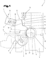
- This extrusion molding machine 1 shown here represents a special form of extrusion presses 1, which enables continuous production.
- extruded material 3 for example, a continuously supplied wire with a diameter between 5 and 30 mm of the extrusion press 1 is fed and heated there via a driven friction wheel 4 depending on umzuformendem material up to 500 ° C and above. The then doughy material is pressed by a die disposed immediately after the friction wheel 4, wherein in this section of the molding process takes place.
- This continuous process is used primarily for profiles 2 of small and medium dimensions. In this case, a wide variety of materials, such as aluminum, copper, non-ferrous metals or their alloys can be reshaped.
- the friction wheel 4 is rotatable about a drive shaft 8 in a known manner and is further in drive connection with an only schematically indicated drive unit 9. Furthermore, the at least one provided friction wheel 4 also has at least one circumferential groove. Furthermore, at least one pressure roller 10 can be assigned to the one or more friction wheels 4 with which the extruded material 3 entering and / or forming the extrusion press 1 is pressed against the friction wheel or wheels 4 in the radial direction.
- the gap width of the gap between the friction wheel 4 and the tool unit 12 on the one hand depends on the temperature of the system parts and on the other hand wear phenomena of the tool unit 12, a fairly accurate and above all readjustable adjustment of the gap width of the gap is independent in the present invention Aspect.
- the maintenance and adjustment of the gap width can represent an independent task of the invention and in a corresponding manner independent of the others described here system parts and process steps represent a stand-alone solution.
- a separate actuator 14 is arranged.
- the adjusting device 14 has a relative to the base frame 5 to adjustably trained actuator 15.
- the adjusting element 15 in turn has a footprint 16 facing the end area 13 of the tool holding device 6 and a guide surface 17 facing away from the tool holding device 6.
- the footprint 16 and the guide surface 17 are aligned wedge-shaped to each other.
- the guide surface 17 is supported on an unspecified, in particular designed as a sliding surface portion of the base frame 5 from.
- the actuator 15 is further connected to an unspecified actuating mechanism and is relative to the base frame 5 in the direction of a schematically registered double arrow adjustable.
- the guide surface 17 extends approximately perpendicularly, wherein the inclined extending thereto aligned footprint 16 extends from top left to bottom right, as can be seen from the side view of the extrusion molding machine 1.
- the locking device 11 described above furthermore has at least one pressure unit 19 with at least one pressure element 20.
- the pressure element 20 when the tool holding device 6 is in the working position, the pressure element 20 is likewise arranged on the end area 13 distanced from the pivot axis 7, but is in contact with the tool holding device 6 on a second side facing away from the friction wheel 4. Furthermore, by means of Pressure unit 19, the support surface 18 of the tool holding device 6 is pressed against the footprint 16 of the actuating element 15.
- the adjusting element 15 is further supported with its guide surface 17 on the base frame 5, at a relative displacement of the adjusting element 15 by means of the adjusting device 14, the tool holding device 6 about its pivot axis 7 due to the wedge-shaped, in particular acute-angled, mutually aligned footprint 16 and guide surface 17 done. Since the tool holding device 6 in the broadest sense corresponds to a lever or a lever arrangement, the gap formed between the tool unit 12 and the friction wheel 4 can thus also be changed in its gap width as a result of the adjustment of the adjusting element.
- the pressure element 20 of the pressure unit 19 is received at least in regions in a pressure chamber 21 and thereby acted on by a pressure medium indicated by dashes and located in the pressure chamber 21.
- the pressure medium may be liquid or gaseous, wherein, especially at high pressures, a nearly incompressible liquid, such as hydraulic oil, has proven to be favorable.
- the pressure element 20 may be formed, for example, as a double-acting piston of a cylinder-piston assembly, which then the pressure element 20 is pressed against the second side of the tool holder device 6 with a corresponding application.
- a receiving chamber 24 is formed or arranged in the tool holding device 6.
- the outlines of the receiving chamber 24 are shown only simplified, in which the tool unit 12 is added.
- the receiving chamber 24 at least two angled, in particular at right angles to each other aligned first and second positioning surfaces 25, 26, on which the tool unit 12 is supported.
- the first positioning surface 25 is arranged on the side of the tool unit 12 facing away from the friction wheel 4.
- the receiving chamber 24 is formed open in the direction of the friction wheel 4.
- the first positioning surface 25 may be aligned approximately vertically and in the vertical direction with respect to the direction of passage of the profile 2.
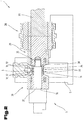
- Fig. 2 to 4 an optionally independent embodiment of the drive unit 9 of the extrusion molding machine 1 is shown, wherein in turn for the same parts the same reference numerals or component designations as in the preceding Fig. 1 be used. To avoid unnecessary repetition, the detailed description in the previous one Fig. 1 referred or referred. It should be expressly pointed out that the drive unit 9 described below for the drive of the friction wheel 4 in conjunction with the extrusion press 1 and independently of the previously described gap adjustment in the tool holder 6 may represent an independent solution or embodiment of the present invention. However, a combination with the features of the components concerning the gap adjustment is still possible.
- the drive unit 9 shown here in a simplified form can itself be formed from a multiplicity of very different components as well as components.
- the drive torque for the friction wheel 4 can be done for example by a drive motor with an optionally downstream transmission and a drive shaft 27. Via a coupling 28, the forwarding of the drive torque to both sides of the friction wheel 4 arranged and rotatably mounted on frame parts of the base frame 5, first and second drive shaft parts 29, 30. At least one of the drive shaft parts 29, 30 in the axial direction relative to the base frame 5 of an am Friction wheel 4 adjacent contact position formed in a distance from the friction wheel 4 change position for the friction wheel 4 adjustable.
- the here arranged on the right side assembly of the drive shaft part 29 and the associated clutch 28 is fixedly mounted on the base frame 5, in particular its right frame part. Furthermore, it is shown here that the friction wheel 4 on the both sides arranged adjacent drive shaft parts 29, 30 and is additionally clamped between these two drive shaft parts 29, 30 clamped in the axial direction. A centering with respect to the common drive axle 8 can be provided on both sides between the friction wheel 4 and the drive shaft parts 29, 30.
- the friction wheel 4 In order to achieve not only an exclusively based on friction clamping and associated support of the friction wheel 4 on at least one of the drive shaft parts 29, 30, the friction wheel 4 with at least one of the drive shaft parts 29, 30 in their adjoining contact position on each cooperating first and second Coupling elements 31, 32 of a coupling device 33 rotatably coupled.
- the coupling device 33 is arranged or formed on both sides of the friction wheel 4.
- a drive ring 34 is provided on at least one of the drive shaft parts 29, 30, preferably on both of the drive shaft parts 29, 30, in each case on the side facing the friction wheel 4.
- the first coupling elements 31 may be arranged or formed.
- the friction wheel 4 at its two spaced apart in the direction of the drive axle 8 end faces each have a plurality of circumferentially offset from each other arranged second coupling elements 32.
- first coupling elements 31 may be formed on the drive shaft part 29, 30 or the driver ring 34 by projections and / or depressions.
- the second coupling elements 32 which are arranged or formed on the friction wheel 4 are to be formed in the same configuration by recesses and / or projections.
- the two drive shaft parts 29, 30 each have in the center thereof a cylindrically shaped first and second receiving opening 35, 36.
- the support shaft 37 may be provided with an external thread 38 on an axis end region facing the first drive shaft part 29.
- the first receiving opening 35 of the first drive shaft part 29 may be provided with an internal thread 39.
- the support shaft 37 can be connected tensile strength in the axial direction with the first drive shaft part 29.
- the thread assembly comprising the external thread 38 and the internal thread 39
- other positive tension-resistant connecting means may be provided to the support shaft 37 zugfest with the first drive shaft part 29 to couple or connect. Attention should be paid to ease of solvability of coupling elements in clutch engagement in this area in order to be able to carry out the friction wheel replacement quickly and without long downtimes.
- the support shaft 37 may be slidably supported in the second receiving hole 36 formed in the second drive shaft portion 30.
- the second drive shaft part 30 can be adjusted in the direction of the first drive shaft part 29 via correspondingly formed tensile and / or pressure elements, so that the friction wheel 4 can be moved between the two in the axial direction Drive shaft parts 29, 30 is kept clamped.
- the positive force transmission from at least one of the drive shaft parts 29, 30 to the friction wheel 4 can be effected by the previously described coupling device 33 and the first and second coupling elements 31, 32.
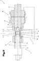
- the adjustment movement of the support shaft 37 described above can be carried out, for example, such that after releasing the positive connection from the axis end region facing the first drive shaft part 29 an adjustment device 40, for example with a cylinder-piston arrangement, is arranged on the end region of the support shaft 37 lying opposite this.
- an adjustment device 40 for example with a cylinder-piston arrangement
- the support shaft 37 is mounted slidably in the axial direction in the second drive shaft part 30, via the adjusting device 40, an axial displacement of the support shaft 37 in the in the Fig. 3 shown position.
- the adjusting device 40 communicates with the end of the support shaft 37 facing away from the first drive shaft part 29.
- the adjusting device 40 is also supported, optionally with the interposition of unspecified components, on the base frame 5. With appropriate actuation of the adjusting device 40, the axial adjustment of the support shaft 37 can take place.
- the driver rings 34 described above can serve, for example, to be able to form a same axial distance when changing the axial length of the friction wheel 4 by corresponding exchange or adaptation of the driver rings 34.
- the process or the method for changing at least one friction wheel 4 of the extrusion molding machine 1 which is connected to the drive unit 9 and can be rotated about the drive axis 8 can comprise at least the following steps and also constitute a solution according to the invention alone.
- the support shaft 37 is in the rotatably mounted on the base frame 5 second drive shaft part 30 to the from the base frame 5 rotatably mounted second drive shaft part 30 adjusted first drive shaft part 29 averted direction.
- the support shaft 37 is adjusted to an intermediate position, in which the friction wheel 4 is no longer penetrated by the support shaft 37.
- at least the axis end region of the support shaft 37 is located outside the cross section of the friction wheel 4.
- a common adjustment of the second drive shaft part 30 and the support shaft 37 guided therein takes place in the direction away from the first drive shaft part 29.
- the release of a voltage applied to the friction wheel 4 contact position of at least one of the drive shaft parts 29 and / or 30.
- the friction wheel 4 remains on the first drive shaft part 29 and can then be released with a corresponding release of this, in particular decoupled and removed from the extrusion press 1.
- the pressure roller 10 is first adjusted in the vertical direction in the direction away from the friction wheel 4 upwards. Subsequently, the pressure roller 10 can still be adjusted in the passage direction of the extruded material 3 or the profile 2 to be formed in a further distanced from the friction wheel 4 position.
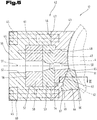
- Fig. 5 and 6 is a possible and possibly independent embodiment of the tool unit 12 is shown, again for like parts, the same reference numerals or component names as in the preceding Fig. 1 to 4 be used. In order to avoid unnecessary repetition, the detailed description in the previous ones will be used Fig. 1 to 4 referred or referred.
- the tool unit 12 described in more detail hereinbelow is designed for interaction with the extrusion molding machine 1 already described above, but it can also be used with a tool holding device 6 configured differently therefrom. Preferably, however, the tool unit 12 serves to cooperate with the tool holding device 6 and the associated gap width adjustment or adjustment.
- the tool unit 12 shown here is designed to be received in the tool holding device 6 described above and in turn comprises a receiving cage 42 which has a first receiving cage portion 43 arranged on the inlet side and a second receiving cage portion 44 arranged on the outlet side.
- the two receiving cage parts 43, 44 may further abut each other via connecting means 45, such as screws or the like, on facing end faces 46, 47 and be connected to each other.
- a receiving channel 48 passing through this in the direction of passage of the extruded material 3 is provided, in which at least one tool element 49 arranged on the inlet side is received or inserted.
- an extrusion channel 50 accommodating this is picked up by the extruded material 3 scraped off by the friction wheel 4 and already softened.
- the second receiving cage part 44 arranged downstream of the first receiving cage part 43 has a receiving space 52 which faces the first receiving cage part 43 and is open towards the first receiving cage part 43.
- the receiving space 52 at least one die 53 is received.
- the die 53 is arranged in the direction of passage of the extruded material 3 downstream of the tool element 49 arranged on the inlet side.
- the die 53 is provided with a shaping channel 54 which serves to shape the profile 2 to be produced.
- the expansion channel 50 and the shaping channel 54 define a profile axis 55 for the profile to be produced 2.
- the profile axis is rectilinear and aligned in a horizontal plane.
- the receiving space 52 is at the outlet side at least partially limited by a support surface 56. Subsequent to the receiving space 52, a passage opening 57 for the profile 2 emerging from the tool unit 12 is formed in the second receiving cage part 44. Furthermore, the matrix 53 is optionally supported with the interposition of at least one spacer element 58 on the support surface 56 delimiting the receiving space 52 on the outlet side.
- a corresponding constructional unit is formed, in which the female die 53, optionally the at least one spacer element 58, the tool element 49 arranged on the inlet side and the scraper element 51 are received therein are held to it.
- the receiving cage 42 in particular its second receiving cage portion 44 at its outlet end, a first bearing surface 59, which is aligned with respect to the profile axis 55 in a plane perpendicular thereto.
- the receiving space 52 has, at its lower side located in the insertion position, another bearing surface 60 which is angular with respect to the first bearing surface 59 and in particular at right angles thereto.
- the die 53 and optionally the spacer element 58 may have a cylindrical outer shape with respect to the profile axis 55 on its outer circumference.
- the receiving space 52 formed in the second receiving cage part 44 is then to be formed with a correspondingly opposite spatial form.
- at least the die 53, but preferably also the spacer element 58 can be received in the receiving space 52 formed in the second receiving cage part 44 in the axial direction. This can be done for example via a centering pin 61 shown in simplified, which is indicated in dashed lines. This is arranged in the outlet-side end region of the second receiving cage part 44 and extends in the direction of the first receiving cage part 43.
- receiving channel 48 can the tool member 49 and the receiving channel 48 to each other in the circumferential direction around the profile axis 55 seen having a form-fitting cooperating circumferential geometry. This could be done for example by a cylindrical shape with lateral flattening or a polygonal cross-sectional shape.
- a common receiving groove 62 is arranged or formed both in the inlet side arranged tool element 49 and in the first receiving cage portion 43.
- the receiving groove 62 is limited by at least one groove base 63, 64.
- the stripping element 51 is loosely inserted into the receiving groove 62 and supported on the at least one groove base 63, 64 load-bearing thereon.
- the scraping element 51 protrudes into the groove shown in the friction wheel 4 and deflects the softened extruded material 3 from the groove of the friction wheel 4 into the expansion channel 50 of the inlet-side tool element 49.
- the stripping element 51 is subject to high wear and is often replaced or replaced.
- an internal cooling of the stripping element 51 may also be provided so as to minimize the temperature load.
- the first groove base 63 is arranged in the tool element 49 arranged on the inlet side, and the second groove base 64 is arranged or formed in the first receiving cage part 43.
- the two groove base surfaces 63, 64 aligned toward each other in the direction of the outlet side arranged second receiving cage portion 44 and formed.
- At the stripping element 51 are aligned opposite first and second abutment surfaces 65, 66 form. Due to these mutually aligned groove base surfaces 63, 64, the stripping element 51 is pressed against this, whereby a kind of self-centering and mounting of the otherwise loose in the receiving groove 62 inserted scraper element 51 can be achieved.
- the lateral support takes place on the side surfaces of the receiving groove 62.
- a holding lug 67 may be formed on the stripping element 51 at its second receiving cage portion 44 facing and between the two contact surfaces 65, 66 formed end portion.
- the retaining lug 67 may be formed as a projecting nose and engage in a retaining neck receiving opening 68 formed opposite thereto.
- Fig. 7 is another possible and possibly independent embodiment of the tool unit 12 is shown, again for like parts, the same reference numerals or component names as in the preceding Fig. 1 to 6 be used. In order to avoid unnecessary repetition, the detailed description in the previous ones will be used Fig. 1 to 6 referred or referred.
- the receiving cage 42 with its two receiving cage parts 43, 44 is shown.
- the spacer element 58 and the die 53 can be accommodated.
- a corresponding alignment and adjustment of these two parts can be carried out analogously by means of the centering pin 61, as has already been described above.
Landscapes
- Engineering & Computer Science (AREA)
- Mechanical Engineering (AREA)
- Extrusion Moulding Of Plastics Or The Like (AREA)
- Press-Shaping Or Shaping Using Conveyers (AREA)
- Extrusion Of Metal (AREA)
- Automatic Assembly (AREA)
- Forging (AREA)
Priority Applications (1)
| Application Number | Priority Date | Filing Date | Title |
|---|---|---|---|
| PL18179253T PL3409391T3 (pl) | 2013-11-18 | 2014-11-17 | Zespół narzędziowy do wytłaczarki do ciągłego wytwarzania profilu z odkształcalnego materiału poddawanego wytłaczaniu |
Applications Claiming Priority (3)
| Application Number | Priority Date | Filing Date | Title |
|---|---|---|---|
| ATA50765/2013A AT515164B1 (de) | 2013-11-18 | 2013-11-18 | Werkzeugeinheit, Strangpressmaschine sowie Verfahren zum Wechseln eines Reibrades |
| EP14830369.6A EP3071346B1 (fr) | 2013-11-18 | 2014-11-17 | Presse a extrusion pour la fabrication continue de profiles a partir d'un materiau extrudable |
| PCT/AT2014/050274 WO2015070274A2 (fr) | 2013-11-18 | 2014-11-17 | Unité d'outil, extrudeuse et procédé de remplacement d'une roue à friction |
Related Parent Applications (1)
| Application Number | Title | Priority Date | Filing Date |
|---|---|---|---|
| EP14830369.6A Division EP3071346B1 (fr) | 2013-11-18 | 2014-11-17 | Presse a extrusion pour la fabrication continue de profiles a partir d'un materiau extrudable |
Publications (3)
| Publication Number | Publication Date |
|---|---|
| EP3409391A2 true EP3409391A2 (fr) | 2018-12-05 |
| EP3409391A3 EP3409391A3 (fr) | 2019-02-20 |
| EP3409391B1 EP3409391B1 (fr) | 2020-12-23 |
Family
ID=52394803
Family Applications (2)
| Application Number | Title | Priority Date | Filing Date |
|---|---|---|---|
| EP18179253.2A Active EP3409391B1 (fr) | 2013-11-18 | 2014-11-17 | Unité d'outil pour une machine d'extrusion destiné à la fabrication en continu d'un profilé d'une matière à extruder déformable |
| EP14830369.6A Active EP3071346B1 (fr) | 2013-11-18 | 2014-11-17 | Presse a extrusion pour la fabrication continue de profiles a partir d'un materiau extrudable |
Family Applications After (1)
| Application Number | Title | Priority Date | Filing Date |
|---|---|---|---|
| EP14830369.6A Active EP3071346B1 (fr) | 2013-11-18 | 2014-11-17 | Presse a extrusion pour la fabrication continue de profiles a partir d'un materiau extrudable |
Country Status (5)
| Country | Link |
|---|---|
| US (1) | US10376939B2 (fr) |
| EP (2) | EP3409391B1 (fr) |
| AT (1) | AT515164B1 (fr) |
| PL (2) | PL3409391T3 (fr) |
| WO (1) | WO2015070274A2 (fr) |
Families Citing this family (8)
| Publication number | Priority date | Publication date | Assignee | Title |
|---|---|---|---|---|
| US10300647B2 (en) | 2015-12-08 | 2019-05-28 | iMFLUX Inc. | System and method for continuous injection molding |
| US9937647B2 (en) | 2015-12-08 | 2018-04-10 | iMFLUX Inc. | Co-injection with continuous injection molding |
| AT518237B1 (de) * | 2016-01-15 | 2019-12-15 | Asmag Holding Gmbh | Reibradeinheit sowie Strangpressmaschine mit einer derartigen Reibradeinheit |
| CN107052070A (zh) * | 2017-04-26 | 2017-08-18 | 苏州罗普斯金铝业股份有限公司 | 一种组配工艺 |
| AT520712B1 (de) * | 2017-06-02 | 2019-10-15 | Asmag Holding Gmbh | Verfahren zur Abstandsregelung zwischen zwei Werkzeugkomponenten einer Strangpressmaschine |
| AT520033B1 (de) * | 2017-06-02 | 2022-01-15 | Asmag Holding Gmbh | Strangpressmaschine |
| CN113480860B (zh) * | 2021-07-22 | 2022-11-18 | 泰特耐特新材料科技有限公司 | 一种轮胎用钛酸盐片晶增强纤维材料及其制备方法 |
| CN114798787B (zh) * | 2022-05-13 | 2023-09-12 | 安徽金铂新材料科技有限公司 | 一种电机壳分流挤压装置 |
Family Cites Families (14)
| Publication number | Priority date | Publication date | Assignee | Title |
|---|---|---|---|---|
| US3839894A (en) * | 1973-05-14 | 1974-10-08 | Wean United Inc | Positioning apparatus for containers of extrusion presses |
| GB2103572A (en) | 1981-08-07 | 1983-02-23 | British Petroleum Co Plc | Winding a strut |
| GB2103527A (en) * | 1981-08-12 | 1983-02-23 | Atomic Energy Authority Uk | Continuous extrusion |
| JPS59223113A (ja) | 1983-06-03 | 1984-12-14 | Sumitomo Heavy Ind Ltd | 回転ホイ−ル式金属連続押出機 |
| NL8302003A (nl) * | 1983-06-06 | 1985-01-02 | Henricus Peter Marie Backus | Werkwijze en inrichting voor continue plastische vervorming van ductiele nonferrometalen. |
| US4823586A (en) * | 1987-12-31 | 1989-04-25 | Southwire Company | Conform product thermomechanical treatment |
| GB8915769D0 (en) | 1989-07-10 | 1989-08-31 | Bwe Ltd | Continuous extrusion apparatus |
| US5406818A (en) | 1991-11-12 | 1995-04-18 | Abb Power T & D Company | Opening apparatus having an alignment system for producing a continuous metal strip from a split-tube |
| JP2001340915A (ja) | 2000-05-29 | 2001-12-11 | Hitachi Cable Ltd | 連続押出装置 |
| GB2386334B (en) | 2002-02-14 | 2004-02-18 | Holton Machinery Ltd | Continuous extrusion using dynamic shoe positioning |
| JP5381349B2 (ja) | 2009-06-02 | 2014-01-08 | 三菱マテリアル株式会社 | 回転ホイール式連続押出装置及び金属押出材の製造方法 |
| CN101733298A (zh) * | 2009-12-28 | 2010-06-16 | 大连康丰科技有限公司 | 采用非圆形杆料生产大宽度铜带坯的连续挤压方法和设备 |
| JP5818918B2 (ja) | 2011-03-10 | 2015-11-18 | コモンウェルス サイエンティフィック アンド インダストリアル リサーチ オーガナイゼーション | 高温成形可能な非鉄金属の押し出し成形方法及び装置 |
| CN102294377B (zh) | 2011-09-06 | 2014-04-02 | 佛山市承安铜业有限公司 | 微晶挤压设备及其生产方法 |
-
2013
- 2013-11-18 AT ATA50765/2013A patent/AT515164B1/de active
-
2014
- 2014-11-17 PL PL18179253T patent/PL3409391T3/pl unknown
- 2014-11-17 WO PCT/AT2014/050274 patent/WO2015070274A2/fr not_active Ceased
- 2014-11-17 EP EP18179253.2A patent/EP3409391B1/fr active Active
- 2014-11-17 PL PL14830369T patent/PL3071346T3/pl unknown
- 2014-11-17 US US15/037,096 patent/US10376939B2/en active Active
- 2014-11-17 EP EP14830369.6A patent/EP3071346B1/fr active Active
Also Published As
| Publication number | Publication date |
|---|---|
| PL3409391T3 (pl) | 2021-07-12 |
| AT515164B1 (de) | 2023-01-15 |
| EP3071346B1 (fr) | 2018-06-27 |
| WO2015070274A2 (fr) | 2015-05-21 |
| EP3409391B1 (fr) | 2020-12-23 |
| EP3071346A2 (fr) | 2016-09-28 |
| AT515164A1 (de) | 2015-06-15 |
| US10376939B2 (en) | 2019-08-13 |
| WO2015070274A3 (fr) | 2015-09-17 |
| US20160361743A1 (en) | 2016-12-15 |
| EP3409391A3 (fr) | 2019-02-20 |
| PL3071346T3 (pl) | 2018-12-31 |
Similar Documents
| Publication | Publication Date | Title |
|---|---|---|
| EP3071346B1 (fr) | Presse a extrusion pour la fabrication continue de profiles a partir d'un materiau extrudable | |
| DE2953820C1 (de) | Abschervorrichtung fuer einzelne Glasposten | |
| EP3442784B1 (fr) | Presse radiale | |
| DE69127712T2 (de) | Revolverstantpresse | |
| DE19940744A1 (de) | Radialpresse | |
| DE3327258A1 (de) | Einrichtung und verfahren zum formen von ringen zu einem vorbestimmten profil | |
| EP2105292A1 (fr) | Dispositif de réglage de galet | |
| EP2853319A1 (fr) | Dispositif destiné au forgeage d'un bloc creux pré-percé | |
| EP0473951B1 (fr) | Dispositif pour monter l'outil sur le porte-outil d'une presse à refouler | |
| EP4124440B1 (fr) | Système d'outil à filière et dispositif d'extrusion-soufflage | |
| EP1345715B1 (fr) | Presse a forger dotee d'un dispositif de reglage situe cote matrice | |
| EP2886224B1 (fr) | Tête à rouler les filets | |
| EP3956084B1 (fr) | Tête de pose, presse pour tôle ou dispositif de pose pourvu de cette tête de pose et procédé d'assemblage d'un élément d'assemblage avec ladite tête de pose | |
| DE112009001413B4 (de) | Walzmaschine zum Umformen von metallischen und/oder eisenhaltigen Werkstücken mit verstellbaren Walzen | |
| DE102010060658B4 (de) | Walzmaschine zum Umformen von metallischen und/oder eisenhaltigen Werkstücken mit geklemmten Drehlagern und Verfahren zum Wechseln der Walzen oder der Walzenwerkzeuge der Walzmschine | |
| EP3912742B1 (fr) | Machine à extruder, ainsi que procédé de changement d'une roue de friction dans une machine à extruder | |
| EP4186613B1 (fr) | Mâchoire de moulage d'un outil de rétreinte rotatif permettant de former une pièce pouvant être déformée plastiquement, ainsi qu'outil de rétreinte rotatif pourvu de mâchoires de moulage | |
| AT518237B1 (de) | Reibradeinheit sowie Strangpressmaschine mit einer derartigen Reibradeinheit | |
| AT520712B1 (de) | Verfahren zur Abstandsregelung zwischen zwei Werkzeugkomponenten einer Strangpressmaschine | |
| DE29615649U1 (de) | Bearbeitungsmaschine für plattenförmige Werkstücke mit einem in einzelne Segmente unterteilten Niederhalter | |
| WO2025251099A1 (fr) | Dispositif de réglage pour moules de coulée | |
| DE10063560C2 (de) | Einrichtung zur Werkzeughöheneinstellung an Stanzpressen sowie Stanzpresse | |
| DE2645722A1 (de) | Reibungsschweissmaschine |
Legal Events
| Date | Code | Title | Description |
|---|---|---|---|
| PUAI | Public reference made under article 153(3) epc to a published international application that has entered the european phase |
Free format text: ORIGINAL CODE: 0009012 |
|
| STAA | Information on the status of an ep patent application or granted ep patent |
Free format text: STATUS: THE APPLICATION HAS BEEN PUBLISHED |
|
| AC | Divisional application: reference to earlier application |
Ref document number: 3071346 Country of ref document: EP Kind code of ref document: P |
|
| AK | Designated contracting states |
Kind code of ref document: A2 Designated state(s): AL AT BE BG CH CY CZ DE DK EE ES FI FR GB GR HR HU IE IS IT LI LT LU LV MC MK MT NL NO PL PT RO RS SE SI SK SM TR |
|
| PUAL | Search report despatched |
Free format text: ORIGINAL CODE: 0009013 |
|
| AK | Designated contracting states |
Kind code of ref document: A3 Designated state(s): AL AT BE BG CH CY CZ DE DK EE ES FI FR GB GR HR HU IE IS IT LI LT LU LV MC MK MT NL NO PL PT RO RS SE SI SK SM TR |
|
| RIC1 | Information provided on ipc code assigned before grant |
Ipc: B21C 23/21 20060101ALI20190114BHEP Ipc: B21C 25/02 20060101ALI20190114BHEP Ipc: B21C 23/00 20060101AFI20190114BHEP |
|
| STAA | Information on the status of an ep patent application or granted ep patent |
Free format text: STATUS: REQUEST FOR EXAMINATION WAS MADE |
|
| 17P | Request for examination filed |
Effective date: 20190820 |
|
| RBV | Designated contracting states (corrected) |
Designated state(s): AL AT BE BG CH CY CZ DE DK EE ES FI FR GB GR HR HU IE IS IT LI LT LU LV MC MK MT NL NO PL PT RO RS SE SI SK SM TR |
|
| GRAP | Despatch of communication of intention to grant a patent |
Free format text: ORIGINAL CODE: EPIDOSNIGR1 |
|
| STAA | Information on the status of an ep patent application or granted ep patent |
Free format text: STATUS: GRANT OF PATENT IS INTENDED |
|
| INTG | Intention to grant announced |
Effective date: 20200703 |
|
| GRAS | Grant fee paid |
Free format text: ORIGINAL CODE: EPIDOSNIGR3 |
|
| GRAA | (expected) grant |
Free format text: ORIGINAL CODE: 0009210 |
|
| STAA | Information on the status of an ep patent application or granted ep patent |
Free format text: STATUS: THE PATENT HAS BEEN GRANTED |
|
| AC | Divisional application: reference to earlier application |
Ref document number: 3071346 Country of ref document: EP Kind code of ref document: P |
|
| AK | Designated contracting states |
Kind code of ref document: B1 Designated state(s): AL AT BE BG CH CY CZ DE DK EE ES FI FR GB GR HR HU IE IS IT LI LT LU LV MC MK MT NL NO PL PT RO RS SE SI SK SM TR |
|
| REG | Reference to a national code |
Ref country code: GB Ref legal event code: FG4D Free format text: NOT ENGLISH |
|
| REG | Reference to a national code |
Ref country code: DE Ref legal event code: R096 Ref document number: 502014015139 Country of ref document: DE |
|
| REG | Reference to a national code |
Ref country code: AT Ref legal event code: REF Ref document number: 1347234 Country of ref document: AT Kind code of ref document: T Effective date: 20210115 |
|
| REG | Reference to a national code |
Ref country code: IE Ref legal event code: FG4D Free format text: LANGUAGE OF EP DOCUMENT: GERMAN |
|
| REG | Reference to a national code |
Ref country code: FI Ref legal event code: FGE |
|
| PG25 | Lapsed in a contracting state [announced via postgrant information from national office to epo] |
Ref country code: RS Free format text: LAPSE BECAUSE OF FAILURE TO SUBMIT A TRANSLATION OF THE DESCRIPTION OR TO PAY THE FEE WITHIN THE PRESCRIBED TIME-LIMIT Effective date: 20201223 Ref country code: NO Free format text: LAPSE BECAUSE OF FAILURE TO SUBMIT A TRANSLATION OF THE DESCRIPTION OR TO PAY THE FEE WITHIN THE PRESCRIBED TIME-LIMIT Effective date: 20210323 Ref country code: GR Free format text: LAPSE BECAUSE OF FAILURE TO SUBMIT A TRANSLATION OF THE DESCRIPTION OR TO PAY THE FEE WITHIN THE PRESCRIBED TIME-LIMIT Effective date: 20210324 |
|
| REG | Reference to a national code |
Ref country code: NL Ref legal event code: MP Effective date: 20201223 |
|
| PG25 | Lapsed in a contracting state [announced via postgrant information from national office to epo] |
Ref country code: BG Free format text: LAPSE BECAUSE OF FAILURE TO SUBMIT A TRANSLATION OF THE DESCRIPTION OR TO PAY THE FEE WITHIN THE PRESCRIBED TIME-LIMIT Effective date: 20210323 Ref country code: LV Free format text: LAPSE BECAUSE OF FAILURE TO SUBMIT A TRANSLATION OF THE DESCRIPTION OR TO PAY THE FEE WITHIN THE PRESCRIBED TIME-LIMIT Effective date: 20201223 Ref country code: SE Free format text: LAPSE BECAUSE OF FAILURE TO SUBMIT A TRANSLATION OF THE DESCRIPTION OR TO PAY THE FEE WITHIN THE PRESCRIBED TIME-LIMIT Effective date: 20201223 |
|
| PG25 | Lapsed in a contracting state [announced via postgrant information from national office to epo] |
Ref country code: HR Free format text: LAPSE BECAUSE OF FAILURE TO SUBMIT A TRANSLATION OF THE DESCRIPTION OR TO PAY THE FEE WITHIN THE PRESCRIBED TIME-LIMIT Effective date: 20201223 Ref country code: NL Free format text: LAPSE BECAUSE OF FAILURE TO SUBMIT A TRANSLATION OF THE DESCRIPTION OR TO PAY THE FEE WITHIN THE PRESCRIBED TIME-LIMIT Effective date: 20201223 |
|
| REG | Reference to a national code |
Ref country code: LT Ref legal event code: MG9D |
|
| PG25 | Lapsed in a contracting state [announced via postgrant information from national office to epo] |
Ref country code: SM Free format text: LAPSE BECAUSE OF FAILURE TO SUBMIT A TRANSLATION OF THE DESCRIPTION OR TO PAY THE FEE WITHIN THE PRESCRIBED TIME-LIMIT Effective date: 20201223 Ref country code: EE Free format text: LAPSE BECAUSE OF FAILURE TO SUBMIT A TRANSLATION OF THE DESCRIPTION OR TO PAY THE FEE WITHIN THE PRESCRIBED TIME-LIMIT Effective date: 20201223 Ref country code: CZ Free format text: LAPSE BECAUSE OF FAILURE TO SUBMIT A TRANSLATION OF THE DESCRIPTION OR TO PAY THE FEE WITHIN THE PRESCRIBED TIME-LIMIT Effective date: 20201223 Ref country code: RO Free format text: LAPSE BECAUSE OF FAILURE TO SUBMIT A TRANSLATION OF THE DESCRIPTION OR TO PAY THE FEE WITHIN THE PRESCRIBED TIME-LIMIT Effective date: 20201223 Ref country code: SK Free format text: LAPSE BECAUSE OF FAILURE TO SUBMIT A TRANSLATION OF THE DESCRIPTION OR TO PAY THE FEE WITHIN THE PRESCRIBED TIME-LIMIT Effective date: 20201223 Ref country code: PT Free format text: LAPSE BECAUSE OF FAILURE TO SUBMIT A TRANSLATION OF THE DESCRIPTION OR TO PAY THE FEE WITHIN THE PRESCRIBED TIME-LIMIT Effective date: 20210423 Ref country code: LT Free format text: LAPSE BECAUSE OF FAILURE TO SUBMIT A TRANSLATION OF THE DESCRIPTION OR TO PAY THE FEE WITHIN THE PRESCRIBED TIME-LIMIT Effective date: 20201223 |
|
| REG | Reference to a national code |
Ref country code: DE Ref legal event code: R097 Ref document number: 502014015139 Country of ref document: DE |
|
| PG25 | Lapsed in a contracting state [announced via postgrant information from national office to epo] |
Ref country code: IS Free format text: LAPSE BECAUSE OF FAILURE TO SUBMIT A TRANSLATION OF THE DESCRIPTION OR TO PAY THE FEE WITHIN THE PRESCRIBED TIME-LIMIT Effective date: 20210423 |
|
| PG25 | Lapsed in a contracting state [announced via postgrant information from national office to epo] |
Ref country code: IT Free format text: LAPSE BECAUSE OF FAILURE TO SUBMIT A TRANSLATION OF THE DESCRIPTION OR TO PAY THE FEE WITHIN THE PRESCRIBED TIME-LIMIT Effective date: 20201223 Ref country code: AL Free format text: LAPSE BECAUSE OF FAILURE TO SUBMIT A TRANSLATION OF THE DESCRIPTION OR TO PAY THE FEE WITHIN THE PRESCRIBED TIME-LIMIT Effective date: 20201223 |
|
| PLBE | No opposition filed within time limit |
Free format text: ORIGINAL CODE: 0009261 |
|
| STAA | Information on the status of an ep patent application or granted ep patent |
Free format text: STATUS: NO OPPOSITION FILED WITHIN TIME LIMIT |
|
| PG25 | Lapsed in a contracting state [announced via postgrant information from national office to epo] |
Ref country code: DK Free format text: LAPSE BECAUSE OF FAILURE TO SUBMIT A TRANSLATION OF THE DESCRIPTION OR TO PAY THE FEE WITHIN THE PRESCRIBED TIME-LIMIT Effective date: 20201223 |
|
| 26N | No opposition filed |
Effective date: 20210924 |
|
| PG25 | Lapsed in a contracting state [announced via postgrant information from national office to epo] |
Ref country code: ES Free format text: LAPSE BECAUSE OF FAILURE TO SUBMIT A TRANSLATION OF THE DESCRIPTION OR TO PAY THE FEE WITHIN THE PRESCRIBED TIME-LIMIT Effective date: 20201223 |
|
| PG25 | Lapsed in a contracting state [announced via postgrant information from national office to epo] |
Ref country code: SI Free format text: LAPSE BECAUSE OF FAILURE TO SUBMIT A TRANSLATION OF THE DESCRIPTION OR TO PAY THE FEE WITHIN THE PRESCRIBED TIME-LIMIT Effective date: 20201223 |
|
| PG25 | Lapsed in a contracting state [announced via postgrant information from national office to epo] |
Ref country code: IS Free format text: LAPSE BECAUSE OF FAILURE TO SUBMIT A TRANSLATION OF THE DESCRIPTION OR TO PAY THE FEE WITHIN THE PRESCRIBED TIME-LIMIT Effective date: 20210423 |
|
| PG25 | Lapsed in a contracting state [announced via postgrant information from national office to epo] |
Ref country code: MC Free format text: LAPSE BECAUSE OF FAILURE TO SUBMIT A TRANSLATION OF THE DESCRIPTION OR TO PAY THE FEE WITHIN THE PRESCRIBED TIME-LIMIT Effective date: 20201223 |
|
| REG | Reference to a national code |
Ref country code: CH Ref legal event code: PL |
|
| GBPC | Gb: european patent ceased through non-payment of renewal fee |
Effective date: 20211117 |
|
| PG25 | Lapsed in a contracting state [announced via postgrant information from national office to epo] |
Ref country code: LU Free format text: LAPSE BECAUSE OF NON-PAYMENT OF DUE FEES Effective date: 20211117 Ref country code: BE Free format text: LAPSE BECAUSE OF NON-PAYMENT OF DUE FEES Effective date: 20211130 |
|
| REG | Reference to a national code |
Ref country code: BE Ref legal event code: MM Effective date: 20211130 |
|
| PG25 | Lapsed in a contracting state [announced via postgrant information from national office to epo] |
Ref country code: LI Free format text: LAPSE BECAUSE OF NON-PAYMENT OF DUE FEES Effective date: 20211130 Ref country code: CH Free format text: LAPSE BECAUSE OF NON-PAYMENT OF DUE FEES Effective date: 20211130 |
|
| PG25 | Lapsed in a contracting state [announced via postgrant information from national office to epo] |
Ref country code: IE Free format text: LAPSE BECAUSE OF NON-PAYMENT OF DUE FEES Effective date: 20211117 Ref country code: GB Free format text: LAPSE BECAUSE OF NON-PAYMENT OF DUE FEES Effective date: 20211117 |
|
| PG25 | Lapsed in a contracting state [announced via postgrant information from national office to epo] |
Ref country code: CY Free format text: LAPSE BECAUSE OF FAILURE TO SUBMIT A TRANSLATION OF THE DESCRIPTION OR TO PAY THE FEE WITHIN THE PRESCRIBED TIME-LIMIT Effective date: 20201223 |
|
| PG25 | Lapsed in a contracting state [announced via postgrant information from national office to epo] |
Ref country code: HU Free format text: LAPSE BECAUSE OF FAILURE TO SUBMIT A TRANSLATION OF THE DESCRIPTION OR TO PAY THE FEE WITHIN THE PRESCRIBED TIME-LIMIT; INVALID AB INITIO Effective date: 20141117 |
|
| PG25 | Lapsed in a contracting state [announced via postgrant information from national office to epo] |
Ref country code: MK Free format text: LAPSE BECAUSE OF FAILURE TO SUBMIT A TRANSLATION OF THE DESCRIPTION OR TO PAY THE FEE WITHIN THE PRESCRIBED TIME-LIMIT Effective date: 20201223 |
|
| PG25 | Lapsed in a contracting state [announced via postgrant information from national office to epo] |
Ref country code: TR Free format text: LAPSE BECAUSE OF FAILURE TO SUBMIT A TRANSLATION OF THE DESCRIPTION OR TO PAY THE FEE WITHIN THE PRESCRIBED TIME-LIMIT Effective date: 20201223 |
|
| PG25 | Lapsed in a contracting state [announced via postgrant information from national office to epo] |
Ref country code: MT Free format text: LAPSE BECAUSE OF FAILURE TO SUBMIT A TRANSLATION OF THE DESCRIPTION OR TO PAY THE FEE WITHIN THE PRESCRIBED TIME-LIMIT Effective date: 20201223 |
|
| PGFP | Annual fee paid to national office [announced via postgrant information from national office to epo] |
Ref country code: DE Payment date: 20251118 Year of fee payment: 12 |
|
| PGFP | Annual fee paid to national office [announced via postgrant information from national office to epo] |
Ref country code: AT Payment date: 20251119 Year of fee payment: 12 |
|
| PGFP | Annual fee paid to national office [announced via postgrant information from national office to epo] |
Ref country code: FI Payment date: 20251118 Year of fee payment: 12 |
|
| PGFP | Annual fee paid to national office [announced via postgrant information from national office to epo] |
Ref country code: FR Payment date: 20251126 Year of fee payment: 12 |
|
| PGFP | Annual fee paid to national office [announced via postgrant information from national office to epo] |
Ref country code: PL Payment date: 20251006 Year of fee payment: 12 |