EP3415280A1 - Machine-outil à main avec un commutateur à palette - Google Patents
Machine-outil à main avec un commutateur à palette Download PDFInfo
- Publication number
- EP3415280A1 EP3415280A1 EP17177438.3A EP17177438A EP3415280A1 EP 3415280 A1 EP3415280 A1 EP 3415280A1 EP 17177438 A EP17177438 A EP 17177438A EP 3415280 A1 EP3415280 A1 EP 3415280A1
- Authority
- EP
- European Patent Office
- Prior art keywords
- switch
- paddle
- trigger
- power tool
- contact lever
- Prior art date
- Legal status (The legal status is an assumption and is not a legal conclusion. Google has not performed a legal analysis and makes no representation as to the accuracy of the status listed.)
- Granted
Links
Images




Classifications
-
- B—PERFORMING OPERATIONS; TRANSPORTING
- B25—HAND TOOLS; PORTABLE POWER-DRIVEN TOOLS; MANIPULATORS
- B25F—COMBINATION OR MULTI-PURPOSE TOOLS NOT OTHERWISE PROVIDED FOR; DETAILS OR COMPONENTS OF PORTABLE POWER-DRIVEN TOOLS NOT PARTICULARLY RELATED TO THE OPERATIONS PERFORMED AND NOT OTHERWISE PROVIDED FOR
- B25F5/00—Details or components of portable power-driven tools not particularly related to the operations performed and not otherwise provided for
- B25F5/02—Construction of casings, bodies or handles
-
- B—PERFORMING OPERATIONS; TRANSPORTING
- B24—GRINDING; POLISHING
- B24B—MACHINES, DEVICES, OR PROCESSES FOR GRINDING OR POLISHING; DRESSING OR CONDITIONING OF ABRADING SURFACES; FEEDING OF GRINDING, POLISHING, OR LAPPING AGENTS
- B24B23/00—Portable grinding machines, e.g. hand-guided; Accessories therefor
- B24B23/02—Portable grinding machines, e.g. hand-guided; Accessories therefor with rotating grinding tools; Accessories therefor
- B24B23/028—Angle tools
-
- B—PERFORMING OPERATIONS; TRANSPORTING
- B25—HAND TOOLS; PORTABLE POWER-DRIVEN TOOLS; MANIPULATORS
- B25F—COMBINATION OR MULTI-PURPOSE TOOLS NOT OTHERWISE PROVIDED FOR; DETAILS OR COMPONENTS OF PORTABLE POWER-DRIVEN TOOLS NOT PARTICULARLY RELATED TO THE OPERATIONS PERFORMED AND NOT OTHERWISE PROVIDED FOR
- B25F5/00—Details or components of portable power-driven tools not particularly related to the operations performed and not otherwise provided for
-
- H—ELECTRICITY
- H01—ELECTRIC ELEMENTS
- H01H—ELECTRIC SWITCHES; RELAYS; SELECTORS; EMERGENCY PROTECTIVE DEVICES
- H01H21/00—Switches operated by an operating part in the form of a pivotable member acted upon directly by a solid body, e.g. by a hand
- H01H21/02—Details
- H01H21/04—Cases; Covers
- H01H21/10—Casing of switch constituted by a handle serving a purpose other than the actuation of the switch
-
- H—ELECTRICITY
- H01—ELECTRIC ELEMENTS
- H01H—ELECTRIC SWITCHES; RELAYS; SELECTORS; EMERGENCY PROTECTIVE DEVICES
- H01H21/00—Switches operated by an operating part in the form of a pivotable member acted upon directly by a solid body, e.g. by a hand
- H01H21/02—Details
- H01H21/18—Movable parts; Contacts mounted thereon
- H01H21/22—Operating parts, e.g. handle
-
- H—ELECTRICITY
- H02—GENERATION; CONVERSION OR DISTRIBUTION OF ELECTRIC POWER
- H02K—DYNAMO-ELECTRIC MACHINES
- H02K7/00—Arrangements for handling mechanical energy structurally associated with dynamo-electric machines, e.g. structural association with mechanical driving motors or auxiliary dynamo-electric machines
- H02K7/14—Structural association with mechanical loads, e.g. with hand-held machine tools or fans
- H02K7/145—Hand-held machine tool
-
- H—ELECTRICITY
- H02—GENERATION; CONVERSION OR DISTRIBUTION OF ELECTRIC POWER
- H02P—CONTROL OR REGULATION OF ELECTRIC MOTORS, ELECTRIC GENERATORS OR DYNAMO-ELECTRIC CONVERTERS; CONTROLLING TRANSFORMERS, REACTORS OR CHOKE COILS
- H02P6/00—Arrangements for controlling synchronous motors or other dynamo-electric motors using electronic commutation dependent on the rotor position; Electronic commutators therefor
-
- H—ELECTRICITY
- H01—ELECTRIC ELEMENTS
- H01H—ELECTRIC SWITCHES; RELAYS; SELECTORS; EMERGENCY PROTECTIVE DEVICES
- H01H2235/00—Springs
- H01H2235/01—Spiral spring
Definitions
- the present disclosure relates to various features of a handheld grinder or similar power tool having a brushless electric motor.
- Some power tools include brushless electric motors. Power tools with brushless electric motors are used for woodworking and metalworking, for example. Such power tools include a power switching circuit that delivers power from a power supply to the motor, and a controller that manages the switching operation of the power switching circuit to control a speed of the motor.
- Conventional power tools also often include a power on/off switch disposed on the current path from the power supply to either the power switching circuit or the motor.
- switches are mechanically actuated by the user via, e.g., a trigger switch in drills or impact drivers, or a paddle switch or sliding switch in tools such as grinders. These switches actuate the power switch to make or break contact on the current path supplied to the motor.
- Such switches may be disposed on current paths to, for example, a controller that controls the switching operation of the power switching circuit, or another associated circuit component, and thus are rated to carry a smaller amount of current.
- the mechanically-actuated trigger, paddle, or sliding switches should be made to work with such on/off switches.
- a power tool including a housing, a motor disposed within the housing, an on/off switch having a contact tip disposed within the housing for activating the motor, a paddle switch coupled to the housing via a pivot member and having a paddle trigger engageable by a user, a switch contact lever disposed in selectable engagement with the contact tip of the on/off switch to activate and/or deactivate the on/off switch, and a biasing member disposed between the switch contact lever and the paddle switch to absorb a travel distance of the paddle trigger with respect to the switch contact lever.
- the switch contact lever is coupled to the paddle switch via a second pivot member.
- the paddle switch includes an inner body extending into the housing from the paddle trigger, and the second pivot member is coupled to the inner body.
- the switch contact lever is disposed between the paddle switch and the on/off switch.
- the switch contact lever includes a first spring post
- the paddle trigger includes a second spring post
- ends of the biasing member are disposed around the first spring post and the second spring post.
- the spring post is disposed to support the switch contact lever at an angular distance with respect to the paddle trigger in a default position of the paddle trigger.
- the switch contact lever moves with the paddle trigger at approximately the same angular travel distance.
- the switch contact lever engages and presses on the contact tip of the on/off switch to activate the on/off switch.
- the angular travel distance of the switch contact lever is smaller than the angular travel distance of the paddle trigger within the second angular travel range of the paddle trigger.
- the switch contact lever remains substantially in place in engagement with the contact tip of the on/off switch.
- the total angular travel range of the paddle trigger is in the range of 10-20 degrees.
- the first angular travel range of the paddle trigger is approximately 30-40% of the total angular travel range of the paddle trigger
- the second angular travel range of the paddle trigger is approximately 20-30% of the total angular travel range of the paddle trigger
- the third angular travel range of the paddle trigger is approximately 30-40% of the total angular travel range of the paddle trigger.
- the power tool further includes a paddle force lever disposed between the paddle switch and a portion of the housing to apply a biasing force on the paddle switch away from the housing.
- the paddle force lever is coupled to the paddle switch via a second pivot member.
- the power tool further includes a leg extending from the switch contact lever opposite the second pivot member, and the paddle switch engages the leg to rotate the switch contact lever away from the on/off switch when the paddle trigger is released.
- the paddle switch includes an engagement post projecting from an inner face of the paddle trigger that engages the leg when the paddle trigger is released.
- the housing includes an elongated housing arranged to receive a planar circuit board therein, and at least one cover that mates with the elongated housing around the planar circuit board.
- the pivot member is disposed to connect the paddle switch to the cover.
- the on/off switch is an analog logic switch capable of carrying voltage of up to 20 volts.
- the power tool includes a switching arrangement between a power supply and the motor, a controller configured to control a switching operation of the switching arrangement circuit to control an operation of the motor, a driver circuit disposed between the controller and the switching arrangement to provide voltage signals for controlling the switching operation of the switching arrangement, and a power supply regulator for supplying a voltage input to at least one of the driver circuit or the controller.
- the on/off switch is disposed on a path of the voltage input between the power supply regulator and at least one of the driver circuit or the controller.
- the switch contact lever may be coupled to the paddle switch via a second pivot member.
- a paddle switch may comprise an inner body extending into the housing from the paddle trigger, and the second pivot member is coupled to the inner body.
- the switch contact lever is disposed between the paddle switch and the on/off switch.
- the switch contact lever can include a first spring post, the paddle trigger includes a second spring post, and ends of the biasing member are disposed around the first spring post and the second spring post.
- the spring post can be disposed to support the switch contact lever at an angular distance with respect to the paddle trigger in a default position of the paddle trigger.
- the switch contact lever can move with the paddle trigger at approximately the same angular travel distance.
- the switch contact lever can engage and presses on the contact tip of the on/off switch to activate the on/off switch.
- the angular travel distance of the switch contact lever can be smaller than the angular travel distance of the paddle trigger within the second angular travel range of the paddle trigger.
- the switch contact lever can remain substantially in place in engagement with the contact tip of the on/off switch.
- the total angular travel range of the paddle trigger can be in the range of 10-20 degrees.
- the first angular travel range of the paddle trigger can be approximately 30-40% of the total angular travel range of the paddle trigger
- the second angular travel range of the paddle trigger can be approximately 20-30% of the total angular travel range of the paddle trigger
- the third angular travel range of the paddle trigger can be approximately 30-40% of the total angular travel range of the paddle trigger.
- the power tool can further comprise a paddle force lever disposed between the paddle switch and a portion of the housing to apply a biasing force on the paddle switch away from the housing.
- the paddle force lever can be coupled to the paddle switch via a second pivot member.
- the power tool can further comprise a leg extending from the switch contact lever opposite the second pivot member, and the paddle switch engages the leg to rotate the switch contact lever away from the on/off switch when the paddle trigger is released.
- the paddle switch may further comprise an engagement post projecting from an inner face of the paddle trigger that engages the leg when the paddle trigger is released.
- the housing may comprise an elongated housing arranged to receive a planar circuit board therein, and at least one cover that mates with the elongated housing around the planar circuit board.
- the pivot member may be disposed to connect the paddle switch to the cover.
- the on/off switch can be an analog logic switch capable of carrying voltage of up to 20 volts.
- the power tool can further comprise:
- the on/off switch can be disposed on a path of the voltage input between the power supply regulator and at least one of the driver circuit or the controller.
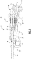
- the power tool 10 includes an elongated housing 12, a motor 16 ( Figure 3 ), a module casing or power module support structure 18 ( Figure 3 ), and a planar circuit board 20 ( Figure 3 ).
- the housing 12 defines a cavity 21 ( Figure 3 ) and includes a motor case 22 and a handle portion 23.
- the motor case 22 is positioned at one end 12-1 of the housing 12 and includes a gear case 24 and a sliding switch 25.
- the gear case 24 includes a gearset 11, an output shaft 27, and a threaded opening 28.
- the gearset 11 is positioned within the gear case 24 and is drivably coupled to the motor 16.
- the output shaft 27 is drivably connected to the gearset 11 within the gear case 24 and extends perpendicular to the longitudinal axis of the housing 12.
- the output shaft 27 is also coupled to a grinding or a cutting disc (not shown) via a flange (not shown). The grinding disk may be removed and replaced with a new grinding disk.
- a user of the power tool 10 may replace the existing grinding disk with a new grinding disk after the existing disk wears out.
- An adjustable guard 29 may cover at least a portion of the rotating disk to obstruct sparks and debris generated during operation of the power tool 10.
- the threaded opening 28 allows for selectively attaching a side-handle (not shown) to enable two-handed operation.
- the sliding switch 25 is positioned on a side of the motor case 22 and engages a power on/off switch 24 (described below) to allow for the user to turn the power tool 10 ON and OFF.
- the handle portion 23 extends axially from the motor case 22 toward a second end 12-2 of the housing 12 and includes a first cover 23a and a second cover 23b.
- the first and the second covers 23a, 23b are secured together around the module casing 18 and the planar circuit board 20 disposed within the cavity 21 of the handle portion 23.
- the second cover 23b includes a support member 30 protruding outwardly therefrom and positioned at the second end 12-2 of the housing 12.
- the support member 30 includes openings 31 extending therethrough to allow incoming air to enter the cavity 21.
- An AC power cord 32 is attached to the handle portion 23 at the second end 12-2 of the housing 12 to supply electric power to the power tool 10.
- the power tool 10 may include a chuck that is configured to receive a drill bit or a screw bit, thereby allowing the power tool 10 to be used as a power drill or a power screw driver.
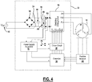
- FIG. 4 depicts a schematic that illustrates an example of a motor drive circuit 33.
- the motor drive circuit 33 is comprised generally of a controller 34, a switching arrangement 36, a driver circuit 38, a rectifier 40, a DC bus capacitor 42, a power supply 44, and an auxiliary switch path 46.
- the motor drive circuit 33 may further include positioned sensors 48, such as Hall Effect sensors that are configured to detect rotational motion of the motor 16 and generate a signal indicative of the rotational motion.
- the signal may have a periodic waveform whose magnitude may vary in accordance with the rotational position of the motor 16. It should be noted, that other types of positional sensors may be alternatively utilized and should not be limited to Hall Effect sensors.
- An AC supply 52 delivers an alternating current to the rectifier 40 through, for example, the power cord 32.
- the rectifier 40 converts the alternating current into a direct current that is outputted to a DC bus 54 (i.e., power line/bus).
- the output of the rectifier 40 may be pulsating DC signal and not a pure DC signal.
- the DC bus capacitor 42 is electrically connected in parallel with the rectifier 40.
- the switching arrangement 36 is electrically connected with the DC bus capacitor 42 and may receive the pure DC signal or the substantially pure DC signal from the DC bus capacitor 42 via the DC bus 54.
- the switching arrangement 36 includes a plurality of motor switches that, when switched on, deliver the DC current to the motor 16 on phase voltage lines 55 (PV, PW, PU).
- the motor switches may be IGBTs or FETs, for example.
- the switching arrangement 36 may be further defined as a three-phase inverter bridge although other arrangements are contemplated by this disclosure.
- the DC bus capacitor 42 may be a link capacitor having relatively small capacitance and does not act to smoothen the full-wave rectified AC voltage.
- the DC bus capacitor 42 is a bypass capacitor that removes the high frequency noise from the bus voltage.
- the auxiliary switch path 46 is electrically coupled in parallel with the rectifier 40 and the link capacitor 42, and is electrically connected between the rectifier 40 and the switching arrangement 36.
- the auxiliary switch path 46 includes an auxiliary capacitor 56 and a switch 58 positioned in series with the auxiliary capacitor 56.
- the switch 58 may be a controlled switch, such as a MOSFET or an IGBT, in an embodiment.
- the switch 58 may be controlled by software programmed into the controller 34 or another programmable microcontroller. Alternatively, the switch 58 may be controlled by hardware, such as a switch control circuit 60, described in detail below.
- the switch 58 When the switch 58 is closed, the auxiliary capacitor 56 is connected parallel to the DC bus capacitor 42.
- the driver circuit 38 interfaces with the motor switches of the switching arrangement 36.
- the driver circuit 38 controls the state of the motor switches.
- the driver circuit 38 is shown as being separate from the switching arrangement 36.
- the driver circuit 38 and the switching arrangement 36 may be a single integrated circuit which may be commercially available from various manufacturers.
- the switching arrangement 36 which may include IGBTs, and the driver circuit 38 may be a part of an integrated power module.
- the controller 34 interfaces with the driver circuit 38 and may generate PWM signals to control the motor 16. In this embodiment, the controller 34 receives power from the power supply regulator 44. In an alternate embodiment, the controller 34 may receive power directly from the rectifier 40.
- the power supply regulator 44 is electrically connected in parallel with the rectifier 40 and operates to power the driver circuit 38 via a power on/off switch 26.
- the power on/off switch 26 is positioned between the power supply regulator 44 and the driver circuit 38.
- the power on/off switch 26 is an analog logic switch capable of carrying a voltage of up to 20V from the power supply regulator 44 to the gate driver circuit 38.
- the power on/off switch 26 may be a current-carrying power switch activated via a normally-open contact member. When the contact member is pressed down, the power on/off switch switches to the ON-position.
- the driver circuit 38 When the power on/off switch 26 is switched to the ON-position, the driver circuit 38 receives power from the power supply regulator 44. When the driver circuit 38 receives power, the driver circuit 38 is able to control the state of the motor switches 55 and the motor 16 is on.
- the driver circuit 38 does not receive power from the power supply regulator 44.
- the driver circuit 38 is not able to control the state of the motor switches 55 and the electric motor is off.
- the power on/off switch 26 is electrically connected between the rectifier 40 and the driver circuit 38.
- the power on/off switch 26 is positioned such that the power from the AC power supply 52 does not pass through the power on/off switch 26. Furthermore, the current being drawn by the motor 16 does not pass through the power on/off switch 26.
- the current passing through the power on/off switch 26 is the current being drawn by the driver circuit 38 and the current being drawn by the driver circuit 38 is lower than the current being drawn by the electric motor 16.
- the power on/off switch 26 may be engaged via a sliding switch 25 as shown in Fig. 1 .
- the power on/off switch 26 may alternatively be engaged via a paddle switch 200, as shown in Fig. 5 and described below.
- a sliding switch includes a slider button arranged outside the power tool housing that is attached to a link member disposed within the power tool housing. The actuation of the sliding switch by the user causes the link member to make or break contact with the power on/off switch to turn the power tool on or off.
- a paddle switch includes a paddle trigger that pivots around a pivot post, and an arm that extends from the paddle switch across the pivot posts. The actuation of the paddle trigger causes the arm the make or break contact with the power on/off switch to turn the tool on or off.
- Such conventional sliding switches and paddle switch are suitable for engaging conventional on/off power switches that are disposed on the current path from the power supply.
- Such power switches tend to be relatively large, with a contact portion that has a travel distance of, for example, 4 to 8 mm.
- the contact portion of on/off switch 24 in Fig. 5 of the '976 patent can turn on after the face 56 of the paddle switch travels 2-3 mm, but can absorb another 4 mm of travel distance by face 56.
- Such power switches provide some degree of flexibility for the travel distance of the slider button (for a sliding switch) or the paddle trigger (for a paddle switch).
- the power on/off switch 26 is an analog logic switch capable of carrying a voltage of up to 20V from the power supply regulator 44 to the gate driver circuit 38.
- the power on/off switch 26 may be much smaller in size than conventional high-current power switches, and as such, may be provided with a contact portion that can absorb a significantly smaller travel distance.
- the contact portion of the power on/off switch 26 may only have a total travel distance of less than 1 mm.
- the sliding switch 25 may be coupled to a link member (not shown) that is made of flexible material capable of absorbing extra the travel distance of the sliding switch 25.
- the contact face of the link member may be bendable to absorb the travel distance of the sliding switch of up to 10 mm. In this manner, if the contact face of the link member comes into contact with the contact portion of the on/off switch 26 after, for example, 5mm of the sliding switch 25 travel, and turns ON the on/off switch after, for example, 6mm of sliding switch 25 travel, it bends to absorb the remaining travel distance of the sliding switch 25 without damaging the on/off switch 26. In this manner, the on/off switch turns ON approximately half-way within the travel distance of the sliding switch 25.
- the paddle switch 200 may be coupled to an actuation assembly 220, as described herein with reference to Figs. 6-9 .
- paddle switch 200 may be incorporated into handle cover 23b, as shown in Fig. 5 and the perspective inner views of Figs. 6 and 7 .
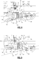
- Figs. 8 and 9 depicts cross-sectional views of the power tool 10 including the paddle switch 200 and the actuation assembly 220.
- the paddle switch 200 includes a paddle trigger 202 connected to the handle cover 23b (or another part of the power tool housing 12) via a pivot member 204.
- the paddle trigger 202 may include a trigger lock 206 pivotably extending from the paddle trigger 202 and is spring-loaded to a locked position ( Fig. 8 ), in which it prevents the paddle trigger 202 from being pressed by the user from its default position.
- the trigger lock 206 is engaged by the user and rotated with respect to the paddle trigger 202 to an unlocked position ( Fig. 9 ) before the paddle trigger 202 can be fully pressed by the user to activate the power tool 10.
- the trigger lock 206 springs back into its locked position, and as it slides against the handle cover 23b, it forces the paddle trigger 202 away from the handle cover 23b to its default position.
- the actuation assembly 220 includes a switch contact lever 222 arranged to engage a contact tip 26a of the on/off switch 26.
- the switch contact lever 222 is positioned between the paddle trigger 202 and the on/off switch 26.
- a biasing member 224 such as a compression spring, is disposed between the paddle trigger 202 and the switch contact lever 222.
- Switch contact lever 222 is rotatable around a pivot member 226.
- pivot member 226 pivotably connects the switch contact lever 222 to an inner body portion 208 of the paddle switch 200 that extends into the cover 23b from the paddle trigger 202.
- the pivot member 226 may pivotably connect the switch contact lever 222 to an inner wall of the handle cover 23b or another part of the power tool housing 12.
- the pivot member 226 may be the same (i.e., along the same axis) as the pivot member 204.
- pivot members 204 and 226 may be disposed along two different axes.
- the actuation assembly 220 includes a spring post 210 disposed on an inner face of the paddle trigger 202 within the inner body portion 208.
- the switch contact lever 222 similarly includes a spring post 228 facing spring post 210 of the actuation assembly 200.
- the biasing member 224 is disposed around the spring posts 210 and 228 so as to biasedly locate the switch contact lever 222 at an angular distance with respect to the paddle trigger 202.
- Disposition of the biasing member 224 between the paddle trigger 202 and the switch contact lever 222 allows the switch contact lever 222 to move with the actuation of the paddle trigger 202 until the switch contact lever 222 comes into contact with the contact tip 26a of on/off switch 26 and turns on the on/off switch 26, without damaging the on/off switch 26 with further travel of the paddle trigger 202. This is discussed below in detail.
- the actuation assembly 220 also includes a paddle force lever 240 disposed adjacent the switch contact lever 222.
- the paddle force lever 240 may be coupled to inner body portion 208 of the paddle switch 200 via pivot member 226.
- paddle force lever 240 may be coupled to the paddle switch 220 via a separate pivot member.
- the paddle force lever 240 is spring-loaded with respect to the paddle trigger 202 via a biasing member 242.
- a tip 244 of the paddle force lever 240 engages a portion of the housing 12 (e.g., an outer wall of the motor case 22), exerting a biasing force on the paddle trigger 202 away from the housing 12 to return the paddle switch 200 to its default position when it is released by the user.
- a leg 230 extending downwardly towards the paddle switch 200.
- the paddle switch 200 includes a corresponding engagement post 212 projecting from an inner face of the paddle trigger 202 adjacent the spring post 210 proximate the leg 230.
- the engagement post 212 engages the leg 230 so as to rotate the switch contact lever 222 away from the on/off switch 26.
- the engagement post 212 does not engage the leg 230 when the paddle switch 200 is pressed.
- the total angular travel range ⁇ of the paddle trigger 202 may be, in an embodiment, approximately 10-20 degrees, and in an example, approximately 15 degrees.
- a first angular travel range of the paddle trigger 202 e.g., 0 to 6 degrees
- the switch contact lever 222 moves freely (at approximately the same angular travel distance) with the paddle trigger 202 until it comes into contact with the on/off switch 26.
- a second angular travel range of the paddle trigger 202 e.g., between 6 to 10 degrees
- the switch contact lever 222 engages and presses on the contact tip 26a of the on/off switch 26 to turn it on.
- the compression force of the biasing member 224 is sufficient to allow the switch contact lever 222 to actuate the contact tip 26a of the on/off switch 26, but may absorb some of the impact.
- the angular travel distance of the switch contact lever 222 is smaller than the angular travel distance of the paddle trigger 202 within the second angular travel range. Thereafter, within a third angular travel range of the paddle trigger 202 (e.g., 10 to 15 degrees), the switch contact lever 222 remains substantially in place in contact with the on/off switch 26 while the biasing member 224 absorbs the over-travel distance of the paddle trigger 202.
- the biasing fore of the spring is overcome by the on/off switch 26 within the third angular travel range so the switch contact lever 222 does not damage the on/off switch 26.
- the on/off switch 26 turns on within approximately 40-70% of the travel distance of the paddle trigger 202 and the biasing member 224 absorbs the remaining travel distance of the paddle trigger 202 to prevent damage to the on/off switch 26.
- first, second, third, etc. may be used herein to describe various elements, components, regions, layers and/or sections, these elements, components, regions, layers and/or sections should not be limited by these terms. These terms may be only used to distinguish one element, component, region, layer or section from another region, layer or section. Terms such as “first,” “second,” and other numerical terms when used herein do not imply a sequence or order unless clearly indicated by the context. Thus, a first element, component, region, layer or section discussed below could be termed a second element, component, region, layer or section without departing from the teachings of the example embodiments.
- spatially relative terms such as “inner,” “outer,” “beneath,” “below,” “lower,” “above,” “upper,” and the like, may be used herein for ease of description to describe one element or feature's relationship to another element(s) or feature(s) as illustrated in the figures.
- Spatially relative terms may be intended to encompass different orientations of the device in use or operation in addition to the orientation depicted in the figures. For example, if the device in the figures is turned over, elements described as “below” or “beneath” other elements or features would then be oriented “above” the other elements or features.
- the example term “below” can encompass both an orientation of above and below.
- the device may be otherwise oriented (rotated 90 degrees or at other orientations) and the spatially relative descriptors used herein interpreted accordingly.
Landscapes
- Engineering & Computer Science (AREA)
- Mechanical Engineering (AREA)
- Power Engineering (AREA)
- Portable Power Tools In General (AREA)
- Microelectronics & Electronic Packaging (AREA)
Applications Claiming Priority (1)
| Application Number | Priority Date | Filing Date | Title |
|---|---|---|---|
| US15/622,808 US10818450B2 (en) | 2017-06-14 | 2017-06-14 | Paddle switch |
Publications (2)
| Publication Number | Publication Date |
|---|---|
| EP3415280A1 true EP3415280A1 (fr) | 2018-12-19 |
| EP3415280B1 EP3415280B1 (fr) | 2021-12-01 |
Family
ID=59152710
Family Applications (1)
| Application Number | Title | Priority Date | Filing Date |
|---|---|---|---|
| EP17177438.3A Active EP3415280B1 (fr) | 2017-06-14 | 2017-06-22 | Machine-outil à main avec un commutateur à palette |
Country Status (2)
| Country | Link |
|---|---|
| US (1) | US10818450B2 (fr) |
| EP (1) | EP3415280B1 (fr) |
Cited By (4)
| Publication number | Priority date | Publication date | Assignee | Title |
|---|---|---|---|---|
| EP3678154A1 (fr) * | 2019-01-03 | 2020-07-08 | Defond Components Limited | Système de verrouillage destiné à être utilisé avec un ensemble de déclenchement d'un dispositif électrique |
| EP4008492A1 (fr) * | 2020-12-04 | 2022-06-08 | Hilti Aktiengesellschaft | Poignée pour machine-outil, machine-outil et son procédé de mise sous tension, de mise hors tension et de verrouillage |
| US12459079B2 (en) | 2020-12-04 | 2025-11-04 | Hilti Aktiengesellschaft | Power tool having a disk-shaped tool and a guard plate for protecting against flying sparks |
| US12569955B2 (en) | 2020-12-04 | 2026-03-10 | Hilti Aktiengesellschaft | Power tool having a front handle and a regulating unit |
Families Citing this family (9)
| Publication number | Priority date | Publication date | Assignee | Title |
|---|---|---|---|---|
| DE102016125435A1 (de) * | 2016-12-22 | 2018-06-28 | C. & E. Fein Gmbh | Handwerkzeugmaschine |
| US12162113B2 (en) * | 2018-09-14 | 2024-12-10 | Makita Corporation | Tool with accessory detection |
| DE102019216865A1 (de) * | 2019-10-31 | 2021-05-06 | Robert Bosch Gmbh | Handwerkzeugmaschine |
| WO2022009495A1 (fr) * | 2020-07-10 | 2022-01-13 | 株式会社マキタ | Outil de travail et outil électrique |
| CN112038137B (zh) * | 2020-09-23 | 2025-05-23 | 格力博(江苏)股份有限公司 | 开关组件及电动工具 |
| EP4342638A4 (fr) * | 2021-05-21 | 2025-02-12 | Globe (Jiangsu) Co., Ltd. | Outil électrique portatif |
| EP4223457B1 (fr) * | 2022-02-02 | 2024-12-11 | C. & E. Fein GmbH | Boitier pour une machine-outil portative électrique |
| EP4368350B1 (fr) * | 2022-11-08 | 2025-01-29 | Andrea Valentini | Outil électrique manuel de polissage ou de ponçage |
| US20250144830A1 (en) * | 2023-11-08 | 2025-05-08 | Black & Decker Inc. | Oscillating tool |
Citations (4)
| Publication number | Priority date | Publication date | Assignee | Title |
|---|---|---|---|---|
| DE2944750A1 (de) * | 1979-11-06 | 1981-05-21 | Metabowerke GmbH & Co, 7440 Nürtingen | Sicherheitsschalter |
| US4879438A (en) * | 1988-08-01 | 1989-11-07 | Ryobi Motor Products Corp. | Lock-on/lock-off switch for power tool |
| US5428197A (en) * | 1993-06-01 | 1995-06-27 | Ryobi Motor Products Corp. | Electric tool actuator switch |
| US8087976B2 (en) | 2005-05-13 | 2012-01-03 | Black & Decker Inc. | Trigger assembly for angle grinder |
Family Cites Families (383)
| Publication number | Priority date | Publication date | Assignee | Title |
|---|---|---|---|---|
| US394417A (en) | 1888-12-11 | Poele | ||
| DE118339C (fr) | ||||
| DE155280C (fr) | ||||
| DE123407C (fr) | ||||
| DE311993C (fr) | ||||
| DE225343C (fr) | ||||
| DE131551C (fr) | ||||
| DE178451C (fr) | ||||
| DE1073606B (de) | 1960-01-21 | Wilhelm Bender, CaIw (WÜrtt.) | Elektrisches Handwerkszeug mit von einer anderen Stelle herangeführter Kühlluft | |
| DE341238C (fr) | ||||
| DE122029C (fr) | ||||
| US731740A (en) | 1902-03-24 | 1903-06-23 | Gen Electric | Commutator-brush. |
| DE429619C (de) | 1920-08-15 | 1926-05-31 | Siemens Schuckertwerke G M B H | Buerstenhalter mit unter Federkraft stehendem, schwingendem Tragarm |
| DE482136C (de) | 1927-12-17 | 1929-09-07 | Sachsenwerk Licht & Kraft Ag | Kuehlluftreinigungseinrichtung fuer elektrische Maschinen mit Durchzugsbelueftung, bei der die Kuehlluft mittels eines Ventilators in das Maschineninnere gesaugt wird |
| US1971790A (en) | 1932-06-22 | 1934-08-28 | Arthur W Mall | Portable power tool |
| US2079143A (en) | 1935-01-19 | 1937-05-04 | Albertson & Co Inc | Sanding machine |
| US2201420A (en) | 1937-09-13 | 1940-05-21 | Wodack Electric Tool Corp | Abrading machine |
| US2192845A (en) | 1937-09-28 | 1940-03-05 | Gen Electric | Power unit |
| DE736475C (de) | 1940-06-20 | 1943-06-18 | Graetz Ag | Anordnung eines Wellenlagers in dem verjuengten Gehaeuse von Elektromotoren |
| US2348341A (en) | 1940-07-29 | 1944-05-09 | Chicago Electric Mfg Co | Motor |
| DE881831C (de) | 1942-09-01 | 1953-07-02 | Siemens Ag | Schleifbuerstenhalterung fuer Kommutatoren oder elektrische Schleifringanordnungen |
| DE923803C (de) | 1952-10-15 | 1955-02-21 | Ringsdorff Werke Gmbh | Buerstenhalter mit Buerste |
| US2987636A (en) | 1953-07-09 | 1961-06-06 | Sunbeam Corp | Electric mixer |
| DE944976C (de) | 1955-02-18 | 1956-06-28 | Joachim Csaki Dipl Ing | Filter fuer luftgekuehlte Maschine, insbesondere Elektrohandwerkzeugmaschine |
| DE1007870B (de) | 1956-01-30 | 1957-05-09 | Licentia Gmbh | Durch einen geschlossenen, mantelgekuehlten Kommutatormotor angetriebenes Elektrowerkzeug mit Aussenbelueftung |
| DE1006950B (de) | 1956-02-06 | 1957-04-25 | Alb Urbahn & Comp Werkzeug Und | Mittels Drehstrommotor angetriebenes Elektrowerkzeug |
| DE1030443B (de) | 1956-05-07 | 1958-05-22 | Wilhelm Bender | Elektromotor mit Staubfiltereinrichtung |
| US2905266A (en) | 1957-08-16 | 1959-09-22 | Torit Mfg Company | Separators |
| DE1046169B (de) | 1957-09-12 | 1958-12-11 | Wilhelm Bender | Elektromotor mit Staubfiltereinrichtung |
| US3077340A (en) | 1958-08-25 | 1963-02-12 | Sunbeam Corp | Electric mixer |
| DE1110740B (de) | 1959-11-06 | 1961-07-13 | Bosch Gmbh Robert | Schutzisolierte elektrische Handwerkzeugmaschine mit Lagerschild und Getriebegehaeuse aus Metall |
| DE1843271U (de) | 1961-03-04 | 1961-12-14 | Schmid & Wezel | Intensiv-belueftung speziell fuer drehstromhandmotoren. |
| CH398768A (de) | 1961-11-13 | 1966-03-15 | Heemaf N V Aktiengesellschaft | Elektrische Maschine mit Luftkühlung und einem Staubabscheider |
| DE1154863B (de) | 1962-07-17 | 1963-09-26 | Wilhelm Bender | UEber den gesamten aeusseren Umfang eines Elektromotors, insbesondere fuer handgetragene Werkzeugmaschinen, sich erstreckendes Grossflaechenstaubfilter |
| CH406888A (de) | 1962-11-19 | 1966-01-31 | Suhner Willy | Elektro-Winkelhandschleifgerät mit Lüftung |
| US3305281A (en) | 1963-07-19 | 1967-02-21 | Champ Items Inc | Idler arm repair kit |
| NL133349C (fr) | 1963-12-30 | |||
| US3325948A (en) | 1964-03-11 | 1967-06-20 | Skil Corp | Belt sander |
| US3266535A (en) | 1964-06-01 | 1966-08-16 | Singer Co | Safety blade clamping means for portable power saws |
| CH456301A (de) | 1965-11-19 | 1968-07-15 | Mets Owerke Kg Closs Rauch & S | Elektrisch angetriebene Bohrmaschine |
| US3474575A (en) | 1967-01-18 | 1969-10-28 | Black & Decker Mfg Co | Housing and handle construction for a belt-type sander |
| US3535829A (en) | 1968-05-21 | 1970-10-27 | Singer Co | Belt cleaners for belt sanders |
| DE1763401A1 (de) | 1968-05-21 | 1971-08-05 | Schunk & Ebe Gmbh | Buerstenhalter fuer elektrische Maschinen |
| IL32256A (en) | 1968-06-27 | 1972-10-29 | Scm Corp | Compositions containing a beta-di-lower alkylamino lower alkylene thioether or a salt thereof,and their use as herbicides |
| GB1165526A (en) | 1968-06-28 | 1969-10-01 | Standard Telephones Cables Ltd | Improvements in or relating to Automatic Telephone Exchanges |
| US3530337A (en) | 1968-11-06 | 1970-09-22 | Thomas Moore | Electrical motor overload indicator and voltage cutout device |
| DE1952876A1 (de) | 1969-10-21 | 1971-03-18 | Ymos Metallwerke Wolf & Becker | Kraftfahrzeugtuerschloss |
| ZA703543B (en) | 1969-11-14 | 1971-01-27 | Magneti Marelli Spa | A frame for electric low capacity motors,provided with covers retained by small,deformed wings |
| US3797336A (en) | 1970-03-02 | 1974-03-19 | W Howe | Quick connect nut |
| DE7010521U (de) | 1970-03-21 | 1971-08-26 | Bosch Gmbh Robert | Abschaltkohlebuerste. |
| DE2039793A1 (de) | 1970-08-04 | 1972-02-10 | Danow George Prof Dipl Ing | Buerstenapparat mit kastenloser Fuehrung und selbsteinstellbarer Buerste |
| DE7031833U (de) | 1970-08-26 | 1971-04-15 | Heid & Co Gmbh Kg Kohlebuerste | Halterung von kohlebuersten, insbesondere fuer schleifringe |
| DE2147927B2 (de) | 1971-09-25 | 1975-02-06 | Licentia Patent-Verwaltungs-Gmbh, 6000 Frankfurt | Spulenhalter zum festlegen des wickelkopfes eines feldspulenpakets an einem elektromotor |
| DE2156770C3 (de) | 1971-11-16 | 1974-06-20 | Hermann 7031 Maichingen Hefner | Vorrichtung zur lösbaren Befestigung einer Schleifscheibe oder dergleichen auf einer Treibspindel |
| US3731556A (en) | 1971-11-17 | 1973-05-08 | Cincinnati Milacron Inc | Dynamic balancing apparatus |
| DE2158598B2 (de) | 1971-11-26 | 1974-05-09 | Metabowerke Kg, Closs, Rauch & Schnizler, 7440 Nuertingen | Schmiervorrichtung für Getriebe mit Betrieb in allen Lagen |
| US3824745A (en) | 1972-08-21 | 1974-07-23 | A Hutchins | Suction system for abrading tool |
| US3760570A (en) | 1972-09-05 | 1973-09-25 | Black & Decker Mfg Co | Centrifugally responsive brake for rotary tool |
| DE2316323C3 (de) | 1973-04-02 | 1975-12-04 | Hermann 8183 St Quirin Schock | Abdichtende Rohrdurchführung an einer im Erdreich zu verlegenden Leitung |
| US3854020A (en) | 1973-06-29 | 1974-12-10 | Black & Decker Mfg Co | Trigger mechanism for hand-operated power device including stationary locking device which provides lock-off and lock-on operation |
| US3847233A (en) | 1973-06-29 | 1974-11-12 | Black & Decker Mfg Co | Trigger mechanism for hand-operated power device providing automatic lock-off and manual lock-on operation |
| US3873796A (en) | 1973-07-06 | 1975-03-25 | Black & Decker Mfg Co | Trigger mechanism for hand-operated power device including independently operable locking devices providing automatic lock off and manual lock-on operation |
| US3872951A (en) | 1973-11-06 | 1975-03-25 | Black & Decker Mfg Co | Spindle locking mechanism for rotary power device |
| US3961433A (en) | 1974-06-21 | 1976-06-08 | The Raymond Lee Organization Inc. | Picture poster viewer |
| US3899852A (en) | 1974-08-23 | 1975-08-19 | Singer Co | Spindle drive assembly for a surface-treating machine |
| US4007401A (en) | 1974-09-09 | 1977-02-08 | Westinghouse Electric Corporation | Current sensitive circuit protection system |
| US4020359A (en) | 1975-03-24 | 1977-04-26 | Davy Powergas Limited | Electrical control system |
| US3999176A (en) | 1975-04-07 | 1976-12-21 | Westinghouse Electric Corporation | Indicator light circuit providing normal and emergency indication |
| GB1519421A (en) | 1976-02-18 | 1978-07-26 | Trico Folberth Ltd | Brush mountings |
| DE2626003A1 (de) | 1976-06-10 | 1977-12-22 | Schulte Elektrotech | Mehrpoliger druckschalter mit ueberstromausloesung und unterspannungs- bzw. phasenausfallschutz |
| CH607574A5 (en) | 1976-08-13 | 1978-08-31 | Wachendorf L & Co Ag | Brush holder for electrical machines |
| NL7711072A (nl) | 1976-10-23 | 1978-04-25 | Textima Ag | Pers, in het bijzonder voor metaalbewerking. |
| DE7802306U1 (de) | 1977-02-10 | 1978-05-03 | Valentini, Guido, Vermezzo, Mailand (Italien) | Transportable, kreisende, elektrische schleifmaschine |
| DE7709148U1 (de) | 1977-03-24 | 1977-07-14 | Christian Geyer Gmbh & Co, 8500 Nuernberg | Abstandshalter für Leitungsdrähte in Dachständerrohren |
| DE7728401U1 (de) | 1977-09-14 | 1979-07-19 | Marton, Miksa, Windsor, Ontario (Kanada) | Tellerhandschleifmaschine |
| DE2850120A1 (de) | 1977-11-21 | 1979-05-23 | Black & Decker Mfg Co | Schalter-betaetigungseinrichtung |
| US4145848A (en) | 1978-01-24 | 1979-03-27 | Hutchins Manufacturing Co. | Rotary abrading tool |
| DE2813956B1 (de) | 1978-03-31 | 1979-04-26 | Siemens Ag | Kollektormotor mit einer in einer OEffnung des Motorgehaeuses fixierbaren Kunststoff-Buerstentragplatte |
| US4232414A (en) | 1978-07-10 | 1980-11-11 | Cooper Industries, Inc. | Free-wheeling overspeed grinder device |
| US4186288A (en) | 1978-09-01 | 1980-01-29 | Stackpole Components Company | Slide switch |
| JPS5928151B2 (ja) | 1978-11-04 | 1984-07-11 | ファナック株式会社 | 電動機駆動用インバ−タ回路の保護方式 |
| US4205732A (en) | 1979-03-07 | 1980-06-03 | Ingersoll-Rand Company | Muffler for portable pneumatic tool |
| DE2919669A1 (de) | 1979-05-16 | 1980-11-20 | Licentia Gmbh | Spannmutter fuer winkelschleifer |
| US4250587A (en) | 1979-07-02 | 1981-02-17 | Beck John W Jr | Scrubbing device |
| DE2927331A1 (de) | 1979-07-06 | 1981-02-05 | Bosch Gmbh Robert | Buerstenhalter mit buerstenabhebevorrichtung |
| DE3001907C2 (de) | 1980-01-19 | 1982-11-18 | Licentia Patent-Verwaltungs-Gmbh, 6000 Frankfurt | Einrichtung zum Arretieren der Antriebsspindel von Winkelschleifern und dergleichen handgeführter Elektrowerkzeuge |
| DE3004316C2 (de) | 1980-02-06 | 1983-12-29 | Skf Kugellagerfabriken Gmbh, 8720 Schweinfurt | Lagerung einer Welle eines Maschinenelementes |
| US4278371A (en) | 1980-02-29 | 1981-07-14 | Milwaukee Electric Tool Corporation | Safety interlock for electro-magnetic drill stand |
| US4295295A (en) | 1980-03-17 | 1981-10-20 | Tyco Industries, Inc. | Pick-up shoe and motor contact assembly for toy vehicle |
| NL8003635A (nl) | 1980-06-24 | 1982-01-18 | Noord Ver Metaal | In de hand te houden inrichting voor het bijwerken van de klauwen van een of tweehoevige dieren, zoals koeien. |
| DE3023803A1 (de) | 1980-06-25 | 1982-01-21 | Siemens AG, 1000 Berlin und 8000 München | Kollektormotor |
| DE3023691A1 (de) | 1980-06-25 | 1982-01-21 | Robert Bosch Gmbh, 7000 Stuttgart | Schalter mit einem bedienmittel, insbesondere an einer handwerkzeugmaschine |
| DE8016761U1 (de) | 1980-06-25 | 1982-06-24 | Robert Bosch Gmbh, 7000 Stuttgart | Schalter mit einem Bedienmittel, insbesondere an einer Handwerkzeugmaschine |
| JPS57501020A (fr) | 1980-07-21 | 1982-06-10 | ||
| US4334332A (en) | 1980-08-06 | 1982-06-15 | Downs Edgar S | Motor-driven cap-gripper and can-opener |
| DE3031915A1 (de) | 1980-08-23 | 1982-04-08 | Robert Bosch Gmbh, 7000 Stuttgart | Vorrichtung zum feststellen der abnutzung der kohlebuerste eines elektromotors |
| US4343502A (en) | 1980-10-09 | 1982-08-10 | Ingersoll-Rand Company | Doorknob construction |
| US4434586A (en) | 1980-12-03 | 1984-03-06 | Robert Bosch Gmbh | Machine tool, especially a hand-held power tool with a turnable clamping element for clamping a tool on the tool spindle |
| DE3110912A1 (de) | 1981-03-20 | 1982-09-30 | Licentia Patent-Verwaltungs-Gmbh, 6000 Frankfurt | Spannvorrichtung fuer die schleifscheibe eines winkelschleifers |
| JPS57171601U (fr) | 1981-04-24 | 1982-10-28 | ||
| DE3118831A1 (de) | 1981-05-12 | 1983-01-27 | Hans 8801 Schillingsfürst Heinlein | Filteranordnung |
| US4400995A (en) | 1981-09-23 | 1983-08-30 | Milwaukee Electric Tool Corporation | Spindle lock with impacting capability |
| CH653280A5 (de) | 1981-10-08 | 1985-12-31 | Ceka Elektrowerkzeuge Ag & Co | Schaltvorrichtung fuer den antriebsmotor eines elektrowerkzeuges. |
| US4536670A (en) | 1981-12-14 | 1985-08-20 | Morganite Incorporated | Electrical brushes with wear sensors |
| NL8200652A (nl) | 1982-02-18 | 1983-09-16 | Skil Nederland Nv | Elektromotor met verbeterde borstelkonstruktie. |
| DE8214078U1 (de) | 1982-05-14 | 1982-10-07 | Uhde Gmbh, 4600 Dortmund | Abstandshalter fuer rohrleitungen |
| JPS5923125U (ja) | 1982-08-03 | 1984-02-13 | アルプス電気株式会社 | スライドスイツチ |
| US4476602A (en) | 1982-08-13 | 1984-10-16 | Black & Decker, Inc. | Portable electric scrubber |
| JPS5930653U (ja) | 1982-08-20 | 1984-02-25 | マブチモ−タ−株式会社 | 小型モ−タのブラシ装置 |
| JPS5937859U (ja) | 1982-08-30 | 1984-03-09 | マブチモ−タ−株式会社 | ブラシ装置 |
| JPS5949380A (ja) | 1982-09-14 | 1984-03-21 | Sanyo Electric Co Ltd | ポンプ装置 |
| DE3317425A1 (de) | 1983-05-13 | 1984-08-09 | Daimler-Benz Ag, 7000 Stuttgart | Halterung fuer ein bearbeitungswerkzeug an einem roboterkopf |
| US4467896A (en) | 1983-06-17 | 1984-08-28 | Black & Decker Inc. | Locking mechanism for a rotary power machine |
| DE8317913U1 (de) | 1983-06-21 | 1984-11-29 | Robert Bosch Gmbh, 7000 Stuttgart | Vorrichtung zum arretieren der schleifspindel von winkelschleifern |
| DE3328955A1 (de) | 1983-08-11 | 1985-02-21 | Robert Bosch Gmbh, 7000 Stuttgart | Winkelschleifer mit einer sicherheitskupplung |
| DE3341874C1 (de) | 1983-09-08 | 1984-07-19 | Schulte-Elektrotechnik GmbH & Co KG, 5880 Lüdenscheid | Schalteranordnung mit Nullspannungsauslösung |
| DE8327966U1 (de) | 1983-09-29 | 1984-01-26 | Karl M. Reich Maschinenfabrik GmbH, 7440 Nürtingen | Schaltschieber fuer elektrowerkzeuge |
| JPS60152247A (ja) | 1984-01-20 | 1985-08-10 | Toshiba Corp | インバ−タ付可変速モ−タ |
| DE3467827D1 (en) | 1984-08-13 | 1988-01-07 | Siemens Ag | Thermic overload protection for a commutator or slipring-motor |
| WO1986001936A1 (fr) | 1984-09-11 | 1986-03-27 | Heinrich Kopp Gmbh & Co. Kg | Boitier de commutation pour un interrupteur (de protection) du moteur et dispositif de declenchement pour installation dans des appareils electriques |
| DE8427601U1 (de) | 1984-09-19 | 1985-05-30 | Siemens AG, 1000 Berlin und 8000 München | Hammer-buerstenhaltersystem fuer einen kommutatormotor |
| US4550277A (en) | 1984-09-24 | 1985-10-29 | Black & Decker Inc. | Overload detection and warning system for electric motors in power tools and the like |
| DE3501947A1 (de) | 1985-01-22 | 1986-07-24 | Apag Elektronik AG, Dübendorf, Zürich | Elektrowerkzeug, insbesondere winkelschleifer |
| DE8504518U1 (de) | 1985-02-18 | 1985-05-15 | Papst-Motoren GmbH & Co KG, 7742 St Georgen | Vorrichtung zur zugentlasteten unterbringung der litzenanschluesse bei elektro-kleinmotoren |
| US4604538A (en) | 1985-02-19 | 1986-08-05 | General Motors Corporation | Air cooling for diode-rectified alternating current generators |
| US4770316A (en) | 1985-02-25 | 1988-09-13 | Black & Decker Inc. | Power device housing with lubricant anti-wicking facility |
| DE3512365A1 (de) | 1985-04-04 | 1986-10-16 | C. & E. Fein Gmbh & Co, 7000 Stuttgart | Handgefuehrtes elektrowerkzeug mit einer bremseinrichtung |
| DE8525046U1 (de) | 1985-09-02 | 1986-06-26 | Siemens AG, 1000 Berlin und 8000 München | Bürstenanordnung für Kommutatormotore |
| DE3531309A1 (de) | 1985-09-02 | 1987-03-05 | Siemens Ag | Buerstenanordnung fuer kommutatormotore |
| JPH0323824Y2 (fr) | 1985-12-09 | 1991-05-23 | ||
| DE3546394A1 (de) | 1985-12-31 | 1987-07-02 | Metabowerke Kg | Durchzugsbeluefteter elektromotor |
| DE8601684U1 (de) | 1986-01-23 | 1987-05-21 | Siemens AG, 1000 Berlin und 8000 München | Kühlgebläse für eine elektrische Maschine |
| DE3607377A1 (de) | 1986-03-06 | 1987-09-10 | Metabowerke Kg | Elektromotorisch angetriebener schleifer |
| CH673356A5 (fr) | 1986-04-14 | 1990-02-28 | Portescap | |
| DE8705640U1 (de) | 1986-06-27 | 1987-10-29 | Schulte-Elektrotechnik GmbH & Co KG, 5880 Lüdenscheid | Schalter mit Nullspannungsauslösung |
| IT8622437V0 (it) | 1986-07-02 | 1986-07-02 | Valentini Guido | Utensile elettrico manuale con motore e condotto di scarico della polvere inclusi nell'impugnatura. |
| DE3623555A1 (de) | 1986-07-12 | 1988-02-04 | Fein C & E | Befestigungseinrichtung fuer scheibenfoermige werkzeuge an der werkzeugspindel einer tragbaren elektrowerkzeugmaschine |
| DE3638952A1 (de) | 1986-11-14 | 1988-05-26 | Marquardt Gmbh | Elektrischer schalter |
| DE8632779U1 (de) | 1986-12-06 | 1987-02-05 | Metabowerke GmbH & Co, 7440 Nürtingen | Druchzugsbelüfteter Elektromotor |
| US4765099A (en) | 1986-12-11 | 1988-08-23 | Tanner John G | Sanding and dust collecting apparatus |
| DE3643067A1 (de) | 1986-12-17 | 1988-06-23 | Bosch Gmbh Robert | Spanneinrichtung zum axialen festspannen eines werkzeuges, insbesondere einer scheibe |
| DE3644441A1 (de) | 1986-12-24 | 1988-07-07 | Bosch Gmbh Robert | Spanneinrichtung zum loesbaren befestigen eines werkzeuges, insbesondere einer scheibe |
| DE3700968A1 (de) | 1987-01-15 | 1988-08-04 | Bosch Gmbh Robert | Spanneinrichtung zum axialen festspannen eines werkzeuges, insbesondere einer scheibe |
| US4742257A (en) | 1987-01-29 | 1988-05-03 | General Motors Corporation | Totally enclosed fan cooled induction motor with improved cooling |
| US5100275A (en) | 1987-05-20 | 1992-03-31 | Schirrmacher Wendell E | Quick locking fasteners |
| DE3718891A1 (de) | 1987-06-05 | 1988-12-22 | Bayer Ag | Mischungen aus polyarylensulfiden und polyestern und deren verwendung |
| DE3722629C2 (de) | 1987-07-09 | 1995-01-19 | Metabowerke Kg | Elektrowerkzeug mit Bremseinrichtung |
| GB2207296A (en) | 1987-07-20 | 1989-01-25 | Johnson Electric Ind Mfg | Brush gear for an electric motor |
| DE3724747A1 (de) | 1987-07-25 | 1989-02-02 | Fein C & E | Schleifgeraet mit staubabsaugeinrichtung |
| DE3736535A1 (de) | 1987-10-28 | 1989-05-18 | Hoffmann Elektrokohle | Schleifkontaktanordnung, insbesondere fuer eine kohlebuerste |
| DE3741484C1 (de) | 1987-12-08 | 1989-08-24 | Fein C & E | Handwerkzeugmaschine mit automatischer Arretierung der Arbeitsspindel |
| DE3741536A1 (de) | 1987-12-08 | 1989-06-22 | Erhard Pauls | Bremsvorrichtung zur abbremsung von rotierenden maschinenelementen wie z. b. des rotors einer hand-winkelschleifmaschine |
| DE3809930A1 (de) | 1988-03-24 | 1989-10-05 | Bosch Gmbh Robert | Exzenterschleifer |
| GB8812292D0 (en) | 1988-05-24 | 1988-06-29 | Black & Decker Inc | Improvements in/relating to power tools |
| JPH0217961A (ja) | 1988-07-06 | 1990-01-22 | Ig Tech Res Inc | 塗装装置 |
| DE3841181A1 (de) | 1988-12-07 | 1990-06-13 | Bosch Gmbh Robert | Handwerkzeugmaschine mit einer mehrteiligen handbetaetigbaren schnellspanneinrichtung |
| DE3828954A1 (de) | 1988-08-26 | 1990-03-08 | Licentia Gmbh | Einrichtung zur stillstandsbremsung eines mit einem winkelgetriebe ausgeruesteten elektrowerkzeugs |
| DE3844617A1 (de) | 1988-08-26 | 1990-03-22 | Licentia Gmbh | Elektrowerkzeugmaschine mit einer kombinierten einrichtung zur stillstandsbremsung und zum spannen des werkzeugs |
| DE8811964U1 (de) | 1988-09-21 | 1989-07-20 | Siemens AG, 1000 Berlin und 8000 München | Drehzahlmeßvorrichtung für einen Kommutatormotor |
| DE8812072U1 (de) | 1988-09-23 | 1989-07-20 | Siemens AG, 1000 Berlin und 8000 München | Funkentstörter Kommutatormotor, insbesondere Kraftfahrzeug-Bordmotor |
| DE3836317A1 (de) | 1988-10-25 | 1990-04-26 | Vdo Schindling | Buerstenanordnung fuer einen elektromotor |
| GB2226709B (en) | 1988-12-30 | 1993-05-26 | Johnson Electric Ind Mfg | Terminal arrangement for an electric motor |
| US4876797A (en) | 1989-01-17 | 1989-10-31 | Alvaro Zapata | Reduced vibration portable gas operated hand saw |
| DE3902874A1 (de) | 1989-02-01 | 1990-08-09 | Fein C & E | Adapter zum befestigen eines zusatzwerkzeugs |
| DE8905006U1 (de) | 1989-04-20 | 1990-02-15 | Siemens AG, 1000 Berlin und 8000 München | Bürstenhalter, insbesondere Hammer-Bürstenhalter, für einen Kommutatormotor |
| DE3916495A1 (de) | 1989-05-20 | 1990-11-22 | Bosch Gmbh Robert | Handwerkzeug mit einem getriebegehaeuse mit dichtring |
| US5028826A (en) | 1989-06-02 | 1991-07-02 | Mitsubishi Denki K.K. | Fan arrangement for a vehicular AC generator |
| DE3922514A1 (de) | 1989-07-08 | 1991-01-17 | Licentia Gmbh | Einrichtung zur verbesserung der kuehlung des kollektors von elektrowerkzeugen |
| ATE116490T1 (de) | 1989-07-15 | 1995-01-15 | Kress Elektrik Gmbh & Co | Elektrowerkzeug. |
| DE4004464A1 (de) | 1989-07-15 | 1991-01-24 | Kress Elektrik Gmbh & Co | Elektrowerkzeug |
| ATE117473T1 (de) | 1989-07-15 | 1995-02-15 | Kress Elektrik Gmbh & Co | Schaltvorrichtung für elektrische umschaltung von elektrowerkzeugen. |
| IL91283A0 (en) | 1989-08-11 | 1990-03-19 | Gerard O Reilly | Grinding tool and spacer assembly for use therein |
| US4932163A (en) | 1989-08-29 | 1990-06-12 | Chilton Douglas L | Dust control system for an abrasive grinder |
| DE8910426U1 (de) | 1989-08-31 | 1990-07-05 | Siemens AG, 1000 Berlin und 8000 München | Bürstenhalter für einen Kommutatormotor |
| US5114317A (en) | 1989-10-23 | 1992-05-19 | Sundstrand Corporation | Low weight fan with internal cooling |
| US4967516A (en) | 1989-12-13 | 1990-11-06 | Ryobi Motor Products Corp. | Debris collection system for a surface treating tool |
| JPH03230736A (ja) | 1990-02-01 | 1991-10-14 | Matsushita Electric Ind Co Ltd | Acサーボモータ |
| DE4003029A1 (de) | 1990-02-02 | 1991-08-08 | Bosch Gmbh Robert | Handgefuehrte werkzeugmaschine mit radialgeblaese |
| DE4008161C1 (en) | 1990-03-15 | 1991-05-23 | Telefunken Electronic Gmbh, 7100 Heilbronn, De | Integrated circuitry projecting and controlling electrical appts. - has voltage limiter delivering pulse signal to counter if mains voltage is applied in-front of main switch |
| DE4107431A1 (de) | 1990-03-15 | 1991-09-19 | Telefunken Electronic Gmbh | Schaltung zum schutz und zum steuern elektrischer geraete |
| DE4102014C2 (de) | 1990-03-28 | 1998-04-30 | Atlas Copco Elektrowerkzeuge | Handgeführte Elektrowerkzeugmaschine mit Überlastkupplung |
| SE465960B (sv) | 1990-05-04 | 1991-11-25 | Atlas Copco Tools Ab | Vibrationsdaempad handhaallen rotationsslipmaskin |
| US5038523A (en) | 1990-05-08 | 1991-08-13 | The United States Of America As Represented By The Secretary Of The Navy | Seawater hydraulic rotary disk tool |
| CH680174A5 (fr) | 1990-05-23 | 1992-06-30 | Weber Ag | |
| DE4016774A1 (de) | 1990-05-25 | 1991-11-28 | Bosch Gmbh Robert | Von hand fuehrbare elektrische werkzeugmaschine |
| GB2244868B (en) | 1990-06-05 | 1994-03-30 | Johnson Electric Sa | Temperature control in an electric motor |
| US5051552A (en) | 1990-07-16 | 1991-09-24 | Ilinois Tool Works Inc. | Slide selector switch mechanism |
| EP0471876B1 (fr) | 1990-08-23 | 1994-06-08 | Siemens Aktiengesellschaft | Unité d'entraînement à moteur-réducteur, notamment entraînement de lève-glaces pour véhicule automobile |
| HUT70006A (en) | 1990-09-12 | 1995-09-28 | Matthews | Fastener particularly for grinding wheel |
| DE59101383D1 (de) | 1991-01-16 | 1994-05-19 | Fein C & E | Tragbare Schleifmaschine mit Schnellspanneinrichtung. |
| JPH04102783U (ja) | 1991-02-15 | 1992-09-04 | 日東工器株式会社 | Dcバツテリ駆動型ハンド工具 |
| DE4105340C2 (de) | 1991-02-21 | 1993-09-30 | Atlas Copco Elektrowerkzeuge | Handgeführter Winkelschleifer mit einer Bremsanordnung und einer eine Stirnverzahnung oder dergleichen formschlüssige Verbindung aufweisenden Einrichtung zum Sichern des Spannflansches gegen selbsttätiges Lösen beim Bremsvorgang |
| US5227950A (en) | 1991-03-01 | 1993-07-13 | Westinghouse Electric Corp. | Shaft grounding brush and holder |
| US5207028A (en) | 1991-05-17 | 1993-05-04 | Black & Decker Inc. | Tool element subassembly and method of manufacturing same |
| JP3244718B2 (ja) | 1991-05-22 | 2002-01-07 | 株式会社マキタ | 回転工具における回転刃具の固止装置 |
| DE4119325A1 (de) | 1991-06-12 | 1992-12-17 | Licentia Gmbh | Motorisch angetriebenes werkzeug |
| DE4119941A1 (de) | 1991-06-17 | 1993-01-07 | Frischmuth & Freitag Diamant U | Verfahren und anordnung zum schutz eines elektrischen antriebsmotors eines elektrowerkzeugs |
| EP0521259B1 (fr) | 1991-07-05 | 1994-07-27 | C. & E. FEIN GmbH & Co. | Machine-outil portative |
| US5144182A (en) | 1991-09-04 | 1992-09-01 | Onan Corporation | Skewed rotor assembly |
| US5464365A (en) | 1991-09-21 | 1995-11-07 | Robert Bosch Gmbh | Motor-driven hand-held machine tool |
| DE9112104U1 (de) | 1991-09-27 | 1993-01-28 | Robert Bosch Gmbh, 7000 Stuttgart | Vorrichtung zum Fördern von Kraftstoff aus einem Vorratstank zur Brennkraftmaschine eines Kraftfahrzeuges |
| DE9112975U1 (de) | 1991-10-18 | 1993-02-11 | Bär Elektrowerke GmbH & Co KG, 5885 Schalksmühle | Elektrisches Schaltergerät, insbesondere Wippenschalter für Haushaltsgeräte |
| IT221984Z2 (it) | 1991-10-29 | 1994-12-29 | Taf Srl | Disco abrasivo per macchine smerigliatrici, con mezzi di aggancio perfezionati |
| GB9123502D0 (en) | 1991-11-06 | 1992-01-02 | Black & Decker Inc | Sanding apparatus |
| DE9116586U1 (de) | 1991-11-11 | 1993-07-15 | Siemens AG, 8000 München | Durchführung für elektrische Leitungen |
| US5357179A (en) | 1992-06-19 | 1994-10-18 | Pace, Incorporated | Handheld low voltage machining tool |
| DE4220227A1 (de) | 1992-06-20 | 1993-12-23 | Bosch Gmbh Robert | Laufrad für einen Radiallüfter |
| DE9208940U1 (de) | 1992-07-03 | 1993-11-04 | Robert Bosch Gmbh, 70469 Stuttgart | Handwerkzeugmaschine mit Staubabsaugung |
| DE4233729A1 (de) | 1992-10-07 | 1994-04-14 | Bosch Gmbh Robert | Exzentertellerschleifer mit Schleiftellerbremse |
| WO1994007041A1 (fr) | 1992-09-11 | 1994-03-31 | Norman Leslie Matthews | Ecrou auto-bloquant |
| DE4233727A1 (de) | 1992-10-07 | 1994-04-14 | Bosch Gmbh Robert | Exzentertellerschleifer |
| DE9213624U1 (de) | 1992-10-09 | 1992-12-03 | Bsg-Schalttechnik Gmbh & Co Kg, 72336 Balingen | Elektrisches Gerät mit Schutzeinrichtung |
| CH683166A5 (de) | 1992-10-09 | 1994-01-31 | Karl Meier | Vorrichtung zum Entfernen von flächigen Belagstoffen. |
| US5218790A (en) | 1992-11-12 | 1993-06-15 | Huang Kan Chi | Pneumatically operated debris-removable grinding tool |
| FR2698032B1 (fr) | 1992-11-16 | 1995-10-06 | Metabowerke Gmbh | Dispositif de serrage rapide destine au serrage axial d'un outil en forme de disque. |
| WO1994013964A1 (fr) | 1992-12-10 | 1994-06-23 | Norman Leslie Matthews | Attache amelioree |
| US5437173A (en) | 1993-02-18 | 1995-08-01 | Truth Division Of Spx Corporation | Window lock with indicator |
| DE4305317C2 (de) | 1993-02-20 | 1995-10-12 | Metabowerke Kg | Schnellspanneinrichtung zum axialen Festspannen eines scheibenförmigen Werkzeugs |
| DE4306009C2 (de) | 1993-02-26 | 1996-05-09 | Fein C & E | Absaugeinrichtung für eine Flächenschleifmaschine |
| WO1995000288A1 (fr) | 1993-06-24 | 1995-01-05 | Norman Leslie Matthews | Fixation d'element d'outil a la broche filetee d'un outil a moteur |
| JPH0768464A (ja) | 1993-09-03 | 1995-03-14 | Hitachi Koki Co Ltd | 固定側フランジ |
| DE4336620C2 (de) | 1993-10-27 | 1997-07-03 | Fein C & E | Elektrowerkzeug mit einer nur bei ausgeschaltetem Motor betätigbaren Spannvorrichtung |
| US5419737A (en) | 1993-10-28 | 1995-05-30 | Ryobi Motor Products Corp. | Random orbital sanding machine having a removable debris container |
| DE4337023B4 (de) | 1993-10-29 | 2007-08-09 | Robert Bosch Gmbh | Motorgetriebene Handwerkzeugmaschine |
| DE4341214C2 (de) | 1993-12-03 | 1996-11-07 | Kloeckner Moeller Gmbh | Auslöseeinheit für Leistungs- oder Schutzschalter |
| DE4341931A1 (de) | 1993-12-09 | 1995-06-14 | Bosch Gmbh Robert | Maschine mit einem umlaufenden Teil |
| US5580302A (en) | 1994-02-28 | 1996-12-03 | Black & Decker Inc. | Random orbit sander having air directing baffle |
| DE4407418C2 (de) | 1994-03-03 | 1998-02-19 | Black & Decker Inc | Schalteranordnung, insbesondere für eine Oberfräse |
| JP3333627B2 (ja) | 1994-04-06 | 2002-10-15 | 株式会社マキタ | 回転研削工具のツール固止装置 |
| CN1072996C (zh) | 1994-05-03 | 2001-10-17 | 诺顿公司 | 角度打磨机用附件 |
| PL187063B1 (pl) | 1994-05-20 | 2004-05-31 | Eti Technologies Inc | Urządzenie do usuwania niewyważenia w członie obrotowym i sposób usuwania niewyważenia w członie obrotowym |
| US5563461A (en) | 1994-06-10 | 1996-10-08 | Emerson Electric Co. | Motor fan baffle |
| JPH0811045A (ja) | 1994-06-30 | 1996-01-16 | Shinano Seisakusho:Kk | 空気圧を動力源とする研磨工具 |
| DE4424427C2 (de) | 1994-07-12 | 1996-07-25 | Fedag Romanshorn Fa | Betätigungsanordnung mit einem Mikroschalter |
| US5581891A (en) | 1994-08-12 | 1996-12-10 | Black & Decker Inc. | Hedge trimmer with combination shearing and sawing blade assembly |
| US5477845A (en) | 1994-08-12 | 1995-12-26 | Zuzelo; Edward A. | Saw blade and mounting means for the same |
| DE4432059A1 (de) | 1994-09-09 | 1996-03-14 | Bosch Gmbh Robert | Schaltung zum Betreiben eines Elektromotors |
| DE4432973B4 (de) | 1994-09-16 | 2009-10-01 | Robert Bosch Gmbh | Elektrische Handwerkzeugmaschine mit einer Spindelarretierung |
| US5564969A (en) | 1995-02-01 | 1996-10-15 | Cliffield Industries Ltd. | Hand-held polisher |
| DE19507955A1 (de) | 1995-03-07 | 1996-09-12 | Jan Nieberle | ESW-Ergonomischer Sicherheits-Winkeltrennschleifer |
| DE19509147C1 (de) | 1995-03-14 | 1996-05-23 | Atlas Copco Elektrowerkzeuge | Spanneinrichtung zum Festlegen eines scheibenförmigen Werkzeugs |
| DE19510291C2 (de) | 1995-03-22 | 1998-09-24 | Bosch Gmbh Robert | Handwerkzeugmaschine mit Bremseinrichtung |
| DE19609986A1 (de) | 1995-03-24 | 1996-09-26 | Marquardt Gmbh | Verfahren und Schaltungsanordnung zum Betrieb eines Elektromotors |
| US5542380A (en) | 1995-03-28 | 1996-08-06 | Wci Outdoor Products, Inc. | Integrated dynamic air cleaner |
| US5634274A (en) | 1995-04-14 | 1997-06-03 | Makita Corporation | Ventilating device in power driven tool |
| GB9509869D0 (en) | 1995-05-16 | 1995-07-12 | Johnson Electric Sa | Brush assembly for an electric motor |
| US5637035A (en) | 1995-06-28 | 1997-06-10 | Milwaukee Electric Tool Corporation | Adjustable guard arrangement for power tool |
| US5793141A (en) | 1995-06-28 | 1998-08-11 | Milwaukee Electric Tool Corp. | Plug-in modular brush cartridge |
| SE506579C2 (sv) | 1995-08-18 | 1998-01-12 | Skf Ab | Metod och hopsättningsverktyg för tillverkning av en automatisk balanseringsenhet |
| DE19530542A1 (de) | 1995-08-19 | 1997-02-20 | Bosch Gmbh Robert | Handwerkzeugmaschine mit Staubabsaugeinrichtung |
| DE29514330U1 (de) | 1995-09-07 | 1995-11-02 | Atlas Copco Elektrowerkzeuge Gmbh, 71364 Winnenden | Betätigungsvorrichtung für einen Schalter einer Werkzeugmaschine |
| SE505096C2 (sv) | 1995-10-30 | 1997-06-23 | Skf Ab | Automatisk balanseringsanordning för storskaliga roterande enheter eller system |
| US5577600A (en) | 1995-11-21 | 1996-11-26 | Emerson Electric Co. | Switch lock-out device for power tool |
| AU728305B2 (en) | 1995-12-22 | 2001-01-04 | Simpson Strong-Tie Company, Inc. | Hand held power tool |
| JPH09185925A (ja) | 1995-12-28 | 1997-07-15 | Tokai Rika Co Ltd | スライドスイッチ |
| JP3543041B2 (ja) | 1996-01-30 | 2004-07-14 | 光洋精工株式会社 | 電動パワーステアリング装置 |
| DE29605144U1 (de) | 1996-03-20 | 1996-05-15 | Burger, Hans-Joachim, 92245 Kümmersbruck | Anpaß-Schutzhelm |
| US5834996A (en) | 1996-04-18 | 1998-11-10 | Ellenberger & Poensgen Gmbh | Electric switch having undervoltage tripping |
| SE510981C2 (sv) | 1996-05-07 | 1999-07-19 | Atlas Copco Tools Ab | Portabel slipmaskin med utbytbar slitdel |
| SE510972C2 (sv) | 1996-05-07 | 1999-07-19 | Atlas Copco Tools Ab | Portabelt kraftverktyg med balanseringsanordning |
| EP0808011B1 (fr) | 1996-05-13 | 1999-09-15 | Black & Decker Inc. | Commande anti-recul et du couple de perçage pour un outil à moteur |
| FR2748613B1 (fr) | 1996-05-13 | 1998-07-31 | Rockwell Lvs | Ensemble boitier collecteur et connecteur de motoreducteur |
| US5638945A (en) | 1996-06-10 | 1997-06-17 | Ryobi North America, Inc. | Locking trigger mechanism for a portable power tool |
| SE510266C2 (sv) | 1996-07-09 | 1999-05-03 | Skf Ab | Metod för styrning av vibrationsamplitud i roterande system |
| DE29612231U1 (de) | 1996-07-13 | 1996-09-12 | Atlas Copco Elektrowerkzeuge Gmbh, 71364 Winnenden | Spanneinrichtung zum Festlegen eines Werkzeugs |
| SE9603105D0 (sv) | 1996-08-27 | 1996-08-27 | Skf Ab | A method in an autobalancing device |
| US5718621A (en) | 1996-09-11 | 1998-02-17 | Turley; Edward Michael | Reversible angle grinder with top arbour lock |
| DE19650224A1 (de) | 1996-12-04 | 1998-06-10 | Bosch Gmbh Robert | Kommutatormotor |
| CN1077481C (zh) | 1996-12-05 | 2002-01-09 | 罗伯特·博施有限公司 | 手工工具机 |
| DE19650364A1 (de) | 1996-12-05 | 1998-06-10 | Bosch Gmbh Robert | Handwerkzeugmaschine |
| DE29622019U1 (de) | 1996-12-18 | 1998-04-16 | Bosch Gmbh Robert | Handwerkzeugmaschine |
| JP3351698B2 (ja) | 1996-12-27 | 2002-12-03 | 株式会社ミツバ | ブラシホルダ装置 |
| US6257970B1 (en) | 1997-01-23 | 2001-07-10 | Hao Chien Chao | Ergonomically friendly random orbital construction |
| DE29702947U1 (de) | 1997-02-21 | 1998-06-18 | Robert Bosch Gmbh, 70469 Stuttgart | Winkelschleifer |
| DE19800047A1 (de) | 1997-02-27 | 1998-09-03 | Bosch Gmbh Robert | Elektrohandwerkzeug mit Staubabsaugung |
| DE19711552C1 (de) | 1997-03-20 | 1998-09-24 | Gansow Maschbau Gmbh Co Kg | Motorisch drehbare Platte mit Reinigungswerkzeugen für eine Fußbodenreinigungsmaschine |
| US6120362A (en) | 1997-06-09 | 2000-09-19 | Porter-Cable Corporation | Ergonomic grinder |
| NL1006539C2 (nl) | 1997-07-10 | 1999-01-12 | Skf Ind Trading & Dev | Werkwijze voor het uitvoeren van een warmtebehandeling op metalen ringen, en aldus verkregen lagerring. |
| DE19737239A1 (de) | 1997-08-27 | 1999-03-11 | Bosch Gmbh Robert | Elektromotor |
| DE29716245U1 (de) | 1997-09-10 | 1999-01-21 | Robert Bosch Gmbh, 70469 Stuttgart | Elektrohandwerkzeugmaschine |
| JP3499731B2 (ja) | 1997-10-16 | 2004-02-23 | 株式会社マキタ | 電動工具の集塵構造 |
| DE19750038A1 (de) | 1997-11-12 | 1999-05-20 | Elektrische Geraete Gmbh & Co | Vorrichtung zur Kontaktierung von Lamellen eines Kollektors eines Elektromotors |
| FR2771787B1 (fr) | 1997-12-01 | 1999-12-31 | Skf France | Roue libre avec dispositif d'auto-equilibrage integre |
| DE19807439A1 (de) | 1998-02-23 | 1999-08-26 | Bosch Gmbh Robert | Handwerkzeugmaschine, insbesondere Winkelschleifer |
| US6139411A (en) | 1998-03-03 | 2000-10-31 | Ryobi North America, Inc. | Disc sander |
| US6102632A (en) | 1998-04-23 | 2000-08-15 | Black & Decker Inc. | Two speed right angle drill |
| AUPP315298A0 (en) | 1998-04-23 | 1998-05-14 | Matthews, Norman Leslie | Improved fastener |
| US6272960B1 (en) | 1998-06-03 | 2001-08-14 | Black & Decker Inc. | Chop saw |
| US6236177B1 (en) | 1998-06-05 | 2001-05-22 | Milwaukee Electric Tool Corporation | Braking and control circuit for electric power tools |
| US5969312A (en) | 1998-06-24 | 1999-10-19 | S-B Power Tool Company | Ambidextrous powers-switch lock-out mechanism |
| DE29816970U1 (de) | 1998-09-11 | 2000-01-20 | Robert Bosch Gmbh, 70469 Stuttgart | Winkelschleifmaschine mit schwenkbarer Werkzeugaufnahme |
| US6277013B1 (en) | 1998-10-05 | 2001-08-21 | Makita Corporation | Electric power tool having an improved impact cushioning mechanism |
| US6120262A (en) | 1998-10-07 | 2000-09-19 | Emerson Electric Co. | Electronic device control system |
| AT409469B (de) | 1998-11-10 | 2002-08-26 | Swarovski Tyrolit Schleif | Spanneinrichtung für schleifscheiben |
| DE19854468A1 (de) | 1998-11-25 | 2000-06-08 | Flex Elektrowerkzeuge Gmbh | Handwerkzeugmaschine |
| DE29821418U1 (de) | 1998-12-01 | 2000-04-20 | Horst Witte Entwicklungs- und Vertriebs-KG, 21369 Nahrendorf | Grundplatte zum Aufbau von Vorrichtungen zum Aufbau von Werkstücken |
| DE19932578B4 (de) | 1998-12-09 | 2005-04-14 | Helga Gabriel | Handführbare Vorrichtung zum Schleifen und/oder Trennen eines Werkstücks mit einem abdeckbaren Taster |
| DE19858233A1 (de) | 1998-12-17 | 2000-06-29 | Bosch Gmbh Robert | Elektrischer Getriebemotor für Fahrzeugaggregate |
| DE19860396A1 (de) | 1998-12-28 | 2000-06-29 | Bosch Gmbh Robert | Elektromotor mit elektromagnetischer Bremse |
| US6244943B1 (en) | 1998-12-30 | 2001-06-12 | Guther Bohler Gmbh | Surface-processing apparatus |
| ATE287319T1 (de) | 1998-12-31 | 2005-02-15 | Fein C & E Gmbh | Elektrowerkzeug, insbesondere winkelschleifer |
| DE19900882A1 (de) | 1999-01-12 | 2000-07-13 | Bosch Gmbh Robert | Handwerkzeugmaschine |
| JP3345365B2 (ja) | 1999-01-29 | 2002-11-18 | マブチモーター株式会社 | 小型モータ |
| DE19904728A1 (de) | 1999-02-05 | 2000-08-10 | Interelectric Ag Sachseln | Elektromotor mit einem Kommutator |
| GB9904607D0 (en) | 1999-03-01 | 1999-04-21 | Stedman Kenneth B | Wheel hub |
| US6227013B1 (en) | 1999-03-31 | 2001-05-08 | Whirlpool Corporation | Wash plate for a clothes washer |
| DE29923577U1 (de) | 1999-04-01 | 2000-11-30 | Metabowerke GmbH & Co, 72622 Nürtingen | Elektroschleifgerät |
| DE19914855B4 (de) | 1999-04-01 | 2004-04-22 | Metabowerke Gmbh | Handschleifmaschine mit einer in Umfangsrichtung verstellbaren Schutzhaube |
| DE19919331A1 (de) | 1999-04-28 | 2000-11-02 | Ellenberger & Poensgen | Unterspannungsauslöser |
| DE19924547A1 (de) | 1999-05-28 | 2000-11-30 | Bosch Gmbh Robert | Handwerkzeugmaschine mit Staubabsaugung |
| US6386961B1 (en) | 1999-07-19 | 2002-05-14 | Thomas D. Cureton | Hand held grinder |
| DE19938176A1 (de) | 1999-08-16 | 2001-03-08 | Bosch Gmbh Robert | Handwerkzeugmaschine |
| DE19944564A1 (de) | 1999-09-17 | 2001-03-22 | Bosch Gmbh Robert | Handwerkzeugmaschine |
| JP3672774B2 (ja) | 1999-10-12 | 2005-07-20 | 株式会社マキタ | 携帯用電動工具における電装品の装着構造 |
| DE19959920B4 (de) | 1999-12-11 | 2004-03-25 | Metabowerke Gmbh | Elektrische Handwerkzeugmaschine, insbesondere Winkelschleifmaschine mit drehbarer Wartungsöffnung |
| DE10000702A1 (de) | 2000-01-10 | 2001-07-12 | Bosch Gmbh Robert | Winkelschleifer |
| DE20000223U1 (de) | 2000-01-10 | 2001-05-23 | Robert Bosch Gmbh, 70469 Stuttgart | Winkelschleifer mit Elektroantrieb |
| SE0000761L (sv) | 2000-03-08 | 2001-09-09 | Atlas Copco Tools Ab | Handhållet motordrivet verktyg med en vibrationsdämpande balanseringsanordning |
| AUPQ618800A0 (en) | 2000-03-10 | 2000-04-06 | Bayly Design Associates Pty Ltd | Power tool |
| US6367618B1 (en) | 2000-04-10 | 2002-04-09 | Unova Ip Corp. | Friction roll conveyor clutch apparatus |
| DE10030586A1 (de) | 2000-06-21 | 2002-01-10 | Bruno Schmitz Schleifmittelwer | Werkzeug |
| US6595196B2 (en) | 2000-06-22 | 2003-07-22 | Michael Bath | Dust-free masonry cutting tool |
| EP1168390A1 (fr) | 2000-06-30 | 2002-01-02 | SIGNAL LUX ITALIA S.p.A. | Interrupteur électrique auto-ouvrant |
| DE10130063A1 (de) | 2000-06-30 | 2002-03-21 | Porter Cable Corp | Fugenbearbeitungssystem |
| JP2004504572A (ja) | 2000-07-03 | 2004-02-12 | エスケイエフ オートバランス システムズ アクチボラゲット | 高速用途のためのコストパフォーマンス及び信頼性の高い自動バランサ |
| DE10034466A1 (de) | 2000-07-15 | 2002-01-24 | Bosch Gmbh Robert | Handwerkzeugmaschine |
| DE10034952A1 (de) | 2000-07-19 | 2002-01-31 | Schaeffler Waelzlager Ohg | Einrichtung zum selbsttätigen Auswuchten |
| DE10035219A1 (de) | 2000-07-20 | 2002-01-31 | Bosch Gmbh Robert | Handgeführtes Schleifwerkzeug |
| DE10039739A1 (de) | 2000-08-16 | 2002-02-28 | C & E Fein Gmbh & Co Kg | Elektrowerkzeug mit Schnellspanneinrichtung |
| DE10041631A1 (de) | 2000-08-24 | 2002-03-07 | Hilti Ag | Universal-Elektromotor für Handwerkzeuggeräte |
| DE10049334C2 (de) | 2000-10-05 | 2002-07-25 | Vermop Salmon Gmbh | Halter für einen Wischmoppbezug und Wischsystem |
| DE10059975A1 (de) | 2000-12-02 | 2002-06-06 | Bosch Gmbh Robert | Handwerkzeugmaschine |
| DE10059976A1 (de) | 2000-12-02 | 2002-06-06 | Bosch Gmbh Robert | Handwerkzeugmaschine |
| JP3853590B2 (ja) | 2000-12-15 | 2006-12-06 | 株式会社マキタ | 電動工具 |
| SE517535C2 (sv) | 2000-12-21 | 2002-06-18 | Skf Ab | Rullningslager |
| SE0004770D0 (sv) | 2000-12-20 | 2000-12-20 | Skf Autobalance Systems Ab | Flange connection |
| TW496238U (en) | 2000-12-26 | 2002-07-21 | Mobiletron Electronics Co Ltd | Safety structure for replacing of grinding wheel for grinder |
| DE10100627B4 (de) | 2001-01-09 | 2010-09-30 | Kaltenbach & Voigt Gmbh & Co. Kg | Medizinisches oder dentalmedizinisches Handinstrument mit einer Unwuchtausgleichsvorrichtung und Verfahren zum Auswuchten des Handinstruments |
| JP3711877B2 (ja) | 2001-03-02 | 2005-11-02 | 日立工機株式会社 | 電動工具 |
| NL1017556C1 (nl) | 2001-03-09 | 2002-09-10 | Hendrikus Andreas Pet Schollen | Verbeterde handschuur-/polijstmachine voor het verwijderen van krassen op diverse soorten oppervlakken, zoals glas, steen, kunststof e.d. |
| DE10118035A1 (de) | 2001-04-11 | 2002-11-07 | Bosch Gmbh Robert | Elektromotor mit Bremse |
| JP4159263B2 (ja) | 2001-04-19 | 2008-10-01 | 株式会社ミツバ | モータ |
| US6715380B2 (en) | 2001-05-14 | 2004-04-06 | C. & E. Fein Gmbh & Co. Kg | Power-driven screwdriver |
| DE10124571A1 (de) | 2001-05-14 | 2002-11-21 | C & E Fein Gmbh & Co Kg | Kraftgetriebener Winkelschrauber |
| US6734584B1 (en) | 2001-06-11 | 2004-05-11 | Reliance Electric Technologies, Llc | Thermal barrier and cooling air deflector for totally enclosed motor |
| DE10131220C1 (de) | 2001-06-28 | 2003-03-06 | Metabowerke Gmbh | Elektrohandwerkzeug mit einer Überlastkupplung |
| DE10131266A1 (de) | 2001-06-29 | 2003-01-09 | Bosch Gmbh Robert | Handschleifmaschine |
| USD468179S1 (en) | 2001-07-11 | 2003-01-07 | Makita Corporation | Portable electric grinder |
| JP4110769B2 (ja) | 2001-08-27 | 2008-07-02 | 三菱電機株式会社 | 回路遮断器 |
| JP4032693B2 (ja) | 2001-10-19 | 2008-01-16 | 富士電機機器制御株式会社 | 回路しゃ断器の早入り補助スイッチ付き不足電圧引外し装置 |
| USD479969S1 (en) | 2001-11-15 | 2003-09-30 | Black & Decker, Inc. | Angle grinder |
| JP3898942B2 (ja) | 2001-11-30 | 2007-03-28 | 並木精密宝石株式会社 | ブラシ装置及びブラシ付きモータ |
| DE20119835U1 (de) | 2001-12-06 | 2003-04-10 | Robert Bosch Gmbh, 70469 Stuttgart | Handwerkzeugmaschine mit Spindelstop |
| DE10161026A1 (de) | 2001-12-12 | 2003-06-26 | Hilti Ag | Selbstsicherndes Schraubelement |
| DE10258372B4 (de) | 2001-12-12 | 2004-12-30 | S-B Power Tool Company, Broadview | Spannaufbau |
| DE10161616A1 (de) | 2001-12-14 | 2003-06-26 | Bosch Gmbh Robert | Handwerkzeugmaschine mit Motorluftkühlung und Spanabsaugung |
| DE10161615A1 (de) | 2001-12-14 | 2003-06-26 | Bosch Gmbh Robert | Handwerkzeugmaschine mit einem Gehäuse mit Lüftungsschlitzen |
| DE10162102A1 (de) | 2001-12-18 | 2003-07-03 | Topiarz Perry D | Vorrichtung zur Entfernung von Fugenmasse |
| ATE327863T1 (de) | 2002-01-10 | 2006-06-15 | Black & Decker Inc | Getriebegehäuse |
| US6974362B2 (en) | 2002-05-14 | 2005-12-13 | Skf Autobalance Systems Ab | System and method for automatically compensating for unbalanced resistance forces |
| USD479452S1 (en) | 2002-07-08 | 2003-09-09 | Lg Industrial Systems Co., Ltd. | Hand grinder |
| DE10231249B4 (de) | 2002-07-11 | 2008-04-30 | Robert Bosch Gmbh | Handwerkzeugmaschine |
| USD491033S1 (en) | 2002-07-29 | 2004-06-08 | Positec Power Tools (Suzhou) Co., Ltd. | Angle grinder |
| US6805208B2 (en) | 2002-08-02 | 2004-10-19 | Black & Decker Inc. | Switch lock-off mechanism for power tools |
| US6753490B2 (en) | 2002-10-16 | 2004-06-22 | S-B Power Tool Corporation | Ambidextrous switch lockout system |
| DE10248921A1 (de) | 2002-10-17 | 2004-05-13 | C. & E. Fein Gmbh & Co Kg | Elektrowerkzeug |
| DE10248924A1 (de) | 2002-10-17 | 2004-04-29 | C. & E. Fein Gmbh & Co Kg | Elektrowerkzeug |
| DE10248866B4 (de) | 2002-10-18 | 2016-03-17 | Robert Bosch Gmbh | Handwerkzeugmaschine |
| EP1449618A1 (fr) | 2003-02-19 | 2004-08-25 | Firma Neudecker & Jolitz GmbH & Co. | Ecrou à serrage rapide |
| JP4223837B2 (ja) | 2003-02-28 | 2009-02-12 | 並木精密宝石株式会社 | ブラシ装置及びブラシ付きモータ |
| FR2854090B1 (fr) | 2003-04-24 | 2006-05-19 | Jean Claude Maret | Dispositif de securite pour machines electrique en particulier tronconneuse |
| US6787721B1 (en) | 2003-12-19 | 2004-09-07 | Wen-Sheng Huang | Safety switch of screwdriver |
| US20050146206A1 (en) | 2003-12-22 | 2005-07-07 | Jeff Moreau | Staked spindle nut system |
| JP4557555B2 (ja) | 2004-01-08 | 2010-10-06 | 株式会社マキタ | 電動工具 |
| US7942617B2 (en) | 2004-01-14 | 2011-05-17 | Robert Bosch Tool Corporation | Nose tip control for cordless high speed rotary tool |
| CA2560081A1 (fr) | 2004-03-15 | 2005-09-22 | Maxtech Manufacturing Inc. | Outil rotatif pourvu d'un organe de raccordement ameliore pour accessoires associes |
| US6896604B1 (en) | 2004-04-27 | 2005-05-24 | Precision Concrete Cutting, Inc. | Handheld flush-cutting concrete saw having a dust abatement vacuum hood |
| US7270641B2 (en) | 2004-09-01 | 2007-09-18 | Appliance Development Corporation | Apparatus for abrading hair and exfoliating skin |
| US7428881B2 (en) | 2005-10-25 | 2008-09-30 | Jay Drelinger | Rotary nail filing apparatus for animals |
| CA2655134C (fr) | 2006-06-07 | 2017-07-04 | A.O. Smith Corporation | Moteur refroidi par ventilateur totalement confine |
| EP2254662A2 (fr) | 2008-01-28 | 2010-12-01 | Boston Scientific Neuromodulation Corporation | Fixation de générateurs d'impulsions implantables |
| JP6238557B2 (ja) | 2013-04-26 | 2017-11-29 | 株式会社イノアック技術研究所 | 化粧用パフの製造方法 |
| EP2946886B1 (fr) * | 2014-03-28 | 2017-02-22 | Black & Decker Inc. | Module de commutation et de commande électronique pour un outil électrique |
-
2017
- 2017-06-14 US US15/622,808 patent/US10818450B2/en active Active
- 2017-06-22 EP EP17177438.3A patent/EP3415280B1/fr active Active
Patent Citations (4)
| Publication number | Priority date | Publication date | Assignee | Title |
|---|---|---|---|---|
| DE2944750A1 (de) * | 1979-11-06 | 1981-05-21 | Metabowerke GmbH & Co, 7440 Nürtingen | Sicherheitsschalter |
| US4879438A (en) * | 1988-08-01 | 1989-11-07 | Ryobi Motor Products Corp. | Lock-on/lock-off switch for power tool |
| US5428197A (en) * | 1993-06-01 | 1995-06-27 | Ryobi Motor Products Corp. | Electric tool actuator switch |
| US8087976B2 (en) | 2005-05-13 | 2012-01-03 | Black & Decker Inc. | Trigger assembly for angle grinder |
Cited By (7)
| Publication number | Priority date | Publication date | Assignee | Title |
|---|---|---|---|---|
| EP3678154A1 (fr) * | 2019-01-03 | 2020-07-08 | Defond Components Limited | Système de verrouillage destiné à être utilisé avec un ensemble de déclenchement d'un dispositif électrique |
| US11367577B2 (en) | 2019-01-03 | 2022-06-21 | Defond Electech Co., Ltd | Locking system for use with a trigger assembly of an electrical device |
| EP4008492A1 (fr) * | 2020-12-04 | 2022-06-08 | Hilti Aktiengesellschaft | Poignée pour machine-outil, machine-outil et son procédé de mise sous tension, de mise hors tension et de verrouillage |
| WO2022117311A1 (fr) * | 2020-12-04 | 2022-06-09 | Hilti Aktiengesellschaft | Poignée pour machine-outil, machine-outil et procédé de mise en marche, de mise hors circuit et de verrouillage de celle-ci |
| WO2022117409A1 (fr) * | 2020-12-04 | 2022-06-09 | Hilti Aktiengesellschaft | Poignée pour machine-outil, machine-outil et procédé de mise en marche, de mise hors circuit et de verrouillage de celle-ci |
| US12459079B2 (en) | 2020-12-04 | 2025-11-04 | Hilti Aktiengesellschaft | Power tool having a disk-shaped tool and a guard plate for protecting against flying sparks |
| US12569955B2 (en) | 2020-12-04 | 2026-03-10 | Hilti Aktiengesellschaft | Power tool having a front handle and a regulating unit |
Also Published As
| Publication number | Publication date |
|---|---|
| US20180366286A1 (en) | 2018-12-20 |
| EP3415280B1 (fr) | 2021-12-01 |
| US10818450B2 (en) | 2020-10-27 |
Similar Documents
| Publication | Publication Date | Title |
|---|---|---|
| EP3415280B1 (fr) | Machine-outil à main avec un commutateur à palette | |
| US20210154822A1 (en) | Electric tool | |
| US10525579B2 (en) | Electric tool | |
| US8324845B2 (en) | Rechargeable power tool, control unit and recording medium | |
| US7708085B2 (en) | Articulating drill with optical speed control and method of operation | |
| US11477889B2 (en) | Electronic switch module with an integrated flyback diode | |
| US9314900B2 (en) | Handheld grinder with a brushless electric motor | |
| JP6579402B2 (ja) | 電動工具 | |
| CN210139370U (zh) | 电动工具 | |
| US11211894B2 (en) | Electric tool | |
| JP5622020B2 (ja) | 電動工具 | |
| JP2015526301A (ja) | 動力工具および手動電気装置 | |
| WO2018155073A1 (fr) | Outil électrique | |
| JP5954386B2 (ja) | 電動工具 | |
| JP2006315117A (ja) | コードレス電動工具 | |
| US20090102404A1 (en) | Control Circuit For An Electromotor With Electronic Brake Switch | |
| JP6953803B2 (ja) | 電動工具 | |
| JP4939673B2 (ja) | トリガースイッチ及びそれを用いたモータの駆動回路 | |
| US12266918B2 (en) | Constant-clutch operation at power tool start-up | |
| EP4431245A1 (fr) | Accessoire de préhension de carter d'engrenage pour outil électrique |
Legal Events
| Date | Code | Title | Description |
|---|---|---|---|
| PUAI | Public reference made under article 153(3) epc to a published international application that has entered the european phase |
Free format text: ORIGINAL CODE: 0009012 |
|
| STAA | Information on the status of an ep patent application or granted ep patent |
Free format text: STATUS: THE APPLICATION HAS BEEN PUBLISHED |
|
| AK | Designated contracting states |
Kind code of ref document: A1 Designated state(s): AL AT BE BG CH CY CZ DE DK EE ES FI FR GB GR HR HU IE IS IT LI LT LU LV MC MK MT NL NO PL PT RO RS SE SI SK SM TR |
|
| AX | Request for extension of the european patent |
Extension state: BA ME |
|
| STAA | Information on the status of an ep patent application or granted ep patent |
Free format text: STATUS: REQUEST FOR EXAMINATION WAS MADE |
|
| 17P | Request for examination filed |
Effective date: 20190417 |
|
| RBV | Designated contracting states (corrected) |
Designated state(s): AL AT BE BG CH CY CZ DE DK EE ES FI FR GB GR HR HU IE IS IT LI LT LU LV MC MK MT NL NO PL PT RO RS SE SI SK SM TR |
|
| GRAP | Despatch of communication of intention to grant a patent |
Free format text: ORIGINAL CODE: EPIDOSNIGR1 |
|
| STAA | Information on the status of an ep patent application or granted ep patent |
Free format text: STATUS: GRANT OF PATENT IS INTENDED |
|
| INTG | Intention to grant announced |
Effective date: 20210302 |
|
| GRAJ | Information related to disapproval of communication of intention to grant by the applicant or resumption of examination proceedings by the epo deleted |
Free format text: ORIGINAL CODE: EPIDOSDIGR1 |
|
| STAA | Information on the status of an ep patent application or granted ep patent |
Free format text: STATUS: REQUEST FOR EXAMINATION WAS MADE |
|
| INTC | Intention to grant announced (deleted) | ||
| GRAS | Grant fee paid |
Free format text: ORIGINAL CODE: EPIDOSNIGR3 |
|
| STAA | Information on the status of an ep patent application or granted ep patent |
Free format text: STATUS: GRANT OF PATENT IS INTENDED |
|
| GRAP | Despatch of communication of intention to grant a patent |
Free format text: ORIGINAL CODE: EPIDOSNIGR1 |
|
| INTG | Intention to grant announced |
Effective date: 20210716 |
|
| GRAJ | Information related to disapproval of communication of intention to grant by the applicant or resumption of examination proceedings by the epo deleted |
Free format text: ORIGINAL CODE: EPIDOSDIGR1 |
|
| GRAL | Information related to payment of fee for publishing/printing deleted |
Free format text: ORIGINAL CODE: EPIDOSDIGR3 |
|
| STAA | Information on the status of an ep patent application or granted ep patent |
Free format text: STATUS: REQUEST FOR EXAMINATION WAS MADE |
|
| STAA | Information on the status of an ep patent application or granted ep patent |
Free format text: STATUS: GRANT OF PATENT IS INTENDED |
|
| GRAA | (expected) grant |
Free format text: ORIGINAL CODE: 0009210 |
|
| STAA | Information on the status of an ep patent application or granted ep patent |
Free format text: STATUS: THE PATENT HAS BEEN GRANTED |
|
| INTC | Intention to grant announced (deleted) | ||
| AK | Designated contracting states |
Kind code of ref document: B1 Designated state(s): AL AT BE BG CH CY CZ DE DK EE ES FI FR GB GR HR HU IE IS IT LI LT LU LV MC MK MT NL NO PL PT RO RS SE SI SK SM TR |
|
| REG | Reference to a national code |
Ref country code: GB Ref legal event code: FG4D |
|
| REG | Reference to a national code |
Ref country code: AT Ref legal event code: REF Ref document number: 1451305 Country of ref document: AT Kind code of ref document: T Effective date: 20211215 Ref country code: CH Ref legal event code: EP |
|
| REG | Reference to a national code |
Ref country code: IE Ref legal event code: FG4D |
|
| REG | Reference to a national code |
Ref country code: DE Ref legal event code: R096 Ref document number: 602017050055 Country of ref document: DE |
|
| REG | Reference to a national code |
Ref country code: LT Ref legal event code: MG9D |
|
| REG | Reference to a national code |
Ref country code: NL Ref legal event code: MP Effective date: 20211201 |
|
| REG | Reference to a national code |
Ref country code: AT Ref legal event code: MK05 Ref document number: 1451305 Country of ref document: AT Kind code of ref document: T Effective date: 20211201 |
|
| PG25 | Lapsed in a contracting state [announced via postgrant information from national office to epo] |
Ref country code: RS Free format text: LAPSE BECAUSE OF FAILURE TO SUBMIT A TRANSLATION OF THE DESCRIPTION OR TO PAY THE FEE WITHIN THE PRESCRIBED TIME-LIMIT Effective date: 20211201 Ref country code: LT Free format text: LAPSE BECAUSE OF FAILURE TO SUBMIT A TRANSLATION OF THE DESCRIPTION OR TO PAY THE FEE WITHIN THE PRESCRIBED TIME-LIMIT Effective date: 20211201 Ref country code: FI Free format text: LAPSE BECAUSE OF FAILURE TO SUBMIT A TRANSLATION OF THE DESCRIPTION OR TO PAY THE FEE WITHIN THE PRESCRIBED TIME-LIMIT Effective date: 20211201 Ref country code: BG Free format text: LAPSE BECAUSE OF FAILURE TO SUBMIT A TRANSLATION OF THE DESCRIPTION OR TO PAY THE FEE WITHIN THE PRESCRIBED TIME-LIMIT Effective date: 20220301 Ref country code: AT Free format text: LAPSE BECAUSE OF FAILURE TO SUBMIT A TRANSLATION OF THE DESCRIPTION OR TO PAY THE FEE WITHIN THE PRESCRIBED TIME-LIMIT Effective date: 20211201 |
|
| PG25 | Lapsed in a contracting state [announced via postgrant information from national office to epo] |
Ref country code: SE Free format text: LAPSE BECAUSE OF FAILURE TO SUBMIT A TRANSLATION OF THE DESCRIPTION OR TO PAY THE FEE WITHIN THE PRESCRIBED TIME-LIMIT Effective date: 20211201 Ref country code: PL Free format text: LAPSE BECAUSE OF FAILURE TO SUBMIT A TRANSLATION OF THE DESCRIPTION OR TO PAY THE FEE WITHIN THE PRESCRIBED TIME-LIMIT Effective date: 20211201 Ref country code: NO Free format text: LAPSE BECAUSE OF FAILURE TO SUBMIT A TRANSLATION OF THE DESCRIPTION OR TO PAY THE FEE WITHIN THE PRESCRIBED TIME-LIMIT Effective date: 20220301 Ref country code: LV Free format text: LAPSE BECAUSE OF FAILURE TO SUBMIT A TRANSLATION OF THE DESCRIPTION OR TO PAY THE FEE WITHIN THE PRESCRIBED TIME-LIMIT Effective date: 20211201 Ref country code: HR Free format text: LAPSE BECAUSE OF FAILURE TO SUBMIT A TRANSLATION OF THE DESCRIPTION OR TO PAY THE FEE WITHIN THE PRESCRIBED TIME-LIMIT Effective date: 20211201 Ref country code: GR Free format text: LAPSE BECAUSE OF FAILURE TO SUBMIT A TRANSLATION OF THE DESCRIPTION OR TO PAY THE FEE WITHIN THE PRESCRIBED TIME-LIMIT Effective date: 20220302 Ref country code: ES Free format text: LAPSE BECAUSE OF FAILURE TO SUBMIT A TRANSLATION OF THE DESCRIPTION OR TO PAY THE FEE WITHIN THE PRESCRIBED TIME-LIMIT Effective date: 20211201 |
|
| PG25 | Lapsed in a contracting state [announced via postgrant information from national office to epo] |
Ref country code: NL Free format text: LAPSE BECAUSE OF FAILURE TO SUBMIT A TRANSLATION OF THE DESCRIPTION OR TO PAY THE FEE WITHIN THE PRESCRIBED TIME-LIMIT Effective date: 20211201 |
|
| PG25 | Lapsed in a contracting state [announced via postgrant information from national office to epo] |
Ref country code: SM Free format text: LAPSE BECAUSE OF FAILURE TO SUBMIT A TRANSLATION OF THE DESCRIPTION OR TO PAY THE FEE WITHIN THE PRESCRIBED TIME-LIMIT Effective date: 20211201 Ref country code: SK Free format text: LAPSE BECAUSE OF FAILURE TO SUBMIT A TRANSLATION OF THE DESCRIPTION OR TO PAY THE FEE WITHIN THE PRESCRIBED TIME-LIMIT Effective date: 20211201 Ref country code: RO Free format text: LAPSE BECAUSE OF FAILURE TO SUBMIT A TRANSLATION OF THE DESCRIPTION OR TO PAY THE FEE WITHIN THE PRESCRIBED TIME-LIMIT Effective date: 20211201 Ref country code: PT Free format text: LAPSE BECAUSE OF FAILURE TO SUBMIT A TRANSLATION OF THE DESCRIPTION OR TO PAY THE FEE WITHIN THE PRESCRIBED TIME-LIMIT Effective date: 20220401 Ref country code: EE Free format text: LAPSE BECAUSE OF FAILURE TO SUBMIT A TRANSLATION OF THE DESCRIPTION OR TO PAY THE FEE WITHIN THE PRESCRIBED TIME-LIMIT Effective date: 20211201 Ref country code: CZ Free format text: LAPSE BECAUSE OF FAILURE TO SUBMIT A TRANSLATION OF THE DESCRIPTION OR TO PAY THE FEE WITHIN THE PRESCRIBED TIME-LIMIT Effective date: 20211201 |
|
| REG | Reference to a national code |
Ref country code: DE Ref legal event code: R097 Ref document number: 602017050055 Country of ref document: DE |
|
| PG25 | Lapsed in a contracting state [announced via postgrant information from national office to epo] |
Ref country code: IS Free format text: LAPSE BECAUSE OF FAILURE TO SUBMIT A TRANSLATION OF THE DESCRIPTION OR TO PAY THE FEE WITHIN THE PRESCRIBED TIME-LIMIT Effective date: 20220401 |
|
| PLBE | No opposition filed within time limit |
Free format text: ORIGINAL CODE: 0009261 |
|
| STAA | Information on the status of an ep patent application or granted ep patent |
Free format text: STATUS: NO OPPOSITION FILED WITHIN TIME LIMIT |
|
| PG25 | Lapsed in a contracting state [announced via postgrant information from national office to epo] |
Ref country code: DK Free format text: LAPSE BECAUSE OF FAILURE TO SUBMIT A TRANSLATION OF THE DESCRIPTION OR TO PAY THE FEE WITHIN THE PRESCRIBED TIME-LIMIT Effective date: 20211201 Ref country code: AL Free format text: LAPSE BECAUSE OF FAILURE TO SUBMIT A TRANSLATION OF THE DESCRIPTION OR TO PAY THE FEE WITHIN THE PRESCRIBED TIME-LIMIT Effective date: 20211201 |
|
| 26N | No opposition filed |
Effective date: 20220902 |
|
| PG25 | Lapsed in a contracting state [announced via postgrant information from national office to epo] |
Ref country code: SI Free format text: LAPSE BECAUSE OF FAILURE TO SUBMIT A TRANSLATION OF THE DESCRIPTION OR TO PAY THE FEE WITHIN THE PRESCRIBED TIME-LIMIT Effective date: 20211201 |
|
| PG25 | Lapsed in a contracting state [announced via postgrant information from national office to epo] |
Ref country code: MC Free format text: LAPSE BECAUSE OF FAILURE TO SUBMIT A TRANSLATION OF THE DESCRIPTION OR TO PAY THE FEE WITHIN THE PRESCRIBED TIME-LIMIT Effective date: 20211201 |
|
| REG | Reference to a national code |
Ref country code: CH Ref legal event code: PL |
|
| REG | Reference to a national code |
Ref country code: BE Ref legal event code: MM Effective date: 20220630 |
|
| PG25 | Lapsed in a contracting state [announced via postgrant information from national office to epo] |
Ref country code: LU Free format text: LAPSE BECAUSE OF NON-PAYMENT OF DUE FEES Effective date: 20220622 Ref country code: LI Free format text: LAPSE BECAUSE OF NON-PAYMENT OF DUE FEES Effective date: 20220630 Ref country code: IE Free format text: LAPSE BECAUSE OF NON-PAYMENT OF DUE FEES Effective date: 20220622 Ref country code: FR Free format text: LAPSE BECAUSE OF NON-PAYMENT OF DUE FEES Effective date: 20220630 Ref country code: CH Free format text: LAPSE BECAUSE OF NON-PAYMENT OF DUE FEES Effective date: 20220630 |
|
| PG25 | Lapsed in a contracting state [announced via postgrant information from national office to epo] |
Ref country code: IT Free format text: LAPSE BECAUSE OF FAILURE TO SUBMIT A TRANSLATION OF THE DESCRIPTION OR TO PAY THE FEE WITHIN THE PRESCRIBED TIME-LIMIT Effective date: 20211201 Ref country code: BE Free format text: LAPSE BECAUSE OF NON-PAYMENT OF DUE FEES Effective date: 20220630 |
|
| PG25 | Lapsed in a contracting state [announced via postgrant information from national office to epo] |
Ref country code: HU Free format text: LAPSE BECAUSE OF FAILURE TO SUBMIT A TRANSLATION OF THE DESCRIPTION OR TO PAY THE FEE WITHIN THE PRESCRIBED TIME-LIMIT; INVALID AB INITIO Effective date: 20170622 |
|
| PG25 | Lapsed in a contracting state [announced via postgrant information from national office to epo] |
Ref country code: MK Free format text: LAPSE BECAUSE OF FAILURE TO SUBMIT A TRANSLATION OF THE DESCRIPTION OR TO PAY THE FEE WITHIN THE PRESCRIBED TIME-LIMIT Effective date: 20211201 Ref country code: CY Free format text: LAPSE BECAUSE OF FAILURE TO SUBMIT A TRANSLATION OF THE DESCRIPTION OR TO PAY THE FEE WITHIN THE PRESCRIBED TIME-LIMIT Effective date: 20211201 |
|
| PG25 | Lapsed in a contracting state [announced via postgrant information from national office to epo] |
Ref country code: MT Free format text: LAPSE BECAUSE OF FAILURE TO SUBMIT A TRANSLATION OF THE DESCRIPTION OR TO PAY THE FEE WITHIN THE PRESCRIBED TIME-LIMIT Effective date: 20211201 |
|
| PGFP | Annual fee paid to national office [announced via postgrant information from national office to epo] |
Ref country code: DE Payment date: 20250618 Year of fee payment: 9 |
|
| PGFP | Annual fee paid to national office [announced via postgrant information from national office to epo] |
Ref country code: GB Payment date: 20250620 Year of fee payment: 9 |
|
| PG25 | Lapsed in a contracting state [announced via postgrant information from national office to epo] |
Ref country code: TR Free format text: LAPSE BECAUSE OF FAILURE TO SUBMIT A TRANSLATION OF THE DESCRIPTION OR TO PAY THE FEE WITHIN THE PRESCRIBED TIME-LIMIT Effective date: 20211201 |