EP3444922B1 - Dispositif de source d'alimentation sans interruption - Google Patents
Dispositif de source d'alimentation sans interruption Download PDFInfo
- Publication number
- EP3444922B1 EP3444922B1 EP16898622.2A EP16898622A EP3444922B1 EP 3444922 B1 EP3444922 B1 EP 3444922B1 EP 16898622 A EP16898622 A EP 16898622A EP 3444922 B1 EP3444922 B1 EP 3444922B1
- Authority
- EP
- European Patent Office
- Prior art keywords
- power
- load
- bus
- power supply
- controller
- Prior art date
- Legal status (The legal status is an assumption and is not a legal conclusion. Google has not performed a legal analysis and makes no representation as to the accuracy of the status listed.)
- Active
Links
Images



Classifications
-
- H—ELECTRICITY
- H02—GENERATION; CONVERSION OR DISTRIBUTION OF ELECTRIC POWER
- H02J—ELECTRIC POWER NETWORKS; CIRCUIT ARRANGEMENTS OR SYSTEMS FOR SUPPLYING OR DISTRIBUTING ELECTRIC POWER; SYSTEMS FOR STORING ELECTRIC ENERGY
- H02J9/00—Circuit arrangements for emergency or stand-by power supply, e.g. for emergency lighting
- H02J9/04—Circuit arrangements for emergency or stand-by power supply, e.g. for emergency lighting in which the distribution system is disconnected from the normal source and connected to a standby source
- H02J9/06—Circuit arrangements for emergency or stand-by power supply, e.g. for emergency lighting in which the distribution system is disconnected from the normal source and connected to a standby source with automatic change-over, e.g. UPS systems
- H02J9/062—Circuit arrangements for emergency or stand-by power supply, e.g. for emergency lighting in which the distribution system is disconnected from the normal source and connected to a standby source with automatic change-over, e.g. UPS systems for AC powered loads
-
- H—ELECTRICITY
- H02—GENERATION; CONVERSION OR DISTRIBUTION OF ELECTRIC POWER
- H02J—ELECTRIC POWER NETWORKS; CIRCUIT ARRANGEMENTS OR SYSTEMS FOR SUPPLYING OR DISTRIBUTING ELECTRIC POWER; SYSTEMS FOR STORING ELECTRIC ENERGY
- H02J7/00—Circuit arrangements for charging or discharging batteries or for supplying loads from batteries
- H02J7/34—Parallel operation in networks using both storage and other DC sources, e.g. providing buffering
-
- H—ELECTRICITY
- H02—GENERATION; CONVERSION OR DISTRIBUTION OF ELECTRIC POWER
- H02J—ELECTRIC POWER NETWORKS; CIRCUIT ARRANGEMENTS OR SYSTEMS FOR SUPPLYING OR DISTRIBUTING ELECTRIC POWER; SYSTEMS FOR STORING ELECTRIC ENERGY
- H02J7/00—Circuit arrangements for charging or discharging batteries or for supplying loads from batteries
- H02J7/50—Circuit arrangements for charging or discharging batteries or for supplying loads from batteries acting upon multiple batteries simultaneously or sequentially
-
- H—ELECTRICITY
- H02—GENERATION; CONVERSION OR DISTRIBUTION OF ELECTRIC POWER
- H02J—ELECTRIC POWER NETWORKS; CIRCUIT ARRANGEMENTS OR SYSTEMS FOR SUPPLYING OR DISTRIBUTING ELECTRIC POWER; SYSTEMS FOR STORING ELECTRIC ENERGY
- H02J9/00—Circuit arrangements for emergency or stand-by power supply, e.g. for emergency lighting
- H02J9/04—Circuit arrangements for emergency or stand-by power supply, e.g. for emergency lighting in which the distribution system is disconnected from the normal source and connected to a standby source
- H02J9/06—Circuit arrangements for emergency or stand-by power supply, e.g. for emergency lighting in which the distribution system is disconnected from the normal source and connected to a standby source with automatic change-over, e.g. UPS systems
-
- H—ELECTRICITY
- H02—GENERATION; CONVERSION OR DISTRIBUTION OF ELECTRIC POWER
- H02M—APPARATUS FOR CONVERSION BETWEEN AC AND AC, BETWEEN AC AND DC, OR BETWEEN DC AND DC, AND FOR USE WITH MAINS OR SIMILAR POWER SUPPLY SYSTEMS; CONVERSION OF DC OR AC INPUT POWER INTO SURGE OUTPUT POWER; CONTROL OR REGULATION THEREOF
- H02M3/00—Conversion of DC power input into DC power output
- H02M3/22—Conversion of DC power input into DC power output with intermediate conversion into AC
- H02M3/24—Conversion of DC power input into DC power output with intermediate conversion into AC by static converters
- H02M3/28—Conversion of DC power input into DC power output with intermediate conversion into AC by static converters using discharge tubes with control electrode or semiconductor devices with control electrode to produce the intermediate AC
- H02M3/325—Conversion of DC power input into DC power output with intermediate conversion into AC by static converters using discharge tubes with control electrode or semiconductor devices with control electrode to produce the intermediate AC using devices of a triode or a transistor type requiring continuous application of a control signal
- H02M3/335—Conversion of DC power input into DC power output with intermediate conversion into AC by static converters using discharge tubes with control electrode or semiconductor devices with control electrode to produce the intermediate AC using devices of a triode or a transistor type requiring continuous application of a control signal using semiconductor devices only
- H02M3/33569—Conversion of DC power input into DC power output with intermediate conversion into AC by static converters using discharge tubes with control electrode or semiconductor devices with control electrode to produce the intermediate AC using devices of a triode or a transistor type requiring continuous application of a control signal using semiconductor devices only having several active switching elements
- H02M3/33576—Conversion of DC power input into DC power output with intermediate conversion into AC by static converters using discharge tubes with control electrode or semiconductor devices with control electrode to produce the intermediate AC using devices of a triode or a transistor type requiring continuous application of a control signal using semiconductor devices only having several active switching elements having at least one active switching element at the secondary side of an isolation transformer
- H02M3/33584—Bidirectional converters
-
- H—ELECTRICITY
- H02—GENERATION; CONVERSION OR DISTRIBUTION OF ELECTRIC POWER
- H02M—APPARATUS FOR CONVERSION BETWEEN AC AND AC, BETWEEN AC AND DC, OR BETWEEN DC AND DC, AND FOR USE WITH MAINS OR SIMILAR POWER SUPPLY SYSTEMS; CONVERSION OF DC OR AC INPUT POWER INTO SURGE OUTPUT POWER; CONTROL OR REGULATION THEREOF
- H02M7/00—Conversion of AC power input into DC power output; Conversion of DC power input into AC power output
- H02M7/42—Conversion of DC power input into AC power output without possibility of reversal
- H02M7/44—Conversion of DC power input into AC power output without possibility of reversal by static converters
- H02M7/48—Conversion of DC power input into AC power output without possibility of reversal by static converters using discharge tubes with control electrode or semiconductor devices with control electrode
-
- H—ELECTRICITY
- H02—GENERATION; CONVERSION OR DISTRIBUTION OF ELECTRIC POWER
- H02J—ELECTRIC POWER NETWORKS; CIRCUIT ARRANGEMENTS OR SYSTEMS FOR SUPPLYING OR DISTRIBUTING ELECTRIC POWER; SYSTEMS FOR STORING ELECTRIC ENERGY
- H02J7/00—Circuit arrangements for charging or discharging batteries or for supplying loads from batteries
- H02J7/02—Circuit arrangements for charging or discharging batteries or for supplying loads from batteries for charging batteries from AC mains by converters
-
- H—ELECTRICITY
- H02—GENERATION; CONVERSION OR DISTRIBUTION OF ELECTRIC POWER
- H02J—ELECTRIC POWER NETWORKS; CIRCUIT ARRANGEMENTS OR SYSTEMS FOR SUPPLYING OR DISTRIBUTING ELECTRIC POWER; SYSTEMS FOR STORING ELECTRIC ENERGY
- H02J7/00—Circuit arrangements for charging or discharging batteries or for supplying loads from batteries
- H02J7/14—Circuit arrangements for charging or discharging batteries or for supplying loads from batteries for charging batteries from dynamo-electric generators driven at varying speed, e.g. on vehicle
- H02J7/1469—Regulation of the charging current or voltage otherwise than by variation of field
- H02J7/1492—Regulation of the charging current or voltage otherwise than by variation of field by means of controlling devices between the generator output and the battery
-
- H—ELECTRICITY
- H02—GENERATION; CONVERSION OR DISTRIBUTION OF ELECTRIC POWER
- H02J—ELECTRIC POWER NETWORKS; CIRCUIT ARRANGEMENTS OR SYSTEMS FOR SUPPLYING OR DISTRIBUTING ELECTRIC POWER; SYSTEMS FOR STORING ELECTRIC ENERGY
- H02J7/00—Circuit arrangements for charging or discharging batteries or for supplying loads from batteries
- H02J7/34—Parallel operation in networks using both storage and other DC sources, e.g. providing buffering
- H02J7/345—Parallel operation in networks using both storage and other DC sources, e.g. providing buffering using capacitors as storage or buffering devices
Definitions
- the present invention relates to an uninterruptible power supply device, and in particular to an uninterruptible power supply device including a converter configured to convert AC power into DC power and an inverter configured to convert the DC power into AC power.
- Japanese Patent Laying-Open No. 2013-150369 discloses a power conversion system including a converter connected between an alternating current (AC) power supply and a direct current (DC) bus, a first DC/DC converter connected between a DC power generator and the DC bus, a second DC/DC converter connected between a power storage device and the DC bus, and an inverter connected between the DC bus and a load.
- AC alternating current
- DC direct current
- JP2009-143711 discloses an uninterruptible power supply for use with a regenerative load such as an elevator. It comprises a first power storage device, such as a lead-acid battery, for providing power to the load when the AC power supply fails, and a second power storage device, such as a nickel-hydrogen battery or a lithium battery, for absorbing and returning the regenerated energy.
- a first power storage device such as a lead-acid battery
- a second power storage device such as a nickel-hydrogen battery or a lithium battery
- US 2009/014252 A1 relates to an elevator drive assembly, which includes a motor, drive and a capacitive energy storage device.
- PTD 1 Japanese Patent Laying-Open No. 2013-150369
- PTD 1 if regenerative power is generated by the load when the power storage device is fully charged, the regenerative power is returned to the AC power supply via the inverter, the DC bus, and the converter, to suppress an increase in a voltage of the DC bus.
- the AC power supply is a private power generator, it is not possible to return the regenerative power generated by the load to the AC power supply (that is, the private power generator), causing an increase in the voltage of the DC bus.
- a main object of the present invention is to provide an uninterruptible power supply device capable of suppressing an increase in a voltage of a DC bus without returning regenerative power generated by a load to an AC power supply.
- An uninterruptible power supply device in accordance with the present invention includes: a converter configured to convert AC power from an AC power supply into DC power and output the DC power to a DC bus; an inverter configured to convert the DC power received from the DC bus into AC power and supply the AC power to a load; a first bidirectional chopper configured to transmit and receive DC power between the DC bus and a first power storage device; a second bidirectional chopper configured to transmit and receive DC power between the DC bus and a second power storage device; a first controller configured to control the first bidirectional chopper such that a current flows from the DC bus to the first power storage device when the AC power is supplied normally from the AC power supply, and control the first bidirectional chopper such that a current flows from the first power storage device to the DC bus when the AC power is not supplied normally from the AC power supply; and a second controller configured to perform a first mode.
- the second controller is configured to control the second bidirectional chopper such that a current flows from the DC bus to the second power storage device when the load is performing a regenerative operation, and control the second bidirectional chopper such that a current flows from the second power storage device to the DC bus when the load is performing a power running operation.
- the second controller is configured to perform the first mode when a time for which the load is not performing the regenerative operation is shorter than a predetermined time, and switch from the first mode to a second mode when the regenerative operation of the load is not performed even after the lapse of the predetermined time.
- the second controller is configured to control the second bidirectional chopper such that the current flows from the DC bus to the second power storage device when the AC power is supplied normally from the AC power supply, and control the second bidirectional chopper such that the current flows from the second power storage device to the DC bus when the AC power is not supplied normally from the AC power supply
- the second bidirectional chopper configured to transmit and receive the DC power between the DC bus and the second power storage device is provided, the second power storage device is charged when the load is performing the regenerative operation, and the second power storage device is discharged when the load is performing the power running operation. Therefore, an increase in voltage of the DC bus can be suppressed without returning regenerative power generated by the first load to the AC power supply.
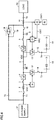
- Fig. 1 is a circuit block diagram showing a configuration of an uninterruptible power supply device in accordance with a first embodiment of the present invention.
- the uninterruptible power supply device is configured to once convert three-phase AC power supplied from an AC power supply 51 into DC power, reconvert the DC power into three-phase AC power, and supply the three-phase AC power to a load 52.
- Fig. 1 shows a circuit for only one phase for simplification of the drawings and description.
- the uninterruptible power supply device includes an input terminal T1, a bypass terminal T2, DC terminals T3 and T4, and an output terminal T5.
- Input terminal T1 is connected to AC power supply 51.
- AC power supply 51 may be a commercial AC power supply or a private power generator.
- AC power supply 51 supplies AC power having a commercial frequency, for example, to the uninterruptible power supply device.
- bypass terminal T2 is connected to a bypass AC power supply.
- the bypass AC power supply may be a commercial AC power supply or a private power generator.
- Fig. 1 shows a case where bypass terminal T2 is connected to AC power supply 51 together with input terminal T1.
- DC terminal T3 is connected to a storage battery 53.
- Storage battery 53 is charged when the AC power from AC power supply 51 is supplied normally, and is discharged when the AC power from AC power supply 51 is not supplied normally (for example, during power failure).
- DC terminal T4 is connected to a lithium ion battery 54. Lithium ion battery 54 is charged when load 52 is performing a regenerative operation, and is discharged when load 52 is performing a power running operation.
- Storage battery 53 has an advantage that it is inexpensive, but has a disadvantage that it is more degraded due to charge and discharge and cannot be charged and discharged many times.
- lithium ion battery 54 has a disadvantage that it is expensive, but has an advantage that it is less degraded due to charge and discharge and can be charged and discharged many times. Accordingly, since power failure does not occur often but a large amount of power is required in case of power failure, storage battery 53 is used as a battery for storing DC power used during power failure.
- Lithium ion battery 54 is used as a battery charged and discharged whenever the regenerative operation and the power running operation of load 52 are switched.
- Output terminal T5 is connected to load 52.
- Load 52 is a motor, for example, and is driven by the AC power supplied from the uninterruptible power supply device. In the first embodiment, it is assumed that the case where load 52 is performing the power running operation and the case where load 52 is performing the regenerative operation are alternately repeated.
- the uninterruptible power supply device includes switches 1, 10, 14, 15, and 19, a fuse 2, reactors 3 and 8, a converter 4, a DC bus 5, capacitors 6 and 9, an inverter 7, a current detector 11, bidirectional choppers 12 and 13, controllers 16 and 17, and a semiconductor switch 18.
- Switch 1, fuse 2, and reactor 3 are connected in series between input terminal T1 and an input terminal of converter 4.
- Switch 1 is turned on when the uninterruptible power supply device is used, and is turned off during maintenance of the uninterruptible power supply device, for example.
- Fuse 2 is blown when overcurrent flows to protect the uninterruptible power supply device.
- Reactor 3 enables the passage of an AC current from AC power supply 51 to converter 4, and disables the passage of a signal having a switching frequency generated by converter 4.
- Converter 4 receives the AC power supplied from AC power supply 51 via switch 1, fuse 2, and reactor 3. When the AC power from AC power supply 51 is supplied normally, converter 4 converts the AC power from AC power supply 51 into DC power, and outputs the DC power to DC bus 5. Even when a DC voltage VDC of DC bus 5 becomes higher than a rated voltage VR due to regenerative power generated by load 52, converter 4 does not return the regenerative power to the AC power supply 51 side. When the AC power from AC power supply 51 is not supplied normally (that is, during power failure), operation of converter 4 is stopped.
- DC bus 5 is connected between an output terminal of converter 4 and an input terminal of inverter 7 to transmit the DC power.
- Capacitor 6 is connected to DC bus 5 to stabilize DC voltage VDC of DC bus 5.
- Inverter 7 converts the DC power received from DC bus 5 into AC power having the commercial frequency, for example, and outputs the AC power to an output terminal.
- Reactor 8 is connected between the output terminal of inverter 7 and one terminal of switch 10.
- Capacitor 9 is connected to the one terminal of switch 10. The other terminal of switch 10 is connected to output terminal T5.
- Reactor 8 and capacitor 9 constitute a low pass filter, which enables the passage of the AC power having the commercial frequency, for example, generated by inverter 7, and disables the passage of a signal having the switching frequency generated by inverter 7.
- reactor 8 and capacitor 9 convert a rectangular wave-shaped AC voltage output from inverter 7 into a sinusoidal wave-shaped AC voltage.
- Switch 10 is turned on in an inverter power feeding mode in which the AC power from inverter 7 is supplied to load 52, and is turned off in a bypass power feeding mode in which the AC power supplied from AC power supply 51 via bypass terminal T2 is supplied to load 52.
- Current detector 11 detects an instantaneous value of an AC current flowing between the other terminal of switch 10 and output terminal T5, and outputs a signal indicating the detected value to controller 17.
- Bidirectional chopper 12 and switch 14 are connected in series between DC bus 5 and DC terminal T3. Switch 14 is turned on when the uninterruptible power supply device is used, and is turned off during maintenance of storage battery 53, for example. Bidirectional chopper 12 is controlled by controller 16, and transmits and receives DC power between DC bus 5 and storage battery 53.
- Controller 16 controls bidirectional chopper 12 based on an AC voltage VAC supplied from AC power supply 51. Controller 16 detects a voltage at a node between fuse 2 and reactor 3, for example, as AC voltage VAC.
- controller 16 controls bidirectional chopper 12 such that a DC current flows from DC bus 5 to storage battery 53, to charge storage battery 53.
- controller 16 controls bidirectional chopper 12 such that a DC current flows from storage battery 53 to DC bus 5, to discharge storage battery 53.
- Bidirectional chopper 13 and switch 15 are connected in series between DC bus 5 and DC terminal T4. Switch 15 is turned on when the uninterruptible power supply device is used, and is turned off during maintenance of lithium ion battery 54, for example. Bidirectional chopper 13 is controlled by controller 17, and transmits and receives DC power between DC bus 5 and lithium ion battery 54.
- Controller 17 controls bidirectional chopper 13 based on the output signal of current detector 11 and DC voltage VDC of DC bus 5. Controller 17 determines whether load 52 is performing the regenerative operation or the power running operation based on the output signal of current detector 11. Controller 17 performs three-phase to two-phase conversion (for example, dq conversion) on a three-phase AC current obtained from output signals of three current detectors 11, and obtains an active current and a reactive current.
- Controller 17 controls bidirectional chopper 13 based on the output signal of current detector 11 and DC voltage VDC of DC bus 5. Controller 17 determines whether load 52 is performing the regenerative operation or the power running operation based on the output signal of current detector 11. Controller 17 performs three-phase to two-phase conversion (for example, dq conversion) on a three-phase AC current obtained from output signals of three current detectors 11, and obtains an active current and a reactive current.
- controller 17 determines that load 52 is performing the power running operation, and when the active current has a negative value (that is, when the active current is flowing from load 52 to inverter 7), controller 17 determines that load 52 is performing the regenerative operation.
- controller 17 controls bidirectional chopper 13 such that a current flows from DC bus 5 to lithium ion battery 54, to charge lithium ion battery 54.
- Threshold voltage Vth is set to a voltage higher than rated voltage VR of DC voltage VDC by a predetermined voltage.
- controller 17 continues the charge of lithium ion battery 54 even when DC voltage VDC of DC bus 5 becomes lower than threshold voltage Vth.
- controller 17 controls bidirectional chopper 13 such that a DC current flows from lithium ion battery 54 to DC bus 5, to discharge lithium ion battery 54.
- DC voltage VDC of DC bus 5 can be reduced without supplying the regenerative power from load 52 to AC power supply 51. Therefore, an increase in DC voltage VDC of DC bus 5 can be suppressed even in a case where AC power supply 51 is a private power generator.
- the uninterruptible power supply device can have an improved efficiency. Furthermore, by discharging lithium ion battery 54, lithium ion battery 54 can be charged when load 52 subsequently performs the regenerative operation.
- Semiconductor switch 18 is connected between bypass terminal T2 and the other terminal of the switch 10, is turned on instantaneously when inverter 7 has a failure, and is turned off after a predetermined time.
- Switch 19 is connected in parallel with semiconductor switch 18, and is turned on when inverter 7 has a failure.
- semiconductor switch 18 is turned on instantaneously, switch 19 is turned on and switch 10 is turned off, and thereafter semiconductor switch 18 is turned off. Thereby, the AC power is supplied from AC power supply 51 to load 52 via switch 19, and operation of load 52 is continued.
- Switch 19 is turned on not only when inverter 7 has a failure but also in the bypass power feeding mode in which the AC power of AC power supply 51 is directly supplied to load 52.
- controller 16 controls bidirectional chopper 12 such that a current flows from DC bus 5 to storage battery 53, to charge storage battery 53.
- a voltage between terminals of storage battery 53 is set to a predetermined target voltage.
- controller 17 controls bidirectional chopper 13 such that a current flows from DC bus 5 to lithium ion battery 54, to charge lithium ion battery 54.
- controller 17 continues the charge of lithium ion battery 54 when load 52 is performing the regenerative operation, even when DC voltage VDC of DC bus 5 is lower than threshold voltage Vth.
- controller 17 controls bidirectional chopper 13 such that a DC current flows from lithium ion battery 54 to DC bus 5, to discharge lithium ion battery 54.
- DC power supplied from lithium ion battery 54 to DC bus 5 is converted into AC power by inverter 7, and is supplied to load 52.
- inverter 7 When inverter 7 has a failure, semiconductor switch 18 is turned on instantaneously, and the AC power from AC power supply 51 is supplied to load 52 via semiconductor switch 18. Switch 10 is turned off and switch 19 is turned on, and thereafter semiconductor switch 18 is turned off. Thereby, the AC power from AC power supply 51 is supplied to load 52 via switch 19, and operation of load 52 is continued.
- controller 16 controls bidirectional chopper 12 such that a current flows from storage battery 53 to DC bus 5, to discharge storage battery 53.
- DC power supplied from storage battery 53 to DC bus 5 is converted into AC power by inverter 7, and is supplied to load 52. Therefore, operation of load 52 can be continued as long as the DC power is stored in storage battery 53.
- Controller 17 operates as in the case where AC voltage VAC from AC power supply 51 is normal, and causes lithium ion battery 54 to be charged when load 52 is performing the regenerative operation, and causes lithium ion battery 54 to be discharged when load 52 is performing the power running operation.
- DC bus 5 is connected to lithium ion battery 54 via bidirectional chopper 13, lithium ion battery 54 is charged when load 52 is performing the regenerative operation, and lithium ion battery 54 is discharged when the load is performing the power running operation. Therefore, an increase in DC voltage VDC of DC bus 5 can be suppressed without returning the regenerative power generated by load 52 to AC power supply 51. In addition, since the regenerative power generated by load 52 can be utilized effectively, the uninterruptible power supply device can have an improved efficiency.
- an electric double layer capacitor may be provided, or an electrolytic capacitor may be provided.
- a load configured not to perform a regenerative operation is often connected to an uninterruptible power supply device, and a load configured to perform a regenerative operation is not often connected thereto. If a load configured not to perform a regenerative operation is connected to an uninterruptible power supply device, bidirectional chopper 13 and lithium ion battery 54 are not used in the uninterruptible power supply device in the first embodiment, and thus they become useless. A solution to this problem is sought in a second embodiment.
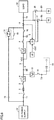
- Fig. 2 is a circuit block diagram showing a configuration of an uninterruptible power supply device in accordance with a second embodiment of the present invention, which is compared with Fig. 1 .
- this uninterruptible power supply device is different from the uninterruptible power supply device in Fig. 1 in that a monitoring unit 20 and a controller 21 are provided instead of controller 17.
- Monitoring unit 20 determines whether load 52 is performing a regenerative operation or a power running operation based on the output signal of current detector 11, and sets a control signal CNT to an "L" level when the regenerative operation of load 52 is performed within a predetermined time. Monitoring unit 20 sets control signal CNT to an "H" level when the regenerative operation of load 52 is not performed even after the lapse of the predetermined time. This is because, if the regenerative operation of load 52 is not performed even after the lapse of the predetermined time, it is estimated that load 52 configured to perform a power running operation only is connected.
- controller 21 When control signal CNT is at an "L" level, controller 21 operates as with controller 17 in the first embodiment (that is, performs a first mode). Controller 21 controls bidirectional chopper 13 based on the output signal of current detector 11 and DC voltage VDC of DC bus 5. Controller 21 determines whether load 52 is performing the regenerative operation or the power running operation based on the output signal of current detector 11.
- controller 21 controls bidirectional chopper 13 such that a current flows from DC bus 5 to lithium ion battery 54, to charge lithium ion battery 54. In a case where charge of lithium ion battery 54 is started, controller 21 continues the charge of lithium ion battery 54 even when DC voltage VDC of DC bus 5 becomes lower than threshold voltage Vth.
- controller 21 controls bidirectional chopper 13 such that a DC current flows from lithium ion battery 54 to DC bus 5, to discharge lithium ion battery 54.
- controller 21 When control signal CNT is at an "H" level, controller 21 operates as with controller 16 (that is, performs a second mode). Controller 21 controls bidirectional chopper 13 based on AC voltage VAC supplied from AC power supply 51. When AC voltage VAC is normal (that is, when the AC power is supplied normally from AC power supply 51), controller 21 controls bidirectional chopper 13 such that a DC current flows from DC bus 5 to lithium ion battery 54, to charge lithium ion battery 54.
- controller 21 controls bidirectional chopper 13 such that a DC current flows from lithium ion battery 54 to DC bus 5, to discharge lithium ion battery 54. Since other configurations and operations are the same as those in the first embodiment, the description thereof will not be repeated.
- bidirectional chopper 13 and lithium ion battery 54 can be used effectively, and the amount of power which can be supplied in case of power failure can be increased.
- whether load 52 is performing the regenerative operation or the power running operation is determined based on a detection result of current detector 11, and when a time for which load 52 is not performing the regenerative operation exceeds the predetermined time, lithium ion battery 54 is used as a battery for supplying power during power failure.
- lithium ion battery 54 is used as a battery for supplying power during power failure.
- Fig. 3 is a circuit block diagram showing a configuration of an uninterruptible power supply device in accordance with a third embodiment of the present invention, which is compared with Fig. 2 .
- this uninterruptible power supply device is different from the uninterruptible power supply device in Fig. 2 in that monitoring unit 20 is replaced with a setting unit 22.
- Setting unit 22 includes a button or the like to be operated by a user of the uninterruptible power supply device, and is used to set whether or not load 52 is the one configured to perform the regenerative operation. When it is set by the user that load 52 is the one configured to perform the regenerative operation, setting unit 22 sets control signal CNT to an "L" level. When it is set by the user that load 52 is the one configured not to perform the regenerative operation, setting unit 22 sets control signal CNT to an "H" level. Setting unit 22 constitutes a selector configured to select any one mode of the first mode and the second mode.
- Controller 21 is the same as the one shown in Fig. 2 , and controls bidirectional chopper 13 based on control signal CNT and AC voltage VAC. Since other configurations and operations are the same as those in the second embodiment, the description thereof will not be repeated.
- cost reduction can be achieved when compared with the second embodiment.
- Fig. 4 is a circuit block diagram showing a configuration of an uninterruptible power supply device in accordance with a fourth embodiment of the present invention, which is compared with Fig. 3 .
- this uninterruptible power supply device is different from the uninterruptible power supply device in Fig. 3 in that a monitoring unit 23 is added.
- setting unit 22 sets a control signal CNT1 to an "L" level.
- control signal CNT1 from setting unit 22 is at an "L” level
- monitoring unit 23 operates as with monitoring unit 20 in Fig. 2 .
- Monitoring unit 23 sets control signal CNT to an "L” level when the regenerative operation of load 52 is performed within a predetermined time, and sets control signal CNT to an "H” level when the regenerative operation of load 52 is not performed even after the lapse of the predetermined time.
- monitoring unit 23 sets control signal CNT to an "H” level. Even in a case where control signal CNT1 from setting unit 22 is at an "H” level, monitoring unit 23 operates as with monitoring unit 20 in Fig. 2 when the regenerative operation of load 52 is performed, and sets control signal CNT to an "L” level when the regenerative operation of load 52 is performed within a predetermined time. Monitoring unit 23 sets control signal CNT to an "H” level when the regenerative operation of load 52 is not performed even after the lapse of the predetermined time. Since other configurations and operations are the same as those in the second and third embodiments, the description thereof will not be repeated.
- controller 21 can be switched without operating setting unit 22. Therefore, even in a case where the user forgets to operate setting unit 22 when the user changes the one load to the other load, operation of controller 21 can be automatically switched.
- Fig. 5 is a circuit block diagram showing a configuration of an uninterruptible power supply device in accordance with a first example, which is compared with Fig. 3 .
- this uninterruptible power supply device is different from the uninterruptible power supply device in Fig. 3 in that a controller 30, a switch 31, and a load terminal T6 are provided instead of bidirectional chopper 13, switch 15, DC terminal T4, and controller 21.
- Switch 31 is connected between output terminal T5 and load terminal T6, and is controlled by controller 30.
- a load 55 for consuming the regenerative power generated by load 52 is connected to load terminal T6.
- Load 55 is, for example, a resistive element, an inductor, or the like.
- Setting unit 22 is the same as the one shown in Fig. 3 .
- load 52 is the one configured to perform the regenerative operation
- setting unit 22 sets control signal CNT to an "L" level.
- load 52 is the one configured not to perform the regenerative operation
- setting unit 22 sets control signal CNT to an "H" level.
- controller 30 controls switch 31 based on the output signal of current detector 11 and DC voltage VDC of DC bus 5. Controller 30 determines whether load 52 is performing the regenerative operation or the power running operation based on the output signal of current detector 11.
- controller 30 When load 52 is performing the regenerative operation and DC voltage VDC of DC bus 5 exceeds threshold voltage Vth, controller 30 turns on switch 31. Thereby, at least a portion of the regenerative power generated by load 52 is supplied to load 55 via switch 31, and is consumed by load 55. When controller 30 turns on switch 31, controller 30 keeps switch 31 ON even when DC voltage VDC of DC bus 5 becomes lower than threshold voltage Vth.
- controller 30 When load 52 is performing the power running operation, controller 30 turns off switch 31. When control signal CNT is at an "H” level, controller 30 sets switch 31 to an OFF state. Even in a case where control signal CNT is at an "H” level, controller 30 turns on switch 31 when load 52 is performing the regenerative operation. Since other configurations and operations are the same as those in the first embodiment, the description thereof will not be repeated.
- switch 31 is connected between output terminal T5 to which load 52 is connected and load terminal T6 to which load 55 for consuming the regenerative power generated by load 52 is connected, switch 31 is turned on when load 52 is performing the regenerative operation, and switch 31 is turned off when load 52 is performing the power running operation. Therefore, an increase in DC voltage VDC of DC bus 5 can be suppressed without returning the regenerative power generated by load 52 to AC power supply 51.
- Fig. 6 is a circuit block diagram showing a configuration of an uninterruptible power supply device in accordance with a second example, which is compared with Fig. 5 .
- this uninterruptible power supply device is different from the uninterruptible power supply device in Fig. 5 in that controller 30 is replaced with a controller 33, and a switch 32 and a load terminal T7 are added.
- Switch 32 is connected between output terminal T5 and load terminal T7, and is controlled by controller 33.
- a load 56 for consuming the regenerative power generated by load 52 is connected to load terminal T7.
- Load 56 is, for example, a resistive element, an inductor, or the like.
- controller 33 controls switches 31 and 32 based on the output signal of current detector 11 and DC voltage VDC of DC bus 5. Controller 33 obtains an active current flowing to load 52 based on output signals of three current detectors 11. When the active current has a negative value (that is, when the active current is flowing from load 52), controller 33 determines that load 52 is performing the regenerative operation, and when the active current has a positive value (that is, when the active current is flowing into load 52), controller 33 determines that load 52 is performing the power running operation.
- controller 33 When load 52 is performing the regenerative operation and DC voltage VDC of DC bus 5 exceeds threshold voltage Vth, controller 33 turns on only switch 31 of switches 31 and 32 if an absolute value of the active current is smaller than a threshold current, and turns on both switches 31 and 32 if the absolute value of the active current is larger than the threshold current. Thereby, when a regenerative current generated by load 52 is relatively small, the regenerative current can be consumed by load 55 only, and when the regenerative current generated by load 52 is relatively large, the regenerative current can be consumed by loads 55 and 56. Since other configurations and operations are the same as those in the first example the description thereof will not be repeated.
- a set of switch 31 and load 55 and a set of switch 32 and load 56 are provided in the second example, the present invention is not limited thereto, and three or more sets of one switch and one load may be provided to change the number of switches to be turned on depending on the magnitude of the regenerative current generated by load 52.
- T1 input terminal; T2: bypass terminal; T3, T4: DC terminal; T5: output terminal; T6, T7: load terminal; 1, 10, 14, 15, 19, 31, 32: switch; 2: fuse; 3, 8: reactor; 4: converter; 5: DC bus; 6, 9: capacitor; 7: inverter; 11: current detector; 12, 13: bidirectional chopper; 16, 17, 21, 30, 33: controller; 18: semiconductor switch; 20, 23: monitoring unit; 22: setting unit; 51: AC power supply; 52, 55, 56: load; 53: storage battery; 54: lithium ion battery.
Landscapes
- Engineering & Computer Science (AREA)
- Power Engineering (AREA)
- Business, Economics & Management (AREA)
- Emergency Management (AREA)
- Stand-By Power Supply Arrangements (AREA)
- Inverter Devices (AREA)
- Charge And Discharge Circuits For Batteries Or The Like (AREA)
Claims (7)
- Dispositif d'alimentation en énergie non interruptible comprenant :un convertisseur (4) configuré pour convertir de l'énergie à courant alternatif provenant d'une alimentation en courant alternatif (51) en énergie à courant continu et pour délivrer l'énergie à courant continu à un bus à courant continu (5) ;un onduleur (7) configuré pour convertir l'énergie à courant continu reçue du bus à courant continu en énergie à courant alternatif et délivrer l'énergie à courant alternatif à une charge (52) ;un premier hacheur bidirectionnel (12) configuré pour transmettre et recevoir de l'énergie à courant continu entre le bus à courant continu et un premier dispositif de stockage d'énergie (53) ;un deuxième hacheur bidirectionnel (13) configuré pour transmettre et recevoir de l'énergie à courant continu entre le bus à courant continu et un deuxième dispositif de stockage d'énergie (54) ;un premier circuit de commande (16) configuré pour commander le premier hacheur bidirectionnel de telle sorte qu'un courant circule depuis le bus à courant continu jusqu'au premier dispositif de stockage d'énergie quand l'énergie à courant alternatif est délivrée normalement par l'alimentation à courant alternatif, et commander le premier hacheur bidirectionnel de telle sorte qu'un courant circule depuis le premier dispositif de stockage d'énergie jusqu'au bus à courant continu quand l'énergie à courant alternatif n'est pas délivrée normalement par l'alimentation à courant alternatif ; etun deuxième circuit de commande (21) configuré pour réaliser un premier mode,dans le premier mode, le deuxième circuit de commande étant configuré pour commander le deuxième hacheur bidirectionnel de telle sorte qu'un courant circule depuis le bus à courant continu jusqu'au deuxième dispositif de stockage d'énergie quand la charge réalise une opération de régénération, et commander le deuxième hacheur bidirectionnel de telle sorte qu'un courant circule depuis le deuxième dispositif de stockage d'énergie jusqu'au bus à courant continu quand la charge réalise une opération de fonctionnement de puissance, caractérisé en ce quele deuxième circuit de commande est configuré pour réaliser le premier mode quand un temps pendant lequel la charge ne réalise pas l'opération de régénération est plus court qu'un temps prédéterminé, et commuter du premier mode à un deuxième mode quand l'opération de régénération de la charge n'est pas réalisée même après l'écoulement du temps prédéterminé, indiquant que la charge connectée n'est pas configurée pour réaliser une opération de régénération ;dans le deuxième mode, le deuxième circuit de commande est configuré pour commander le deuxième hacheur bidirectionnel de telle sorte qu'un courant circule depuis le bus à courant continu jusqu'au deuxième dispositif de stockage d'énergie quand l'énergie à courant alternatif est délivrée normalement par l'alimentation à courant alternatif, et commander le deuxième hacheur bidirectionnel de telle sorte qu'un courant circule depuis le deuxième dispositif de stockage d'énergie jusqu'au bus à courant continu quand l'énergie à courant alternatif n'est pas délivrée normalement par l'alimentation à courant alternatif.
- Dispositif d'alimentation en énergie non interruptible selon la revendication 1, comprenant en outre un détecteur de courant (11) configuré pour détecter un courant qui circule entre l'onduleur et la charge,
le deuxième circuit de commande étant configuré pour déterminer si la charge réalise l'opération de régénération ou l'opération de fonctionnement de puissance sur la base d'un résultat de détection du détecteur de courant, et commander le deuxième hacheur bidirectionnel sur la base d'un résultat de détermination. - Dispositif d'alimentation en énergie non interruptible selon la revendication 2, dans lequel l'onduleur est configuré pour convertir l'énergie à courant continu reçue du bus à courant continu en énergie à courant alternatif triphasé et délivrer l'énergie à courant alternatif triphasé à la charge,
le détecteur de courant est configuré pour détecter un courant alternatif triphasé qui circule entre l'onduleur et la charge, et
le deuxième circuit de commande est configuré pour réaliser une conversion triphasée à biphasée sur le courant alternatif triphasé détecté par le détecteur de courant et obtenir un courant actif et un courant réactif, déterminer que la charge réalise l'opération de fonctionnement de puissance quand le courant actif circule depuis l'onduleur jusqu'à la charge, et déterminer que la charge réalise l'opération de régénération quand le courant actif circule depuis la charge jusqu'à l'onduleur. - Dispositif d'alimentation en énergie non interruptible selon la revendication 1, dans lequel le deuxième circuit de commande est configuré pour commencer à commander le deuxième hacheur bidirectionnel de telle sorte que le courant circule depuis le bus à courant continu jusqu'au deuxième dispositif de stockage d'énergie quand la charge réalise l'opération de régénération et une tension du bus à courant continu dépasse une tension de seuil prédéterminée, et
une fois que le deuxième circuit de commande commence à commander le deuxième hacheur bidirectionnel, le deuxième circuit de commande est configuré pour continuer à commander le deuxième hacheur bidirectionnel de telle sorte que le courant circule depuis le bus à courant continu jusqu'au deuxième dispositif de stockage d'énergie quand la charge réalise l'opération de régénération, même lorsque la tension du bus à courant continu est inférieure à la tension de seuil prédéterminée. - Dispositif d'alimentation en énergie non interruptible selon la revendication 1, dans lequel le deuxième dispositif de stockage d'énergie est une batterie lithium ion.
- Dispositif d'alimentation en énergie non interruptible selon la revendication 1, dans lequel le deuxième dispositif de stockage d'énergie est un condensateur à double couche électrique.
- Dispositif d'alimentation en énergie non interruptible selon la revendication 1, dans lequel le deuxième dispositif de stockage d'énergie est un condensateur électrolytique.
Applications Claiming Priority (1)
| Application Number | Priority Date | Filing Date | Title |
|---|---|---|---|
| PCT/JP2016/061968 WO2017179162A1 (fr) | 2016-04-14 | 2016-04-14 | Dispositif de source d'alimentation sans interruption |
Publications (4)
| Publication Number | Publication Date |
|---|---|
| EP3444922A1 EP3444922A1 (fr) | 2019-02-20 |
| EP3444922A4 EP3444922A4 (fr) | 2019-12-18 |
| EP3444922B1 true EP3444922B1 (fr) | 2021-01-13 |
| EP3444922B8 EP3444922B8 (fr) | 2021-03-17 |
Family
ID=60042811
Family Applications (1)
| Application Number | Title | Priority Date | Filing Date |
|---|---|---|---|
| EP16898622.2A Active EP3444922B8 (fr) | 2016-04-14 | 2016-04-14 | Dispositif de source d'alimentation sans interruption |
Country Status (6)
| Country | Link |
|---|---|
| US (1) | US10811898B2 (fr) |
| EP (1) | EP3444922B8 (fr) |
| JP (1) | JP6725647B2 (fr) |
| KR (1) | KR102193826B1 (fr) |
| CN (1) | CN109075599B (fr) |
| WO (1) | WO2017179162A1 (fr) |
Families Citing this family (19)
| Publication number | Priority date | Publication date | Assignee | Title |
|---|---|---|---|---|
| JP6608405B2 (ja) * | 2017-07-19 | 2019-11-20 | 矢崎総業株式会社 | 電圧変換ユニット |
| JP6958287B2 (ja) | 2017-11-24 | 2021-11-02 | トヨタ自動車株式会社 | 電力制御システムおよび車両 |
| US10790670B1 (en) * | 2018-03-08 | 2020-09-29 | Zerobase Energy, Llc | Hybrid generator system and method with multi tasked power inverter |
| JP6957416B2 (ja) * | 2018-06-28 | 2021-11-02 | 東芝三菱電機産業システム株式会社 | 無停電電源システム |
| US11296545B2 (en) | 2018-07-04 | 2022-04-05 | Toshiba Mitsubishi-Electric Industrial Systems Corporation | Uninterruptible power supply device |
| KR102566567B1 (ko) * | 2018-08-03 | 2023-08-11 | 도시바 미쓰비시덴키 산교시스템 가부시키가이샤 | 무정전 전원 장치 |
| WO2020100225A1 (fr) * | 2018-11-14 | 2020-05-22 | 東芝三菱電機産業システム株式会社 | Dispositif de conversion de courant |
| JP6571903B1 (ja) * | 2018-11-20 | 2019-09-04 | 東芝三菱電機産業システム株式会社 | 無停電電源装置 |
| EP3672023B1 (fr) * | 2018-12-17 | 2021-09-01 | ABB Schweiz AG | Dispositif d'alimentation sans coupure (ups) pour installations de distribution d'énergie électrique |
| US20200266652A1 (en) * | 2019-02-20 | 2020-08-20 | Hamilton Sundstrand Corporation | Electrical power system including an active rectifier |
| JP7140711B2 (ja) * | 2019-05-20 | 2022-09-21 | 東芝三菱電機産業システム株式会社 | 無停電電源システム |
| WO2020261366A1 (fr) | 2019-06-25 | 2020-12-30 | 東芝三菱電機産業システム株式会社 | Dispositif d'alimentation sans interruption |
| US11888340B2 (en) * | 2020-12-04 | 2024-01-30 | Schneider Electric It Corporation | Method to enhance the life of a lithium battery |
| KR102343175B1 (ko) * | 2021-09-13 | 2021-12-24 | 이화전기공업 주식회사 | 직류 부하에 지속적으로 전력 공급이 가능한 무정전 전원장치 |
| JP7792867B2 (ja) * | 2022-06-10 | 2025-12-26 | 三菱電機株式会社 | 無停電電源装置 |
| CN118715696A (zh) | 2022-11-16 | 2024-09-27 | 株式会社Tmeic | 不间断电源装置 |
| US20250038554A1 (en) * | 2023-07-26 | 2025-01-30 | Robert Bosch Gmbh | Power equipment with hybrid power supply |
| US12580412B2 (en) * | 2023-08-01 | 2026-03-17 | Schneider Electric It Corporation | High efficiency line VFI UPS invention |
| JP7830772B1 (ja) * | 2025-03-19 | 2026-03-16 | 株式会社Tmeic | 無停電電源装置 |
Family Cites Families (37)
| Publication number | Priority date | Publication date | Assignee | Title |
|---|---|---|---|---|
| JPH0564378A (ja) | 1990-11-20 | 1993-03-12 | Mitsubishi Electric Corp | 無停電電源装置 |
| JPH11299275A (ja) * | 1998-04-14 | 1999-10-29 | Osaka Gas Co Ltd | エレベータの電源装置 |
| JP4283963B2 (ja) * | 2000-02-28 | 2009-06-24 | 三菱電機株式会社 | エレベータの制御装置 |
| JP4249364B2 (ja) * | 2000-02-28 | 2009-04-02 | 三菱電機株式会社 | エレベータの制御装置 |
| JP4347982B2 (ja) * | 2000-02-28 | 2009-10-21 | 三菱電機株式会社 | エレベーターの制御装置 |
| US20060164044A1 (en) * | 2005-01-25 | 2006-07-27 | Keat Cheong S | Digital pulse controlled capacitor charging circuit |
| JP2009525238A (ja) * | 2006-01-30 | 2009-07-09 | オーチス エレベータ カンパニー | 容量式エネルギ保存デバイスを含むエレベータ駆動アセンブリ |
| JP5420140B2 (ja) * | 2006-02-27 | 2014-02-19 | 東芝エレベータ株式会社 | エレベータ制御装置 |
| KR20090113241A (ko) * | 2006-06-28 | 2009-10-29 | 가부시키가이샤 야스카와덴키 | 인버터 제어 장치 및 그 운전 방법 |
| JP5089365B2 (ja) * | 2007-12-17 | 2012-12-05 | 三菱電機株式会社 | エレベータ蓄電制御装置 |
| WO2010019126A1 (fr) * | 2008-08-15 | 2010-02-18 | Otis Elevator Company | Gestion de puissance provenant de multiples sources dans un système de puissance d’ascenseur |
| WO2010044164A1 (fr) * | 2008-10-16 | 2010-04-22 | 東芝三菱電機産業システム株式会社 | Convertisseur de puissance |
| ES2943547T3 (es) * | 2008-11-17 | 2023-06-14 | Otis Elevator Co | Calibración del estado de carga de la batería |
| EP2358623B1 (fr) * | 2008-11-21 | 2016-05-04 | Otis Elevator Company | Fonctionnement d'un entraînement régénératif triphasé à partir de sources d'alimentation en courant continu et en courant alternatif monophasé mélangées |
| TWI364900B (en) * | 2008-12-01 | 2012-05-21 | Delta Electronics Inc | Uninterruptible power supply |
| JP5471128B2 (ja) * | 2009-07-31 | 2014-04-16 | 富士電機株式会社 | 電力変換装置 |
| US9236769B2 (en) * | 2009-09-11 | 2016-01-12 | Toshiba Mitsubishi-Electric Industrial Systems Corporation | Control device |
| JP5640387B2 (ja) * | 2010-01-21 | 2014-12-17 | 日本電気株式会社 | 電源装置 |
| JP5561071B2 (ja) | 2010-09-29 | 2014-07-30 | サンケン電気株式会社 | 無停電電源装置 |
| US8830701B2 (en) * | 2011-06-13 | 2014-09-09 | Tdk Corporation | DC-DC converter |
| JP5843624B2 (ja) | 2012-01-17 | 2016-01-13 | 三菱電機株式会社 | 系統連系用電力変換システム |
| JP5559261B2 (ja) * | 2012-07-17 | 2014-07-23 | ファナック株式会社 | 蓄電装置を有するモータ駆動装置 |
| JP5812976B2 (ja) | 2012-12-07 | 2015-11-17 | 東芝エレベータ株式会社 | 昇降機を備えた建物の電力システム |
| JP5602890B2 (ja) * | 2013-01-29 | 2014-10-08 | ファナック株式会社 | 蓄電装置および抵抗放電装置を有するモータ制御装置 |
| US20160016483A1 (en) * | 2013-04-03 | 2016-01-21 | Autonetworks Technologies, Ltd. | Control apparatus, power supply control apparatus, charge control method, charge control apparatus, and power supply apparatus for vehicles |
| KR102314037B1 (ko) * | 2014-06-09 | 2021-10-15 | 엘지전자 주식회사 | 모터 구동장치 및 이를 구비하는 공기조화기 |
| WO2015194013A1 (fr) * | 2014-06-19 | 2015-12-23 | 三菱電機株式会社 | Système d'entraînement de moteur à courant alternatif (ca) |
| JP6294187B2 (ja) * | 2014-08-22 | 2018-03-14 | 株式会社日立製作所 | 無停電電源装置 |
| US10245959B2 (en) * | 2014-10-07 | 2019-04-02 | Nanyang Technological University | Power converter system and method of manufacturing thereof |
| WO2016084179A1 (fr) * | 2014-11-27 | 2016-06-02 | 東芝三菱電機産業システム株式会社 | Alimentation électrique sans coupure |
| KR102284483B1 (ko) * | 2014-12-02 | 2021-08-02 | 삼성에스디아이 주식회사 | 배터리 모듈 및 그의 구동방법 |
| CN108141140B (zh) * | 2015-09-30 | 2020-10-30 | 东芝三菱电机产业系统株式会社 | 不间断电源装置 |
| US9893562B2 (en) * | 2015-11-23 | 2018-02-13 | Jae Jin Lee | Direct current uninterruptible power supply system |
| US10756567B2 (en) * | 2015-11-27 | 2020-08-25 | Toshiba Mitsubishi-Electric Industrial Systems Corporation | Uninterruptible power supply device |
| US10211670B2 (en) * | 2015-12-22 | 2019-02-19 | Schneider Electric It Corporation | UPS with integrated bypass switch |
| US20170256957A1 (en) * | 2016-03-04 | 2017-09-07 | G4 Synergetics, Inc. | Hybrid power delivery with improved power control |
| WO2017179186A1 (fr) * | 2016-04-15 | 2017-10-19 | 東芝三菱電機産業システム株式会社 | Dispositif source d'alimentation sans coupure |
-
2016
- 2016-04-14 CN CN201680084543.3A patent/CN109075599B/zh active Active
- 2016-04-14 WO PCT/JP2016/061968 patent/WO2017179162A1/fr not_active Ceased
- 2016-04-14 EP EP16898622.2A patent/EP3444922B8/fr active Active
- 2016-04-14 KR KR1020187031684A patent/KR102193826B1/ko active Active
- 2016-04-14 US US16/093,023 patent/US10811898B2/en active Active
- 2016-04-14 JP JP2018511828A patent/JP6725647B2/ja active Active
Non-Patent Citations (1)
| Title |
|---|
| None * |
Also Published As
| Publication number | Publication date |
|---|---|
| EP3444922A4 (fr) | 2019-12-18 |
| JP6725647B2 (ja) | 2020-07-22 |
| JPWO2017179162A1 (ja) | 2019-01-31 |
| CN109075599A (zh) | 2018-12-21 |
| EP3444922B8 (fr) | 2021-03-17 |
| EP3444922A1 (fr) | 2019-02-20 |
| CN109075599B (zh) | 2021-12-07 |
| US10811898B2 (en) | 2020-10-20 |
| US20190181677A1 (en) | 2019-06-13 |
| KR102193826B1 (ko) | 2020-12-22 |
| WO2017179162A1 (fr) | 2017-10-19 |
| KR20180129894A (ko) | 2018-12-05 |
Similar Documents
| Publication | Publication Date | Title |
|---|---|---|
| US10811898B2 (en) | Uninterruptible power supply device | |
| US10784713B2 (en) | Uninterruptible power supply device | |
| US9093861B2 (en) | Power conversion system and uninterruptible power supply system | |
| WO2013088799A1 (fr) | Système d'alimentation en courant et conditionneur de courant destiné à une charge et à une décharge | |
| JP5561071B2 (ja) | 無停電電源装置 | |
| JP6099719B1 (ja) | 直流給電システム | |
| JP2012175864A (ja) | 蓄電システム | |
| JP6306778B2 (ja) | 電気エネルギー蓄積装置 | |
| CN109196761B (zh) | 电源系统 | |
| US11271419B2 (en) | Uninterruptible power supply device | |
| CN112438008A (zh) | 不间断电源装置 | |
| JP6468593B2 (ja) | 蓄電システム | |
| JP2017011910A (ja) | 無停電電源装置 | |
| JP5819783B2 (ja) | 無停電電源システム | |
| JP5667915B2 (ja) | 直流電源装置 | |
| KR20180132869A (ko) | 무정전 전원 장치 | |
| KR102209827B1 (ko) | 에너지 저장 장치 | |
| EP3275720B1 (fr) | Dispositif d'alimentation électrique auxiliaire | |
| JP5879510B2 (ja) | 蓄電システム | |
| WO2022244643A1 (fr) | Dispositif d'alimentation électrique | |
| JP2012125083A (ja) | 交流モータ駆動装置 | |
| JP2015192513A (ja) | 電源装置、及びその制御方法 | |
| KR20170121647A (ko) | 에너지 저장 시스템 |
Legal Events
| Date | Code | Title | Description |
|---|---|---|---|
| STAA | Information on the status of an ep patent application or granted ep patent |
Free format text: STATUS: THE INTERNATIONAL PUBLICATION HAS BEEN MADE |
|
| PUAI | Public reference made under article 153(3) epc to a published international application that has entered the european phase |
Free format text: ORIGINAL CODE: 0009012 |
|
| STAA | Information on the status of an ep patent application or granted ep patent |
Free format text: STATUS: REQUEST FOR EXAMINATION WAS MADE |
|
| 17P | Request for examination filed |
Effective date: 20181023 |
|
| AK | Designated contracting states |
Kind code of ref document: A1 Designated state(s): AL AT BE BG CH CY CZ DE DK EE ES FI FR GB GR HR HU IE IS IT LI LT LU LV MC MK MT NL NO PL PT RO RS SE SI SK SM TR |
|
| AX | Request for extension of the european patent |
Extension state: BA ME |
|
| DAV | Request for validation of the european patent (deleted) | ||
| DAX | Request for extension of the european patent (deleted) | ||
| RIC1 | Information provided on ipc code assigned before grant |
Ipc: H02J 9/06 20060101ALI20190806BHEP Ipc: H02J 7/34 20060101AFI20190806BHEP |
|
| A4 | Supplementary search report drawn up and despatched |
Effective date: 20191115 |
|
| RIC1 | Information provided on ipc code assigned before grant |
Ipc: H02J 9/06 20060101ALI20191111BHEP Ipc: H02J 7/34 20060101AFI20191111BHEP |
|
| GRAP | Despatch of communication of intention to grant a patent |
Free format text: ORIGINAL CODE: EPIDOSNIGR1 |
|
| STAA | Information on the status of an ep patent application or granted ep patent |
Free format text: STATUS: GRANT OF PATENT IS INTENDED |
|
| INTG | Intention to grant announced |
Effective date: 20200730 |
|
| GRAS | Grant fee paid |
Free format text: ORIGINAL CODE: EPIDOSNIGR3 |
|
| GRAA | (expected) grant |
Free format text: ORIGINAL CODE: 0009210 |
|
| STAA | Information on the status of an ep patent application or granted ep patent |
Free format text: STATUS: THE PATENT HAS BEEN GRANTED |
|
| GRAT | Correction requested after decision to grant or after decision to maintain patent in amended form |
Free format text: ORIGINAL CODE: EPIDOSNCDEC |
|
| AK | Designated contracting states |
Kind code of ref document: B1 Designated state(s): AL AT BE BG CH CY CZ DE DK EE ES FI FR GB GR HR HU IE IS IT LI LT LU LV MC MK MT NL NO PL PT RO RS SE SI SK SM TR |
|
| RAP1 | Party data changed (applicant data changed or rights of an application transferred) |
Owner name: TOSHIBA MITSUBISHI-ELECTRIC INDUSTRIAL SYSTEMS CORPORATION |
|
| REG | Reference to a national code |
Ref country code: GB Ref legal event code: FG4D |
|
| RIN1 | Information on inventor provided before grant (corrected) |
Inventor name: TOYODA, MASARU |
|
| REG | Reference to a national code |
Ref country code: CH Ref legal event code: EP |
|
| RAP2 | Party data changed (patent owner data changed or rights of a patent transferred) |
Owner name: TOSHIBA MITSUBISHI-ELECTRIC INDUSTRIAL SYSTEMS CORPORATION |
|
| REG | Reference to a national code |
Ref country code: DE Ref legal event code: R096 Ref document number: 602016051552 Country of ref document: DE |
|
| REG | Reference to a national code |
Ref country code: IE Ref legal event code: FG4D |
|
| REG | Reference to a national code |
Ref country code: AT Ref legal event code: REF Ref document number: 1355275 Country of ref document: AT Kind code of ref document: T Effective date: 20210215 |
|
| REG | Reference to a national code |
Ref country code: CH Ref legal event code: PK Free format text: BERICHTIGUNG B8 |
|
| REG | Reference to a national code |
Ref country code: AT Ref legal event code: MK05 Ref document number: 1355275 Country of ref document: AT Kind code of ref document: T Effective date: 20210113 |
|
| REG | Reference to a national code |
Ref country code: NL Ref legal event code: MP Effective date: 20210113 |
|
| REG | Reference to a national code |
Ref country code: LT Ref legal event code: MG9D |
|
| PG25 | Lapsed in a contracting state [announced via postgrant information from national office to epo] |
Ref country code: NO Free format text: LAPSE BECAUSE OF FAILURE TO SUBMIT A TRANSLATION OF THE DESCRIPTION OR TO PAY THE FEE WITHIN THE PRESCRIBED TIME-LIMIT Effective date: 20210413 Ref country code: PT Free format text: LAPSE BECAUSE OF FAILURE TO SUBMIT A TRANSLATION OF THE DESCRIPTION OR TO PAY THE FEE WITHIN THE PRESCRIBED TIME-LIMIT Effective date: 20210513 Ref country code: FI Free format text: LAPSE BECAUSE OF FAILURE TO SUBMIT A TRANSLATION OF THE DESCRIPTION OR TO PAY THE FEE WITHIN THE PRESCRIBED TIME-LIMIT Effective date: 20210113 Ref country code: GR Free format text: LAPSE BECAUSE OF FAILURE TO SUBMIT A TRANSLATION OF THE DESCRIPTION OR TO PAY THE FEE WITHIN THE PRESCRIBED TIME-LIMIT Effective date: 20210414 Ref country code: HR Free format text: LAPSE BECAUSE OF FAILURE TO SUBMIT A TRANSLATION OF THE DESCRIPTION OR TO PAY THE FEE WITHIN THE PRESCRIBED TIME-LIMIT Effective date: 20210113 Ref country code: LT Free format text: LAPSE BECAUSE OF FAILURE TO SUBMIT A TRANSLATION OF THE DESCRIPTION OR TO PAY THE FEE WITHIN THE PRESCRIBED TIME-LIMIT Effective date: 20210113 Ref country code: BG Free format text: LAPSE BECAUSE OF FAILURE TO SUBMIT A TRANSLATION OF THE DESCRIPTION OR TO PAY THE FEE WITHIN THE PRESCRIBED TIME-LIMIT Effective date: 20210413 |
|
| PG25 | Lapsed in a contracting state [announced via postgrant information from national office to epo] |
Ref country code: AT Free format text: LAPSE BECAUSE OF FAILURE TO SUBMIT A TRANSLATION OF THE DESCRIPTION OR TO PAY THE FEE WITHIN THE PRESCRIBED TIME-LIMIT Effective date: 20210113 Ref country code: LV Free format text: LAPSE BECAUSE OF FAILURE TO SUBMIT A TRANSLATION OF THE DESCRIPTION OR TO PAY THE FEE WITHIN THE PRESCRIBED TIME-LIMIT Effective date: 20210113 Ref country code: RS Free format text: LAPSE BECAUSE OF FAILURE TO SUBMIT A TRANSLATION OF THE DESCRIPTION OR TO PAY THE FEE WITHIN THE PRESCRIBED TIME-LIMIT Effective date: 20210113 Ref country code: PL Free format text: LAPSE BECAUSE OF FAILURE TO SUBMIT A TRANSLATION OF THE DESCRIPTION OR TO PAY THE FEE WITHIN THE PRESCRIBED TIME-LIMIT Effective date: 20210113 Ref country code: SE Free format text: LAPSE BECAUSE OF FAILURE TO SUBMIT A TRANSLATION OF THE DESCRIPTION OR TO PAY THE FEE WITHIN THE PRESCRIBED TIME-LIMIT Effective date: 20210113 |
|
| PG25 | Lapsed in a contracting state [announced via postgrant information from national office to epo] |
Ref country code: IS Free format text: LAPSE BECAUSE OF FAILURE TO SUBMIT A TRANSLATION OF THE DESCRIPTION OR TO PAY THE FEE WITHIN THE PRESCRIBED TIME-LIMIT Effective date: 20210513 |
|
| REG | Reference to a national code |
Ref country code: DE Ref legal event code: R097 Ref document number: 602016051552 Country of ref document: DE |
|
| PG25 | Lapsed in a contracting state [announced via postgrant information from national office to epo] |
Ref country code: SM Free format text: LAPSE BECAUSE OF FAILURE TO SUBMIT A TRANSLATION OF THE DESCRIPTION OR TO PAY THE FEE WITHIN THE PRESCRIBED TIME-LIMIT Effective date: 20210113 Ref country code: EE Free format text: LAPSE BECAUSE OF FAILURE TO SUBMIT A TRANSLATION OF THE DESCRIPTION OR TO PAY THE FEE WITHIN THE PRESCRIBED TIME-LIMIT Effective date: 20210113 Ref country code: CZ Free format text: LAPSE BECAUSE OF FAILURE TO SUBMIT A TRANSLATION OF THE DESCRIPTION OR TO PAY THE FEE WITHIN THE PRESCRIBED TIME-LIMIT Effective date: 20210113 |
|
| PLBE | No opposition filed within time limit |
Free format text: ORIGINAL CODE: 0009261 |
|
| STAA | Information on the status of an ep patent application or granted ep patent |
Free format text: STATUS: NO OPPOSITION FILED WITHIN TIME LIMIT |
|
| PG25 | Lapsed in a contracting state [announced via postgrant information from national office to epo] |
Ref country code: RO Free format text: LAPSE BECAUSE OF FAILURE TO SUBMIT A TRANSLATION OF THE DESCRIPTION OR TO PAY THE FEE WITHIN THE PRESCRIBED TIME-LIMIT Effective date: 20210113 Ref country code: SK Free format text: LAPSE BECAUSE OF FAILURE TO SUBMIT A TRANSLATION OF THE DESCRIPTION OR TO PAY THE FEE WITHIN THE PRESCRIBED TIME-LIMIT Effective date: 20210113 Ref country code: DK Free format text: LAPSE BECAUSE OF FAILURE TO SUBMIT A TRANSLATION OF THE DESCRIPTION OR TO PAY THE FEE WITHIN THE PRESCRIBED TIME-LIMIT Effective date: 20210113 Ref country code: MC Free format text: LAPSE BECAUSE OF FAILURE TO SUBMIT A TRANSLATION OF THE DESCRIPTION OR TO PAY THE FEE WITHIN THE PRESCRIBED TIME-LIMIT Effective date: 20210113 |
|
| 26N | No opposition filed |
Effective date: 20211014 |
|
| GBPC | Gb: european patent ceased through non-payment of renewal fee |
Effective date: 20210414 |
|
| PG25 | Lapsed in a contracting state [announced via postgrant information from national office to epo] |
Ref country code: LU Free format text: LAPSE BECAUSE OF NON-PAYMENT OF DUE FEES Effective date: 20210414 |
|
| REG | Reference to a national code |
Ref country code: BE Ref legal event code: MM Effective date: 20210430 |
|
| PG25 | Lapsed in a contracting state [announced via postgrant information from national office to epo] |
Ref country code: AL Free format text: LAPSE BECAUSE OF FAILURE TO SUBMIT A TRANSLATION OF THE DESCRIPTION OR TO PAY THE FEE WITHIN THE PRESCRIBED TIME-LIMIT Effective date: 20210113 Ref country code: CH Free format text: LAPSE BECAUSE OF NON-PAYMENT OF DUE FEES Effective date: 20210430 Ref country code: LI Free format text: LAPSE BECAUSE OF NON-PAYMENT OF DUE FEES Effective date: 20210430 Ref country code: ES Free format text: LAPSE BECAUSE OF FAILURE TO SUBMIT A TRANSLATION OF THE DESCRIPTION OR TO PAY THE FEE WITHIN THE PRESCRIBED TIME-LIMIT Effective date: 20210113 Ref country code: FR Free format text: LAPSE BECAUSE OF NON-PAYMENT OF DUE FEES Effective date: 20210430 Ref country code: GB Free format text: LAPSE BECAUSE OF NON-PAYMENT OF DUE FEES Effective date: 20210414 |
|
| PG25 | Lapsed in a contracting state [announced via postgrant information from national office to epo] |
Ref country code: SI Free format text: LAPSE BECAUSE OF FAILURE TO SUBMIT A TRANSLATION OF THE DESCRIPTION OR TO PAY THE FEE WITHIN THE PRESCRIBED TIME-LIMIT Effective date: 20210113 |
|
| PG25 | Lapsed in a contracting state [announced via postgrant information from national office to epo] |
Ref country code: IT Free format text: LAPSE BECAUSE OF FAILURE TO SUBMIT A TRANSLATION OF THE DESCRIPTION OR TO PAY THE FEE WITHIN THE PRESCRIBED TIME-LIMIT Effective date: 20210113 Ref country code: IE Free format text: LAPSE BECAUSE OF NON-PAYMENT OF DUE FEES Effective date: 20210414 |
|
| PG25 | Lapsed in a contracting state [announced via postgrant information from national office to epo] |
Ref country code: IS Free format text: LAPSE BECAUSE OF FAILURE TO SUBMIT A TRANSLATION OF THE DESCRIPTION OR TO PAY THE FEE WITHIN THE PRESCRIBED TIME-LIMIT Effective date: 20210513 |
|
| PG25 | Lapsed in a contracting state [announced via postgrant information from national office to epo] |
Ref country code: BE Free format text: LAPSE BECAUSE OF NON-PAYMENT OF DUE FEES Effective date: 20210430 |
|
| PG25 | Lapsed in a contracting state [announced via postgrant information from national office to epo] |
Ref country code: NL Free format text: LAPSE BECAUSE OF NON-PAYMENT OF DUE FEES Effective date: 20210113 Ref country code: CY Free format text: LAPSE BECAUSE OF FAILURE TO SUBMIT A TRANSLATION OF THE DESCRIPTION OR TO PAY THE FEE WITHIN THE PRESCRIBED TIME-LIMIT Effective date: 20210113 |
|
| PG25 | Lapsed in a contracting state [announced via postgrant information from national office to epo] |
Ref country code: HU Free format text: LAPSE BECAUSE OF FAILURE TO SUBMIT A TRANSLATION OF THE DESCRIPTION OR TO PAY THE FEE WITHIN THE PRESCRIBED TIME-LIMIT; INVALID AB INITIO Effective date: 20160414 |
|
| PG25 | Lapsed in a contracting state [announced via postgrant information from national office to epo] |
Ref country code: MK Free format text: LAPSE BECAUSE OF FAILURE TO SUBMIT A TRANSLATION OF THE DESCRIPTION OR TO PAY THE FEE WITHIN THE PRESCRIBED TIME-LIMIT Effective date: 20210113 |
|
| PG25 | Lapsed in a contracting state [announced via postgrant information from national office to epo] |
Ref country code: TR Free format text: LAPSE BECAUSE OF FAILURE TO SUBMIT A TRANSLATION OF THE DESCRIPTION OR TO PAY THE FEE WITHIN THE PRESCRIBED TIME-LIMIT Effective date: 20210113 |
|
| PG25 | Lapsed in a contracting state [announced via postgrant information from national office to epo] |
Ref country code: MT Free format text: LAPSE BECAUSE OF FAILURE TO SUBMIT A TRANSLATION OF THE DESCRIPTION OR TO PAY THE FEE WITHIN THE PRESCRIBED TIME-LIMIT Effective date: 20210113 |
|
| PGFP | Annual fee paid to national office [announced via postgrant information from national office to epo] |
Ref country code: DE Payment date: 20250305 Year of fee payment: 10 |