EP3460960A1 - Machine électrique rotative à entrefer axial - Google Patents
Machine électrique rotative à entrefer axial Download PDFInfo
- Publication number
- EP3460960A1 EP3460960A1 EP16902374.4A EP16902374A EP3460960A1 EP 3460960 A1 EP3460960 A1 EP 3460960A1 EP 16902374 A EP16902374 A EP 16902374A EP 3460960 A1 EP3460960 A1 EP 3460960A1
- Authority
- EP
- European Patent Office
- Prior art keywords
- electric machine
- stator
- rotary electric
- axial
- type rotary
- Prior art date
- Legal status (The legal status is an assumption and is not a legal conclusion. Google has not performed a legal analysis and makes no representation as to the accuracy of the status listed.)
- Granted
Links
Images




Classifications
-
- H—ELECTRICITY
- H02—GENERATION; CONVERSION OR DISTRIBUTION OF ELECTRIC POWER
- H02K—DYNAMO-ELECTRIC MACHINES
- H02K3/00—Details of windings
- H02K3/46—Fastening of windings on the stator or rotor structure
- H02K3/52—Fastening salient pole windings or connections thereto
- H02K3/521—Fastening salient pole windings or connections thereto applicable to stators only
- H02K3/522—Fastening salient pole windings or connections thereto applicable to stators only for generally annular cores with salient poles
-
- H—ELECTRICITY
- H02—GENERATION; CONVERSION OR DISTRIBUTION OF ELECTRIC POWER
- H02K—DYNAMO-ELECTRIC MACHINES
- H02K3/00—Details of windings
- H02K3/46—Fastening of windings on the stator or rotor structure
- H02K3/52—Fastening salient pole windings or connections thereto
- H02K3/521—Fastening salient pole windings or connections thereto applicable to stators only
-
- H—ELECTRICITY
- H02—GENERATION; CONVERSION OR DISTRIBUTION OF ELECTRIC POWER
- H02K—DYNAMO-ELECTRIC MACHINES
- H02K5/00—Casings; Enclosures; Supports
- H02K5/04—Casings or enclosures characterised by the shape, form or construction thereof
- H02K5/22—Auxiliary parts of casings not covered by groups H02K5/06-H02K5/20, e.g. shaped to form connection boxes or terminal boxes
- H02K5/225—Terminal boxes or connection arrangements
-
- H—ELECTRICITY
- H02—GENERATION; CONVERSION OR DISTRIBUTION OF ELECTRIC POWER
- H02K—DYNAMO-ELECTRIC MACHINES
- H02K21/00—Synchronous motors having permanent magnets; Synchronous generators having permanent magnets
- H02K21/12—Synchronous motors having permanent magnets; Synchronous generators having permanent magnets with stationary armatures and rotating magnets
- H02K21/24—Synchronous motors having permanent magnets; Synchronous generators having permanent magnets with stationary armatures and rotating magnets with magnets axially facing the armatures, e.g. hub-type cycle dynamos
-
- H—ELECTRICITY
- H02—GENERATION; CONVERSION OR DISTRIBUTION OF ELECTRIC POWER
- H02K—DYNAMO-ELECTRIC MACHINES
- H02K2203/00—Specific aspects not provided for in the other groups of this subclass relating to the windings
- H02K2203/06—Machines characterised by the wiring leads, i.e. conducting wires for connecting the winding terminations
-
- H—ELECTRICITY
- H02—GENERATION; CONVERSION OR DISTRIBUTION OF ELECTRIC POWER
- H02K—DYNAMO-ELECTRIC MACHINES
- H02K2203/00—Specific aspects not provided for in the other groups of this subclass relating to the windings
- H02K2203/12—Machines characterised by the bobbins for supporting the windings
Definitions
- the present invention relates to axial gap type rotary electric machines, and more particularly to an axial gap type rotary electric machine including a wire holding portion holding a crossover wire.
- An axial gap type rotary electric machine is formed by disposing a cylindrical stator and a disk-shaped rotor in an opposed manner, and is regarded as being suitable for providing a thinner structure than radial gap type rotary electric machines.
- windings are disposed close to a housing (its inner periphery), so that the crossover wires drawn out from the windings of the stators are often disposed on the external diameter side of the rotor.
- the crossover wires may preferably be fixed with a mold, such as a resin, along with a core and windings to prevent movement.
- crossover wire may cause damage due to interference with the rotor or insulation failure caused by the touching with the housing, or the like.
- Patent Literature 1 discloses an axial air-gap electronic motor that includes a crossover wire treatment portion that extends axially on the outer periphery side of the end face of an insulator that serves as a core member, and a plurality of supporting grooves provided on the outer diameter side of the crossover wire treatment portion and extending in a rotary direction to dispose a crossover wire, the supporting grooves support the crossover wire of each core member via adjacent crossover wire treatment portion.
- Patent Literature 1 discloses the structure in which the crossover wire treatment portion is disposed for each core member. Therefore, the structure has a characteristic in that a large distance is provided between adjacent crossover wire treatment portions.
- the crossover wire is disposed linearly between the crossover wire treatment portions.
- the crossover wire is disposed on the inner diameter side.
- the crossover wire forms a polygonal region. If a resin is used to mold the crossover wire treatment portion and the crossover wire integrally with the core members to provide a resin mold stator, only a resin mold of a size capable of contacting internally with the polygonal region can be used.
- the crossover wire treatment portion of Patent Literature 1 is column-shaped having a smaller diameter measurement relative to the wiring distance of the crossover wire. Accordingly, this leads to reduction of an area of the groove engaging the crossover wire, possibly causing falling off of the crossover wire from the groove due to a sealing pressure during working or resin molding, or may decrease the operability and damage the crossover wire.
- the crossover wire treatment portion of Patent Literature 1 has a planar surface that is in contact with the resin mold (e.g., a side surface on the inner diameter side).
- the resin of the contact portion might be thin-walled. Such a thin-walled portion possibly causes peel-off of the resin due to vibrations in activation or change by aging. Further, the peeled resin might cause an adverse effect on elements of the electrical machine or mechanical elements.
- an axial gap type rotary electric machine including a stator configured by annularly disposing a plurality of core units about an axis of rotation, each core unit at least including a core, a winding disposed around an outer periphery of the core, and a crossover wire drawn out from the winding, at least a rotor configured to face an axial end face of the core via a gap, and a rotating shaft configured to rotate with the rotor
- the axial gap type rotary electric machine includes a plurality of wiring support portions provided on an axial end face side and an outer diameter side of the stator, each wiring support portion including a base having an arc shape and extending in a rotating direction along an annular shape on the outer diameter side of the stator, in the base having a length extending over the end face on the outer diameter side of adjacent two or more of the core units and a predetermined width in an axial direction, a plurality of
- the crossover wires are provided reliably without being damaged, while space-saving arrangement of the crossover wires is achieved.
- the axial gap type rotary electric machine can achieve a high output, high efficiency, and small size.
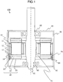
- Fig. 1 is a vertical cross-sectional view taken in a direction of a rotating shaft of an axial gap type electric machine 100 (hereinafter simply referred to as an electric machine 100) according to a first embodiment to which the present invention is adapted.
- the electric machine 100 includes a stator 10 having an approximately annular shape and two disk-shaped rotors 20 disposed to sandwich the stator in a direction of a rotating shaft.
- the rotors 20 are disposed to face each other in an axial direction via a predetermined gap.
- the rotors 20 are fixed such that the center portion of the rotors 20 rotate along with a shaft (rotating shaft) 50, and a load side and a non-load side of the shaft 50 are supported by a bracket 40 via a bearing 60, 60.
- the bracket 40 is fixed with a bolt or the like to the end portion of a housing 30 near the outer diameter, the housing 30 having an approximately cylindrical shape.
- the rotors 20 each include a magnet 21, a back yoke 22, and a yoke 23.
- the magnet 21 is a permanent magnet, and various kinds of magnets such as neodymium or ferrite can be used according to specifications.
- the back yoke 22 serves as a base of the rotor 20, has a disk shape, and includes a plurality of magnets 21 fixed on one end face of the back yoke 22 via the yoke 23 with an adhesive or by mechanical fixing.
- the magnet 21 is wedge-shaped for each pole, and the magnets 21 are arranged annularly with one faces of adjacent magnets in the axial direction having different poles (S, N).
- the stator 10 is formed by arranging a plurality of core units (twelve core units in this embodiment) 14 annularly about the shaft 50, with each core unit 14 being wound by the winding 12 via the bobbin 13 made of an insulating member around the outer periphery of the core 11.
- the stator 10 includes a molding resin 15 covering, partially or entirely, adjacent core units 14 and inner and outer periphery sides and axially end faces of the annular body, for example, to fix or insulate the stator 10 formed of the annular body to and from the housing 30.
- a crossover wire 70 drawn out from each core unit 14 is disposed on a non-load side (lower portion of the drawing) end face of the stator 10 and the inner periphery side of the housing 30 via a wiring piece (wiring support portion) 80.
- stator 10 includes a molding resin 15 covering, partially or entirely, adjacent core units 14 and the inner and outer periphery sides and axially end faces of the annular body to fix or insulate between the stator 10 and the wiring piece 80 formed of the annular body, and to fix or insulate these elements to and from the housing 30.
- Fig. 2 schematically illustrates an example structure of the core unit 14.
- Fig. 2(a) is a perspective view schematically illustrating an external structure of the core 11.
- the core 11 is formed by layering, for example, steel plates in a radial direction to provide a column-shaped body having an approximately trapezoidal cross-section in the direction of a rotating shaft center.
- the layering members may be foils or the like instead of steel plates.
- amorphous foils are layered.
- the layering members increase their widths gradually in the rotating direction as the layering members proceed from the rotating shaft in the radial direction.
- the core 11 becomes column-shaped with an approximately trapezoidal cross section.
- the cross-section may be in a circular or diamond shape.
- the core 11 may not be formed of the layered body, and may be provided as a core by shaving or pressed powder molding.
- the core 11 may be a column-shaped body having partially different measurements in the rotating direction or radial direction.
- Fig. 2(b) is a perspective view illustrating an outer structure of the bobbin 13.
- the bobbin 13 is made of an insulating member such as resin, and includes a tubular portion 13b extending in the axial direction and a guard portion 13a extending for a predetermined width in the rotating direction along the shape of an edge of an opening of the tubular portion 13b near both end portions of the opening.
- the tubular portion 13b includes an inner tubular portion that approximately matches the shape and size of the outer periphery shape of the core 11 to allow insertion of the core 11 into the inner tubular portion.
- the core 11 may be set in a molding tool so that the bobbin 13 can be formed by injection molding.
- Fig. 2(c) is a perspective view illustrating the structure of the core unit 14.
- the core unit 14 includes a winding 12 over an outer tube of the tubular portion 13b of the bobbin 13.
- the winding 12 is wound between two guard portions 13a formed near both ends in the axial direction.
- the core units 14 formed as described above are arranged annularly about the rotating shaft, as illustrated in Fig. 3(a) .
- connecting members 35 for connecting adjacent core units 14 are fixed to the outer diameter side of the guard portions 13a of the bobbins to connect the end portions of the adjacent connecting members 35.
- the stator 10 is put in the housing 30 with wiring pieces 80 which are described later.
- the stator 10 is sandwiched by the resin mold inserted from both openings of the housing 30 and molded by sealing with the molding resin 15.
- the connecting members 35 may not always be needed in the embodiment of the present invention. Alternatively, other fixing members may be used to maintain the annular state of the stator 10, or no fixing members may be used.
- the winding 12 of each core unit 14 is drawn out as the crossover wire 70 toward one side of the axial direction of the stator 10.
- a plurality of drawn-out crossover wires 70 are arranged to extend near the outer diameter of one end face in the axial direction of the stator 10 and along the inner periphery of the housing 30 in the rotating direction. More specifically, the crossover wire 70 is disposed to extend along other crossover wires 70 arranged in the rotating direction along the inner periphery of the housing 30.
- the crossover wires 70 then go out of an outlet 31 (see Fig. 6 ) of the housing 30.
- a part of the crossover wires 70 is disposed along the inner periphery of the housing so as to partially overlap a horizontal projection plane of the rotor 20.
- the outer peripheral side of the rotor 20 is partially or entirely located in a non-contact manner closer to the shaft center side than the crossover wires 70 arranged in the axial direction over the inner periphery of the housing. This achieves flatness in the axial direction of the machine which is one of the characteristics of the axial gap type rotary electric machine.
- the crossover wires 70 extending out of the housing 30 are connected to a power source terminal via a terminal box or the like.
- Figs. 4 , 5 , and 6 schematically illustrate the structure of the wiring piece 80.
- Fig. 4(a) is a perspective view of the wiring piece 80 observed from the outer periphery side of the electric machine 100.
- Fig. 4(b) is a perspective view observed from the inner periphery side of the electric machine 100.
- the wiring piece 80 is made of an insulating member, and preferably a high molecular insulating member.
- the wiring piece 80 is arc-shaped along the inner peripheral surface of the housing 30.
- the wiring piece 80 includes a base 81 on the inner diameter side, and a plurality of guide portions 88 on the outer diameter side of the base 81, the guide portions 88 serving as "grooves" for guiding the crossover wire in the rotating direction.
- the base 81 has an extension width spanning over the axially end surface side and the outer diameter side of the core units 14 (two core units in the present embodiment) and a width in the axial direction.
- the base 81 is arc-shaped, which enables arrangement of the crossover wire 70 in an arc shape. That is, linearly arranging the crossover wire 70 is limited, and shifting the crossover wire 70 toward the shaft center side core can be prevented.
- the guide portions 88 are disposed on the outer diameter side of the base 81 at predetermined intervals in the rotating direction.
- one wiring piece 80 includes three guide portions 88 disposed in the rotating direction.
- Each guide portion 88 includes guiding projections 88a (protrusions) in the axial direction for more than a few crossover wires 70.
- one wiring piece 80 includes a plurality of guide portions 88 each formed of a set of the guiding projections 88a disposed in the axial direction, and such guide portions 88 are disposed in the rotating direction.
- the guiding projections 88a are shaped to extend toward the inner periphery of the housing 30, each having a width at least larger than the diameter measurement of the crossover wire 70 from the base 81, and also extend in the rotating direction by a predetermined width.
- the crossover wire 70 is arranged in a gap (groove) between the guiding projections 88a and guided to the outlet 31 (see Fig. 7 ) via adjacent guide portion 88 through its guiding projections 88a.
- the crossover wire 70 is arranged to extend in either left or right direction, i.e., whichever shorter direction to the outlet 31 relative to a reference position that is radially point-symmetric to the outlet 31. This decreases the length of the entire crossover wire 70 extending in the axis direction, while reducing the number of layers of the crossover wire 70 arranged in the axial direction, to enable further decrease of the shaft axis of the electric machine 100.
- the guiding projections 88a each have a retaining portion 82 at its tip end on the inner periphery side of the housing to extend the load side and/or the non-load side for a predetermined width.
- the retaining portion 82 and the opposite retaining portion 82 adjacent to each other in the axial direction form a gap equivalent to or smaller than the diameter measurement of the crossover wire 70 to prevent dropout of the crossover wire 70 disposed between the guiding projection 88a.
- the distance between both edges of the groove opening is smaller than the storage region of the crossover wire 70 in the axial direction.
- this achieves an effect of preventing incomplete molding of the crossover wire 70 in sealing the molding resin 15 when the sealing pressure presses the crossover wire 70 toward the housing from between the guiding projections 88a.
- the retaining portion 82 is also effective in preventing the crossover wire 70 from touching the inner periphery of the housing due to vibrations or the like of the rotary electric machine 100 during activation as well as molding. This further improves reliability of insulation.
- the base 81 includes radial through holes 86 that penetrate through the base 81 from the bottom of the gaps (bottom of the grooves) between the guiding projections 88a.
- the radial through holes 86 facilitate go-around of the resin during resin molding.
- Fig. 5 is an enlarged view of an axially vertical cross-section (cross-section along line A-A of Fig. 4 ) of the wiring piece 80.
- d2 > d1 is satisfied, where d1 represents a width between the retaining portions 82 in the axial direction, and d2 represents a width of the radial through hole 86 in the axial direction.
- the crossover wires 70 are pressed toward the housing side by the pressure of the resin sealing pressure from the shaft center side via radial through holes 86, while the retaining portion 82 serves to prevent the crossover wires 70 from coming out of the guiding projections 88a toward the housing side, thus maintaining the positions of the crossover wires 70.
- the wiring piece 80 includes a continuous guiding projection 88b along the arc shape of the base 81 at the end of the base 81 opposite to the stator 10 in the axial direction.
- the continuous guiding projection 88b extends radially and has the same width as the width of the guiding projections 88a toward the housing side of the base 81, while also extending in the left and right rotating directions from the center of the base 81.
- the continuous guiding projection 88b serves to reinforce the base 81, while the surface of the continuous guiding projection 88b on the core unit 14 side serves as the region for arranging the crossover wire 70 similar to the guiding projections 88a.
- the continuous guiding projection 88b includes a plurality of flow channel projections (protrusions) 83a on the surface of the continuous guiding projection 88b opposite to the stator 10 in the axial direction.
- the plurality of flow channel projections (protrusions) 83a extend at equal widths in the axial direction and are disposed at equal intervals in the rotating direction.
- Each flow channel projection 83a also extends toward the shaft center side, so that the tip end of the flow channel projection 83a in the axial direction comes to abut the resin mold during the resin molding.
- the base 81 further includes, on its surface on the shaft center side, other flow channel projections (protrusions) 83b each extending continuously from the individual flow channel projections 83a in the axial direction (see Fig. 4(b) ).
- the flow channel projections 83b also come to touch the resin mold at their tip ends on the shaft center side during the resin molding. In the resin molding with the resin mold, the flow channel projections 83a and 83b form gaps serving as flow channels relative to the resin mold, thus facilitating go-around of the resin.
- the tip ends in the extending direction of the flow channel projections 83a and 83b maintain their abutment with the resin mold to fix the position and hold the posture of the wiring piece 80 and fill the gaps formed by the flow channel projections 83a and 83b sufficiently with the molding resin 15. Accordingly, the increase and maintaining of the thickness of the molding resin 15 disposed between the flow channel projections and the resin mold can be achieved, and peel-off of the molding resin due to vibrations during activation or degradation with aging of the electric machine 100 can be prevented.
- the flow channel projections 83a and 84b also achieve an effect of increasing the rigidity of the wiring piece 80.
- a positioning portion 84 is a projection extending in the axial direction to position the wiring piece 80 relative to the core units 14 disposed annularly.
- the positioning portion 84 is configured to insert into a gap or the like between adjacent guard portions 13a of two core units 14.
- the positioning portion 84 is disposed in the center in the rotating direction of the wiring piece 80.
- the embodiment of the present invention may be configured such that a plurality of projections is provided, or a protrusion is formed on the core unit 14 side such as the bobbin guard portion 13a and the wiring piece 80 has a corresponding recess, for example, that fits the protrusion.
- Fig. 6 schematically illustrates the wiring pieces 80 disposed in the core units 14 that are disposed annularly. Assume that, in the drawing, the wiring piece 80 is installed on the non-load side of the electric machine 100.
- More than one wiring piece 80 is disposed over the end portion of the outer diameter of the core units 14 (two core units in the present embodiment) in the rotating direction.
- one wiring piece 80 is disposed to step over a set of the core units 14, while other wiring pieces 80 are disposed for each set of core units 14.
- one wiring piece 80 includes (to step over) one set of core units 14, so that excessive bulging of the storage region of the crossover wire 70 in the shaft center direction can be prevented and, correspondingly, the diameter of the rotor 20 can be maintained.
- the rotor 20 can be disposed closer to the stator 10 such that at least part of the projection surface of the wiring piece 80 and the rotor 20 on the outer diameter side can overlap.
- the effect of reduction in length in the axial direction can also be expected.
- Fig. 7 schematically illustrates the stator 10 with the wiring pieces 80 disposed therein in the housing 30.
- the crossover wire 70 drawn out of each core unit 14 passes through the wiring piece 80 disposed on the own core unit and adjacent wiring pieces 80 in turn in the rotating direction, and is finally drawn out of the outlet 31 to the outside of the housing 30.
- the resin mold (not illustrated) is inserted from both opening ends of the housing 30 to integrally cover the stator 10, the wiring pieces 80, the crossover wires, and the inner periphery of the housing with the molding resin 15.
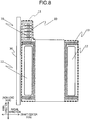
- Fig. 8 schematically illustrates the cross-section along line B-B of Fig. 7 including the core unit 14, the wiring piece 80, the molding resin 15, and the like.
- the wiring piece 80 is covered integrally by the molding resin 15 with the stator 10.
- the insulating characteristic of the crossover wires 70 can be improved and maintained, because the flow channel projections 83a, 83b and the radial through holes 86 facilitate go-around of the molding resin 15 sufficiently between the guiding projections 88a and 88b (the region where the crossover wires 70 are arranged). Accordingly, advantageous effects such as maintaining thermal stress or anti-vibration characteristic during activation and preventing dropout or peel-off from the wiring pieces 80 can be expected.
- the electric machine 100 is configured such that the wiring pieces 80 that are integrally molded are provided over the core units 14 in the rotating direction, so that the holding force of the crossover wires 70 formed as lines can increase.
- the flow channel projections 83a and 83b and the radial through holes 86 of the wiring piece 80 facilitate go-around of the molding resin 15 to each part of the crossover wire 70 and the wiring piece. The effect of sufficient fill-in of the molding resin 15, therefore, can be expected even when one wiring piece 80 is made to have a very long shape extending in the rotating direction.
- the wiring piece 80 prevents damage of the crossover wire 70. Meanwhile, the arc shape of the wiring piece 80 prevents movement of the crossover wire 70 toward the inner diameter side and limiting the region where the rotor 20 is disposed. Further, the fact that the flow channel projections 83a and 84b abut the resin mold can improve the positioning of and holding the posture of the wiring pieces 80, and increase the thickness of the resin at the wiring pieces 80 to increase the reliability.
- a wiring piece according to a second embodiment to which the present invention is adapted will be described.
- a wiring piece 180 of the second embodiment differs from the wiring piece of the first embodiment mainly in that the portion of the base located on the core unit side of the guiding projections extends further in the axial direction.
- the crossover wires arranged on the wiring piece extend in the rotating direction along the shape of the inner periphery of the housing, are collected at one location in the rotating direction, and are drawn from the outlet or the like to the outside.
- the outlet or the like is not always located to the same position as the collecting position of the crossover wires, due to the structural reason of the equipment to which the electric machine is installed or the structural reason of the electric machine itself. Even if the position of the outlet does not change, it may be necessary to adjust the position of drawing position of the crossover wires in the outlet. In a case where the collecting position of the crossover wires is shifted from the position of the outlet in the axial direction, it is preferable to avoid extending the collected crossover wires by the shifted distance in the axial direction in view of maintaining the crossover wires 70 and vibrations and reliability of the structure.
- a main characteristic of the second embodiment is that the wiring piece includes the crossover wire 70 that can be held with its insulating characteristic being maintained, while the collecting position of the crossover wires 70 is adjustable in the axial direction.
- Fig. 9(a) is a perspective view of a wiring piece 180 according to the second embodiment observed from the outer diameter side.
- Fig. 9(b) is a perspective view schematically illustrating the wiring piece 180 observed from the shaft center side.
- a base 181 of the wiring piece 180 has an extended shape toward the stator 10 from the guide portion 88 (the drawing indicates an extended portion 181a).
- the extended portion 181a is illustrated exemplarily as having a larger width than the width of the guide portion 88 in the axial direction, but any width may be used for the extended portion in the embodiment of the present invention.
- the wiring piece 181 includes a thick portion 182 at the extended portion 181a.
- the thick portion 182 has an approximately the same width in the axial direction as the extending width of the guide portion 88 at a position coinciding with the guide portion 88 in the axial direction.
- the thick portion 182 is thick between the extended portion 181a and the inner periphery side of the housing, with the thickness being equal to the extending width of the guiding projections 88a.
- the projection surface of the thick portion 181a has an outer circle (approximately trapezoidal) shape overlapping the projection surface in the axial direction with the guiding projections 88a.
- the thick portion 181a also serves as a reinforcement member of the extended portion 181a.
- the thick portion 181a has a tapered through hole 191 expanding from the base 181 side to the inner periphery side of the housing.
- the through hole 191 facilitates go-around of the molding resin 15 toward the inner periphery side of the housing of the extended portion 190.
- Fig. 10 illustrates a modification of the wiring piece 180 of the second embodiment.
- Fig. 10(a) is a perspective view of a wiring piece 180H according to the modification observed from the outer diameter side.
- Fig. 10(b) is a perspective view schematically illustrating the wiring piece 180H observed from the shaft center side.
- the modification differs from the second embodiment mainly in that the base 181 further includes through holes 191H.
- Each through hole 191H is located between both ends of the base 181 in the rotating direction and between the thick portion 182 and the guide portion 88 disposed adjacent to each other in the rotating direction.
- the through holes 191H are rectangular-shaped with vertically long sides in the axial direction.
- the through holes 191H may be in other shape formed of, for example, a plurality of through holes 191H each having a small diameter disposed in the axial direction.
- the through holes 191H provided in the base 181 facilitates go-around of the resin for the wiring piece 180 extending in the axial direction by the extended portion 181a.
- Fig. 11(a) schematically illustrates the wiring pieces 191H and the stator 10 disposed in the housing 30.
- Fig. 11(b) is a partial enlarged view of a portion surrounded by a dot line of Fig. 11(a) .
- the end face of the stator 10 in the axial direction is apart from the opening edge of the outlet 31 on the stator side by a distance L1 in the axial direction (which is larger than the separation distance of the first embodiment illustrated in Fig. 7 ).
- a distance between the groove for arranging the crossover wire located nearest to the stator 10 of the wiring piece 180 and the end face of the stator 10 in the axial direction is smaller than L1
- a part of or the entire length of the crossover wire 70 is arranged (e.g., arranged obliquely) in the outlet 31 via the region L1 from each groove when the crossover wires 70 go out of the outlet 31.
- This structure may damage the stability of the crossover wire 70 relative to the sealing pressure of the molding resin 15 or the vibrations in activation of the electric machine.
- the extended portion 181a of the wiring piece 191H serves as a buffer to compensate for the difference of the separation L1 to match the horizontal position of all crossover wires 70 disposed on the wiring pieces 191H to the outlet 31.
- the crossover wires 70 disposed on the wiring pieces 191H are located horizontally in the opening width of the outlet 31 in the axial direction, preventing improper bending or posture of the crossover wires 70 that are bundled near the outlet 31, thus guarantees stability of the crossover wires 70.
- the extended portion 181a may increase structural resistance in going around of resin, the through holes 191 or 191H eliminates such resistance and allows maintaining of and insulating characteristics of the crossover wires 70 simultaneously.
- the maintaining of and the insulating characteristic of the crossover wires 70 can be achieved, while providing variable distance in the axial direction with the outlet.
- the wiring piece 80 (180, 180H) and the core unit 14 are arranged using the positioning portion 84.
- these components may be fixed with each other with, for example, an adhesive, bolts, rivets, or other engagement members.
- each crossover wire 70 is arranged in the groove (gap) formed by two guiding projections 88a.
- two or more crossover wires 70 are arranged in one groove (gap) in the radial or axial direction. This reduced the diameter measurement or the axial measurement of the electric machine 100 according to specifications.
- the housing 30, the core units 14, and the wiring pieces are integrally covered by the molding resin 15.
- a resin mold disposed on the outer periphery side may be used instead of the housing 30. This structure can be adapted to a case of manufacturing a resin mold stator as a part, or manufacturing and disposing such a resin mold stator in the housing 30 and fixing it with an adhesive, bolts, or engagement members.
- the wiring pieces are disposed on the non-load side of the electric machine 100, but may also be disposed on the load side.
- the armature structure including one stator and two rotors has been described, but the structure may include two stators and one rotor, or two or more stators and rotors.
Landscapes
- Engineering & Computer Science (AREA)
- Power Engineering (AREA)
- Insulation, Fastening Of Motor, Generator Windings (AREA)
- Motor Or Generator Frames (AREA)
Applications Claiming Priority (1)
| Application Number | Priority Date | Filing Date | Title |
|---|---|---|---|
| PCT/JP2016/064673 WO2017199355A1 (fr) | 2016-05-18 | 2016-05-18 | Machine électrique rotative à entrefer axial |
Publications (3)
| Publication Number | Publication Date |
|---|---|
| EP3460960A1 true EP3460960A1 (fr) | 2019-03-27 |
| EP3460960A4 EP3460960A4 (fr) | 2020-01-08 |
| EP3460960B1 EP3460960B1 (fr) | 2022-02-23 |
Family
ID=60325110
Family Applications (1)
| Application Number | Title | Priority Date | Filing Date |
|---|---|---|---|
| EP16902374.4A Not-in-force EP3460960B1 (fr) | 2016-05-18 | 2016-05-18 | Machine électrique rotative à entrefer axial |
Country Status (6)
| Country | Link |
|---|---|
| US (1) | US10992203B2 (fr) |
| EP (1) | EP3460960B1 (fr) |
| JP (1) | JP6596584B2 (fr) |
| CN (1) | CN108604845B (fr) |
| TW (2) | TWI646758B (fr) |
| WO (1) | WO2017199355A1 (fr) |
Cited By (4)
| Publication number | Priority date | Publication date | Assignee | Title |
|---|---|---|---|---|
| EP3576257A4 (fr) * | 2017-01-27 | 2020-08-19 | Hitachi Industrial Equipment Systems Co., Ltd. | Machine tournante électrique de type à entrefer axial |
| EP4040647A1 (fr) * | 2021-02-05 | 2022-08-10 | Li-Ho Yao | Cadre de câblage, stator de moteur et moteur les appliquant |
| US20250105680A1 (en) * | 2021-08-09 | 2025-03-27 | Amotech Co., Ltd. | Stator having bus bar structure, propeller driving motor using same, and method for manufacturing stator |
| US12620841B2 (en) * | 2021-08-09 | 2026-05-05 | Amotech Co., Ltd. | Stator having bus bar structure, propeller driving motor using same, and method for manufacturing stator |
Families Citing this family (6)
| Publication number | Priority date | Publication date | Assignee | Title |
|---|---|---|---|---|
| WO2023048227A1 (fr) * | 2021-09-27 | 2023-03-30 | 株式会社デンソー | Machine électrique tournante |
| JP2024064259A (ja) * | 2022-10-27 | 2024-05-14 | 株式会社日立産機システム | 回転電機 |
| DE102023201543A1 (de) * | 2023-02-21 | 2024-08-22 | Brose Fahrzeugteile SE & Co. Kommanditgesellschaft, Würzburg | Elektromotor eines Nebenaggregats eines Kraftfahrzeugs |
| FR3152674A1 (fr) * | 2023-09-01 | 2025-03-07 | Renault | Machine électrique à flux axial et procédé de montage correspondant |
| US20250239904A1 (en) * | 2024-01-18 | 2025-07-24 | Flowserve Pte. Ltd. | Coil assembly of an integrated motor pump or turbine having reduced thermal stress at cryogenic temperatures |
| KR102898564B1 (ko) * | 2024-06-28 | 2025-12-09 | 한국생산기술연구원 | 축방향 자속 모터 및 그의 제조 방법 |
Family Cites Families (30)
| Publication number | Priority date | Publication date | Assignee | Title |
|---|---|---|---|---|
| JP3607977B2 (ja) * | 1999-10-04 | 2005-01-05 | トヨタ自動車株式会社 | モールドモータ |
| US6856055B2 (en) | 2002-07-11 | 2005-02-15 | Emerson Electric Co. | Interconnecting ring and wire guide |
| JP4305649B2 (ja) | 2003-02-26 | 2009-07-29 | 株式会社富士通ゼネラル | アキシャルギャップ型電動機 |
| JP4725721B2 (ja) * | 2005-01-24 | 2011-07-13 | 株式会社富士通ゼネラル | アキシャルエアギャップ型電動機 |
| JP2007014147A (ja) * | 2005-06-30 | 2007-01-18 | Fujitsu General Ltd | 電動機 |
| JP4956774B2 (ja) * | 2005-08-24 | 2012-06-20 | 日産自動車株式会社 | アキシャルギャップ型モータの結線構造 |
| CN2822017Y (zh) | 2005-09-12 | 2006-09-27 | 朱洪来 | 轴向磁路双驱动式无刷无齿直流轮毂电机 |
| JP4868147B2 (ja) | 2006-11-08 | 2012-02-01 | 株式会社富士通ゼネラル | アキシャルエアギャップ型電動機 |
| JP2008125278A (ja) * | 2006-11-14 | 2008-05-29 | Fujitsu General Ltd | アキシャルエアギャップ型電動機 |
| JP2008131682A (ja) * | 2006-11-16 | 2008-06-05 | Fujitsu General Ltd | アキシャルエアギャップ型電動機 |
| DE102008024378A1 (de) | 2008-05-20 | 2009-12-03 | Miele & Cie. Kg | Elektromotor mit Sensor und/oder Thermoschutzschalter |
| TWM359868U (en) | 2009-01-05 | 2009-06-21 | zhen-xing Huang | Iron core structure of motor |
| JP5509607B2 (ja) | 2009-02-05 | 2014-06-04 | 株式会社富士通ゼネラル | アキシャルエアギャップ型電動機 |
| JP5319407B2 (ja) | 2009-06-04 | 2013-10-16 | 本田技研工業株式会社 | 圧入装置及びアキシャルギャップ型回転電機のステータの製造方法 |
| US8482180B2 (en) | 2010-10-20 | 2013-07-09 | Asmo Co., Ltd. | Stator, brushless motor, and manufacturing method of the same |
| JP5166566B2 (ja) * | 2011-03-31 | 2013-03-21 | 株式会社小松製作所 | インシュレータおよびこれを備えたステータ、モータ |
| JP2013118750A (ja) | 2011-12-02 | 2013-06-13 | Hitachi Ltd | アキシャルギャップ型回転電機及びその製造方法 |
| WO2013121590A1 (fr) | 2012-02-17 | 2013-08-22 | 株式会社日立製作所 | Machine électrique tournante |
| JP5965228B2 (ja) | 2012-07-06 | 2016-08-03 | 株式会社日立製作所 | アキシャルギャップ型回転電機 |
| DE102012020329A1 (de) * | 2012-10-17 | 2014-04-17 | Sew-Eurodrive Gmbh & Co Kg | Elektromotor und Verfahren zum Herstellen eines Elektromotors |
| JP5851432B2 (ja) * | 2013-02-08 | 2016-02-03 | 株式会社日立製作所 | 回転電機 |
| JP6073763B2 (ja) | 2013-08-30 | 2017-02-01 | 株式会社日立産機システム | アキシャルギャップ型永久磁石同期電動機 |
| CN203660698U (zh) | 2013-12-27 | 2014-06-18 | 中山大洋电机制造有限公司 | 一种电机定子铁芯上的端部绝缘结构及其应用的塑封电机 |
| JP6463895B2 (ja) | 2014-02-28 | 2019-02-06 | 日本電産テクノモータ株式会社 | モータ用ステータ及びその製造方法 |
| JP2015171239A (ja) * | 2014-03-07 | 2015-09-28 | アイシン精機株式会社 | 回転電機のステータ及び回転電機 |
| CN106416025B (zh) | 2014-04-11 | 2019-06-07 | 株式会社日立产机系统 | 轴向气隙型旋转电机 |
| US11165312B2 (en) | 2014-04-14 | 2021-11-02 | Hitachi Industrial Equipment Systems Co., Ltd. | Axial-gap dynamo-electric machine |
| JP2016059208A (ja) * | 2014-09-11 | 2016-04-21 | 日立オートモティブシステムズ株式会社 | 電動流体ポンプ |
| DE102014221188A1 (de) | 2014-10-20 | 2016-04-21 | Bayerische Motoren Werke Aktiengesellschaft | Schaltringanordnung für eine elektrische Maschine |
| JP6416965B1 (ja) * | 2017-03-31 | 2018-10-31 | 本田技研工業株式会社 | コイル巻回部品及び回転電機 |
-
2016
- 2016-05-18 US US16/097,738 patent/US10992203B2/en active Active
- 2016-05-18 JP JP2018517986A patent/JP6596584B2/ja active Active
- 2016-05-18 EP EP16902374.4A patent/EP3460960B1/fr not_active Not-in-force
- 2016-05-18 WO PCT/JP2016/064673 patent/WO2017199355A1/fr not_active Ceased
- 2016-05-18 CN CN201680081215.8A patent/CN108604845B/zh active Active
-
2017
- 2017-04-12 TW TW106112279A patent/TWI646758B/zh active
- 2017-04-12 TW TW107140641A patent/TWI727223B/zh active
Cited By (5)
| Publication number | Priority date | Publication date | Assignee | Title |
|---|---|---|---|---|
| EP3576257A4 (fr) * | 2017-01-27 | 2020-08-19 | Hitachi Industrial Equipment Systems Co., Ltd. | Machine tournante électrique de type à entrefer axial |
| EP4040647A1 (fr) * | 2021-02-05 | 2022-08-10 | Li-Ho Yao | Cadre de câblage, stator de moteur et moteur les appliquant |
| US20250105680A1 (en) * | 2021-08-09 | 2025-03-27 | Amotech Co., Ltd. | Stator having bus bar structure, propeller driving motor using same, and method for manufacturing stator |
| EP4387059A4 (fr) * | 2021-08-09 | 2025-08-13 | Amotech Co Ltd | Stator ayant une structure de barre omnibus, moteur d'entraînement d'hélice l'utilisant, et procédé de fabrication de stator |
| US12620841B2 (en) * | 2021-08-09 | 2026-05-05 | Amotech Co., Ltd. | Stator having bus bar structure, propeller driving motor using same, and method for manufacturing stator |
Also Published As
| Publication number | Publication date |
|---|---|
| EP3460960A4 (fr) | 2020-01-08 |
| US10992203B2 (en) | 2021-04-27 |
| TWI727223B (zh) | 2021-05-11 |
| JP6596584B2 (ja) | 2019-10-23 |
| TW201742356A (zh) | 2017-12-01 |
| TWI646758B (zh) | 2019-01-01 |
| CN108604845B (zh) | 2020-06-16 |
| JPWO2017199355A1 (ja) | 2018-10-18 |
| TW201907645A (zh) | 2019-02-16 |
| US20200395808A1 (en) | 2020-12-17 |
| WO2017199355A1 (fr) | 2017-11-23 |
| CN108604845A (zh) | 2018-09-28 |
| EP3460960B1 (fr) | 2022-02-23 |
Similar Documents
| Publication | Publication Date | Title |
|---|---|---|
| EP3460960B1 (fr) | Machine électrique rotative à entrefer axial | |
| JP4404199B2 (ja) | 同期電動機 | |
| EP3193428B1 (fr) | Stator | |
| CN102369651B (zh) | 电机的定子 | |
| EP2660956A1 (fr) | Machine électrique tournante | |
| US20140175935A1 (en) | Rotary electric machine | |
| EP3576259B1 (fr) | Machine électrique tournante du type à entrefer axial et son procédé de production | |
| JP2015091146A (ja) | 集中巻回転電機のステータ、及びこれを備えた回転電機 | |
| JP2018133934A (ja) | ブラシレスモータ | |
| WO2005076437A1 (fr) | Stator de moteur | |
| WO2019073724A1 (fr) | Stator pour machine dynamo-électrique | |
| EP1713157B1 (fr) | Stator de moteur electrique | |
| EP2738916A2 (fr) | Stator d'un moteur électrique comprenant un corps de bobine isolant | |
| WO2018087882A1 (fr) | Machine dynamoélectrique | |
| EP2031735B1 (fr) | Stator et moteur électrique | |
| KR20220069644A (ko) | 모터 | |
| US20130127267A1 (en) | Cylindrical linear motor with laminated stator | |
| CN108702054B (zh) | 轴向间隙型旋转电机 | |
| WO2015174277A1 (fr) | Machine électrique tournante et son procédé de fabrication | |
| EP3579386A1 (fr) | Machine électrique tournante à entrefer axial | |
| JP5665362B2 (ja) | 回転電機 | |
| JP2020124057A (ja) | 回転電機のインシュレータ | |
| CN110637405B (zh) | 旋转电机的定子 | |
| CN220797912U (zh) | 定子组件、直线电机、电磁减震器和车辆 | |
| CN120566767A (zh) | 定子及马达 |
Legal Events
| Date | Code | Title | Description |
|---|---|---|---|
| STAA | Information on the status of an ep patent application or granted ep patent |
Free format text: STATUS: THE INTERNATIONAL PUBLICATION HAS BEEN MADE |
|
| PUAI | Public reference made under article 153(3) epc to a published international application that has entered the european phase |
Free format text: ORIGINAL CODE: 0009012 |
|
| STAA | Information on the status of an ep patent application or granted ep patent |
Free format text: STATUS: REQUEST FOR EXAMINATION WAS MADE |
|
| 17P | Request for examination filed |
Effective date: 20181218 |
|
| AK | Designated contracting states |
Kind code of ref document: A1 Designated state(s): AL AT BE BG CH CY CZ DE DK EE ES FI FR GB GR HR HU IE IS IT LI LT LU LV MC MK MT NL NO PL PT RO RS SE SI SK SM TR |
|
| AX | Request for extension of the european patent |
Extension state: BA ME |
|
| DAV | Request for validation of the european patent (deleted) | ||
| DAX | Request for extension of the european patent (deleted) | ||
| A4 | Supplementary search report drawn up and despatched |
Effective date: 20191209 |
|
| RIC1 | Information provided on ipc code assigned before grant |
Ipc: H02K 3/52 20060101ALI20191203BHEP Ipc: H02K 21/24 20060101ALI20191203BHEP Ipc: H02K 3/50 20060101AFI20191203BHEP |
|
| STAA | Information on the status of an ep patent application or granted ep patent |
Free format text: STATUS: EXAMINATION IS IN PROGRESS |
|
| 17Q | First examination report despatched |
Effective date: 20210112 |
|
| GRAP | Despatch of communication of intention to grant a patent |
Free format text: ORIGINAL CODE: EPIDOSNIGR1 |
|
| STAA | Information on the status of an ep patent application or granted ep patent |
Free format text: STATUS: GRANT OF PATENT IS INTENDED |
|
| INTG | Intention to grant announced |
Effective date: 20211112 |
|
| GRAS | Grant fee paid |
Free format text: ORIGINAL CODE: EPIDOSNIGR3 |
|
| GRAA | (expected) grant |
Free format text: ORIGINAL CODE: 0009210 |
|
| STAA | Information on the status of an ep patent application or granted ep patent |
Free format text: STATUS: THE PATENT HAS BEEN GRANTED |
|
| RAP3 | Party data changed (applicant data changed or rights of an application transferred) |
Owner name: HITACHI INDUSTRIAL EQUIPMENT SYSTEMS CO., LTD. |
|
| AK | Designated contracting states |
Kind code of ref document: B1 Designated state(s): AL AT BE BG CH CY CZ DE DK EE ES FI FR GB GR HR HU IE IS IT LI LT LU LV MC MK MT NL NO PL PT RO RS SE SI SK SM TR |
|
| REG | Reference to a national code |
Ref country code: GB Ref legal event code: FG4D |
|
| REG | Reference to a national code |
Ref country code: CH Ref legal event code: EP |
|
| REG | Reference to a national code |
Ref country code: AT Ref legal event code: REF Ref document number: 1471198 Country of ref document: AT Kind code of ref document: T Effective date: 20220315 |
|
| REG | Reference to a national code |
Ref country code: IE Ref legal event code: FG4D |
|
| REG | Reference to a national code |
Ref country code: DE Ref legal event code: R096 Ref document number: 602016069477 Country of ref document: DE |
|
| REG | Reference to a national code |
Ref country code: LT Ref legal event code: MG9D |
|
| REG | Reference to a national code |
Ref country code: NL Ref legal event code: MP Effective date: 20220223 |
|
| REG | Reference to a national code |
Ref country code: AT Ref legal event code: MK05 Ref document number: 1471198 Country of ref document: AT Kind code of ref document: T Effective date: 20220223 |
|
| PG25 | Lapsed in a contracting state [announced via postgrant information from national office to epo] |
Ref country code: SE Free format text: LAPSE BECAUSE OF FAILURE TO SUBMIT A TRANSLATION OF THE DESCRIPTION OR TO PAY THE FEE WITHIN THE PRESCRIBED TIME-LIMIT Effective date: 20220223 Ref country code: RS Free format text: LAPSE BECAUSE OF FAILURE TO SUBMIT A TRANSLATION OF THE DESCRIPTION OR TO PAY THE FEE WITHIN THE PRESCRIBED TIME-LIMIT Effective date: 20220223 Ref country code: PT Free format text: LAPSE BECAUSE OF FAILURE TO SUBMIT A TRANSLATION OF THE DESCRIPTION OR TO PAY THE FEE WITHIN THE PRESCRIBED TIME-LIMIT Effective date: 20220623 Ref country code: NO Free format text: LAPSE BECAUSE OF FAILURE TO SUBMIT A TRANSLATION OF THE DESCRIPTION OR TO PAY THE FEE WITHIN THE PRESCRIBED TIME-LIMIT Effective date: 20220523 Ref country code: NL Free format text: LAPSE BECAUSE OF FAILURE TO SUBMIT A TRANSLATION OF THE DESCRIPTION OR TO PAY THE FEE WITHIN THE PRESCRIBED TIME-LIMIT Effective date: 20220223 Ref country code: LT Free format text: LAPSE BECAUSE OF FAILURE TO SUBMIT A TRANSLATION OF THE DESCRIPTION OR TO PAY THE FEE WITHIN THE PRESCRIBED TIME-LIMIT Effective date: 20220223 Ref country code: HR Free format text: LAPSE BECAUSE OF FAILURE TO SUBMIT A TRANSLATION OF THE DESCRIPTION OR TO PAY THE FEE WITHIN THE PRESCRIBED TIME-LIMIT Effective date: 20220223 Ref country code: ES Free format text: LAPSE BECAUSE OF FAILURE TO SUBMIT A TRANSLATION OF THE DESCRIPTION OR TO PAY THE FEE WITHIN THE PRESCRIBED TIME-LIMIT Effective date: 20220223 Ref country code: BG Free format text: LAPSE BECAUSE OF FAILURE TO SUBMIT A TRANSLATION OF THE DESCRIPTION OR TO PAY THE FEE WITHIN THE PRESCRIBED TIME-LIMIT Effective date: 20220523 |
|
| PG25 | Lapsed in a contracting state [announced via postgrant information from national office to epo] |
Ref country code: PL Free format text: LAPSE BECAUSE OF FAILURE TO SUBMIT A TRANSLATION OF THE DESCRIPTION OR TO PAY THE FEE WITHIN THE PRESCRIBED TIME-LIMIT Effective date: 20220223 Ref country code: LV Free format text: LAPSE BECAUSE OF FAILURE TO SUBMIT A TRANSLATION OF THE DESCRIPTION OR TO PAY THE FEE WITHIN THE PRESCRIBED TIME-LIMIT Effective date: 20220223 Ref country code: GR Free format text: LAPSE BECAUSE OF FAILURE TO SUBMIT A TRANSLATION OF THE DESCRIPTION OR TO PAY THE FEE WITHIN THE PRESCRIBED TIME-LIMIT Effective date: 20220524 Ref country code: FI Free format text: LAPSE BECAUSE OF FAILURE TO SUBMIT A TRANSLATION OF THE DESCRIPTION OR TO PAY THE FEE WITHIN THE PRESCRIBED TIME-LIMIT Effective date: 20220223 Ref country code: AT Free format text: LAPSE BECAUSE OF FAILURE TO SUBMIT A TRANSLATION OF THE DESCRIPTION OR TO PAY THE FEE WITHIN THE PRESCRIBED TIME-LIMIT Effective date: 20220223 |
|
| PG25 | Lapsed in a contracting state [announced via postgrant information from national office to epo] |
Ref country code: IS Free format text: LAPSE BECAUSE OF FAILURE TO SUBMIT A TRANSLATION OF THE DESCRIPTION OR TO PAY THE FEE WITHIN THE PRESCRIBED TIME-LIMIT Effective date: 20220623 |
|
| PG25 | Lapsed in a contracting state [announced via postgrant information from national office to epo] |
Ref country code: SM Free format text: LAPSE BECAUSE OF FAILURE TO SUBMIT A TRANSLATION OF THE DESCRIPTION OR TO PAY THE FEE WITHIN THE PRESCRIBED TIME-LIMIT Effective date: 20220223 Ref country code: SK Free format text: LAPSE BECAUSE OF FAILURE TO SUBMIT A TRANSLATION OF THE DESCRIPTION OR TO PAY THE FEE WITHIN THE PRESCRIBED TIME-LIMIT Effective date: 20220223 Ref country code: RO Free format text: LAPSE BECAUSE OF FAILURE TO SUBMIT A TRANSLATION OF THE DESCRIPTION OR TO PAY THE FEE WITHIN THE PRESCRIBED TIME-LIMIT Effective date: 20220223 Ref country code: EE Free format text: LAPSE BECAUSE OF FAILURE TO SUBMIT A TRANSLATION OF THE DESCRIPTION OR TO PAY THE FEE WITHIN THE PRESCRIBED TIME-LIMIT Effective date: 20220223 Ref country code: DK Free format text: LAPSE BECAUSE OF FAILURE TO SUBMIT A TRANSLATION OF THE DESCRIPTION OR TO PAY THE FEE WITHIN THE PRESCRIBED TIME-LIMIT Effective date: 20220223 Ref country code: CZ Free format text: LAPSE BECAUSE OF FAILURE TO SUBMIT A TRANSLATION OF THE DESCRIPTION OR TO PAY THE FEE WITHIN THE PRESCRIBED TIME-LIMIT Effective date: 20220223 |
|
| REG | Reference to a national code |
Ref country code: DE Ref legal event code: R097 Ref document number: 602016069477 Country of ref document: DE |
|
| PG25 | Lapsed in a contracting state [announced via postgrant information from national office to epo] |
Ref country code: AL Free format text: LAPSE BECAUSE OF FAILURE TO SUBMIT A TRANSLATION OF THE DESCRIPTION OR TO PAY THE FEE WITHIN THE PRESCRIBED TIME-LIMIT Effective date: 20220223 |
|
| PLBE | No opposition filed within time limit |
Free format text: ORIGINAL CODE: 0009261 |
|
| REG | Reference to a national code |
Ref country code: CH Ref legal event code: PL |
|
| STAA | Information on the status of an ep patent application or granted ep patent |
Free format text: STATUS: NO OPPOSITION FILED WITHIN TIME LIMIT |
|
| REG | Reference to a national code |
Ref country code: BE Ref legal event code: MM Effective date: 20220531 |
|
| GBPC | Gb: european patent ceased through non-payment of renewal fee |
Effective date: 20220523 |
|
| PG25 | Lapsed in a contracting state [announced via postgrant information from national office to epo] |
Ref country code: MC Free format text: LAPSE BECAUSE OF FAILURE TO SUBMIT A TRANSLATION OF THE DESCRIPTION OR TO PAY THE FEE WITHIN THE PRESCRIBED TIME-LIMIT Effective date: 20220223 Ref country code: LU Free format text: LAPSE BECAUSE OF NON-PAYMENT OF DUE FEES Effective date: 20220518 Ref country code: LI Free format text: LAPSE BECAUSE OF NON-PAYMENT OF DUE FEES Effective date: 20220531 Ref country code: CH Free format text: LAPSE BECAUSE OF NON-PAYMENT OF DUE FEES Effective date: 20220531 |
|
| 26N | No opposition filed |
Effective date: 20221124 |
|
| PG25 | Lapsed in a contracting state [announced via postgrant information from national office to epo] |
Ref country code: SI Free format text: LAPSE BECAUSE OF FAILURE TO SUBMIT A TRANSLATION OF THE DESCRIPTION OR TO PAY THE FEE WITHIN THE PRESCRIBED TIME-LIMIT Effective date: 20220223 |
|
| PG25 | Lapsed in a contracting state [announced via postgrant information from national office to epo] |
Ref country code: IE Free format text: LAPSE BECAUSE OF NON-PAYMENT OF DUE FEES Effective date: 20220518 Ref country code: FR Free format text: LAPSE BECAUSE OF NON-PAYMENT OF DUE FEES Effective date: 20220531 |
|
| PG25 | Lapsed in a contracting state [announced via postgrant information from national office to epo] |
Ref country code: GB Free format text: LAPSE BECAUSE OF NON-PAYMENT OF DUE FEES Effective date: 20220523 Ref country code: BE Free format text: LAPSE BECAUSE OF NON-PAYMENT OF DUE FEES Effective date: 20220531 |
|
| PG25 | Lapsed in a contracting state [announced via postgrant information from national office to epo] |
Ref country code: IT Free format text: LAPSE BECAUSE OF FAILURE TO SUBMIT A TRANSLATION OF THE DESCRIPTION OR TO PAY THE FEE WITHIN THE PRESCRIBED TIME-LIMIT Effective date: 20220223 |
|
| PG25 | Lapsed in a contracting state [announced via postgrant information from national office to epo] |
Ref country code: HU Free format text: LAPSE BECAUSE OF FAILURE TO SUBMIT A TRANSLATION OF THE DESCRIPTION OR TO PAY THE FEE WITHIN THE PRESCRIBED TIME-LIMIT; INVALID AB INITIO Effective date: 20160518 |
|
| PG25 | Lapsed in a contracting state [announced via postgrant information from national office to epo] |
Ref country code: MK Free format text: LAPSE BECAUSE OF FAILURE TO SUBMIT A TRANSLATION OF THE DESCRIPTION OR TO PAY THE FEE WITHIN THE PRESCRIBED TIME-LIMIT Effective date: 20220223 Ref country code: CY Free format text: LAPSE BECAUSE OF FAILURE TO SUBMIT A TRANSLATION OF THE DESCRIPTION OR TO PAY THE FEE WITHIN THE PRESCRIBED TIME-LIMIT Effective date: 20220223 |
|
| PG25 | Lapsed in a contracting state [announced via postgrant information from national office to epo] |
Ref country code: TR Free format text: LAPSE BECAUSE OF FAILURE TO SUBMIT A TRANSLATION OF THE DESCRIPTION OR TO PAY THE FEE WITHIN THE PRESCRIBED TIME-LIMIT Effective date: 20220223 |
|
| PGFP | Annual fee paid to national office [announced via postgrant information from national office to epo] |
Ref country code: DE Payment date: 20240328 Year of fee payment: 9 |
|
| PG25 | Lapsed in a contracting state [announced via postgrant information from national office to epo] |
Ref country code: MT Free format text: LAPSE BECAUSE OF FAILURE TO SUBMIT A TRANSLATION OF THE DESCRIPTION OR TO PAY THE FEE WITHIN THE PRESCRIBED TIME-LIMIT Effective date: 20220223 |
|
| REG | Reference to a national code |
Ref country code: DE Ref legal event code: R119 Ref document number: 602016069477 Country of ref document: DE |
|
| PG25 | Lapsed in a contracting state [announced via postgrant information from national office to epo] |
Ref country code: DE Free format text: LAPSE BECAUSE OF NON-PAYMENT OF DUE FEES Effective date: 20251202 |