EP3462034A1 - Pompe à vide - Google Patents
Pompe à vide Download PDFInfo
- Publication number
- EP3462034A1 EP3462034A1 EP17193821.0A EP17193821A EP3462034A1 EP 3462034 A1 EP3462034 A1 EP 3462034A1 EP 17193821 A EP17193821 A EP 17193821A EP 3462034 A1 EP3462034 A1 EP 3462034A1
- Authority
- EP
- European Patent Office
- Prior art keywords
- vacuum pump
- housing component
- pump
- cooling device
- housing
- Prior art date
- Legal status (The legal status is an assumption and is not a legal conclusion. Google has not performed a legal analysis and makes no representation as to the accuracy of the status listed.)
- Granted
Links
Images




Classifications
-
- F—MECHANICAL ENGINEERING; LIGHTING; HEATING; WEAPONS; BLASTING
- F04—POSITIVE - DISPLACEMENT MACHINES FOR LIQUIDS; PUMPS FOR LIQUIDS OR ELASTIC FLUIDS
- F04D—NON-POSITIVE-DISPLACEMENT PUMPS
- F04D29/00—Details, component parts, or accessories
- F04D29/58—Cooling; Heating; Diminishing heat transfer
- F04D29/5813—Cooling the control unit
-
- F—MECHANICAL ENGINEERING; LIGHTING; HEATING; WEAPONS; BLASTING
- F04—POSITIVE - DISPLACEMENT MACHINES FOR LIQUIDS; PUMPS FOR LIQUIDS OR ELASTIC FLUIDS
- F04D—NON-POSITIVE-DISPLACEMENT PUMPS
- F04D19/00—Axial-flow pumps
- F04D19/02—Multi-stage pumps
- F04D19/04—Multi-stage pumps specially adapted to the production of a high vacuum, e.g. molecular pumps
-
- F—MECHANICAL ENGINEERING; LIGHTING; HEATING; WEAPONS; BLASTING
- F04—POSITIVE - DISPLACEMENT MACHINES FOR LIQUIDS; PUMPS FOR LIQUIDS OR ELASTIC FLUIDS
- F04D—NON-POSITIVE-DISPLACEMENT PUMPS
- F04D29/00—Details, component parts, or accessories
- F04D29/58—Cooling; Heating; Diminishing heat transfer
- F04D29/582—Cooling; Heating; Diminishing heat transfer specially adapted for elastic fluid pumps
- F04D29/584—Cooling; Heating; Diminishing heat transfer specially adapted for elastic fluid pumps cooling or heating the machine
-
- F—MECHANICAL ENGINEERING; LIGHTING; HEATING; WEAPONS; BLASTING
- F04—POSITIVE - DISPLACEMENT MACHINES FOR LIQUIDS; PUMPS FOR LIQUIDS OR ELASTIC FLUIDS
- F04D—NON-POSITIVE-DISPLACEMENT PUMPS
- F04D29/00—Details, component parts, or accessories
- F04D29/58—Cooling; Heating; Diminishing heat transfer
- F04D29/582—Cooling; Heating; Diminishing heat transfer specially adapted for elastic fluid pumps
- F04D29/5853—Cooling; Heating; Diminishing heat transfer specially adapted for elastic fluid pumps heat insulation or conduction
-
- F—MECHANICAL ENGINEERING; LIGHTING; HEATING; WEAPONS; BLASTING
- F04—POSITIVE - DISPLACEMENT MACHINES FOR LIQUIDS; PUMPS FOR LIQUIDS OR ELASTIC FLUIDS
- F04D—NON-POSITIVE-DISPLACEMENT PUMPS
- F04D25/00—Pumping installations or systems
- F04D25/02—Units comprising pumps and their driving means
- F04D25/06—Units comprising pumps and their driving means the pump being electrically driven
Definitions
- the present invention relates to a vacuum pump, in particular a turbomolecular vacuum pump, having a first housing component, in which a pump-effective section of the vacuum pump and / or a drive for a pump-effective section of the vacuum pump is arranged, a second housing component, which is designed separately from the first housing component and in in which a functional unit for the vacuum pump is provided and a cooling device for the functional unit provided on the second housing component.
- a heat generation or generation takes place during operation of the pump in the first housing component, wherein this heat is undesirable in the region of the functional unit or in the second housing component.
- Particularly high heat in the first housing component is generated for example in a known vacuum pump, heated in the various areas of a vacuum pump and other areas are cooled.
- the pump-effective section can be heated in order to avoid condensation of a process gas and / or to remove deposits in the pump.
- a cooling device can be provided, for example, to ensure a reliable temperature for temperature-sensitive components, such as electronic circuits, so that they are not thermally overloaded.
- An exemplary, in particular large, turbomolecular vacuum pump is heated by a heating jacket, in particular maximum, 75 ° C.
- a heating jacket in particular maximum, 75 ° C.
- An electronics However, the pump must be cooled, so that certain components are not thermally overloaded.
- the heat generated or generated in the first housing component is dissipated again by the cooling device. Nevertheless, a heat transfer from the first housing component, in particular the heating device, to the temperature-sensitive components, for example in the functional unit, must be minimized so that they do not overheat.
- a vacuum pump with the features of claim 1, and in particular in that an insulating device is provided between the cooling device and the first housing component, wherein the cooling device is arranged between the insulating device and the second housing component.
- the insulation device effectively reduces heat transfer from the first housing component to the cooling device.
- the heat emitted by a heat source eg a drive of the pump or a heater
- the cooling device is shielded by the cooling device, whereby also the functional unit is effectively shielded from the heat source by both the isolating device and the cooling device.
- the cooling device can thus be dimensioned particularly small because it only has to dissipate an extremely small amount of heat from the heat source. Instead, the cooling device only needs to be dimensioned for the heat to be dissipated in the functional unit.
- condensation in particular of water vapor present in the ambient air, in the second housing component at the cooling device is reduced or avoided.
- the functional unit can be effectively protected against liquid entry and there are no additional measures to prevent condensation or removal of condensate necessary.
- a coolant valve was provided for this purpose, in order to switch off the cooling device when it falls below certain temperature thresholds and thus to prevent condensation.
- an additional heater for the second housing component was provided. Above all, this additional heating is energy technically disadvantageous because the cooling device is heated by the heater and vice versa. According to the invention, such, in particular cost-intensive, aids for preventing condensation are no longer necessary.
- the vacuum pump according to the invention can be particularly easy to assemble. For example, all the connections of the vacuum pump can point in one direction.
- the functional unit electronic components are significantly better cooled, which increases their life. In addition, thus space and access for other accessories can be achieved.
- the cooling device and in particular also an optional additional heating device in the first housing component, for example, be operated substantially stationary and / or permanently, which in particular protects all components involved.
- temperature-sensitive components such as electronic circuits
- the cooling device can be provided in particular between these components and the first housing component.
- the first housing component comprises at least one heating device, for example in order to avoid condensation of a process gas in the pump.
- the heater only needs to provide a small amount of heat input in order to provide the desired temperature in the pump-effective section, since the heat is not removed immediately from the cooling device. Overall, therefore, an energy-inefficient situation is avoided, in which the heating device is cooled by the cooling devices and vice versa.
- heating of the first housing component essentially independently of a temperature sensitivity of the functional unit can be carried out by the invention according to particularly low heat transfer from the first to the second housing component, so for example, the first housing member are heated quickly.
- the functional unit includes a controller for the vacuum pump.
- the controller may include, for example, a control board.
- the functional unit may comprise, for example, a lubricant pump.
- an inventive arrangement of insulating device and cooling device can also be provided for a third housing component, in particular in the manner of the second housing component.
- the advantages of the invention can be used for several functional units, for example, both for a controller and for a lubricant pump.
- the insulating device extends at least substantially over an entire interspace between the cooling device and the first housing component.
- the second housing component and the functional unit are particularly effectively shielded from the heater in the first housing component.
- the insulating device comprises at least one spacer, through which an air gap is formed between the cooling device and the first housing component.
- the spacer is at least partially, in particular completely, formed from a poorly heat-conductive material.
- the insulating effect is further improved.
- the spacer may be at least partially, in particular completely, made of PET, for example as a biaxially oriented polyester film (BO-PET).
- the spacer may be formed as a foil, for example with a thermal conductivity of about 0.3 W / mK.
- the spacer can be, for example, as a supplement or shim or even self-adhesive or glued.
- the spacer is annular.
- the spacer can be designed, for example, as a washer for a screw connection, which connects the first housing component with the cooling device and / or the second housing component.
- This can the air gap can be generated with the simplest means.
- the vacuum pump can be produced in a particularly cost-effective manner, in particular since a washer can be obtained, for example, as a cost-effective standard purchased part.
- the screw connection may have at least one M4 screw, for which an M4 washer, in particular made of BO-PET, is provided as a spacer.
- a thermal insulation between the first and the second housing component can be further improved if a sleeve and / or a threaded insert made of poorly heat-conductive material is provided for the screw connection, for example a plastic bolt with spreader tip.
- the spacer or a further spacer may be formed around a rotor axis of the vacuum pump, in particular circular, circumferentially.
- the spacer is formed as a projection and / or web on the first housing component and / or on the cooling device. This also represents a particularly simple way to generate the air gap and thus to provide a particularly effective insulation. In principle, various spacers can be used together.
- the spacer and / or the air gap are less than 1 cm, in particular less than 5 mm, in particular approximately or less than 3 mm, in particular approximately or less than 1 mm, the term "smaller "including the specified value. As a result, only a minimal space is still required for effective insulation.
- the cooling device can be designed as a cooling plate according to an advantageous embodiment. This allows the second housing component effectively flat be cooled, which allows a particularly uniform cooling and a particularly low risk of condensation in the second housing component, since local cold spots, which otherwise act typically promoting condensation, are advantageously avoided.
- the cooling device extends at least substantially over an entire side of the second housing component facing the first housing component.
- the second housing component can be shielded particularly effectively from the heat in the first housing component.
- the cooling device may comprise, according to an advantageous example, a liquid cooling, whereby the heat can be removed particularly effectively.
- the cooling device can in particular be arranged on an end face of the second housing component, in particular completely cover it.
- a rotational axis of a rotor of the vacuum pump defines an axial direction and the second housing component is disposed in the axial direction opposite to an inlet of the vacuum pump.
- an axis of rotation of a rotor of the vacuum pump defines an axial direction and the insulating device is arranged in the axial direction between the cooling device and the first housing component and / or the cooling device is arranged in the axial direction between the insulating device and the second housing component, For example, to achieve a particularly compact design.
- the vacuum pump can also be made compact if a rotational axis of a rotor of the vacuum pump defines an axial direction and the first housing component, the insulating device, the cooling device and the second housing component are arranged in the axial direction in the order named.
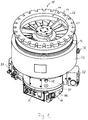
- Vacuum pump 10 shown comprises a housing 16 with a pump inlet 14 surrounded by an inlet flange 12, in the housing 16 a plurality of pumping stages for conveying the pending at the pump inlet 14 gas to a provided at the lower part 90 of the housing pump outlet 74. Between the lower part 90 and the housing 16 is a Seal 81 arranged.
- the vacuum pump 10 comprises in the housing 16 or in the lower part 90 a stator and a rotor with a rotor shaft 20 rotatably mounted about a rotation axis 18.
- the vacuum pump 10 is designed as a turbomolecular pump and comprises a plurality of pump-effectively connected in series with each other in turbomolecular pumping stages with a plurality of turbomolecular rotor disks 22 connected to the rotor shaft 20 and a plurality of turbomolecular stator disks 24 arranged in the axial direction between the rotor disks 22 and fixed in the housing 16, which are held at a desired axial distance from one another by spacer rings 26.
- the pump-active system realized by means of the turbomolecular pumping stages therefore builds up in regular alternation of rotor disks 22 and stator disks 24. Only a few of the components shown were marked with numbers for readability.
- the rotor disks 22 and stator disks 24 provide in a scooping region 28 an axial pumping action directed in the direction of the arrow 30.
- the vacuum pump 10 may optionally have subordinate to the turbomolecular pumping stages one or more, known per se Holweck pumping stages, which are not shown.
- three Holweck pumping stages which are arranged one inside the other in the radial direction and pump-connected with one another in series, may be provided.
- the rotor-side part of the Holweck pumping stages may have a rotor hub connected to the rotor shaft 20 and two cylinder shell-shaped Holweck rotor sleeves fastened to the rotor hub and supported by the latter, which are oriented coaxially to the rotor axis 18 and are nested one inside the other in the radial direction.
- Holweck stator sleeves can be provided, which are also oriented coaxially with the axis of rotation 18 and are nested in the radial direction.
- the pump-active surfaces of the Holweck pump stages are each formed by the radial lateral surfaces of a Holweck rotor sleeve and a Holweck stator sleeve opposite one another, forming a narrow radial Holweck gap.
- one of the pump-active surfaces is smooth, in particular that of the Holweck rotor sleeve, and the opposite pump-active surface, in particular the Holweck stator, has a structuring with helically around the rotation axis 18 in the axial direction extending grooves in which through the Rotation of the rotor the gas is propelled and thereby pumped.
- the Holweck pump stages are not provided.
- a sealing region 34 is formed by a specially, in this case asymmetrically shaped, stator disk 24 which minimizes the remaining gaps to the rotor disks 22 to provide better sealing against unwanted backflow between the first and second pumping stages.
- a biasing and sealing ring 32 is disposed between the inner wall of the housing 16 and the turbomolecular pumping stages, in particular between two spacer rings 26.
- the biasing and sealing ring 32 ensures that the tolerance-laden stack of spacer rings 26 is securely biased axially between the housing 16 and lower part 90. Furthermore, it additionally seals the gap between the stack of spacer rings 26 and the wall of the housing 16 against unwanted backflow from the pre-vacuum / ejection area into the high-vacuum / suction area.
- a flood gas inlet 36 is arranged, via which the vacuum pump 10 can be flooded with flooding gas.
- the tide gas inlet 36 is advantageously pump downstream or below the biasing and sealing ring 32.
- the lying at the height of the connection spacer ring 26 is preferably provided on its lateral surface over the entire circumference with a channel or a recess, so that the tidal gas first throughout Distributed annular channel with good conductance and then as uniformly as possible penetrates the gap or the recesses in the stator stack with a lower conductance over the circumference and reaches the mechanically more stable upstream prevacuum pump stages against flooding.
- a coolant inlet 38 and a coolant outlet 40 are arranged, between which runs a coolant line formed by at least one coolant tube 76.
- the coolant line runs in turns by a axially disposed cooling plate 89 disposed between the base 90 and a control unit, and a radially disposed cooling plate 71 disposed between the base 90 and a lubricant pump 78, the respective portions of the coolant line in the cooling plates 71 and 89 via a coolant connection line 39 are connected.
- a coolant pump can be connected, by means of which cooling liquid can be pumped through the coolant line in order to cool the vacuum pump 10.
- the pipe ends of the coolant pipe 76 may protrude out of the contour of the pump 10 at any angle, as a respective pipe section, at any angle, e.g. to be connected with insulation displacement fittings or special connectors at the inlet 38 or outlet 40.
- a sealed connection of tube 76 and inlet 38 or outlet 40 can be made in various ways, e.g. by soldering, welding, clamping / pressing / stretching or with separate sealing elements, for example, in particular cutting, sealing rings or bands or with special connectors with integrated sealing system.
- the rotatable mounting of the rotor shaft 20 is effected by a rolling bearing 42 in the region of the pump outlet 74 and a permanent magnet bearing 44 in the region of the pump inlet 14.
- the permanent magnet bearing 44 comprises a rotor-side bearing half 46 and a stator bearing half 48, each comprising a ring stack of a plurality of stacked in the axial direction of permanent magnetic rings 50, 52, wherein the magnetic rings 50, 52 facing each other with formation of a radial bearing gap 54.
- an emergency or fishing camp 56 is provided, which is designed as an unlubricated roller bearing and stands still during normal operation of the vacuum pump without contact and only with an excessive radial deflection of the rotor relative to the stator engages and rotation to a radial Form stop for the rotor, which prevents a collision of the rotor-side structures with the stator-side structures.
- the emergency or safety bearing 56 is taken separately via an insert and can therefore be changed independently of the permanent magnet bearing 44.
- the rolling bearing 42 is gripped by a ring holder, which in turn is axially and radially decoupled by elastomeric elements in a rolling bearing support or rolling bearing mount 84 is received, which is securely fixed to the lower part 90.
- Mechanical stops limit the possible relative movements between the ring holder and the roller bearing suspension 84.
- a conical spray screw 58 with an outer diameter which increases towards the rolling bearing 42 is provided on the rotor shaft 20, which can receive operating means, in particular lubricants, supplied by means of a lubricant channel 60 and feed it to the rolling bearing.
- the propeller screw 58 may preferably according to EP 2 740 956 A2 be designed.
- the resource is circulated by the lubricant pump 78.
- the lubricant pump 78 is preferably according to EP 2 060 794 A2 built up. In particular, it can supply a lubricant supply channel which, at least in a segment according to EP 2 801 725 A2 constructed as an O-ring sealed round channel.
- the vacuum pump 10 includes a drive motor 62 for rotatably driving the rotor whose rotor is formed by the rotor shaft 20.
- the control unit 64 controls the drive motor 62. Via an electrical connection 66, the vacuum pump 10 and in particular the control unit 64 and the drive motor 62 can be supplied with electric current.
- the control unit 64 forms the lower portion of the housing and is closed by the lid 80.
- one or more seals 77 may be inserted peripherally between control unit 64, cover 80, cooling plate 89 and / or lower part 90 or with other sealing means, such as liquid sealants, adhesives or in particular applicable mold seals the corresponding transitions are closed in order to obtain security against the ingress of media and / or impurities.
- the current can be conducted through the cover 80 into the housing 16 or the lower part 90 and, in particular, fed to the drive motor 62.
- the vacuum feedthrough 86 can according to EP 1 843 043 A2 be configured, in the example described here, a board with multiple sealing rings separately different voltage potentials and signals from each other separately from the pump interior, ie from the vacuum area, outwards, so the "atmosphere" and in particular to the control unit 64 leads.
- both the control unit 64 or on the part of the drive motor 62 or on the part of the pump-active components on the housing 16 mainly undesirable heat into the pump can be introduced.
- the coolant such as water, advantageously flows from the inlet 38 to the outlet 40 when, for example, the lubricant pump 78 is to be kept coolest.
- the coolant may also be from outlet 40, which is then the inlet forms, to the inlet 38, which then forms the outlet, flow, for example, when the control unit 64 requires more cooling.
- a heater 73 designed as a heating device is provided for a pump-effective section, which is formed here by the rotor and stator disks 22 and 24, a heater 73 designed as a heating device is provided. By means of this, for example, condensation of process gas in the pump can be avoided.
- a heating control unit 87 is provided, which is attached here laterally to the pump 10.
- the heater control unit 87 is advantageously mounted on a cooling plate 89 to allow for the best possible cooling of electrical or electronic power assemblies included in the heater control unit 87. Depending on the design, this connection can be made directly or by thermally conductive adapter elements.
- an insulating cross-section 75 is provided in the lower part 90, which is formed by a puncture in the lower part 90. This causes due to its small cross-sectional area a reduced heat transfer, thus forming an insulation.
- a covering 88 in particular for covering the insulation cross section 75, can be arranged on the radial outer side of the lower part 90.
- the cladding 88 may, for example, be designed in the form of a jacket as a sheet metal sleeve slotted along the axis of rotation 18 of the pump 10.
- the cover 88 may have one or more viewing windows or cut-outs to perform any connections of the lower part 90, such as a sealing gas inlet 68 to the outside or to share the view of the type data, such as nameplate or engraving, the pump 10, which in particular unsolvable on Lower part 90 are attached.
- a barrier gas inlet 68 which is in Fig. 1 is sealed with a hexagon stopper for a use without sealing gas supply.
- the barrier gas inlet 68 is also referred to as flushing gas connection.
- Purge gas may be introduced via the purge gas inlet 68 to protect the engine 62 in the engine compartment in which the engine 62 is housed.
- the gas introduced via the blocking gas inlet 68 in the region of the engine protects the components located in the lower part 90 from corrosive and / or self-depositing media, which can occur in the pumping system depending on the application.
- a seal 83 is arranged, so that a labyrinth seal 72 as the only remaining passage on the one hand with their low conductance is a barrier against incoming media in the engine and roller bearing area and continue to increase saturation of Wälzlager- and engine area with Locking / inert gas ensures.
- the labyrinth seal 72 is provided between an engine compartment 82 which delimits the engine compartment at the top and the lower rotor disk 22.
- the electric drive motor 62 is advantageously protected by a potting compound against corrosion.
- the motor support 82 is integrally molded integrally with the drive motor, so that the entire unit including the integrally formed with the motor mount stator side of the labyrinth seal 72 can be optimally aligned or centered in one step with the lower part 90.
- the fore-vacuum region Radially outside the labyrinth seal 72 and below the turbomolecular pumping stages is the fore-vacuum region, in which, in particular, a chamber 70, which runs around the rotational axis 18 in a ring-shaped fashion, which, as in FIG Fig. 3 can be seen, has a substantially rectangular cross section.
- this cross-sectional shape is only to be regarded as an example, so that a different cross-sectional shape, for example a square or circular cross-section, can also be realized.
- the chamber 70 may also be at another Place in the housing 16 and housed in the lower part 90.
- the chamber 70 is where most of the deposits occur, typically in the fore-vacuum region.
- the chamber 70 is thus located between the last pumping stage and the pump outlet 74.
- the chamber 70 opens into the pump outlet 74.
- the chamber 70 therefore forms an ejection area for the gas pumped by the vacuum pump 10 from the inlet 14, which can pass via the pump outlet 74 into a backing pump (not shown) connected thereto.
- the fore-vacuum pump can then further convey the gas, for example into a line for exhaust gas which is under normal pressure.
- the above-described vacuum pump 10 of Fig. 1 to 3 has no inventively arranged insulation. However, it can advantageously be developed further according to the invention, for example as shown schematically in FIG Fig. 4 and 5 is indicated. Conversely, in the Fig. 4 and 5 shown embodiments of the invention advantageously by one or more features of the vacuum pump Fig. 1 to 3 further training.
- a vacuum pump 10 designed as a turbomolecular pump which comprises a first housing component 92 and a second housing component 94.
- the first housing component 92 comprises a pump-effective section of the vacuum pump 10, while the second housing component 94 comprises a control for the vacuum pump 10.
- the first housing component 92 may, for example, a housing 16 and / or a lower part 90 according to the embodiment of Fig. 1 to 3 include.
- a heating device designed as a heating sleeve 73 is provided on the first housing part 92.
- a heating control unit 87 is provided, which is laterally attached to the vacuum pump 10, here on the cooling plate 89
- the cooling device designed as a cooling plate 89 for the control in the second housing member 94 is disposed between the second housing member 94 and the first housing member 92, and extends with respect to a rotor axis over an entire radial gap between the second and the first housing member 94 and 92nd
- an insulating device which comprises an air gap 98, which is formed by spacers 96.
- the spacers 96 are formed as washers for screws, not shown, which secure the second housing member 94 to the first housing member 92.
- a sealing ring 100 for example, an O-ring, is also provided, which can protect an inner of the first housing member 92 and / or the second housing member 94, for example against ingress of water and / or particles, in particular according to IP54.
- the first housing member 92, the air gap 98, the cooling plate 89 and the second housing member 94 are arranged in the axial direction, which is defined by a rotor axis, successively.
- the size of the spacers is selected so that the sealing ring 100 between the cooling plate 89 and the first housing member 92, the seal, in particular a board, reliably effected.
- the construction for the sealing ring 100 corresponds in particular to that of a known vacuum pump. The invention can therefore be easily integrated into an existing pump design.
- Vacuum pump 10 shown also includes a first housing portion 92 for a pumping effective portion, an air gap formed as an insulating device 98, a cooling plate 89 and a second housing member 94 for a controller. Also, a heating sleeve 73 is provided with an associated heater control unit 87.
- the air gap 98 is in the embodiment of the Fig. 5 however, formed by a plurality of spacers formed as projections 102. These are formed circumferentially in the embodiment shown around the rotor axis, but may for example also be interrupted and / or only selectively provided.
- a sealing ring 100 is enclosed here in each case by such a projection 102 on the inside and outside. Alternatively, the projections there may also be shorter than the remaining projections 102 in order to improve the seal by the sealing ring 100. Alternatively or additionally, similar projections may for example also be provided on the cooling plate 89.
Landscapes
- Engineering & Computer Science (AREA)
- Mechanical Engineering (AREA)
- General Engineering & Computer Science (AREA)
- Physics & Mathematics (AREA)
- Thermal Sciences (AREA)
- Non-Positive Displacement Air Blowers (AREA)
Priority Applications (1)
| Application Number | Priority Date | Filing Date | Title |
|---|---|---|---|
| EP17193821.0A EP3462034B1 (fr) | 2017-09-28 | 2017-09-28 | Pompe à vide |
Applications Claiming Priority (1)
| Application Number | Priority Date | Filing Date | Title |
|---|---|---|---|
| EP17193821.0A EP3462034B1 (fr) | 2017-09-28 | 2017-09-28 | Pompe à vide |
Publications (2)
| Publication Number | Publication Date |
|---|---|
| EP3462034A1 true EP3462034A1 (fr) | 2019-04-03 |
| EP3462034B1 EP3462034B1 (fr) | 2024-09-11 |
Family
ID=59997178
Family Applications (1)
| Application Number | Title | Priority Date | Filing Date |
|---|---|---|---|
| EP17193821.0A Active EP3462034B1 (fr) | 2017-09-28 | 2017-09-28 | Pompe à vide |
Country Status (1)
| Country | Link |
|---|---|
| EP (1) | EP3462034B1 (fr) |
Cited By (3)
| Publication number | Priority date | Publication date | Assignee | Title |
|---|---|---|---|---|
| CN112727787A (zh) * | 2019-10-28 | 2021-04-30 | 株式会社岛津制作所 | 真空泵 |
| CN116018464A (zh) * | 2020-09-10 | 2023-04-25 | 埃地沃兹日本有限公司 | 真空泵 |
| CN117043469A (zh) * | 2021-04-15 | 2023-11-10 | 埃地沃兹日本有限公司 | 涡轮分子泵 |
Citations (8)
| Publication number | Priority date | Publication date | Assignee | Title |
|---|---|---|---|---|
| EP1843043A2 (fr) | 2006-04-07 | 2007-10-10 | Pfeiffer Vacuum Gmbh | Pompe à vide avec un appareil d'entraînement |
| WO2008062598A1 (fr) * | 2006-11-22 | 2008-05-29 | Edwards Japan Limited | Pompe à vide |
| EP2060794A2 (fr) | 2007-11-13 | 2009-05-20 | Pfeiffer Vacuum GmbH | Pompe à vide dotée d'une pompe à lubrifiant |
| WO2012046495A1 (fr) * | 2010-10-07 | 2012-04-12 | エドワーズ株式会社 | Dispositif de commande de pompe à vide et pompe à vide |
| JP2013100760A (ja) * | 2011-11-08 | 2013-05-23 | Shimadzu Corp | 一体型ターボ分子ポンプ |
| EP2740956A2 (fr) | 2012-12-05 | 2014-06-11 | Pfeiffer Vacuum GmbH | Dispositif de lubrification pour un palier à roulement |
| EP2801725A2 (fr) | 2013-05-10 | 2014-11-12 | Pfeiffer Vacuum Gmbh | Dispositif comprenant au moins un canal pour l'acheminement d'un fluide de travail gazeux ou liquide |
| US20150086328A1 (en) * | 2013-09-24 | 2015-03-26 | Shimadzu Corporation | Turbo-molecular pump |
-
2017
- 2017-09-28 EP EP17193821.0A patent/EP3462034B1/fr active Active
Patent Citations (8)
| Publication number | Priority date | Publication date | Assignee | Title |
|---|---|---|---|---|
| EP1843043A2 (fr) | 2006-04-07 | 2007-10-10 | Pfeiffer Vacuum Gmbh | Pompe à vide avec un appareil d'entraînement |
| WO2008062598A1 (fr) * | 2006-11-22 | 2008-05-29 | Edwards Japan Limited | Pompe à vide |
| EP2060794A2 (fr) | 2007-11-13 | 2009-05-20 | Pfeiffer Vacuum GmbH | Pompe à vide dotée d'une pompe à lubrifiant |
| WO2012046495A1 (fr) * | 2010-10-07 | 2012-04-12 | エドワーズ株式会社 | Dispositif de commande de pompe à vide et pompe à vide |
| JP2013100760A (ja) * | 2011-11-08 | 2013-05-23 | Shimadzu Corp | 一体型ターボ分子ポンプ |
| EP2740956A2 (fr) | 2012-12-05 | 2014-06-11 | Pfeiffer Vacuum GmbH | Dispositif de lubrification pour un palier à roulement |
| EP2801725A2 (fr) | 2013-05-10 | 2014-11-12 | Pfeiffer Vacuum Gmbh | Dispositif comprenant au moins un canal pour l'acheminement d'un fluide de travail gazeux ou liquide |
| US20150086328A1 (en) * | 2013-09-24 | 2015-03-26 | Shimadzu Corporation | Turbo-molecular pump |
Cited By (8)
| Publication number | Priority date | Publication date | Assignee | Title |
|---|---|---|---|---|
| CN112727787A (zh) * | 2019-10-28 | 2021-04-30 | 株式会社岛津制作所 | 真空泵 |
| CN112727787B (zh) * | 2019-10-28 | 2022-07-12 | 株式会社岛津制作所 | 真空泵 |
| US11566626B2 (en) | 2019-10-28 | 2023-01-31 | Shimadzu Corporation | Vacuum pump |
| CN116018464A (zh) * | 2020-09-10 | 2023-04-25 | 埃地沃兹日本有限公司 | 真空泵 |
| EP4212729A4 (fr) * | 2020-09-10 | 2024-08-14 | Edwards Japan Limited | Pompe à vide |
| CN117043469A (zh) * | 2021-04-15 | 2023-11-10 | 埃地沃兹日本有限公司 | 涡轮分子泵 |
| US20240254980A1 (en) * | 2021-04-15 | 2024-08-01 | Edwards Japan Limited | Turbomolecular pump |
| US12571382B2 (en) * | 2021-04-15 | 2026-03-10 | Edwards Japan Limited | Turbomolecular pump |
Also Published As
| Publication number | Publication date |
|---|---|
| EP3462034B1 (fr) | 2024-09-11 |
Similar Documents
| Publication | Publication Date | Title |
|---|---|---|
| DE19702456B4 (de) | Vakuumpumpe | |
| EP3347598B1 (fr) | Ventilateur turbo avec élément de refroidissement | |
| EP2807732B1 (fr) | Machine électrique et rotor pour refroidir la machine électrique | |
| EP2390510B1 (fr) | Pompe à vide | |
| DE102017120039B4 (de) | Kühlmittelpumpe mit anwendungsoptimiertem Aufbau | |
| DE10047387A1 (de) | Elektrisch angetriebene Kühlmittelpumpe | |
| EP3462034B1 (fr) | Pompe à vide | |
| DE112006000639B4 (de) | Turbolader mit elektrischer Rotationsmaschine einer Brennkraftmaschine | |
| DE102020214275A1 (de) | Elektrisch angetriebene Luftzuführvorrichtung | |
| DE4229395A1 (de) | Oberflächengekühlte, geschlossene elektrische Maschine | |
| EP3759356B1 (fr) | Pompe électrique à réfrigérant | |
| EP4108932A1 (fr) | Reciate et pompe à vide élevé | |
| DE102017109253B4 (de) | Kühlmittelpumpe mit druckausgleichender Medientrennung | |
| EP1866546B1 (fr) | Pompe a rotor noye | |
| EP3318763B1 (fr) | Étanchéité au vide, étanchéité double, système à vide et pompe à vide | |
| EP3431769B1 (fr) | Pompe à vide | |
| EP2738915A2 (fr) | Refroidissement d'un compartiment de tête de bobine | |
| EP3327293B1 (fr) | Pompe à vide avec une pluralté d'entrées | |
| DE102021126074B4 (de) | Elektrische Maschine mit Rotorkühlung | |
| EP4212730A1 (fr) | Pompe à vide avec étage de pompage de holward optimisé pour compenser la perte de performance liée à la température | |
| EP3339652B1 (fr) | Pompe à vide avec chemise intérieure recueillant des dépôts | |
| DE102018129611A1 (de) | Rotormontageeinheit mit Kühlfunktion | |
| EP1288502A2 (fr) | Pompe à vide turbo-moléculaire | |
| WO2023131409A1 (fr) | Pompe à liquide de refroidissement pour le circuit de refroidissement d'un véhicule | |
| EP3760872A1 (fr) | Pompe à vide pourvue d'un agencement de fixation destiné à l'application de la pompe à une structure de fixation ainsi qu'un poste de pompage doté d'une telle pompe à vide montée sur celui-ci |
Legal Events
| Date | Code | Title | Description |
|---|---|---|---|
| PUAI | Public reference made under article 153(3) epc to a published international application that has entered the european phase |
Free format text: ORIGINAL CODE: 0009012 |
|
| STAA | Information on the status of an ep patent application or granted ep patent |
Free format text: STATUS: THE APPLICATION HAS BEEN PUBLISHED |
|
| AK | Designated contracting states |
Kind code of ref document: A1 Designated state(s): AL AT BE BG CH CY CZ DE DK EE ES FI FR GB GR HR HU IE IS IT LI LT LU LV MC MK MT NL NO PL PT RO RS SE SI SK SM TR |
|
| AX | Request for extension of the european patent |
Extension state: BA ME |
|
| STAA | Information on the status of an ep patent application or granted ep patent |
Free format text: STATUS: REQUEST FOR EXAMINATION WAS MADE |
|
| 17P | Request for examination filed |
Effective date: 20190905 |
|
| RBV | Designated contracting states (corrected) |
Designated state(s): AL AT BE BG CH CY CZ DE DK EE ES FI FR GB GR HR HU IE IS IT LI LT LU LV MC MK MT NL NO PL PT RO RS SE SI SK SM TR |
|
| STAA | Information on the status of an ep patent application or granted ep patent |
Free format text: STATUS: EXAMINATION IS IN PROGRESS |
|
| 17Q | First examination report despatched |
Effective date: 20211105 |
|
| GRAP | Despatch of communication of intention to grant a patent |
Free format text: ORIGINAL CODE: EPIDOSNIGR1 |
|
| STAA | Information on the status of an ep patent application or granted ep patent |
Free format text: STATUS: GRANT OF PATENT IS INTENDED |
|
| GRAS | Grant fee paid |
Free format text: ORIGINAL CODE: EPIDOSNIGR3 |
|
| GRAA | (expected) grant |
Free format text: ORIGINAL CODE: 0009210 |
|
| STAA | Information on the status of an ep patent application or granted ep patent |
Free format text: STATUS: THE PATENT HAS BEEN GRANTED |
|
| INTG | Intention to grant announced |
Effective date: 20240715 |
|
| AK | Designated contracting states |
Kind code of ref document: B1 Designated state(s): AL AT BE BG CH CY CZ DE DK EE ES FI FR GB GR HR HU IE IS IT LI LT LU LV MC MK MT NL NO PL PT RO RS SE SI SK SM TR |
|
| REG | Reference to a national code |
Ref country code: GB Ref legal event code: FG4D Free format text: NOT ENGLISH |
|
| REG | Reference to a national code |
Ref country code: CH Ref legal event code: EP |
|
| REG | Reference to a national code |
Ref country code: DE Ref legal event code: R096 Ref document number: 502017016421 Country of ref document: DE |
|
| REG | Reference to a national code |
Ref country code: IE Ref legal event code: FG4D Free format text: LANGUAGE OF EP DOCUMENT: GERMAN |
|
| REG | Reference to a national code |
Ref country code: LT Ref legal event code: MG9D |
|
| PG25 | Lapsed in a contracting state [announced via postgrant information from national office to epo] |
Ref country code: NO Free format text: LAPSE BECAUSE OF FAILURE TO SUBMIT A TRANSLATION OF THE DESCRIPTION OR TO PAY THE FEE WITHIN THE PRESCRIBED TIME-LIMIT Effective date: 20241211 |
|
| REG | Reference to a national code |
Ref country code: NL Ref legal event code: MP Effective date: 20240911 |
|
| PG25 | Lapsed in a contracting state [announced via postgrant information from national office to epo] |
Ref country code: GR Free format text: LAPSE BECAUSE OF FAILURE TO SUBMIT A TRANSLATION OF THE DESCRIPTION OR TO PAY THE FEE WITHIN THE PRESCRIBED TIME-LIMIT Effective date: 20241212 Ref country code: FI Free format text: LAPSE BECAUSE OF FAILURE TO SUBMIT A TRANSLATION OF THE DESCRIPTION OR TO PAY THE FEE WITHIN THE PRESCRIBED TIME-LIMIT Effective date: 20240911 |
|
| PG25 | Lapsed in a contracting state [announced via postgrant information from national office to epo] |
Ref country code: BG Free format text: LAPSE BECAUSE OF FAILURE TO SUBMIT A TRANSLATION OF THE DESCRIPTION OR TO PAY THE FEE WITHIN THE PRESCRIBED TIME-LIMIT Effective date: 20240911 |
|
| PG25 | Lapsed in a contracting state [announced via postgrant information from national office to epo] |
Ref country code: LV Free format text: LAPSE BECAUSE OF FAILURE TO SUBMIT A TRANSLATION OF THE DESCRIPTION OR TO PAY THE FEE WITHIN THE PRESCRIBED TIME-LIMIT Effective date: 20240911 |
|
| PG25 | Lapsed in a contracting state [announced via postgrant information from national office to epo] |
Ref country code: HR Free format text: LAPSE BECAUSE OF FAILURE TO SUBMIT A TRANSLATION OF THE DESCRIPTION OR TO PAY THE FEE WITHIN THE PRESCRIBED TIME-LIMIT Effective date: 20240911 |
|
| PG25 | Lapsed in a contracting state [announced via postgrant information from national office to epo] |
Ref country code: ES Free format text: LAPSE BECAUSE OF FAILURE TO SUBMIT A TRANSLATION OF THE DESCRIPTION OR TO PAY THE FEE WITHIN THE PRESCRIBED TIME-LIMIT Effective date: 20240911 Ref country code: RS Free format text: LAPSE BECAUSE OF FAILURE TO SUBMIT A TRANSLATION OF THE DESCRIPTION OR TO PAY THE FEE WITHIN THE PRESCRIBED TIME-LIMIT Effective date: 20241211 |
|
| PG25 | Lapsed in a contracting state [announced via postgrant information from national office to epo] |
Ref country code: RS Free format text: LAPSE BECAUSE OF FAILURE TO SUBMIT A TRANSLATION OF THE DESCRIPTION OR TO PAY THE FEE WITHIN THE PRESCRIBED TIME-LIMIT Effective date: 20241211 Ref country code: NO Free format text: LAPSE BECAUSE OF FAILURE TO SUBMIT A TRANSLATION OF THE DESCRIPTION OR TO PAY THE FEE WITHIN THE PRESCRIBED TIME-LIMIT Effective date: 20241211 Ref country code: LV Free format text: LAPSE BECAUSE OF FAILURE TO SUBMIT A TRANSLATION OF THE DESCRIPTION OR TO PAY THE FEE WITHIN THE PRESCRIBED TIME-LIMIT Effective date: 20240911 Ref country code: HR Free format text: LAPSE BECAUSE OF FAILURE TO SUBMIT A TRANSLATION OF THE DESCRIPTION OR TO PAY THE FEE WITHIN THE PRESCRIBED TIME-LIMIT Effective date: 20240911 Ref country code: GR Free format text: LAPSE BECAUSE OF FAILURE TO SUBMIT A TRANSLATION OF THE DESCRIPTION OR TO PAY THE FEE WITHIN THE PRESCRIBED TIME-LIMIT Effective date: 20241212 Ref country code: FI Free format text: LAPSE BECAUSE OF FAILURE TO SUBMIT A TRANSLATION OF THE DESCRIPTION OR TO PAY THE FEE WITHIN THE PRESCRIBED TIME-LIMIT Effective date: 20240911 Ref country code: ES Free format text: LAPSE BECAUSE OF FAILURE TO SUBMIT A TRANSLATION OF THE DESCRIPTION OR TO PAY THE FEE WITHIN THE PRESCRIBED TIME-LIMIT Effective date: 20240911 Ref country code: BG Free format text: LAPSE BECAUSE OF FAILURE TO SUBMIT A TRANSLATION OF THE DESCRIPTION OR TO PAY THE FEE WITHIN THE PRESCRIBED TIME-LIMIT Effective date: 20240911 |
|
| PG25 | Lapsed in a contracting state [announced via postgrant information from national office to epo] |
Ref country code: NL Free format text: LAPSE BECAUSE OF FAILURE TO SUBMIT A TRANSLATION OF THE DESCRIPTION OR TO PAY THE FEE WITHIN THE PRESCRIBED TIME-LIMIT Effective date: 20240911 |
|
| PG25 | Lapsed in a contracting state [announced via postgrant information from national office to epo] |
Ref country code: PT Free format text: LAPSE BECAUSE OF FAILURE TO SUBMIT A TRANSLATION OF THE DESCRIPTION OR TO PAY THE FEE WITHIN THE PRESCRIBED TIME-LIMIT Effective date: 20250113 Ref country code: IS Free format text: LAPSE BECAUSE OF FAILURE TO SUBMIT A TRANSLATION OF THE DESCRIPTION OR TO PAY THE FEE WITHIN THE PRESCRIBED TIME-LIMIT Effective date: 20250111 |
|
| PG25 | Lapsed in a contracting state [announced via postgrant information from national office to epo] |
Ref country code: SM Free format text: LAPSE BECAUSE OF FAILURE TO SUBMIT A TRANSLATION OF THE DESCRIPTION OR TO PAY THE FEE WITHIN THE PRESCRIBED TIME-LIMIT Effective date: 20240911 Ref country code: RO Free format text: LAPSE BECAUSE OF FAILURE TO SUBMIT A TRANSLATION OF THE DESCRIPTION OR TO PAY THE FEE WITHIN THE PRESCRIBED TIME-LIMIT Effective date: 20240911 |
|
| PG25 | Lapsed in a contracting state [announced via postgrant information from national office to epo] |
Ref country code: EE Free format text: LAPSE BECAUSE OF FAILURE TO SUBMIT A TRANSLATION OF THE DESCRIPTION OR TO PAY THE FEE WITHIN THE PRESCRIBED TIME-LIMIT Effective date: 20240911 |
|
| PG25 | Lapsed in a contracting state [announced via postgrant information from national office to epo] |
Ref country code: PL Free format text: LAPSE BECAUSE OF FAILURE TO SUBMIT A TRANSLATION OF THE DESCRIPTION OR TO PAY THE FEE WITHIN THE PRESCRIBED TIME-LIMIT Effective date: 20240911 |
|
| PG25 | Lapsed in a contracting state [announced via postgrant information from national office to epo] |
Ref country code: SK Free format text: LAPSE BECAUSE OF FAILURE TO SUBMIT A TRANSLATION OF THE DESCRIPTION OR TO PAY THE FEE WITHIN THE PRESCRIBED TIME-LIMIT Effective date: 20240911 |
|
| REG | Reference to a national code |
Ref country code: CH Ref legal event code: PL |
|
| PG25 | Lapsed in a contracting state [announced via postgrant information from national office to epo] |
Ref country code: LU Free format text: LAPSE BECAUSE OF NON-PAYMENT OF DUE FEES Effective date: 20240928 |
|
| REG | Reference to a national code |
Ref country code: DE Ref legal event code: R097 Ref document number: 502017016421 Country of ref document: DE |
|
| PG25 | Lapsed in a contracting state [announced via postgrant information from national office to epo] |
Ref country code: MC Free format text: LAPSE BECAUSE OF FAILURE TO SUBMIT A TRANSLATION OF THE DESCRIPTION OR TO PAY THE FEE WITHIN THE PRESCRIBED TIME-LIMIT Effective date: 20240911 |
|
| PG25 | Lapsed in a contracting state [announced via postgrant information from national office to epo] |
Ref country code: DK Free format text: LAPSE BECAUSE OF FAILURE TO SUBMIT A TRANSLATION OF THE DESCRIPTION OR TO PAY THE FEE WITHIN THE PRESCRIBED TIME-LIMIT Effective date: 20240911 |
|
| REG | Reference to a national code |
Ref country code: BE Ref legal event code: MM Effective date: 20240930 |
|
| PG25 | Lapsed in a contracting state [announced via postgrant information from national office to epo] |
Ref country code: BE Free format text: LAPSE BECAUSE OF NON-PAYMENT OF DUE FEES Effective date: 20240930 |
|
| PLBE | No opposition filed within time limit |
Free format text: ORIGINAL CODE: 0009261 |
|
| STAA | Information on the status of an ep patent application or granted ep patent |
Free format text: STATUS: NO OPPOSITION FILED WITHIN TIME LIMIT |
|
| PG25 | Lapsed in a contracting state [announced via postgrant information from national office to epo] |
Ref country code: CH Free format text: LAPSE BECAUSE OF NON-PAYMENT OF DUE FEES Effective date: 20240930 |
|
| PG25 | Lapsed in a contracting state [announced via postgrant information from national office to epo] |
Ref country code: IE Free format text: LAPSE BECAUSE OF NON-PAYMENT OF DUE FEES Effective date: 20240928 |
|
| 26N | No opposition filed |
Effective date: 20250612 |
|
| PG25 | Lapsed in a contracting state [announced via postgrant information from national office to epo] |
Ref country code: SE Free format text: LAPSE BECAUSE OF FAILURE TO SUBMIT A TRANSLATION OF THE DESCRIPTION OR TO PAY THE FEE WITHIN THE PRESCRIBED TIME-LIMIT Effective date: 20240911 |
|
| PGFP | Annual fee paid to national office [announced via postgrant information from national office to epo] |
Ref country code: IT Payment date: 20250923 Year of fee payment: 9 |
|
| PGFP | Annual fee paid to national office [announced via postgrant information from national office to epo] |
Ref country code: GB Payment date: 20250919 Year of fee payment: 9 |
|
| PG25 | Lapsed in a contracting state [announced via postgrant information from national office to epo] |
Ref country code: FR Free format text: LAPSE BECAUSE OF NON-PAYMENT OF DUE FEES Effective date: 20241111 |
|
| PGFP | Annual fee paid to national office [announced via postgrant information from national office to epo] |
Ref country code: CZ Payment date: 20250925 Year of fee payment: 9 |
|
| REG | Reference to a national code |
Ref country code: AT Ref legal event code: MM01 Ref document number: 1722903 Country of ref document: AT Kind code of ref document: T Effective date: 20240928 |
|
| PGFP | Annual fee paid to national office [announced via postgrant information from national office to epo] |
Ref country code: DE Payment date: 20251126 Year of fee payment: 9 |
|
| PG25 | Lapsed in a contracting state [announced via postgrant information from national office to epo] |
Ref country code: AT Free format text: LAPSE BECAUSE OF NON-PAYMENT OF DUE FEES Effective date: 20240928 |
|
| PG25 | Lapsed in a contracting state [announced via postgrant information from national office to epo] |
Ref country code: CY Free format text: LAPSE BECAUSE OF FAILURE TO SUBMIT A TRANSLATION OF THE DESCRIPTION OR TO PAY THE FEE WITHIN THE PRESCRIBED TIME-LIMIT; INVALID AB INITIO Effective date: 20170928 |
|
| PG25 | Lapsed in a contracting state [announced via postgrant information from national office to epo] |
Ref country code: HU Free format text: LAPSE BECAUSE OF FAILURE TO SUBMIT A TRANSLATION OF THE DESCRIPTION OR TO PAY THE FEE WITHIN THE PRESCRIBED TIME-LIMIT; INVALID AB INITIO Effective date: 20170928 |